EP2762638B1 - Dispositif de tamisage modulaire et utilisation d'un dispositif de tamisage modulaire pour nettoyer le ballast d'une voie ferrée - Google Patents
Dispositif de tamisage modulaire et utilisation d'un dispositif de tamisage modulaire pour nettoyer le ballast d'une voie ferrée Download PDFInfo
- Publication number
- EP2762638B1 EP2762638B1 EP14151842.3A EP14151842A EP2762638B1 EP 2762638 B1 EP2762638 B1 EP 2762638B1 EP 14151842 A EP14151842 A EP 14151842A EP 2762638 B1 EP2762638 B1 EP 2762638B1
- Authority
- EP
- European Patent Office
- Prior art keywords
- module
- sieve
- vibration
- ballast
- frame
- Prior art date
- Legal status (The legal status is an assumption and is not a legal conclusion. Google has not performed a legal analysis and makes no representation as to the accuracy of the status listed.)
- Active
Links
- 238000004140 cleaning Methods 0.000 title claims description 28
- 238000007873 sieving Methods 0.000 title description 5
- 239000002245 particle Substances 0.000 claims description 23
- 229910000831 Steel Inorganic materials 0.000 claims description 22
- 239000010959 steel Substances 0.000 claims description 22
- 238000013016 damping Methods 0.000 claims description 13
- 229920001971 elastomer Polymers 0.000 claims description 13
- 239000000356 contaminant Substances 0.000 claims description 9
- 239000000806 elastomer Substances 0.000 claims description 9
- 239000004033 plastic Substances 0.000 claims description 6
- 239000004576 sand Substances 0.000 claims description 6
- 239000000919 ceramic Substances 0.000 claims description 3
- 238000010276 construction Methods 0.000 claims description 3
- 230000005484 gravity Effects 0.000 claims description 3
- 229910052500 inorganic mineral Inorganic materials 0.000 claims description 3
- 239000002184 metal Substances 0.000 claims description 3
- 239000002923 metal particle Substances 0.000 claims description 3
- 239000011707 mineral Substances 0.000 claims description 3
- 230000007704 transition Effects 0.000 claims description 3
- 239000000945 filler Substances 0.000 claims description 2
- 239000012798 spherical particle Substances 0.000 claims description 2
- 238000012216 screening Methods 0.000 description 21
- 239000012535 impurity Substances 0.000 description 8
- 238000013461 design Methods 0.000 description 4
- 239000000047 product Substances 0.000 description 4
- 230000002950 deficient Effects 0.000 description 3
- 239000004744 fabric Substances 0.000 description 3
- 238000012423 maintenance Methods 0.000 description 3
- 238000010924 continuous production Methods 0.000 description 2
- 230000008878 coupling Effects 0.000 description 2
- 238000010168 coupling process Methods 0.000 description 2
- 238000005859 coupling reaction Methods 0.000 description 2
- 238000007667 floating Methods 0.000 description 2
- 239000008187 granular material Substances 0.000 description 2
- 238000000034 method Methods 0.000 description 2
- 239000003973 paint Substances 0.000 description 2
- 239000000843 powder Substances 0.000 description 2
- 230000008569 process Effects 0.000 description 2
- 229910001111 Fine metal Inorganic materials 0.000 description 1
- 239000000654 additive Substances 0.000 description 1
- 230000000996 additive effect Effects 0.000 description 1
- 230000000712 assembly Effects 0.000 description 1
- 238000000429 assembly Methods 0.000 description 1
- 230000008859 change Effects 0.000 description 1
- 230000001419 dependent effect Effects 0.000 description 1
- 238000007599 discharging Methods 0.000 description 1
- 238000009826 distribution Methods 0.000 description 1
- 238000005265 energy consumption Methods 0.000 description 1
- 238000005516 engineering process Methods 0.000 description 1
- 230000003116 impacting effect Effects 0.000 description 1
- 238000004519 manufacturing process Methods 0.000 description 1
- 239000000463 material Substances 0.000 description 1
- 239000000203 mixture Substances 0.000 description 1
- 238000012544 monitoring process Methods 0.000 description 1
- 230000003287 optical effect Effects 0.000 description 1
- 238000012856 packing Methods 0.000 description 1
- 230000008439 repair process Effects 0.000 description 1
- 230000035939 shock Effects 0.000 description 1
- 239000013589 supplement Substances 0.000 description 1
- 238000005303 weighing Methods 0.000 description 1
Images

Classifications
-
- E—FIXED CONSTRUCTIONS
- E01—CONSTRUCTION OF ROADS, RAILWAYS, OR BRIDGES
- E01B—PERMANENT WAY; PERMANENT-WAY TOOLS; MACHINES FOR MAKING RAILWAYS OF ALL KINDS
- E01B27/00—Placing, renewing, working, cleaning, or taking-up the ballast, with or without concurrent work on the track; Devices therefor; Packing sleepers
- E01B27/06—Renewing or cleaning the ballast in situ, with or without concurrent work on the track
Definitions
- the present invention is arranged in the field of track ballast cleaning and relates to a modular screening device and the use of the modular screening device for cleaning track ballast that can be removed from a track bed.
- the present invention relates specifically to the area of track ballast cleaning.
- dirt has to be removed from coarse, angular gravel stones.
- the contaminants adhere to the coarse, angular track ballast and have to be removed by massive impacts:
- cleaning track ballast it is removed from the track bed in a small, limited area below the laid track, freed from adhesions and contaminants and returned to the track bed.
- the contaminants are usually loosened from the ballast by impact or shaking pulses, separated and ejected/disposed of outside the track bed.
- the cleaned track ballast - if necessary supplemented with additional fresh ballast - is returned to the track bed, while the cleaning is carried out slowly in a continuous process along a track section.
- Established devices for cleaning track ballast include: B. in the DE 29 45 767 C2 reveals: Bridge-like structures enclose a cleared track bed area a distance of several meters on both sides. Due to the support points being far away from the cleared area, the track sections floating freely without supporting track ballast will only interact insignificantly with the forces and impulses of the device.
- devices are also known in which the feet are extended laterally in order to provide a secure, clearly distant support point for the device. The disadvantage of the latter devices is that they can only be operated in sections and not in a continuous process, which means that the cleaning speed is significantly lower.
- the object of the present invention was therefore to overcome the disadvantages of the prior art and to provide an alternative to the established track ballast cleaning, which, despite its compact design and easier transport, is able to provide sufficient cleaning performance with comparable operating costs.
- an exclusive track ballast weighing up to 5 tons, modular screening device is designed for cleaning track ballast removed from below the screening device.
- a vibrating screen deck module sieves impurities from the gravel using gravity and is arranged in a frame module. The vibrations are taken into account in the design by dampening the vibrations of the screen deck using particulate vibration dampers and decoupling the frame and screen deck module from a vibration point of view.
- the inventors are interested in the use of particulate vibration dampers, such as those in DE 24 52 006 A1 described as an alternative to mechanical vibration dampers is unknown in the area of track bed cleaning.
- the inventors assume that vibration dampers will not be used because they will naturally initially dampen the vibration itself, i.e. one must assume that the vibrations of the screen deck itself will be hindered, which would prevent good cleaning performance.
- the inventors attribute this to the fact that, despite the long-standing need, no use or usable device with the claimed features is known or available on the market.
- the particulate vibration dampers used in the modular sieving device according to the invention have at least one type of particle selected from the group consisting of natural mineral particles, plastic particles, sand, metal particles, metal balls, ceramic balls, plastic balls, packings, ductile steel balls, superficially set - preferably thixotropically set - particles which are arranged in the transition from the screen deck module to the enclosing frame module, with the screen deck module and frame module being decoupled in terms of vibration technology by the particulate vibration dampers.
- the assemblies are decoupled surprisingly effectively: the vibrations of the screen deck are at best transmitted to the rest of the device in a damped manner with a significantly more diffuse, softer impulse. This trick made it possible for the first time to provide a light, compact screening device for cleaning track ballast, which offers the advantages of a compact design in combination with good cleaning performance.
- modules are also designed to be 'insertable' into one another and - depending on the module combination - can be combined by adapting the mutual support points.
- both the individual modules and the device as a whole can be used and exchanged, so that performance characteristics and dimensions of the device are advantageously provided in a versatile manner.
- Coupling adapters advantageously allow the device to be coupled to systems available on site, provided that the device is designed/used without its own drive unit.
- the use is preferably characterized in that the ratio of mass of gravel in the screening device to mass of vibration-damping particles is in the range 20 to 1 to 20 to 19, preferably 15 to 1 to 15 to 14, particularly preferably around (0.8 +- 0, 3) is held to (0.2 +-0.15).
- the use is preferably characterized in that the vibration-damping, ductile particles, as roughly spherical particles with a technically rough surface, have an average size in the range 0.1 to 20 millimeters, preferably 0.5 to 10 millimeters, particularly preferably 6 + - 5 millimeters .
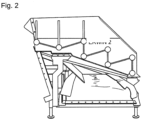
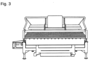
- the screening device is preferably characterized in that the device, as essentially horizontally oriented, separate modules arranged in a vertical sequence from top to bottom, has at least one gravel feeder with a screening deck and a vibration-damped receiving frame according to one of the usage claims and a usable one that can be adapted to different rail widths Chassis includes.
- 'Separate' here means that the individual modules are not materially connected to one another, but rather enclose each other, so that the entire device can be lifted via a bottom frame module and inserted into a track, but each module can also be detached separately - if necessary of comprehensive security systems - can be removed and/or replaced.
- the receiving module and the chassis module are connected via two steel straps (not visible) with several screw holes, whereby the steel straps enable a controlled lateral inclination of the recording module relative to the chassis module when the screws are set at different heights.
- a specifically adjusted inclination allows the cleaning of long curves in the track, where an inclination of the track level against the direction of rotation of the curve would otherwise result in an asymmetrical distribution of the ballast on the sieve grid.
- the present device allows the screen deck to be aligned essentially horizontally and permanently, even in inclined track curves.
- Damping using jet steel balls proved to be particularly advantageous in practical use.
- 'Blast steel balls' refers to a steel granulate that is known in the area of paint removal as a supplement or additive in the compressed air removal of paint using an air-particle mixture. This granulate, consisting of roughly spherical steel particles, proved to be surprisingly superior: While a sand filling provided poorer damping and, in the long run, the inside of the frame tubes was worn down and even worn through in places, blasted steel balls showed better damping with almost no wear on the inner surfaces of the tubes.
Landscapes
- Engineering & Computer Science (AREA)
- Architecture (AREA)
- Civil Engineering (AREA)
- Structural Engineering (AREA)
- Combined Means For Separation Of Solids (AREA)
- Machines For Laying And Maintaining Railways (AREA)
Claims (7)
- Dispositif modulaire de tamisage destiné au nettoyage de ballast de voie pouvant être prélevé du lit de la voie sous le dispositif de tamisage, dans lequel le dispositif de tamisage est conçu sous la forme d'un dispositif pouvant être utilisé dans une voie ferrée et présentant un poids total allant jusqu'à 5 tonnes,comportant un module de plan de tamis susceptible d'entrer en vibration, grâce auquel les impuretés peuvent être séparées du ballast par effet de gravité, dans lequel le module de plan de tamis est disposé dans un module de bâti, dans lequel le dispositif de tamisage comprend en outre des amortisseurs de vibration particulaires, dans lequel le module de plan de tamis est utilisé dans le module de bâti de façon telle que le module de bâti entoure le module de plan de tamis, et dans lequelles amortisseurs de vibration particulaires, comportant au moins un type de particules sélectionné dans le groupe composé de particules minérales naturelles, de particules synthétiques, de sable, de particules métalliques, de billes métalliques, de billes céramiques, de billes synthétiques, d'éléments de remplissage, de billes d'acier ductiles, de particules modifiées en surface, de préférence par une modification thixotrope,sont disposés au niveau de la transition entre le module de plan de tamis et le module de bâti l'entourant, et dans lequel le module de plan de tamis et le module de bâti, à l'état de service, sont découplés, pour ce qui est de la technique vibratoire, par les amortisseurs de vibration particulaires.
- Utilisation d'un dispositif modulaire de tamisage selon la revendication 1 pour nettoyer du ballast prélevé sous le dispositif de tamisage, dans lequel les vibrations du plan de tamis sont amorties par des amortisseurs de vibration particulaires, et le cadre et le module de plan de tamis sont découplés pour ce qui est de la technique vibratoire, le dispositif étant d'autre part utilisé dans une voie ferrée.
- Utilisation selon la revendication 2, caractérisée en ce que le rapport entre la masse de ballast dans le dispositif de tamisage et la masse de particules d'amortissement des vibrations est compris dans la plage de 20 pour 1 à 20 pour 19, de préférence de 15 pour 1 à 15 pour 14, et est maintenu de façon particulièrement préférée à (0,8 +- 0,3) pour (0,2 +- 0,15).
- Utilisation selon la revendication 3, caractérisée en ce que les particules d'amortissement des vibrations sont disposées dans un réservoir de ductilité et de dureté équivalentes, avec un niveau de remplissage, réglable de façon couplée ou individuelle par référence au volume du réservoir, compris entre 30 % et 99 %, de préférence entre 50 % et 90 %, de façon particulièrement préférée égal à 80 % +- 5 %.
- Utilisation selon l'une des revendications 2, 3 et 4, caractérisée en ce que les particules ductiles d'amortissement des vibrations présentent, en tant que particules grossièrement en forme de billes présentant une surface techniquement rugueuse, une taille moyenne comprise dans la gamme de 0,1 à 20 millimètres, de préférence de 0,5 à 10 millimètres, et de façon particulièrement préférée égale à 6 +- 5 millimètres.
- Dispositif modulaire de tamisage selon la revendication 1, caractérisé en ce que le dispositif modulaire de tamisage comprend, en tant que modules séparés, pouvant être utilisés les uns dans les autres, orientés de façon essentiellement horizontale et disposés selon une succession verticale depuis le haut vers le bas, au moins un dispositif d'alimentation en ballast équipé d'un plan de tamis et un cadre de réception à vibrations amorties, ainsi qu'un châssis pouvant être utilisé et adapté en largeur à différentes voies.
- Dispositif modulaire de tamisage selon l'une des revendications 1 ou 6, présentant- un poids à vide de 2,6 +- 0,5 tonnes, et- une capacité de réception maximale de ballast à nettoyer de 0,8 +- 0,3 tonne, et comportant- des modules séparés orientés de façon essentiellement horizontale, les modules comprenant, selon une succession verticale depuis le haut vers le bas, au moinsle dispositif modulaire de tamisage étant conçu pour pouvoir être utilisé et/ou remplacé dans sa totalité et/ou par module.- un module de tamisage, comprenant un dispositif d'alimentation en ballast, un plan de tamis pouvant être mis à vibrer, un entraînement pour générer les vibrations, un dispositif de sortie de ballast, des pieds de support en élastomère et un groupe de régulation raccordé,- un module de réception, comprenant des supports élastomères, une bande de transport/éjection des impuretés déplaçable latéralement vers la gauche et/ou la droite, une construction de bâti tubulaire, des tubes de bâti en acier s'étendant essentiellement à l'horizontale avec une charge en vrac de billes en acier pour tuyère présentant un poids total de billes en acier pour tuyère de 0,2 +- 0,15 tonne, des tubes de bâti s'étendant essentiellement verticalement et présentant une hauteur et/ou une inclinaison réglable(s) de façon séparée et/ou couplée,- un module de châssis, comprenant un système de bâti tubulaire présentant un système d'axes adaptables et remplaçables, un agrégat d'entraînement,
Applications Claiming Priority (1)
| Application Number | Priority Date | Filing Date | Title |
|---|---|---|---|
| DE102013101074.1A DE102013101074B4 (de) | 2013-02-04 | 2013-02-04 | Modulare Siebvorrichtung zur schwerkraftunterstützten Reinigung von unterhalb der Siebvorrichtung entnommenem Gleisschotter |
Publications (4)
| Publication Number | Publication Date |
|---|---|
| EP2762638A2 EP2762638A2 (fr) | 2014-08-06 |
| EP2762638A3 EP2762638A3 (fr) | 2017-01-25 |
| EP2762638B1 true EP2762638B1 (fr) | 2023-12-20 |
| EP2762638C0 EP2762638C0 (fr) | 2023-12-20 |
Family
ID=50002501
Family Applications (1)
| Application Number | Title | Priority Date | Filing Date |
|---|---|---|---|
| EP14151842.3A Active EP2762638B1 (fr) | 2013-02-04 | 2014-01-21 | Dispositif de tamisage modulaire et utilisation d'un dispositif de tamisage modulaire pour nettoyer le ballast d'une voie ferrée |
Country Status (3)
| Country | Link |
|---|---|
| EP (1) | EP2762638B1 (fr) |
| DE (1) | DE102013101074B4 (fr) |
| PL (1) | PL2762638T3 (fr) |
Citations (2)
| Publication number | Priority date | Publication date | Assignee | Title |
|---|---|---|---|---|
| US5199574A (en) * | 1991-10-31 | 1993-04-06 | J & H Equipment, Inc. | Vibrating screen separator |
| DE29702934U1 (de) * | 1997-02-19 | 1997-04-03 | Engelsmann J Ag | Vorrichtung zum Sieben von schüttfähigem Gut |
Family Cites Families (17)
| Publication number | Priority date | Publication date | Assignee | Title |
|---|---|---|---|---|
| DE1162137B (de) * | 1960-05-25 | 1964-01-30 | Barry Controls Inc | Vorgefertigtes lastaufnehmendes Bauelement fuer Bauwerke, Maschinen, Geraete od. dgl. |
| DE2452006C2 (de) | 1974-11-02 | 1982-07-15 | Fa. Carl Freudenberg, 6940 Weinheim | Schwingungsdämpfer |
| US4083775A (en) | 1976-03-05 | 1978-04-11 | Canron, Inc. | Ballast cleaner |
| AT363116B (de) | 1979-01-22 | 1981-07-10 | Plasser Bahnbaumasch Franz | Selbstfahrbare gleisbett-reinigungsmaschine mit hebevorrichtung |
| CH651869A5 (de) * | 1981-03-02 | 1985-10-15 | Canron Inc Crissier | Auf schienen verfahrbare gleisbettreinigungsmaschine. |
| AT374521B (de) * | 1982-08-17 | 1984-05-10 | Plasser Bahnbaumasch Franz | Selbstfahrbare schotterbett-reinigungsmaschine mit einer vibrations-siebanlage |
| DE8506373U1 (de) * | 1985-03-06 | 1985-05-09 | Klüsener, Roswitha, 4300 Essen | Vorrichtung zur Dämpfung von Schwingungen |
| US4706788A (en) * | 1985-04-15 | 1987-11-17 | Melles Griot, Irvine Company | Vibration damped apparatus |
| DE3611234C1 (en) * | 1986-04-04 | 1987-10-08 | Paul Boehringer | Screening machine for the passage of broken rock, scrap, building rubble or recycling material |
| DE3934295A1 (de) * | 1989-10-13 | 1991-04-18 | Paul Boehringer | Siebmaschine fuer den durchlauf von siebgut |
| DE4108252A1 (de) * | 1991-03-14 | 1992-09-17 | Telefunken Systemtechnik | Schwingungsdaempfer fuer mechanische schwingungen |
| CH684433A5 (de) * | 1991-12-11 | 1994-09-15 | Hans Peter Widmer | Verfahren zur Herstellung eines schwingungsgedämpften, rahmenförmigen Gebildes und nach diesem Verfahren hergestelltes rahmenförmiges Gebilde. |
| DE9200743U1 (fr) * | 1992-01-23 | 1992-03-26 | Dinstuhl, Horst, Dipl.-Ing., 4200 Oberhausen, De | |
| DE19533959C2 (de) * | 1995-09-13 | 2001-09-20 | Schneider Walter Gmbh Co Kg | Führungseinrichtung für Mehrwege-Fahrzeuge |
| DE10129083A1 (de) * | 2001-06-15 | 2002-12-19 | Toni Janke | Unterdruckschwingungsdämpfer |
| AT508047A1 (de) * | 2009-03-18 | 2010-10-15 | Univ Wien Tech | Tragkonstruktion |
| DE202012003315U1 (de) * | 2012-03-30 | 2012-04-16 | Simatec Siebmaschinentechnik Gmbh | Siebmaschine zum Klassieren oder Aufbereiten von Kies, Sand oder dergleichen |
-
2013
- 2013-02-04 DE DE102013101074.1A patent/DE102013101074B4/de active Active
-
2014
- 2014-01-21 PL PL14151842.3T patent/PL2762638T3/pl unknown
- 2014-01-21 EP EP14151842.3A patent/EP2762638B1/fr active Active
Patent Citations (2)
| Publication number | Priority date | Publication date | Assignee | Title |
|---|---|---|---|---|
| US5199574A (en) * | 1991-10-31 | 1993-04-06 | J & H Equipment, Inc. | Vibrating screen separator |
| DE29702934U1 (de) * | 1997-02-19 | 1997-04-03 | Engelsmann J Ag | Vorrichtung zum Sieben von schüttfähigem Gut |
Also Published As
| Publication number | Publication date |
|---|---|
| EP2762638A2 (fr) | 2014-08-06 |
| DE102013101074B4 (de) | 2020-12-31 |
| EP2762638C0 (fr) | 2023-12-20 |
| PL2762638T3 (pl) | 2024-03-18 |
| DE102013101074A1 (de) | 2014-08-07 |
| EP2762638A3 (fr) | 2017-01-25 |
Similar Documents
| Publication | Publication Date | Title |
|---|---|---|
| US5322170A (en) | Waste material separating apparatus and method | |
| CN205463139U (zh) | 直线振动筛 | |
| DE102006041989B4 (de) | Siebmaschine insbesondere für schwer trennbare Gemische, wie Schweröl-Sand-Gemische | |
| US9186681B2 (en) | Apparatus for sizing and separating particulate material | |
| US20100012556A1 (en) | Rotating screen material separation system and method | |
| US11247237B2 (en) | Mobile aggregate processing plant | |
| US20170348732A1 (en) | Multi-deck screening assembly | |
| CN208066540U (zh) | 一种碎石筛选装置 | |
| CN211865802U (zh) | 一种建筑施工用筛砂机 | |
| DE3445366C2 (fr) | ||
| JP3966426B1 (ja) | 振動篩装置、篩の網、及び、振動篩方法 | |
| EP2762638B1 (fr) | Dispositif de tamisage modulaire et utilisation d'un dispositif de tamisage modulaire pour nettoyer le ballast d'une voie ferrée | |
| CN115121473B (zh) | 一种混凝土骨料生产用分级筛选设备 | |
| DE202013100489U1 (de) | Verwendung einer modularen Siebvorrichtung zur Reinigung von Gleisschotter und modulare, in ein Gleis einsetzbare Siebvorrichtung | |
| DE102020125280B3 (de) | Schwingsiebmaschine | |
| EP3747555B1 (fr) | Installation mobile de traitement d'agrégat et procédé d'entretien de l'installation mobile de traitement d'agrégat | |
| DE102012108001B4 (de) | Strahlmittelreinigungsanlage | |
| DE4134759A1 (de) | Verfahren und vorrichtung zum sortieren von partikeln nach ihrer kornform | |
| DE3038385A1 (de) | Verfahren und vorrichtung zum abtrennen von staubteilchen von mit diesen behafteten partikeln | |
| DE3328060A1 (de) | Sortiervorrichtung | |
| CN210546344U (zh) | 一种去石机喂料装置 | |
| CN218251439U (zh) | 一种筛沙机 | |
| CN220177488U (zh) | 一种用于喷砂机的砂石过滤装置 | |
| CN218370572U (zh) | 高频筛进料缓冲装置 | |
| CN219507192U (zh) | 一种料仓进料装置 |
Legal Events
| Date | Code | Title | Description |
|---|---|---|---|
| PUAI | Public reference made under article 153(3) epc to a published international application that has entered the european phase |
Free format text: ORIGINAL CODE: 0009012 |
|
| 17P | Request for examination filed |
Effective date: 20140121 |
|
| AK | Designated contracting states |
Kind code of ref document: A2 Designated state(s): AL AT BE BG CH CY CZ DE DK EE ES FI FR GB GR HR HU IE IS IT LI LT LU LV MC MK MT NL NO PL PT RO RS SE SI SK SM TR |
|
| AX | Request for extension of the european patent |
Extension state: BA ME |
|
| PUAL | Search report despatched |
Free format text: ORIGINAL CODE: 0009013 |
|
| AK | Designated contracting states |
Kind code of ref document: A3 Designated state(s): AL AT BE BG CH CY CZ DE DK EE ES FI FR GB GR HR HU IE IS IT LI LT LU LV MC MK MT NL NO PL PT RO RS SE SI SK SM TR |
|
| AX | Request for extension of the european patent |
Extension state: BA ME |
|
| RIC1 | Information provided on ipc code assigned before grant |
Ipc: E01B 27/06 20060101AFI20161222BHEP |
|
| STAA | Information on the status of an ep patent application or granted ep patent |
Free format text: STATUS: REQUEST FOR EXAMINATION WAS MADE |
|
| R17P | Request for examination filed (corrected) |
Effective date: 20170725 |
|
| RBV | Designated contracting states (corrected) |
Designated state(s): AL AT BE BG CH CY CZ DE DK EE ES FI FR GB GR HR HU IE IS IT LI LT LU LV MC MK MT NL NO PL PT RO RS SE SI SK SM TR |
|
| STAA | Information on the status of an ep patent application or granted ep patent |
Free format text: STATUS: EXAMINATION IS IN PROGRESS |
|
| 17Q | First examination report despatched |
Effective date: 20190221 |
|
| STAA | Information on the status of an ep patent application or granted ep patent |
Free format text: STATUS: EXAMINATION IS IN PROGRESS |
|
| STAA | Information on the status of an ep patent application or granted ep patent |
Free format text: STATUS: EXAMINATION IS IN PROGRESS |
|
| GRAP | Despatch of communication of intention to grant a patent |
Free format text: ORIGINAL CODE: EPIDOSNIGR1 |
|
| STAA | Information on the status of an ep patent application or granted ep patent |
Free format text: STATUS: GRANT OF PATENT IS INTENDED |
|
| INTG | Intention to grant announced |
Effective date: 20230711 |
|
| GRAS | Grant fee paid |
Free format text: ORIGINAL CODE: EPIDOSNIGR3 |
|
| GRAA | (expected) grant |
Free format text: ORIGINAL CODE: 0009210 |
|
| STAA | Information on the status of an ep patent application or granted ep patent |
Free format text: STATUS: THE PATENT HAS BEEN GRANTED |
|
| AK | Designated contracting states |
Kind code of ref document: B1 Designated state(s): AL AT BE BG CH CY CZ DE DK EE ES FI FR GB GR HR HU IE IS IT LI LT LU LV MC MK MT NL NO PL PT RO RS SE SI SK SM TR |
|
| REG | Reference to a national code |
Ref country code: GB Ref legal event code: FG4D Free format text: NOT ENGLISH |
|
| REG | Reference to a national code |
Ref country code: CH Ref legal event code: EP |
|
| REG | Reference to a national code |
Ref country code: DE Ref legal event code: R096 Ref document number: 502014016741 Country of ref document: DE |
|
| REG | Reference to a national code |
Ref country code: IE Ref legal event code: FG4D Free format text: LANGUAGE OF EP DOCUMENT: GERMAN |
|
| U01 | Request for unitary effect filed |
Effective date: 20231220 |
|
| U07 | Unitary effect registered |
Designated state(s): AT BE BG DE DK EE FI FR IT LT LU LV MT NL PT SE SI Effective date: 20240109 |
|
| REG | Reference to a national code |
Ref country code: CH Ref legal event code: PK Free format text: BERICHTIGUNGEN |
|
| REG | Reference to a national code |
Ref country code: DE Ref legal event code: R083 Ref document number: 502014016741 Country of ref document: DE |
|
| RIN2 | Information on inventor provided after grant (corrected) |
Inventor name: KLOECKNER, ALEXANDER |
|
| PG25 | Lapsed in a contracting state [announced via postgrant information from national office to epo] |
Ref country code: GR Free format text: LAPSE BECAUSE OF FAILURE TO SUBMIT A TRANSLATION OF THE DESCRIPTION OR TO PAY THE FEE WITHIN THE PRESCRIBED TIME-LIMIT Effective date: 20240321 |
|
| PG25 | Lapsed in a contracting state [announced via postgrant information from national office to epo] |
Ref country code: ES Free format text: LAPSE BECAUSE OF FAILURE TO SUBMIT A TRANSLATION OF THE DESCRIPTION OR TO PAY THE FEE WITHIN THE PRESCRIBED TIME-LIMIT Effective date: 20231220 |
|
| PG25 | Lapsed in a contracting state [announced via postgrant information from national office to epo] |
Ref country code: GR Free format text: LAPSE BECAUSE OF FAILURE TO SUBMIT A TRANSLATION OF THE DESCRIPTION OR TO PAY THE FEE WITHIN THE PRESCRIBED TIME-LIMIT Effective date: 20240321 Ref country code: ES Free format text: LAPSE BECAUSE OF FAILURE TO SUBMIT A TRANSLATION OF THE DESCRIPTION OR TO PAY THE FEE WITHIN THE PRESCRIBED TIME-LIMIT Effective date: 20231220 |
|
| PGFP | Annual fee paid to national office [announced via postgrant information from national office to epo] |
Ref country code: CZ Payment date: 20240208 Year of fee payment: 11 |
|
| U20 | Renewal fee paid [unitary effect] |
Year of fee payment: 11 Effective date: 20240409 |