EP2762638B1 - Modular sieving device and use of a modular sieving device for cleaning railroad track ballast - Google Patents
Modular sieving device and use of a modular sieving device for cleaning railroad track ballast Download PDFInfo
- Publication number
- EP2762638B1 EP2762638B1 EP14151842.3A EP14151842A EP2762638B1 EP 2762638 B1 EP2762638 B1 EP 2762638B1 EP 14151842 A EP14151842 A EP 14151842A EP 2762638 B1 EP2762638 B1 EP 2762638B1
- Authority
- EP
- European Patent Office
- Prior art keywords
- module
- sieve
- vibration
- ballast
- frame
- Prior art date
- Legal status (The legal status is an assumption and is not a legal conclusion. Google has not performed a legal analysis and makes no representation as to the accuracy of the status listed.)
- Active
Links
- 238000004140 cleaning Methods 0.000 title claims description 28
- 238000007873 sieving Methods 0.000 title description 5
- 239000002245 particle Substances 0.000 claims description 23
- 229910000831 Steel Inorganic materials 0.000 claims description 22
- 239000010959 steel Substances 0.000 claims description 22
- 238000013016 damping Methods 0.000 claims description 13
- 229920001971 elastomer Polymers 0.000 claims description 13
- 239000000356 contaminant Substances 0.000 claims description 9
- 239000000806 elastomer Substances 0.000 claims description 9
- 239000004033 plastic Substances 0.000 claims description 6
- 239000004576 sand Substances 0.000 claims description 6
- 239000000919 ceramic Substances 0.000 claims description 3
- 238000010276 construction Methods 0.000 claims description 3
- 230000005484 gravity Effects 0.000 claims description 3
- 229910052500 inorganic mineral Inorganic materials 0.000 claims description 3
- 239000002184 metal Substances 0.000 claims description 3
- 239000002923 metal particle Substances 0.000 claims description 3
- 239000011707 mineral Substances 0.000 claims description 3
- 230000007704 transition Effects 0.000 claims description 3
- 239000000945 filler Substances 0.000 claims description 2
- 239000012798 spherical particle Substances 0.000 claims description 2
- 238000012216 screening Methods 0.000 description 21
- 239000012535 impurity Substances 0.000 description 8
- 238000013461 design Methods 0.000 description 4
- 239000000047 product Substances 0.000 description 4
- 230000002950 deficient Effects 0.000 description 3
- 239000004744 fabric Substances 0.000 description 3
- 238000012423 maintenance Methods 0.000 description 3
- 238000010924 continuous production Methods 0.000 description 2
- 230000008878 coupling Effects 0.000 description 2
- 238000010168 coupling process Methods 0.000 description 2
- 238000005859 coupling reaction Methods 0.000 description 2
- 238000007667 floating Methods 0.000 description 2
- 239000008187 granular material Substances 0.000 description 2
- 238000000034 method Methods 0.000 description 2
- 239000003973 paint Substances 0.000 description 2
- 239000000843 powder Substances 0.000 description 2
- 230000008569 process Effects 0.000 description 2
- 229910001111 Fine metal Inorganic materials 0.000 description 1
- 239000000654 additive Substances 0.000 description 1
- 230000000996 additive effect Effects 0.000 description 1
- 230000000712 assembly Effects 0.000 description 1
- 238000000429 assembly Methods 0.000 description 1
- 230000008859 change Effects 0.000 description 1
- 230000001419 dependent effect Effects 0.000 description 1
- 238000007599 discharging Methods 0.000 description 1
- 238000009826 distribution Methods 0.000 description 1
- 238000005265 energy consumption Methods 0.000 description 1
- 238000005516 engineering process Methods 0.000 description 1
- 230000003116 impacting effect Effects 0.000 description 1
- 238000004519 manufacturing process Methods 0.000 description 1
- 239000000463 material Substances 0.000 description 1
- 239000000203 mixture Substances 0.000 description 1
- 238000012544 monitoring process Methods 0.000 description 1
- 230000003287 optical effect Effects 0.000 description 1
- 238000012856 packing Methods 0.000 description 1
- 230000008439 repair process Effects 0.000 description 1
- 230000035939 shock Effects 0.000 description 1
- 239000013589 supplement Substances 0.000 description 1
- 238000005303 weighing Methods 0.000 description 1
Images

Classifications
-
- E—FIXED CONSTRUCTIONS
- E01—CONSTRUCTION OF ROADS, RAILWAYS, OR BRIDGES
- E01B—PERMANENT WAY; PERMANENT-WAY TOOLS; MACHINES FOR MAKING RAILWAYS OF ALL KINDS
- E01B27/00—Placing, renewing, working, cleaning, or taking-up the ballast, with or without concurrent work on the track; Devices therefor; Packing sleepers
- E01B27/06—Renewing or cleaning the ballast in situ, with or without concurrent work on the track
Definitions
- the present invention is arranged in the field of track ballast cleaning and relates to a modular screening device and the use of the modular screening device for cleaning track ballast that can be removed from a track bed.
- the present invention relates specifically to the area of track ballast cleaning.
- dirt has to be removed from coarse, angular gravel stones.
- the contaminants adhere to the coarse, angular track ballast and have to be removed by massive impacts:
- cleaning track ballast it is removed from the track bed in a small, limited area below the laid track, freed from adhesions and contaminants and returned to the track bed.
- the contaminants are usually loosened from the ballast by impact or shaking pulses, separated and ejected/disposed of outside the track bed.
- the cleaned track ballast - if necessary supplemented with additional fresh ballast - is returned to the track bed, while the cleaning is carried out slowly in a continuous process along a track section.
- Established devices for cleaning track ballast include: B. in the DE 29 45 767 C2 reveals: Bridge-like structures enclose a cleared track bed area a distance of several meters on both sides. Due to the support points being far away from the cleared area, the track sections floating freely without supporting track ballast will only interact insignificantly with the forces and impulses of the device.
- devices are also known in which the feet are extended laterally in order to provide a secure, clearly distant support point for the device. The disadvantage of the latter devices is that they can only be operated in sections and not in a continuous process, which means that the cleaning speed is significantly lower.
- the object of the present invention was therefore to overcome the disadvantages of the prior art and to provide an alternative to the established track ballast cleaning, which, despite its compact design and easier transport, is able to provide sufficient cleaning performance with comparable operating costs.
- an exclusive track ballast weighing up to 5 tons, modular screening device is designed for cleaning track ballast removed from below the screening device.
- a vibrating screen deck module sieves impurities from the gravel using gravity and is arranged in a frame module. The vibrations are taken into account in the design by dampening the vibrations of the screen deck using particulate vibration dampers and decoupling the frame and screen deck module from a vibration point of view.
- the inventors are interested in the use of particulate vibration dampers, such as those in DE 24 52 006 A1 described as an alternative to mechanical vibration dampers is unknown in the area of track bed cleaning.
- the inventors assume that vibration dampers will not be used because they will naturally initially dampen the vibration itself, i.e. one must assume that the vibrations of the screen deck itself will be hindered, which would prevent good cleaning performance.
- the inventors attribute this to the fact that, despite the long-standing need, no use or usable device with the claimed features is known or available on the market.
- the particulate vibration dampers used in the modular sieving device according to the invention have at least one type of particle selected from the group consisting of natural mineral particles, plastic particles, sand, metal particles, metal balls, ceramic balls, plastic balls, packings, ductile steel balls, superficially set - preferably thixotropically set - particles which are arranged in the transition from the screen deck module to the enclosing frame module, with the screen deck module and frame module being decoupled in terms of vibration technology by the particulate vibration dampers.
- the assemblies are decoupled surprisingly effectively: the vibrations of the screen deck are at best transmitted to the rest of the device in a damped manner with a significantly more diffuse, softer impulse. This trick made it possible for the first time to provide a light, compact screening device for cleaning track ballast, which offers the advantages of a compact design in combination with good cleaning performance.
- modules are also designed to be 'insertable' into one another and - depending on the module combination - can be combined by adapting the mutual support points.
- both the individual modules and the device as a whole can be used and exchanged, so that performance characteristics and dimensions of the device are advantageously provided in a versatile manner.
- Coupling adapters advantageously allow the device to be coupled to systems available on site, provided that the device is designed/used without its own drive unit.
- the use is preferably characterized in that the ratio of mass of gravel in the screening device to mass of vibration-damping particles is in the range 20 to 1 to 20 to 19, preferably 15 to 1 to 15 to 14, particularly preferably around (0.8 +- 0, 3) is held to (0.2 +-0.15).
- the use is preferably characterized in that the vibration-damping, ductile particles, as roughly spherical particles with a technically rough surface, have an average size in the range 0.1 to 20 millimeters, preferably 0.5 to 10 millimeters, particularly preferably 6 + - 5 millimeters .
- the screening device is preferably characterized in that the device, as essentially horizontally oriented, separate modules arranged in a vertical sequence from top to bottom, has at least one gravel feeder with a screening deck and a vibration-damped receiving frame according to one of the usage claims and a usable one that can be adapted to different rail widths Chassis includes.
- 'Separate' here means that the individual modules are not materially connected to one another, but rather enclose each other, so that the entire device can be lifted via a bottom frame module and inserted into a track, but each module can also be detached separately - if necessary of comprehensive security systems - can be removed and/or replaced.
- the receiving module and the chassis module are connected via two steel straps (not visible) with several screw holes, whereby the steel straps enable a controlled lateral inclination of the recording module relative to the chassis module when the screws are set at different heights.
- a specifically adjusted inclination allows the cleaning of long curves in the track, where an inclination of the track level against the direction of rotation of the curve would otherwise result in an asymmetrical distribution of the ballast on the sieve grid.
- the present device allows the screen deck to be aligned essentially horizontally and permanently, even in inclined track curves.
- Damping using jet steel balls proved to be particularly advantageous in practical use.
- 'Blast steel balls' refers to a steel granulate that is known in the area of paint removal as a supplement or additive in the compressed air removal of paint using an air-particle mixture. This granulate, consisting of roughly spherical steel particles, proved to be surprisingly superior: While a sand filling provided poorer damping and, in the long run, the inside of the frame tubes was worn down and even worn through in places, blasted steel balls showed better damping with almost no wear on the inner surfaces of the tubes.
Description
Die vorliegende Erfindung ist im Bereich der Gleisschotter-Reinigung angeordnet und betrifft eine modulare Siebvorrichtungen und die Verwendung der modularen Siebvorrichtung zur Reinigung von aus einem Gleisbett entnehmbaren Gleisschotter.The present invention is arranged in the field of track ballast cleaning and relates to a modular screening device and the use of the modular screening device for cleaning track ballast that can be removed from a track bed.
Allgemeine Siebvorrichtungen sind als Teil von ortsfesten Klassiermaschinen schon lange bekannt; so offenbart die
Die vorliegende Erfindung betrifft spezifisch den Bereich der Gleisschotter-Reinigung. Entgegengesetzt zu den Sieb-Verfahren zur Produkt-Klassierung müssen hier grobestückige, kantige Schottersteine von Schmutz befreit werden. Die Verunreinigungen haften an dem grobstückigen, kantigen Gleisschotter an und müssen durch massive Stöße abgelöst werden: Bei der Reinigung von Gleisschotter wird dieser unterhalb des verlegten Gleises in kleinem, begrenztem Areal dem Gleisbett entnommen, von Anhaftungen und Verunreinigungen befreit und wieder in das Gleisbett zurückgeführt. Die Verunreinigungen werden dabei üblicher Weise durch Schlag- oder Rüttel-Impulse von dem Schotter gelöst, abgetrennt und außerhalb des Gleisbetts ausgeworfen / entsorgt. Der gereinigte Gleisschotter wird - ggf. mit zusätzlichem, frischem Schotter ergänzt - wieder in das Gleisbett zurückgeführt, während die Reinigung in einem kontinuierlichen Verfahren langsam eine Gleisstrecke abfahrend durchgeführt wird.The present invention relates specifically to the area of track ballast cleaning. In contrast to the sieving process for product classification, dirt has to be removed from coarse, angular gravel stones. The contaminants adhere to the coarse, angular track ballast and have to be removed by massive impacts: When cleaning track ballast, it is removed from the track bed in a small, limited area below the laid track, freed from adhesions and contaminants and returned to the track bed. The contaminants are usually loosened from the ballast by impact or shaking pulses, separated and ejected/disposed of outside the track bed. The cleaned track ballast - if necessary supplemented with additional fresh ballast - is returned to the track bed, while the cleaning is carried out slowly in a continuous process along a track section.
Etablierte Vorrichtungen zur Reinigung von Gleisschotter sind z. B. in der
Nachteilig ist bei den etablierten Vorrichtungen für kontinuierliche Reinigung, dass diese naturgemäß ein sehr hohes Gewicht von zig Tonnen aufweisen. Deshalb sind solche Vorrichtungen als feste Zugsysteme ausgebildet, welche auf den Schienen direkt zu dem zu reinigenden Abschnitt gefahren werden müssen. Die Leihgebühren fallen ob der notwendigen An-und Abfahrt und der notwendigen Wartung der Großmaschine entsprechend hoch aus.The disadvantage of the established devices for continuous cleaning is that they naturally have a very high weight of tens of tons. Therefore, such devices are designed as fixed train systems, which have to be driven on the rails directly to the section to be cleaned. The rental fees are correspondingly high due to the necessary arrival and departure and the necessary maintenance of the large machine.
Vor diesem Hintergrund hat es durchaus Ansätze gegeben, Gleisbettreinigungsvorrichtungen kompakter und leichter auszubilden, damit die Vorrichtung über straßentaugliche Anhänger-Systeme geliefert und vor Ort direkt verwendet werden kann. Dabei ergibt sich aber das Problem, dass eine kürzere, höhere Vorrichtung Auflagepunkte nahe zum freigeräumten Bereich aufweist: Gewicht und Schwingungen übertragen sich auf die frei schwebenden Gleisabschnitte. Die dann mitschwingenden Gleisabschnitte lassen die gesamte Vorrichtung elastisch auf- und abschwingen. Der auf einem Rüttelsieb aufgelegte Gleisschotter erfährt dadurch kaum mehr Impulse; er bleibt auf dem Sieb ohne nennenswerte Erschütterung liegen, wodurch Reinigungsleistung und Durchsatzmenge drastisch verschlechtert werden. Ein schwerkraftuntertütztes, schräg ausgerichtetes Rüttelsieb, auf dem Gleisschotter mit jedem Impuls in abfallender Richtung unter Abtrennung der Verunreinigungen weiterwandert, kann dann nicht mehr sinnvoll verwendet werden.Against this background, there have been attempts to make track bed cleaning devices more compact and lighter so that the device can be delivered via road-compatible trailer systems and used directly on site. However, the problem arises that a shorter, higher device has support points close to the cleared area: weight and vibrations are transferred to the free-floating track sections. The track sections that then resonate cause the entire device to swing up and down elastically. As a result, the track ballast placed on a vibrating screen hardly experiences any impulses; it remains on the sieve without any significant vibration, which drastically reduces cleaning performance and throughput. A gravity-assisted, obliquely aligned vibrating screen on which track ballast moves in a downward direction with each impulse, separating out the impurities, can then no longer be used sensibly.
Alternativ zu etablierten Rüttel- und Impuls-Verfahren sieht die
Aufgabe der vorliegenden Erfindung war es daher, die Nachteile des Standes der Technik zu überwinden und eine Alternative zur etablierten Gleisschotter-Reinigung bereitzustellen, welche trotz kompakter Bauweise und einfacherem Transport eine ausreichende Reinigungsleistung bei vergleichbaren Betriebskosten bereitzustellen vermag.The object of the present invention was therefore to overcome the disadvantages of the prior art and to provide an alternative to the established track ballast cleaning, which, despite its compact design and easier transport, is able to provide sufficient cleaning performance with comparable operating costs.
Die Lösung dieser Aufgabe erfolgt gemäß der Merkmale der unabhängigen Ansprüche. Vorteilhafte Ausführungsformen ergeben sich aus den abhängigen Ansprüchen sowie der nachfolgenden Beschreibung.This problem is solved in accordance with the features of the independent claims. Advantageous embodiments result from the dependent claims and the following description.
Erfindungsgemäß ist eine exklusive Gleisschotter bis zu 5 Tonnen schwere, modulare Siebvorrichtung zur Reinigung von unterhalb der Siebvorrichtung entnommenem Gleisschotter ausgebildet. Hierbei siebt ein vibrierendes Siebdeck-Modul schwerkraftunterstützt Verunreinigungen von dem Schotter ab und ist in einem Rahmen-Modul angeordnet. Die Schwingungen werden konstruktiv dadurch berücksichtigt, dass die Vibrationen des Siebdecks durch partikuläre Schwingungsdämpfer gedämpft und Rahmen und Siebdeck-Modul schwingungstechnisch entkoppelt werden.According to the invention, an exclusive track ballast weighing up to 5 tons, modular screening device is designed for cleaning track ballast removed from below the screening device. Here, a vibrating screen deck module sieves impurities from the gravel using gravity and is arranged in a frame module. The vibrations are taken into account in the design by dampening the vibrations of the screen deck using particulate vibration dampers and decoupling the frame and screen deck module from a vibration point of view.
Den Erfindern ist die Verwendung partikulärer Schwingungsdämpfer, wie sie beispielsweise in der
Die in der erfindungsgemäßen modulare Siebvorrichtung verwendeten partikulären Schwingungsdämpfer weisen mindestens eine Partikelsorte ausgewählt aus der Gruppe bestehend aus natürlichen Mineralpartikeln, Kunststoffpartikeln, Sand, Metallpartikeln, Metallkugeln, Keramikkugeln, Kunststoffkugeln, Füllkörpern, duktilen Stahlkugeln, oberflächlich eingestellten - bevorzugt thixotrop eingestellten - Partikeln auf, die im Übergang von Siebdeck-Modul zum umschließenden Rahmen-Modul angeordnet sind, wobei Siebdeck-Modul und Rahmen-Modul durch die partikularen Schwingungsdämpfer schwingungstechnisch entkoppelt sind.The particulate vibration dampers used in the modular sieving device according to the invention have at least one type of particle selected from the group consisting of natural mineral particles, plastic particles, sand, metal particles, metal balls, ceramic balls, plastic balls, packings, ductile steel balls, superficially set - preferably thixotropically set - particles which are arranged in the transition from the screen deck module to the enclosing frame module, with the screen deck module and frame module being decoupled in terms of vibration technology by the particulate vibration dampers.
Durch Verwendung der partikulären Schwingungsdämpfung im Übergang von Siebdeck-Modul zum umschließenden Rahmen-Modul werden die Baugruppen überraschend wirksam entkoppelt: Die Vibrationen des Siebdecks übertragen sich allenfalls noch gedämpft mit deutlich diffuserem, weicherem Impuls auf die restliche Vorrichtung. Durch diesen Kunstgriff gelang es erstmals, eine leichte, kompakte Siebvorrichtung für die Gleisschotter-Reinigung bereitzustellen, welche die Vorteile eines kompakten Designs in Kombination mit guter Reinigungsleistung bereitstellt.By using particulate vibration damping in the transition from the screen deck module to the enclosing frame module, the assemblies are decoupled surprisingly effectively: the vibrations of the screen deck are at best transmitted to the rest of the device in a damped manner with a significantly more diffuse, softer impulse. This trick made it possible for the first time to provide a light, compact screening device for cleaning track ballast, which offers the advantages of a compact design in combination with good cleaning performance.
Weiterhin offenbart die vorliegende Erfindung die Verwendung der modularen Siebvorrichtung zur Reinigung des unterhalb der Siebvorrichtung entnommenen Gleisschotters wobei die Siebvorrichtung als in ein Gleis einsetzbare Vorrichtung mit einem Gesamtgewicht von - exklusive Gleisschotter - bis zu 5 Tonnen ausgebildet ist. 'einsetzbar' bedeutet hierbei, dass die Vorrichtung in ein vorhandenes Gleis-System eingesetzt werden kann, um dann vor Ort unter kontinuierlicher Reinigung des Gleisschotters über die zu reinigenden Abschnitte gefahren zu werden. Es versteht sich, dass Achs-Systeme hierbei vor Ort auf das jeweilige Gleissystem angepasst werden können, um die Verfahrbarkeit über das vorhandene, zu bearbeitende Gleis zu ermöglichen. Durch ineinander einsetzbare Module wird eine Wartung bei Defekt eines Moduls erheblich vereinfacht: Die Module sind austauschbar, d. h. man kann das defekte Modul direkt durch ein funktionierendes ersetzen, ohne umständlich stoffliche Verbindungen wie Verschweißungen trennen zu müssen. Anschließend kann das defekte Modul gesondert in einer Werkstatt repariert werden. Ausfallzeiten werden so minimiert und Reparaturmaßnahmen können bei deutlich verringerten Transportkosten optimiert in einer zentralen Werkstatt vorgenommen werden. Es versteht sich, dass dabei auch Module ineinander 'einsetzbar' ausgebildet sind und - je nach Modulkombination - unter Anpassung der wechselseitigen Auflagepunkte kombiniert werden können. Besonders vorteilhaft sind dabei sowohl die einzelnen Module als auch die Vorrichtung als Ganzes einsetzbar und austauschbar, sodass Leistungsmerkmale und auch Maße der Vorrichtung vorteilhaft vielseitig anpassbar bereitgestellt werden. Kupplungs-Adapter erlauben vorteilhaft die Ankuppelung der Vorrichtung an vor Ort verfügbare Systeme, sofern die Vorrichtung ohne eigenes Antriebsaggregat ausgebildet ist / verwendet wird.Furthermore, the present invention discloses the use of the modular screening device for cleaning the track ballast removed from below the screening device, the screening device being designed as a device that can be inserted into a track with a total weight of - excluding track ballast - up to 5 tons. 'Usable' means that the device can be inserted into an existing track system and then driven on site over the sections to be cleaned while continuously cleaning the track ballast. It goes without saying that axle systems can be adapted to the respective track system on site in order to enable movement over the existing track to be processed. Modules that can be inserted into one another make maintenance considerably easier if a module is defective: the modules are interchangeable, i.e. H. You can replace the defective module directly with a functioning one without having to laboriously separate material connections such as welds. The defective module can then be repaired separately in a workshop. Downtimes are minimized and repair measures can be carried out in a central workshop in an optimized manner with significantly reduced transport costs. It goes without saying that modules are also designed to be 'insertable' into one another and - depending on the module combination - can be combined by adapting the mutual support points. Particularly advantageously, both the individual modules and the device as a whole can be used and exchanged, so that performance characteristics and dimensions of the device are advantageously provided in a versatile manner. Coupling adapters advantageously allow the device to be coupled to systems available on site, provided that the device is designed/used without its own drive unit.
Bevorzugt ist die Verwendung dadurch gekennzeichnet, dass das Verhältnis Masse Schotter in der Siebvorrichtung zu Masse an schwingungsdämpfenden Partikeln im Bereich 20 zu 1 bis 20 zu 19, bevorzugt 15 zu 1 bis 15 zu 14, besonders bevorzugt um (0,8 +- 0,3) zu (0,2 +-0,15) gehalten ist.The use is preferably characterized in that the ratio of mass of gravel in the screening device to mass of vibration-damping particles is in the range 20 to 1 to 20 to 19, preferably 15 to 1 to 15 to 14, particularly preferably around (0.8 +- 0, 3) is held to (0.2 +-0.15).
Bevorzugt ist die Verwendung dadurch gekennzeichnet, dass die schwingungsdämpfenden Partikel mindestens eine Partikelsorte umfassen, die Partikelsorte ausgewählt aus der Gruppe bestehend aus natürlichen Mineralpartikeln, Kunststoffpartikeln, Sand, Metallpartikeln, Metallkugeln, Keramikkugeln, Kunststoffkugeln, Füllkörpern, duktilen Stahlkugeln, oberflächlich eingestellten - bevorzugt thixotrop eingestellten - Partikeln.The use is preferably characterized in that the vibration-damping particles comprise at least one type of particle, the particle type selected from the group consisting of natural mineral particles, plastic particles, sand, metal particles, metal balls, ceramic balls, plastic balls, fillers, ductile steel balls, superficially set - preferably thixotropically set - particles.
Bevorzugt ist die Verwendung dadurch gekennzeichnet, dass die schwingungsdämpfenden Partikel in einem Behälter mit gleicher Duktilität und Härte mit einem gekoppelt oder einzeln regelbaren Füllgrad in Bezug auf das Behältervolumen von 30% bis 99%, bevorzugt 50% bis 90%, besonders bevorzugt 80% +- 5%, angeordnet werden.The use is preferably characterized in that the vibration-damping particles are coupled or individually in a container with the same ductility and hardness adjustable degree of filling in relation to the container volume of 30% to 99%, preferably 50% to 90%, particularly preferably 80% +- 5%.
Bevorzugt ist die Verwendung dadurch gekennzeichnet, dass die schwingungsdämpfenden, duktilen Partikel als grob kugelförmige Partikel mit technisch rauher Oberfläche eine mittlere Größe im Bereich 0,1 bis 20 Millimeter, bevorzugt 0,5 bis 10 Millimeter, besonders bevorzugt 6 +- 5 Millimeter, aufweisen.The use is preferably characterized in that the vibration-damping, ductile particles, as roughly spherical particles with a technically rough surface, have an average size in the range 0.1 to 20 millimeters, preferably 0.5 to 10 millimeters, particularly preferably 6 + - 5 millimeters .
Bevorzugt ist die modulare Siebvorrichtung zur Reinigung des unterhalb der Siebvorrichtung entnommenen Gleisschotters gemäß der beanspruchten Verwendung dadurch gekennzeichnet, dass die Siebvorrichtung als in ein Gleis einsetzbare Vorrichtung mit einem Gesamtgewicht von 1,5 bis 3,5 Tonnen, besonders bevorzugt 2,6 +- 0,5 Tonnen, ausgebildet ist.According to the claimed use, the modular screening device for cleaning the track ballast removed from below the screening device is preferably characterized in that the screening device is a device that can be inserted into a track and has a total weight of 1.5 to 3.5 tons, particularly preferably 2.6 +- 0 .5 tons.
Bevorzugt ist die Siebvorrichtung dadurch gekennzeichnet, dass die Vorrichtung als im Wesentlichen horizontal ausgerichtete, in vertikaler Abfolge von oben nach unten angeordnete, separate Module zumindest eine Schotteraufgabe mit Siebdeck und einen vibrationsgedämpften Aufnahme-Rahmen gemäß einem der Verwendungsansprüche und ein an verschiedene Schienenbreiten anpassbares, einsetzbares Fahrgestell umfasst. 'separat' bedeutet hierbei, dass die einzelnen Module nicht stofflich miteinander verbunden sind, sondern allenfalls einander umschließen, sodass die gesamte Vorrichtung zwar über ein unterstes Rahmenmodul hochgehoben und in ein Gleis eingesetzt werden kann, aber jedes Modul für sich gleichfalls - ggf. nach lösen von übergreifenden Sicherungseinrichtungen - entnommen und/oder ausgetauscht werden kann.The screening device is preferably characterized in that the device, as essentially horizontally oriented, separate modules arranged in a vertical sequence from top to bottom, has at least one gravel feeder with a screening deck and a vibration-damped receiving frame according to one of the usage claims and a usable one that can be adapted to different rail widths Chassis includes. 'Separate' here means that the individual modules are not materially connected to one another, but rather enclose each other, so that the entire device can be lifted via a bottom frame module and inserted into a track, but each module can also be detached separately - if necessary of comprehensive security systems - can be removed and/or replaced.
Optional ist die Siebvorrichtung dadurch gekennzeichnet, dass die Siebvorrichtung weiterhin mindestens eine zusätzliche Baugruppe aufweist, die zusätzliche Baugruppe ausgewählt aus der Gruppe bestehend aus Federlagerung, Antriebsaggregat, Vibrationswelle, Schotter-Aufnahme, Schotter-Förderer, Schotter-Abgabe, optischem Überwachungsmodul, auswertender Regelbaugruppe, Sensor-Baugruppe, seitlichem Abwurfschacht, vorder- und/oder rückseitigem Abwurfschacht, Masse-Integrator, Schwingungssensor, Vibrations-Generator, Schotter-abgabe-Steuerung, Förderband, Elastomer-Auflagen, Elastomer-Standfüßen, Elastomer-Köpfen, einzeln und/oder gekoppelt höhenverstellbare Aufnahmelager, Neigungs-und/oder Pendel-Regelung, Rohrrahmensystem, horizontal erstreckte Rahmenrohre mit Partikel-Füllung, auf Links- oder Rechtslauf einstellbare Förderband-Antriebe, links- und/oder rechtsseitig ausfahrbare Auswurf-Förderbänder.Optionally, the screening device is characterized in that the screening device further has at least one additional assembly, the additional assembly selected from the group consisting of spring bearing, drive unit, vibration shaft, ballast pickup, ballast conveyor, ballast delivery, optical monitoring module, evaluating control assembly, Sensor assembly, side discharge chute, front and/or rear discharge chute, mass integrator, vibration sensor, vibration generator, ballast discharge control, conveyor belt, elastomer pads, elastomer feet, elastomer heads, individually and/or coupled Height-adjustable support bearings, inclination and/or pendulum control, tubular frame system, horizontally extended frame tubes with particle filling, conveyor belt drives that can be adjusted to run left or right, ejection conveyor belts that can be extended on the left and/or right side.
Weitere Vorteile ergeben sich aus den Ausführungsbeispielen. Es versteht sich, dass die vorbeschriebenen Merkmale und Vorteile und nachfolgenden Ausführungsbeispiele nicht beschränkend aufzufassen sind. Vorteilhafte, zusätzliche Merkmale und zusätzliche Merkmalskombinationen, wie sie in der Beschreibung erläutert sind, können im Rahmen der Ansprüche kombiniert verwirklicht werden.Further advantages result from the exemplary embodiments. It is understood that the features and advantages described above and the following exemplary embodiments are not limiting are to be understood. Advantageous, additional features and additional combinations of features, as explained in the description, can be implemented in combination within the scope of the claims.
Die Figuren veranschaulichen an Hand von Prinzipbildern:
-
Fig. 1 aufnahmeseitige Ansicht einer Ausführungsform mit von vorne betrachtet nach rechts auskragendem Auswurf-Förderband für Verunreinigungen, -
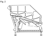
Fig. 2 Seitenansicht der Ausführungsform gemäßFig. 1 , veranschaulichend die Seite zu welcher die Verunreinigungen ausgeworfen werden, -
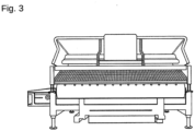
Fig. 3 abgabeseitige Ansicht der Ausführungsform gemäß derFiguren 1 und2 , welche ein schräg zur Abgabeseite abfallendes Siebgitter erkennen lässt.
-
Fig. 1 Receiving side view of an embodiment with an ejection conveyor belt for impurities cantilevered to the right when viewed from the front, -
Fig. 2 Side view of the embodiment according toFig. 1 , illustrating the side to which the impurities are ejected, -
Fig. 3 Delivery side view of the embodiment according toFigures 1 and2 , which reveals a sieve grid that slopes diagonally towards the delivery side.
Der seitlich auskragende, rechtwinkelige Rohr-Rahmen mit außenseitigen, höhenverstellbaren Standfüßen, LED-Leuchtmodulen und zwei Regelbaugruppen nebst Stromanschlüssen bildet ein Aufnahmemodul, welches das zur Seite auskragende Auswurf-Förderband zur Abgabe der Verunreinigungen umfasst. Die außenseitigen Standfüße sind ausfahrbar und können im Falle eines Spurwechsels der Gleisspurbreite die Vorrichtung abstützen, damit unterseitig Räder und/oder Achsen im Abstand angepasst werden können. Unterseitg schließt sich an das Rohr-Rahmengestell des Aufnahmemoduls das bereits erwähnte Fahrgestell-Modul an.The cantilevered, rectangular tubular frame with external, height-adjustable feet, LED lighting modules and two control modules along with power connections forms a receiving module, which includes the ejection conveyor belt that projects to the side for discharging the contaminants. The outside feet are extendable and can support the device in the event of a change in track width, so that the distance between the wheels and/or axles can be adjusted on the underside. Bottom closes The chassis module already mentioned is attached to the tubular frame of the receiving module.
Aufnahme-Modul und Fahrgestell-Modul sind über zwei Stahllaschen (nicht sichtbar) mit mehreren Schraublöchern verbunden, wobei die Stahl-Laschen bei unterschiedlich hoch angesetzter Verschraubung eine gesteuerte Seitenneigung des Aufnahme-Moduls gegenüber dem Fahrgestell-Modul ermöglichen. Eine gezielt eingestellt Neigung erlaubt das Reinigen von langezogenen Kurven im Gleisverlauf, bei denen eine Neigung des Gleis-Niveaus gegen den Drehsinn der Kurve sonst eine asymmetrische Verteilung des Schotters auf dem Sieb-Gitter zur Folge haben würde. So erlaubt die vorliegende Vorrichtung eine im wesentlichen horizontal gehaltene, dauerhafte Ausrichtung des Siebdecks auch in geneigten Gleis-Kurven.The receiving module and the chassis module are connected via two steel straps (not visible) with several screw holes, whereby the steel straps enable a controlled lateral inclination of the recording module relative to the chassis module when the screws are set at different heights. A specifically adjusted inclination allows the cleaning of long curves in the track, where an inclination of the track level against the direction of rotation of the curve would otherwise result in an asymmetrical distribution of the ballast on the sieve grid. The present device allows the screen deck to be aligned essentially horizontally and permanently, even in inclined track curves.
Im Betrieb wird das Siebdeck gepulsten Erschütterungen unterworfen, welche den Schotter auf dem Sieb-Gitter tanzen und in Richtung der Ausgabe vorrücken lassen. Die dabei abfallenden Verunreinigungen werden auf das Auswurf-Förderband geleitet und seitlich ausgeworfen.During operation, the screen deck is subjected to pulsed vibrations, which cause the gravel to dance on the screen grid and advance towards the output. The ones that fall off Impurities are directed onto the ejection conveyor belt and ejected to the side.
Die Dämpfung erfolgt in den horizontal erstreckten, unterseitigen Rohren des Rohr-Rahmengestells des Aufnahme-Moduls: Rund 170 Kilogramm (+- 50 Kilogramm) an Strahl-Stahlkugeln liegen in loser Schüttung in diesen Rohren und dämpfen wie vorbeschrieben die Vibrationen, die durch die Erschütterungen des Siebdecks / Sieb-Gitters bei einer Beladung mit ca. 500 kg Schotter anfallen. Obwohl in dieser Ausführungsform die gesamte Anlage zur Reinigung direkt über dem freigeräumten Bereich angeordnet ist, kann eine Reinigung mit einem überraschend hohen Durchsatz und guter Wirksamkeit durchgeführt werden.The damping takes place in the horizontally extended, underside tubes of the tube frame of the receiving module: around 170 kilograms (+- 50 kilograms) of jet steel balls lie in bulk in these tubes and dampen the vibrations caused by the shocks as described above of the sieve deck / sieve grid when loaded with approx. 500 kg of gravel. Although in this embodiment the entire cleaning system is arranged directly above the cleared area, cleaning can be carried out with a surprisingly high throughput and good effectiveness.
Gegen die üblichen Leihgebühren der etablierten Großmaschinen gerechnet spielte die in den Figuren veranschaulichte Ausführungsform bereits innerhalb weniger Monate Betrieb inklusive Verschleiß und üblichen Wartungen komplett ihre Herstellungskosten wieder ein.Calculated against the usual rental fees for established large machines, the embodiment illustrated in the figures completely recouped its manufacturing costs within just a few months of operation, including wear and tear and usual maintenance.
Als besonders vorteilhaft erwies sich in der praktischen Anwendung die Dämpfung mittels Strahlstahl-Kugeln. 'Strahlstahl-Kugeln' bezeichnet hierbei ein Stahlgranulat, dass im Bereich der Lack-Entfernung als Zuschlag oder Zusatz bei der Druckluft-Entfernung von Lack mittels Luft-Partikel-Gemisch bekannt ist. Dieses aus grob kugelförmigen Stahlpartikeln bestehende Granulat erwies sich als überraschend überlegen:
Während eine Sandfüllung eine schlechtere Dämpfung bereitstellte und auf Dauer die Rahmen-Rohre innenseitig ab- und stellenweise sogar durchschliff, zeigten Strahlstahl-Kugeln bessere Dämpfung bei so gut wie keinem Verschleiß der Rohr-Innenflächen. Die Erfinder führen dies auf die Stahlelastizität, sphärische Morphologie und vergleichbare Härte der Strahlstahl-Kugeln zurück: Zum einen ist der Reibkontakt der Kugeln mit einem Stahlrohr so gut wie verschleißfrei und zum anderen werden die Kugeln an ihren Auflagepunkten in Gruppe elastisch bei auftreffendem Impuls deformiert und speichern so einen Teil der Impulsenergie, der anschließend bei der Rückkehr in die Ausgangsform zeitlich verzögert wieder freigesetzt wird. Sand hingegen neigt zu sprödem Bruch, welcher harte, scharfe Kanten erzeugt, die wiederum die Rohrfläche abrasiv bei dem nächsten, auftreffenden Impuls beschädigen. Zudem vermag kristalliner Sand kaum eine elastische Kompensation bereitzustellen, was die schlechteren Dämpfungs-Eigenschaften mit erklären kann.Damping using jet steel balls proved to be particularly advantageous in practical use. 'Blast steel balls' refers to a steel granulate that is known in the area of paint removal as a supplement or additive in the compressed air removal of paint using an air-particle mixture. This granulate, consisting of roughly spherical steel particles, proved to be surprisingly superior:
While a sand filling provided poorer damping and, in the long run, the inside of the frame tubes was worn down and even worn through in places, blasted steel balls showed better damping with almost no wear on the inner surfaces of the tubes. The inventors attribute this to the steel elasticity, spherical morphology and comparable hardness of the jet steel balls: On the one hand, the frictional contact of the balls with a steel tube is virtually wear-free and, on the other hand, the balls are elastically deformed in a group at their contact points when the impulse hits them In this way, part of the impulse energy is stored, which is then released again with a time delay when it returns to its original form. Sand, on the other hand, is prone to brittle fracture, which creates hard, sharp edges that in turn abrasive damage to the pipe surface with the next impacting impulse. In addition, crystalline sand is hardly able to provide elastic compensation, which can explain the poorer damping properties.
In besonders vorteilhafter Ausführungsform weist die modulare Siebvorrichtung
ein Leergewicht von 2,6 +- 0,5 Tonnen und- eine maximale Aufnahmekapazität für zu reinigenden Schotter im Bereich von 0,8 +- 0,3 Tonnen auf, wobei
- im Wesentlichen horizontal ausgerichtete, separate Module in vertikaler Abfolge von oben nach unten zumindest umfassen:
- ein Siebmodul, umfassend eine Schotteraufgabe, ein rüttelbares Siebdeck, Rüttel-Antrieb, Schotter-Ausgabe, Elastomer-Standfüße und eine angeschlossene Regelbaugruppe,
- ein Aufnahme-Modul, umfassend Elastomer-Auflagen, ein seitlich links und/oder rechts ausfahrbares Verunreinigungs-Auswurf-Förderband, eine Rohrrahmen-Konstruktion, im Wesentlichen horizontal erstreckte Stahl-Rahmen-Rohre mit einer losen Strahlstahl-Kugelfüllung mit einem Gesamtgewicht der Strahlstahl-Kugeln
im Bereich von 0,2 +- 0,15 Tonnen, im Wesentlichen vertikal erstreckte Rahmen-Rohre mit einzeln und/oder gekoppelt verstellbarer Höhe und/oder Neigung, - ein Fahrgestell-Modul, umfassend ein Rohrrahmensystem mit austauschbarem, anpassbarem Achs-System, Antriebsaggregat und Kupplungs-Adapter,
- wobei die modulare Siebvorrichtung insgesamt und/oder modulweise austauschbar und/oder einsetzbar ausgebildet ist.
- an empty weight of 2.6 +- 0.5 tons and
- a maximum holding capacity for gravel to be cleaned in the range of 0.8 +- 0.3 tons, whereby
- Substantially horizontally oriented, separate modules in a vertical sequence from top to bottom at least include:
- a sieve module, comprising a gravel feeder, a shakeable sieve deck, shaker drive, gravel dispenser, elastomer feet and a connected control assembly,
- a receiving module comprising elastomer supports, a contaminant ejection conveyor belt that can be extended to the left and/or right, a tubular frame construction, essentially horizontally extended steel frame tubes with a loose blast steel ball filling with a total weight of the blast steel Balls in the range of 0.2 +- 0.15 tons, essentially vertically extended frame tubes with individually and/or coupled adjustable height and/or inclination,
- a chassis module comprising a tubular frame system with an exchangeable, adaptable axle system, drive unit and coupling adapter,
- wherein the modular screening device is designed to be interchangeable and/or usable as a whole and/or in modules.
Claims (7)
- A modular sieve device for cleaning track ballast that can be removed from a track bed underneath the sieve device, whereby the sieve device is designed as a device with a total weight of up to 5 tons that can be inserted into a track,comprising a vibration-capable sieve deck module with which contaminants can be sieved from the track ballast using gravity, whereby the sieve deck module is arranged in a frame module, whereby the sieve device furthermorehas particulate vibration dampers, whereby the sieve deck module is inserted into the frame module in such a way that the frame module encloses the sieve deck module and whereby the particulate vibration dampers, comprising at least one type of particle selected from the group consisting of natural mineral particles, plastic particles, sand, metal particles, metal balls, ceramic balls, plastic balls, fillers, ductile steel balls, superficially set, preferentially thixotropically set, particles,are arranged in the transition from the sieve deck module to the enclosing frame module, and whereby, in the operating state, the sieve deck module and the frame module are decoupled from vibration by the particulate vibration dampers.
- Application of a modular sieve device according to Claim 1 for cleaning of track ballast removed from under the sieve device, whereby the vibrations of the sieve deck are dampened by particulate vibration dampers and the frame and sieve deck module are vibration decoupled, whereby the device is inserted into a track.
- Application according to Claim 2 characterized in that the ratio of mass of ballast in the sieve device to the mass of vibration-damping particles is in the range of 20:1 to 20:19, preferably 15:1 to 15:14, particularly preferably about (0.8 ± 0.3) to (0.2 ± 0.15).
- Application according to Claim 3 characterized in that the vibration-damping particles are arranged in a container with the same ductility and hardness with a coupled or individually controllable fill level in relation to the container volume of 30-99%, preferably 50-90%, particularly preferably 80% ± 5%.
- Application according to one of the Claims 2, 3, and 4 characterized in that the vibration-damping ductile particles are roughly spherical particles with a technically rough surface and have an average size in the range of 0.1-20 millimeters, preferably 0.5-10 millimeters, particularly preferably 6 ± 5 millimeters.
- A modular sieve device according to Claim 1 characterized in that that the modular sieve device comprises at least one ballast feeder with a sieve deck and a vibration-damped receiving frame and an insertable chassis that can be adapted to different rail widths as substantially horizontally aligned, separate, nestable modules arranged in a vertical sequence from top to bottom.
- A modular sieve device according to one of the Claims 1 or 6 with- an empty weight of 2.6 ± 0.5 tons and- a maximum receiving capacity for ballast to be cleaned in the range of 0.8 ± 0.3 tons, and- essentially horizontally aligned, separate modules, the modules in a vertical sequence from bottom to top at least comprisingwhereby the modular sieve device is designed to be used as a whole and/or in modules and/or to be interchangeable.- a sieve module comprising a ballast feeder, a shakeable sieve deck, a shaking drive, a ballast outlet, elastomer feet, and an attached control assembly,- a receiving module comprising elastomer supports, a contaminant ejection conveyor belt that can be extended to the left and/or right, a tubular frame construction, essentially horizontally extended steel frame tubes with a loose blasted-steel ball filling with a total weight of the blasted-steel balls in the range of 0.2 ± 0.15 tons, essentially vertically extended frame tubes with individually and/or coupled adjustable height and/or inclination,- a chassis module comprising a tubular frame system with replaceable, adjustable axis system, a drive assembly
Applications Claiming Priority (1)
| Application Number | Priority Date | Filing Date | Title |
|---|---|---|---|
| DE102013101074.1A DE102013101074B4 (en) | 2013-02-04 | 2013-02-04 | Modular screening device for gravity-assisted cleaning of track ballast removed from below the screening device |
Publications (4)
| Publication Number | Publication Date |
|---|---|
| EP2762638A2 EP2762638A2 (en) | 2014-08-06 |
| EP2762638A3 EP2762638A3 (en) | 2017-01-25 |
| EP2762638C0 EP2762638C0 (en) | 2023-12-20 |
| EP2762638B1 true EP2762638B1 (en) | 2023-12-20 |
Family
ID=50002501
Family Applications (1)
| Application Number | Title | Priority Date | Filing Date |
|---|---|---|---|
| EP14151842.3A Active EP2762638B1 (en) | 2013-02-04 | 2014-01-21 | Modular sieving device and use of a modular sieving device for cleaning railroad track ballast |
Country Status (3)
| Country | Link |
|---|---|
| EP (1) | EP2762638B1 (en) |
| DE (1) | DE102013101074B4 (en) |
| PL (1) | PL2762638T3 (en) |
Citations (2)
| Publication number | Priority date | Publication date | Assignee | Title |
|---|---|---|---|---|
| US5199574A (en) * | 1991-10-31 | 1993-04-06 | J & H Equipment, Inc. | Vibrating screen separator |
| DE29702934U1 (en) * | 1997-02-19 | 1997-04-03 | Engelsmann J Ag | Device for sieving bulk goods |
Family Cites Families (17)
| Publication number | Priority date | Publication date | Assignee | Title |
|---|---|---|---|---|
| DE1162137B (en) * | 1960-05-25 | 1964-01-30 | Barry Controls Inc | Prefabricated load-bearing component for buildings, machines, devices or the like. |
| DE2452006C2 (en) * | 1974-11-02 | 1982-07-15 | Fa. Carl Freudenberg, 6940 Weinheim | Vibration damper |
| US4083775A (en) * | 1976-03-05 | 1978-04-11 | Canron, Inc. | Ballast cleaner |
| AT363116B (en) * | 1979-01-22 | 1981-07-10 | Plasser Bahnbaumasch Franz | SELF-DRIVING TRACK BED CLEANING MACHINE WITH LIFTING DEVICE |
| CH651869A5 (en) * | 1981-03-02 | 1985-10-15 | Canron Inc Crissier | TRACK CLEANING MACHINE MOVABLE ON RAILS. |
| AT374521B (en) * | 1982-08-17 | 1984-05-10 | Plasser Bahnbaumasch Franz | SELF-DRIVING BALL BED CLEANING MACHINE WITH A VIBRATION SCREENER |
| DE8506373U1 (en) * | 1985-03-06 | 1985-05-09 | Klüsener, Roswitha, 4300 Essen | Device for damping vibrations |
| US4706788A (en) * | 1985-04-15 | 1987-11-17 | Melles Griot, Irvine Company | Vibration damped apparatus |
| DE3611234C1 (en) * | 1986-04-04 | 1987-10-08 | Paul Boehringer | Screening machine for the passage of broken rock, scrap, building rubble or recycling material |
| DE3934295A1 (en) * | 1989-10-13 | 1991-04-18 | Paul Boehringer | SCREENING MACHINE FOR THE CONTINUOUS SCREENING |
| DE4108252A1 (en) * | 1991-03-14 | 1992-09-17 | Telefunken Systemtechnik | Mechanical oscillation damper - has hollow liquid or mixture filled body and liq. friction temperature-dependent |
| CH684433A5 (en) * | 1991-12-11 | 1994-09-15 | Hans Peter Widmer | A process for producing a vibration-damped frame-shaped structure and prepared by this process frame-shaped structure. |
| DE9200743U1 (en) * | 1992-01-23 | 1992-03-26 | Dinstuhl, Horst, Dipl.-Ing., 4200 Oberhausen, De | |
| DE19533959C2 (en) * | 1995-09-13 | 2001-09-20 | Schneider Walter Gmbh Co Kg | Guide device for reusable vehicles |
| DE10129083A1 (en) * | 2001-06-15 | 2002-12-19 | Toni Janke | Damper for safeguarding structures against dynamic effects |
| AT508047A1 (en) * | 2009-03-18 | 2010-10-15 | Univ Wien Tech | SUPPORT STRUCTURE |
| DE202012003315U1 (en) * | 2012-03-30 | 2012-04-16 | Simatec Siebmaschinentechnik Gmbh | Sieving machine for classifying or processing gravel, sand or the like |
-
2013
- 2013-02-04 DE DE102013101074.1A patent/DE102013101074B4/en active Active
-
2014
- 2014-01-21 EP EP14151842.3A patent/EP2762638B1/en active Active
- 2014-01-21 PL PL14151842.3T patent/PL2762638T3/en unknown
Patent Citations (2)
| Publication number | Priority date | Publication date | Assignee | Title |
|---|---|---|---|---|
| US5199574A (en) * | 1991-10-31 | 1993-04-06 | J & H Equipment, Inc. | Vibrating screen separator |
| DE29702934U1 (en) * | 1997-02-19 | 1997-04-03 | Engelsmann J Ag | Device for sieving bulk goods |
Also Published As
| Publication number | Publication date |
|---|---|
| EP2762638A2 (en) | 2014-08-06 |
| EP2762638A3 (en) | 2017-01-25 |
| EP2762638C0 (en) | 2023-12-20 |
| DE102013101074B4 (en) | 2020-12-31 |
| DE102013101074A1 (en) | 2014-08-07 |
| PL2762638T3 (en) | 2024-03-18 |
Similar Documents
| Publication | Publication Date | Title |
|---|---|---|
| US5322170A (en) | Waste material separating apparatus and method | |
| CN205463139U (en) | Linear vibrating sieve | |
| DE102006041989B4 (en) | Sieving machine especially for difficult to separate mixtures, such as heavy oil-sand mixtures | |
| US9186681B2 (en) | Apparatus for sizing and separating particulate material | |
| US20100012556A1 (en) | Rotating screen material separation system and method | |
| US11247237B2 (en) | Mobile aggregate processing plant | |
| US10046365B2 (en) | Multi-deck screening assembly | |
| CN208066540U (en) | A kind of rubble screening plant | |
| CN211865802U (en) | Sand screening machine for building construction | |
| DE3445366C2 (en) | ||
| JP3966426B1 (en) | Vibrating sieve device, sieve mesh, and vibrating sieve method | |
| EP2762638B1 (en) | Modular sieving device and use of a modular sieving device for cleaning railroad track ballast | |
| DE202013100489U1 (en) | Use of a modular screening device for cleaning track ballast and modular screening device that can be used in a track | |
| DE102020125280B3 (en) | Vibrating screening machine | |
| EP3747555B1 (en) | Mobile aggregate processing plant and method of servicing the mobile aggregate processing plant | |
| DE102012108001B4 (en) | Blast media cleaning system | |
| CN212820130U (en) | Waste residue recovery unit is used in public road bridge roof beam construction | |
| DE4134759A1 (en) | Sorting particles according to shape - by dropping particles onto inclined belt, causing round particles to roll downhill and debris to travel uphill with belt | |
| DE3038385A1 (en) | METHOD AND DEVICE FOR SEPARATING DUST PARTICLES FROM PARTICLES WITH THESE | |
| DE3328060A1 (en) | SORTING DEVICE | |
| CN210546344U (en) | Feeding device of stone removing machine | |
| CN220177488U (en) | Sand and stone filtering device for sand blasting machine | |
| CN218370572U (en) | High-frequency screen feeding buffer device | |
| CN219507192U (en) | Feed bin feed arrangement | |
| CN211621094U (en) | Synchronous fiber engineering truck |
Legal Events
| Date | Code | Title | Description |
|---|---|---|---|
| PUAI | Public reference made under article 153(3) epc to a published international application that has entered the european phase |
Free format text: ORIGINAL CODE: 0009012 |
|
| 17P | Request for examination filed |
Effective date: 20140121 |
|
| AK | Designated contracting states |
Kind code of ref document: A2 Designated state(s): AL AT BE BG CH CY CZ DE DK EE ES FI FR GB GR HR HU IE IS IT LI LT LU LV MC MK MT NL NO PL PT RO RS SE SI SK SM TR |
|
| AX | Request for extension of the european patent |
Extension state: BA ME |
|
| PUAL | Search report despatched |
Free format text: ORIGINAL CODE: 0009013 |
|
| AK | Designated contracting states |
Kind code of ref document: A3 Designated state(s): AL AT BE BG CH CY CZ DE DK EE ES FI FR GB GR HR HU IE IS IT LI LT LU LV MC MK MT NL NO PL PT RO RS SE SI SK SM TR |
|
| AX | Request for extension of the european patent |
Extension state: BA ME |
|
| RIC1 | Information provided on ipc code assigned before grant |
Ipc: E01B 27/06 20060101AFI20161222BHEP |
|
| STAA | Information on the status of an ep patent application or granted ep patent |
Free format text: STATUS: REQUEST FOR EXAMINATION WAS MADE |
|
| R17P | Request for examination filed (corrected) |
Effective date: 20170725 |
|
| RBV | Designated contracting states (corrected) |
Designated state(s): AL AT BE BG CH CY CZ DE DK EE ES FI FR GB GR HR HU IE IS IT LI LT LU LV MC MK MT NL NO PL PT RO RS SE SI SK SM TR |
|
| STAA | Information on the status of an ep patent application or granted ep patent |
Free format text: STATUS: EXAMINATION IS IN PROGRESS |
|
| 17Q | First examination report despatched |
Effective date: 20190221 |
|
| STAA | Information on the status of an ep patent application or granted ep patent |
Free format text: STATUS: EXAMINATION IS IN PROGRESS |
|
| STAA | Information on the status of an ep patent application or granted ep patent |
Free format text: STATUS: EXAMINATION IS IN PROGRESS |
|
| GRAP | Despatch of communication of intention to grant a patent |
Free format text: ORIGINAL CODE: EPIDOSNIGR1 |
|
| STAA | Information on the status of an ep patent application or granted ep patent |
Free format text: STATUS: GRANT OF PATENT IS INTENDED |
|
| INTG | Intention to grant announced |
Effective date: 20230711 |
|
| GRAS | Grant fee paid |
Free format text: ORIGINAL CODE: EPIDOSNIGR3 |
|
| GRAA | (expected) grant |
Free format text: ORIGINAL CODE: 0009210 |
|
| STAA | Information on the status of an ep patent application or granted ep patent |
Free format text: STATUS: THE PATENT HAS BEEN GRANTED |
|
| AK | Designated contracting states |
Kind code of ref document: B1 Designated state(s): AL AT BE BG CH CY CZ DE DK EE ES FI FR GB GR HR HU IE IS IT LI LT LU LV MC MK MT NL NO PL PT RO RS SE SI SK SM TR |
|
| REG | Reference to a national code |
Ref country code: GB Ref legal event code: FG4D Free format text: NOT ENGLISH |
|
| REG | Reference to a national code |
Ref country code: CH Ref legal event code: EP |
|
| REG | Reference to a national code |
Ref country code: DE Ref legal event code: R096 Ref document number: 502014016741 Country of ref document: DE |
|
| REG | Reference to a national code |
Ref country code: IE Ref legal event code: FG4D Free format text: LANGUAGE OF EP DOCUMENT: GERMAN |
|
| U01 | Request for unitary effect filed |
Effective date: 20231220 |
|
| U07 | Unitary effect registered |
Designated state(s): AT BE BG DE DK EE FI FR IT LT LU LV MT NL PT SE SI Effective date: 20240109 |
|
| REG | Reference to a national code |
Ref country code: CH Ref legal event code: PK Free format text: BERICHTIGUNGEN |
|
| REG | Reference to a national code |
Ref country code: DE Ref legal event code: R083 Ref document number: 502014016741 Country of ref document: DE |
|
| RIN2 | Information on inventor provided after grant (corrected) |
Inventor name: KLOECKNER, ALEXANDER |
|
| PG25 | Lapsed in a contracting state [announced via postgrant information from national office to epo] |
Ref country code: GR Free format text: LAPSE BECAUSE OF FAILURE TO SUBMIT A TRANSLATION OF THE DESCRIPTION OR TO PAY THE FEE WITHIN THE PRESCRIBED TIME-LIMIT Effective date: 20240321 |