EP2756785A1 - Küchenmaschine mit einem Rührgefäß, sowie Verfahren zur Herstellung eines Rührgefäßes - Google Patents
Küchenmaschine mit einem Rührgefäß, sowie Verfahren zur Herstellung eines Rührgefäßes Download PDFInfo
- Publication number
- EP2756785A1 EP2756785A1 EP14151863.9A EP14151863A EP2756785A1 EP 2756785 A1 EP2756785 A1 EP 2756785A1 EP 14151863 A EP14151863 A EP 14151863A EP 2756785 A1 EP2756785 A1 EP 2756785A1
- Authority
- EP
- European Patent Office
- Prior art keywords
- mixing vessel
- stick coating
- vessel
- food processor
- agitator
- Prior art date
- Legal status (The legal status is an assumption and is not a legal conclusion. Google has not performed a legal analysis and makes no representation as to the accuracy of the status listed.)
- Granted
Links
Images



Classifications
-
- A—HUMAN NECESSITIES
- A47—FURNITURE; DOMESTIC ARTICLES OR APPLIANCES; COFFEE MILLS; SPICE MILLS; SUCTION CLEANERS IN GENERAL
- A47J—KITCHEN EQUIPMENT; COFFEE MILLS; SPICE MILLS; APPARATUS FOR MAKING BEVERAGES
- A47J27/00—Cooking-vessels
- A47J27/004—Cooking-vessels with integral electrical heating means
-
- A—HUMAN NECESSITIES
- A47—FURNITURE; DOMESTIC ARTICLES OR APPLIANCES; COFFEE MILLS; SPICE MILLS; SUCTION CLEANERS IN GENERAL
- A47J—KITCHEN EQUIPMENT; COFFEE MILLS; SPICE MILLS; APPARATUS FOR MAKING BEVERAGES
- A47J36/00—Parts, details or accessories of cooking-vessels
- A47J36/02—Selection of specific materials, e.g. heavy bottoms with copper inlay or with insulating inlay
- A47J36/025—Vessels with non-stick features, e.g. coatings
-
- A—HUMAN NECESSITIES
- A47—FURNITURE; DOMESTIC ARTICLES OR APPLIANCES; COFFEE MILLS; SPICE MILLS; SUCTION CLEANERS IN GENERAL
- A47J—KITCHEN EQUIPMENT; COFFEE MILLS; SPICE MILLS; APPARATUS FOR MAKING BEVERAGES
- A47J43/00—Implements for preparing or holding food, not provided for in other groups of this subclass
- A47J43/04—Machines for domestic use not covered elsewhere, e.g. for grinding, mixing, stirring, kneading, emulsifying, whipping or beating foodstuffs, e.g. power-driven
- A47J43/046—Machines for domestic use not covered elsewhere, e.g. for grinding, mixing, stirring, kneading, emulsifying, whipping or beating foodstuffs, e.g. power-driven with tools driven from the bottom side
-
- A—HUMAN NECESSITIES
- A47—FURNITURE; DOMESTIC ARTICLES OR APPLIANCES; COFFEE MILLS; SPICE MILLS; SUCTION CLEANERS IN GENERAL
- A47J—KITCHEN EQUIPMENT; COFFEE MILLS; SPICE MILLS; APPARATUS FOR MAKING BEVERAGES
- A47J43/00—Implements for preparing or holding food, not provided for in other groups of this subclass
- A47J43/04—Machines for domestic use not covered elsewhere, e.g. for grinding, mixing, stirring, kneading, emulsifying, whipping or beating foodstuffs, e.g. power-driven
- A47J43/07—Parts or details, e.g. mixing tools, whipping tools
- A47J43/0727—Mixing bowls
Definitions
- the invention initially relates to a food processor with a mixing vessel and a drive for an agitator in the mixing vessel, wherein the mixing vessel is preferably heatable.
- Such kitchen machines as well as the food processor according to the invention, are for use in the household sector. These are in particular electrically powered kitchen machines.
- Such a food processor has a receptacle or other holder for a mixing vessel.
- the mixing vessel can be used in the recording.
- the mixing vessel may further comprise, in particular on the bottom side, an agitator which can be coupled with an electric drive provided in the food processor.
- the clutch is preferably a mechanical clutch.
- Such kitchen machines are using the agitator in particular the stirring and / or crushing of food to be cooked in the mixing vessel, more preferably, the mixing vessel or the food received therein is heatable.
- the heatability of the mixing vessel and / or the food can be done directly, for example, under configuration of the Rhakgefäßêts as an electric heating disk or by radiation to the food.
- the heating of the mixing vessel can also be done indirectly, for example, inductively. It may also be provided a contact heater, in which a heating element in heat-conducting contact with a region of the mixing vessel, in particular a Rcryptgefäßêt, and the heat is introduced by contact in the mixing vessel.
- a Rhakgefäß réelle and / or a part of the Rhakgefäßwandung or the entire mixing vessel may be heatable.
- the heating makes it possible to act in the mixing vessel on preparation (food, food) not only mechanically, but also in terms of cooking.
- the preparation (food) can be moved continuously or discontinuously by means of the agitator.
- preparation material is not detected in the desired manner by the agitator or not heated in the desired manner by the heater, since it does not - repeatedly - comes into contact with the corresponding areas of the mixing vessel. Rather, it should be observed that the preparation material adheres to the wall of the mixing vessel outside desired areas and is not repeatedly acted upon mechanically or in terms of heating in the desired manner.
- the invention has the task of specifying a food processor with a stirred vessel, in which the mixing vessel is advantageously designed with respect to a mechanical and / or thermal action on the preparation material.
- a possible solution to the problem is given according to a first inventive idea in a food processor, which is geared to that the Inner surface of the mixing vessel is provided with a non-stick coating.
- food to be cooked such as cooking or cutting material, can only, if at all, enter a permanent adhesion to a mixing vessel wall to a much lesser extent.
- the possibility of influencing the preparation material is improved.
- a non-stick coating of the vessel inner surface can in particular on the located in the mixing vessel and moved by the agitator or crushed, optionally ground, to be prepared, in particular cooking or cutting good act more favorably.
- the preparation material which is at least partially thrown against the inner surface of the vessel as a result of the rotating agitator, slips off the nonstick coating at this point, essentially downwards in the vertical direction, at least in the direction of the agitating vessel bottom.
- the preparation material again enters the engagement region of the agitator and / or a heating region in a lower region of the mixing vessel.
- An adhesion of preparation material, in particular cooking and / or cutting material can be counteracted by the non-stick coating at least at particularly critical areas of the vessel inner surface.
- such a non-stick coating also contributes to the fact that the mixing vessel can be emptied in a simple manner after completion of a preparation. It may not be scraped off the inner surface of the mixing vessel, if any, or no longer adhering to it to such an extent.
- such a non-stick coating also facilitates the cleaning of the mixing vessel.
- the non-stick coating may be formed in a first embodiment on the vessel inner surface, which may be given by the inwardly facing surface of the Rhakgefäßwandung. So seen from a Rhakgefäß réelle, starting at or above the Rhakgefäßêts. Vertically above, the non-stick coating at a peripheral opening edge, which is also referred to as the opening edge of the mixing vessel, begin or complete when viewed from below.
- the stirred vessel bottom which is preferably heatable, can likewise have, in addition or alternatively, a non-stick coating facing the interior of the mixing vessel.
- the non-stick coating concerning the inner surface of the mixing vessel can be formed without interruption and completely.
- through-opening may be provided. Through the punch-through opening can engage the drive shaft of the agitator or the agitator blade receiving body of the agitator.
- the non-stick coating may preferably be formed starting from the transition of the mixing vessel bottom into the mixing vessel wall, radially inward as far as an opening edge of the penetration opening.
- the non-stick coating is formed circumferentially or at least partially not reaching radially inward to the opening edge.
- a region, which is not provided with a non-stick coating and which preferably has an annular shape in plan view, can be left surrounding to the penetration opening.
- the seal may be associated with a surface area that is not currently provided with the non-stick coating.
- the non-stick coating is preferably a polymer-ceramic-nano-compound based coating, or alternatively a PTFE (polytetrafluoroethylene) coating, further alternatively a silicon oxide coating. Coatings which are known under the name DLC (diamond-like carbon) also prove to be advantageous.
- the entire non-stick coating is uniform in terms of the material used for this purpose.
- This particularly relates to the non-stick coating applied to the inwardly facing surface of the stirring vessel wall.
- the non-stick coating be uniform, that is, without exception, a PTFE-free ceramic non-stick coating. Preferably also uniform with a matching shape of the surface design.
- one or more regions are provided with different forms of surface design and / or materials as a non-stick coating. These may be areas complained of. In a simple embodiment, it may be strip-shaped areas act. The strip-shaped regions can be oriented vertically or oriented horizontally.
- a first type of non-stick coating may be provided and on the Rhakgefäßêt a second type of non-stick coating.
- the non-stick coating of the inwardly facing surface of the Rhakgefäßwandung may therefore be a material other than non-stick coating than that in the region of the Rhakgefäßteils.
- a preferred provided PTFE-free ceramic non-stick coating can be designed so that it can be heated up to 450 ° C or higher, for example up to 500 ° C or 600 ° C, without the coating being damaged. Even in the case of overheating, no harmful vapors are released due to the preferred environmentally compatible ceramic-based composition without polytetrafluoroethylene (PTFE) and more preferably without perfluorooctanoic acid (PFOA).
- PTFE polytetrafluoroethylene
- PFOA perfluorooctanoic acid
- a non-stick coating may be advantageous in everyday use in terms of energy efficiency.
- a non-stick coating of the embodiment described here is preferably characterized by a high thermal permeability. It contributes to a good distribution of heat.
- a ceramic non-stick coating is preferably based on silicon dioxide.
- a layer thickness of the non-stick coating in principle independent of its actual material configuration, is preferably in the micrometer range intended. It is a thin film. In particular, it is provided in a thickness of 0.5 to 3 microns.
- a preferred embodiment is also given by the fact that, as seen from the Rlickgefäßboden, the non-stick coating begins only above a transition of the Rlickgefäßêts in the Rlickgefäßwandung. More preferably, the inner surface of the mixing vessel is provided with a non-stick coating only above a region of the inner surface assigned to the agitator in a horizontal direction.
- the vessel wall section located in the region of the agitator, with respect to a vertical extension of the agitator, in particular the entire peripheral vessel wall section assigned to the region of the agitator, preferably has no non-stick coating.
- an area of the inner surface of the stirring vessel which is not provided with a non-stick coating has a greater roughness.
- the vessel wall side meets a, albeit small, resistance, which supports the sub-combination, in particular during dough production, in an advantageous manner.
- the non-stick coating is provided only beginning (as seen from the mixing vessel bottom) above a horizontal projection region of one or more of the stirring arms of the agitator.
- the non-stick coating as seen from a ROOgefäßêt upward to the ROOgefäßrand, only above a defined by the or the uppermost arms of the agitator, transversely to a Rlickwerksachse extending horizontal plane to be provided beginning.
- the non-stick coating can extend immediately above such a horizontal plane beginning upwards, or, as further preferred, the non-stick coating above a defined by the vertical or vertical agitator arms of the agitator, transversely to a Rlickwerksachse extending horizontal plane starting (seen in the direction of the opening edge ) is provided.
- the non-stick coating may extend immediately above this horizontal plane or, as further preferred, at a vertical distance to the horizontal plane of preferably 1 mm to 30 mm, more preferably 5 to 10 mm.
- one tenth or more of the inner surface is provided with a non-stick coating, more preferably up to nine tenths, preferably up to two-thirds.
- a non-stick coating results, which extends over a vertical extension dimension of 20 to 225 mm, more preferably over about 160 to 170 mm.
- the non-stick coating is preferably continuous up to an opening edge which corresponds to an upper peripheral opening edge of the mixing vessel.
- the non-stick coating ends in the vertical direction below the opening edge of the mixing vessel.
- a vertical upper boundary line of the non-stick coating is positioned vertically spaced from the opening edge of the stirring vessel, so more preferably at a vertical distance of one twentieth to one third, more preferably one tenth to two tenths of the vertical height of the interior of the mixing vessel, more preferably about 10 to 80 mm, in particular 20 to 50 mm.
- the preferred embodiment can also be given by the fact that the vertical height of the non-stick coating removed from one of the opening edge facing or coincident with this upper boundary of the non-stick coating in the direction of the bottom of the mixing vessel over which preferably no or at least no nationwide non-stick coating is formed, a Tenth or more to eight-tenths of the vertical height of the interior of the mixing vessel is.
- the non-stick coating has a microstructured surface.
- the surface in particular in the form of a microstructure, may be flake-like or ridgelike. It can also be wavy or pointy.
- the microstructure particularly preferably refers to the fact that corresponding formations, such as a scale, for example, have a largest dimension in the area (ground plan) of 50 ⁇ m or less, up to, for example, 2 ⁇ m or 3 ⁇ m.
- the non-stick coating may have a surface roughness of 1 .mu.m or more, preferably up to 1 mm.
- the non-stick effect is achieved by a surface with very low roughness, in particular by a polished surface.
- the roughness depth can be given in the range of 0.005 microns to 25 microns.
- the non-stick coating may be formed by the application of a nano-coating.
- the non-stick coating is interrupted over the circumference of the vessel and / or the height.
- the flow behavior of liquids in particular depends on the internal friction (viscosity) and the coefficient of friction on the surfaces surrounding the liquid.
- the flow behavior depends on the shear stress and the shear rate of the fluid. In both cases, the rotating medium (preparation material) is accelerated by different surface conditions different degrees (negative), i. braked, so that the mixing of the container wall (turbulence by shear stress) and thus increased throughout the preparation.
- the different surface finishes are preferably achieved by non-stick coated zones interrupted by non-stick coated zones. Alternatively or in combination, it is preferred that anti-adhesion zones of different roughness depths are provided.
- the invention further relates to a method for producing a mixing vessel for a food processor, in particular a heatable stirred vessel.
- Such stirring vessels are preferably made of a metal material, for example stainless steel, for example a stainless steel sheet.
- the preparation can be done by deep drawing by deep drawing.
- the invention is concerned with the task with the task of specifying a method for producing the mixing vessel, which allows a favorable interaction with the preparation material.
- a possible solution to the problem is given according to a further inventive concept in a method in which it is aimed that the metallic stirring vessel is coated on its inner surface with a ceramic mass which is arrested by baking on the inner surface.
- a stirred vessel is produced, the inwardly facing surface is wholly or partially formed by a non-stick coating.
- An agitator hub and / or the agitator arms or knives formed on the agitator arms may also be provided with a non-stick coating as described.
- the application of the non-stick coating is preferably carried out with otherwise completely finished mixing vessel.
- a separate Rhakgefäßêt - initially - are formed and provided with a non-stick coating, as well as the inner surface of the Rlickgefäßwandung and then only the parts are assembled to the entire mixing vessel.
- the composition may also be, for example, in a welding or gluing of the parts together.
- the ceramic non-stick coating has a high resistance to mechanical stress. It also has a good thermal conductivity.
- the ceramic composition can be applied in the sol-gel process on the inner surface of the mixing vessel.
- This is a wet-chemical process for the production of ceramic or ceramic-organic materials.
- the transition from the liquid sol to the ceramic material takes place via a gel state, during which a three-dimensional crosslinking of the particles in the solvent takes place during the sol-gel transformation, as a result of which the gel acquires solid-state properties.
- the transfer of the gel into an oxide ceramic Material is made by controlled heat treatment, preferably under air.
- the gel film preferably applied to the inner surface, more preferably also to the inwardly facing surface of the Rhakieres is subjected to a heat treatment under an oxygen-containing atmosphere.
- the ceramic composition is applied by brushing on the inner surface or further, for example by spraying on the inner surface.
- the baking is carried out at a temperature of about 350 to 450 ° C, preferably about 400 ° C.
- a food processor as described here, is characterized in particular in that the mixing vessel has a height of 10 to 40 cm (free internal height, measured from an upper side of a Rhackgefäßêts to the opening edge) and / or a volume of 1 ⁇ 2 to 4 liters for example.
- the food processor 1 may have a control panel 2, in which controller and / or buttons 3, 4 may be provided in the further. It is also possible to provide a display 5 for displaying the parameters to be set, in particular via the regulators and / or buttons 3, 4, such as, for example, an agitator speed and / or a heating temperature.
- the food processor 1 can have a mixing vessel receptacle 6.
- a mixing vessel 7 can be positively received and retainer.
- the receptability and maintainability may be limited to a foot region of the mixing vessel 7.
- the stirring vessel 7 is preferred formed substantially rotationally symmetrical, with a central vertical axis x.
- the mixing vessel 7 has an agitator 8.
- the agitator 8 can in the assignment position of the mixing vessel 7, for example in the mixing vessel receptacle 6 befindlich, positively coupled with a provided in the kitchen machine 1, not shown, electromotive agitator drive.
- the agitator 8 has at least one, preferably a plurality of stirring arms 9, more preferably two pairs of stirring arms. Of the agitator pairs, one pair of stirrers may be located vertically above the other pair of stirrers.
- the stirring arms 9 of a pair of stirrers preferably extend radially outward in a diametrical opposite position.
- a stirring arm 9 or the stirring arms 9 of a pair of stirrers can, starting from an agitator axis, be directed at least in a tendency and in sections in the direction of a stirring vessel bottom 10.
- An agitator axis is aligned in the assignment position of the mixing vessel 7 to the food processor 1 preferably vertically extending. More preferably, the agitator 7 coincides in this assignment position with a vertical axis x of the mixing vessel 7.
- the electrical control of the entire food processor 1 is achieved via a power cord 12.
- the stirring vessel 7 is further closed, in particular during operation of the agitator 8, preferably by a cover 13.
- the mixing vessel 7 further preferably has a vessel wall 14 made of a metal material, more preferably a stainless steel wall.
- a vertically upper end of the vessel wall 14 forms an opening edge 15 to be cleared, in particular, by removal of the lid 13.
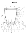
- an inner surface of the vessel wall 14 is provided with a non-stick coating 17, both in the respective overall representation as well as in the zoom-out according to Fig. 2 is shown for clarity in an exaggerated thickness.
- the non-stick coating 17 preferably has a thickness of 0.5 to 3 ⁇ m.
- the non-stick coating 17 is preferably a ceramic non-stick coating.
- the non-stick coating is preferably achieved by applying a ceramic gel to the inner surface of the mixing vessel 7 and subsequent heat treatment.
- the heat treatment can be carried out, for example, in the temperature range of 400 ° C.
- the non-stick coating 17 preferably extends over the entire vertical height h 2 of the interior 16 of the mixing vessel 7, starting from an upper opening edge 15 of the mixing vessel 7 to the transition of the vessel wall 14 in a Rntongefäßêt 10.
- the non-stick coating 17 is complete, the means gapless, the inside wall of the vessel wall 14 is provided.
- the mixing vessel bottom 10 may also be provided with the non-stick coating 17 on the surface facing the interior 16. It may be a homogeneous, uniform material transition of the non-stick coating of the Rhakgefäßêt 10 to the inside of the vessel wall 14 may be formed.
- FIG. 3 shows in one embodiment, a non-stick coating 17, which extends directly from the opening edge 15, starting vertically downwards in the direction of the agitator 8 and on the Rhakgefäßêt 10 over a vertical height h 1 .
- the height h 1 preferably comprises a larger part of the height h 2 .
- a vertically lower boundary 19 of the non-stick coating 17 with a vertical dimension to the Rhakgefäßêt 10 is spaced.
- This vertical dimension may preferably be defined as the distance between a horizontal plane H defined by one or the vertically uppermost stirring arms 9 up to the transition into the mixing vessel bottom 10.
- the horizontal plane H can be defined in its vertical arrangement in further detail in that it extends in contact with a vertically uppermost region of a stirring arm (based on all existing stirring arms). It can also be defined in its vertical arrangement in that it extends in contact with a vertically uppermost region of a stirring arm (based on all existing stirring arms) at its radially outermost end.
- the vertical arrangement may also be defined by being placed between one of the two positions described above. In this case, any intermediate position can be assumed, in particular in 1/10 steps of the defined uppermost and lowermost arrangement of the vertical plane or in a related area.
- the non-stick coating 17 extends uninterruptedly over the entire circumference of the vessel inner wall. This possibly limited to the already specified height extent (vertical dimension).
- Fig. 4 an embodiment is shown, in which the non-stick coating 17, starting from the opening edge 15 extends vertically down to the directly associated with the agitator 8 vessel wall portion 18.
- the vertically lower limit of the non-stick coating 17 relative to the first embodiment is minimally upwardly spaced from the horizontal plane H defined by the uppermost stirring arms 9.
- the minimum spacing can be one quarter to one hundredth of the total vertical dimension of the non-stick coating 17 from the opening edge to the first Vessel wall section 18 amount.
- the non-stick coating 17 preferably extends over a height h 1 which corresponds to approximately nine tenths of the total height h 2 of the mixing vessel interior 16.
- the non-stick coating 17 extends vertically upwards as in the embodiment according to FIG Fig. 5
- a vertical upper boundary 20 is preferably spaced apart from the opening edge 15, this more preferably with a vertical distance h 3 , which corresponds to about one tenth of the total height h 2 of the mixing vessel interior 16.
- a vertical extension h 4 of the non-stick coating 7 over preferably eight tenths of the total height h 2 of the mixing vessel interior 16 results in an arrangement of the vertically lower boundary 19 of the non-stick coating 17 according to the embodiment Fig. 4 in vertically small distance to the horizontal plane H.
- the possibly uncoated vessel wall section 18 in the region of the agitator 8, and more preferably the optionally uncoated stirred vessel 10 may advantageously have a positive effect in particular a dough, since the non-coating thereby subsets or kneading such a dough in the impact area the agitator 8 is further supported.
- the stirring arms 9 themselves and / or a stirring hub 21 may also be wholly or partially provided with a non-stick coating, preferably in a configuration as described above. If appropriate, only the agitator arms 9 and / or the agitator hub 21st ⁇ B> LIST OF REFERENCES: ⁇ / b> 1 food processor 21 Rhaktechniknabe 2 Control panel 3 regulator 4 button 5 display 6 Rhakgefäßdetermining 7 mixing vessel 8th agitator 9 agitator 10 mixing-vessel 11 heater 12 Power cord 13 cover 14 Vascular wall 15 opening edge 16 inner space 17 Non-stick coating 18 Vascular wall section 19 lower limit 20 upper limit h 1 height h 2 height h 3 Pitch h 4 height x vertical axis H WL
Landscapes
- Engineering & Computer Science (AREA)
- Food Science & Technology (AREA)
- Mechanical Engineering (AREA)
- Mixers Of The Rotary Stirring Type (AREA)
- Food-Manufacturing Devices (AREA)
- Cookers (AREA)
Abstract
Description
- Die Erfindung betrifft zunächst eine Küchenmaschine mit einem Rührgefäß und einem Antrieb für ein Rührwerk in dem Rührgefäß, wobei das Rührgefäß vorzugsweise aufheizbar ist.
- Küchenmaschinen, insbesondere der genannten Art, sind bereits in verschiedener Hinsicht bekannt geworden. Beispielsweise ist auf die
DE 102 10 442 A1 zu verweisen. - Derartige Küchenmaschinen, wie auch die erfindungsgemäße Küchenmaschine, dienen zur Anwendung im Haushaltsbereich. Es handelt sich um insbesondere elektrisch angetriebene Küchenmaschinen.
- Eine solche Küchenmaschine weist eine Aufnahme oder sonstige Halterung für ein Rührgefäß auf. Das Rührgefäß kann in die Aufnahme einsetzbar sein. Das Rührgefäß kann weiter insbesondere bodenseitig ein Rührwerk aufweisen, das mit einem in der Küchenmaschine vorgesehenen Elektroantrieb kuppelbar ist. Die Kupplung ist bevorzugt eine mechanische Kupplung.
- Derartige Küchenmaschinen dienen unter Nutzung des Rührwerkes insbesondere dem Verrühren und/oder Zerkleinern von Gargut in dem Rührgefäß, wobei weiter bevorzugt das Rührgefäß bzw. das darin aufgenommene Gargut aufheizbar ist. Die Aufheizbarkeit des Rührgefäßes und/ oder des Gargutes kann unmittelbar, beispielsweise unter Ausgestaltung des Rührgefäßbodens als elektrische Heizscheibe oder durch Strahlungseinwirkung auf das Gargut erfolgen. Die Aufheizung des Rührgefäßes kann auch mittelbar, beispielsweise induktiv erfolgen. Es kann auch eine Kontaktheizung vorgesehen sein, bei welcher ein Heizelement in wärmeleitendem Kontakt zu einem Bereich des Rührgefäßes, insbesondere einem Rührgefäßboden, ist und die Wärme so durch Kontakt in das Rührgefäß eingebracht wird. Ein Rührgefäßboden und/oder ein Teil der Rührgefäßwandung oder das gesamte Rührgefäß können aufheizbar sein.
- Die Aufheizung ermöglicht es, in dem Rührgefäß auf Zubereitungsgut (Speisen, Gargut) nicht nur mechanisch einzuwirken, sondern auch im Sinne eines Garens. Hierbei kann bevorzugt das Zubereitungsgut (Gargut) kontinuierlich oder diskontinuierlich mittels des Rührwerks bewegt werden.
- Die genannten Merkmale können einzeln oder kombiniert auch im Rahmen der Erfindung von Bedeutung sein.
- Es ist nun mitunter zu beobachten, dass Zubereitungsgut nicht in der erwünschten Weise durch das Rührwerk erfasst wird oder nicht in der erwünschten Weise durch die Heizung erhitzt wird, da es nicht - wiederholt - mit den entsprechenden Bereichen des Rührgefäßes in Kontakt kommt. Vielmehr ist zu beobachten, dass das Zubereitungsgut an der Wandung des Rührgefäßes außerhalb gewünschter Bereiche anhaftet und nicht in der gewünschten Weise wiederholt mechanisch oder im Hinblick auf eine Erwärmung beaufschlagt wird.
- Ausgehend von dem dargelegten Stand der Technik beschäftigt sich die Erfindung mit der Aufgabenstellung, eine Küchenmaschine mit einem Rührgefäß anzugeben, bei welcher das Rührgefäß im Hinblick auf eine mechanische und/oder wärmemäßige Einwirkung auf das Zubereitungsgut vorteilhaft ausgestaltet ist.
- Eine mögliche Lösung der Aufgabe ist nach einem ersten Erfindungsgedanken bei einer Küchenmaschine gegeben, bei welcher darauf abgestellt ist, dass die Innenfläche des Rührgefäßes mit einer Antihaftbeschichtung versehen ist. Zubereitungsgut wie Gar- oder Schneidgut kann hierdurch in wesentlich geringerem Ausmaß nur, wenn überhaupt, in eine dauerhafte Anhaftung an einer Rührgefäßwandung gelangen. Die Einwirkungsmöglichkeit auf das Zubereitungsgut ist verbessert.
- Durch eine Antihaftbeschichtung der Gefäß-Innenfläche lässt sich insbesondere auf das in dem Rührgefäß befindliche und durch das Rührwerk bewegte oder auch zerkleinerte, gegebenenfalls gemahlene, Zubereitungsgut, insbesondere Gar- beziehungsweise Schneidgut, günstiger einwirken. Das Zubereitungsgut, das zufolge des rotierenden Rührwerkes zumindest teilweise gegen die Gefäß-Innenfläche geschleudert wird, rutscht an dieser zufolge der Antihaftbeschichtung wieder ab, im Wesentlichen nach vertikal unten, zumindest tendenziell in Richtung auf den Rührgefäßboden. Somit gelangt das Zubereitungsgut wieder in den Eingriffsbereich des Rührwerkes und/oder eines Heizbereiches in einem unteren Bereich des Rührgefäßes.
- Einem Anhaften von Zubereitungsgut, insbesondere von Gar- und/oder Schneidgut kann durch die Antihaftbeschichtung zumindest an besonders kritischen Bereichen der Gefäß-Innenfläche entgegengewirkt werden.
- Unabhängig hiervon bzw. ergänzend trägt eine solche Antihaftbeschichtung auch dazu bei, dass sich in einfacher Weise das Rührgefäß nach Beendigung einer Zubereitung entleeren lässt. Es muss nicht oder nicht mehr in so wesentlichem Ausmaß anhaftendes Zubereitungsgut von der Innenfläche des Rührgefäßes gegebenenfalls abgekratzt werden.
- Nicht zuletzt erleichtert eine derartige Antihaftbeschichtung auch die Reinigung des Rührgefäßes.
- Die Antihaftbeschichtung kann in einer ersten Ausgestaltung auf der Gefäß-Innenfläche ausgebildet sein, die durch die nach innen weisenden Fläche der Rührgefäßwandung gegeben sein. Also von einem Rührgefäßboden aus gesehen, beginnend an oder oberhalb des Rührgefäßbodens. Vertikal oben kann die Antihaftbeschichtung an einem umlaufenden Öffnungsrand, der auch als Öffnungsrand zu bezeichnen ist, des Rührgefäßes, beginnen bzw. bei Betrachtung von unten abschließen.
- Der Rührgefäßboden, der bevorzugt beheizbar ist, kann gleichfalls ergänzend oder alternativ eine dem Inneren des Rührgefäßes zugewandte Antihaftbeschichtung aufweisen. Insbesondere in einem solchen Fall kann also die Antihaftbeschichtung betreffend die Innenfläche des Rührgefäßes unterbrechungsfrei und vollständig ausgebildet sein.
- In dem Rührgefäßboden kann eine, insbesondere mittig ausgebildete, Durchgreiföffnung vorgesehen sein. Durch die Durchgreiföffnung kann ein die Antriebswelle des Rührwerkes bzw. der Rührwerkmesser aufnehmender Festlegungskörper des Rührwerks greifen.
- Die Antihaftbeschichtung kann im Hinblick auf die Durchgreiföffnung bevorzugt ausgehend vom Übergang des Rührgefäßbodens in die Rührgefäßwandung, nach radial innen bis an einen Öffnungsrand der Durchgreiföffnung ausgebildet sein.
- Alternativ kann auch vorgesehen sein, dass die Antihaftbeschichtung umlaufend oder zumindest teilweise nicht bis nach radial innen an den Öffnungsrand reichend ausgebildet ist. Insbesondere kann ein nicht mit Antihaftbeschichtung versehener, im Grundriss bevorzugt kreisringförmiger, Bereich umgebend zu der Durchgreiföffnung belassen sein. Eine solche Ausgestaltung kann vorteilhaft im Hinblick auf eine zwischen dem Festlegungskörper und dem Rührgefäßboden gegebenenfalls vorgesehene Dichtung sein. Somit kann der Dichtung ein Flächenbereich zugeordnet sein, der gerade nicht mit der Antihaftbeschichtung versehen ist.
- Die Antihaftbeschichtung ist bevorzugt eine auf einer Polymer-Keramik-Nano-Verbindung basierende Beschichtung oder alternativ eine PTFE(Polytetrafluorethylen)-Beschichtung, weiter alternativ eine Silizium-Oxidbeschichtung. Als vorteilhaft erweisen sich weiter Beschichtungen, die unter der Bezeichnung DLC (diamond-like Carbon) bekannt sind.
- Bevorzugt ist die gesamte Antihaftbeschichtung hinsichtlich des hierfür verwendeten Werkstoffs einheitlich gestaltet. Dies bezieht sich insbesondere auf die Antihaftbeschichtung, die auf der nach innen weisenden Fläche der Rührgefäßwandung aufgebracht ist. Darüber hinaus weiter bevorzugt aber auch auf die Antihaftbeschichtung, die auf der nach innen weisenden Fläche des Rührgefäßbodens aufgebracht ist, wenn diese auch ganz oder teilweise mit einer Antihaftbeschichtung versehen ist.
- Insbesondere ist bevorzugt, dass die Antihaftbeschichtung einheitlich, das heißt ohne Ausnahme, aus einer PTFE-freien keramischen Antihaftbeschichtung besteht. Bevorzugt auch einheitlich mit einer übereinstimmenden Form der Oberflächengestaltung.
- Alternativ kann aber auch vorgesehen sein, dass einen oder mehrere Bereiche, gegebenenfalls im Umfangsrichtung des Rührgefäßes gesehen und/oder in vertikaler Richtung des Rührgefäßes gesehen, mit unterschiedlichen Formen der Oberflächengestaltung und/oder Materialien als Antihaftbeschichtung versehen sind. Hierbei kann es sich um zueinander beanstandete Bereiche handeln. In einer einfachen Ausgestaltung kann es sich um streifenförmige Bereiche handeln. Die streifenförmigen Bereiche können vertikal orientiert sein oder horizontal orientiert sein.
- Bezüglich der nach innen weisenden Fläche der Rührgefäßwandung kann eine erste Art der Antihaftbeschichtung vorgesehen sein und auf dem Rührgefäßboden eine zweite Art der Antihaftbeschichtung. Die Antihaftbeschichtung der nach innen weisenden Fläche der Rührgefäßwandung kann also materialmäßig eine andere Antihaftbeschichtung sein als diejenige im Bereich des Rührgefäßbodens.
- Eine bevorzugt vorgesehene PTFE-freie keramische Antihaftbeschichtung kann so ausgebildet sein, dass sie bis 450°C oder höher, beispielsweise bis hin zu 500°C oder 600°C, erhitzt werden kann, ohne dass die Beschichtung Schaden nimmt. Selbst im Falle einer Überhitzung werden keine schädlichen Dämpfe freigesetzt, dies bedingt durch die bevorzugte umweltverträgliche Zusammensetzung auf keramischer Basis ohne Polytetrafluoräthylen (PTFE) und weiter bevorzugt ohne Perfluoroctansäure (PFOA).
- Eine Antihaftbeschichtung kann im täglichen Gebrauch hinsichtlich Energieeffizienz vorteilhaft sein. Eine Antihaftbeschichtung der hier beschriebenen Ausgestaltung zeichnet sich bevorzugt durch eine hohe Wärmedurchlässigkeit aus. Sie trägt zu einer guten Verteilung der Wärme bei.
- Darüber hinaus liegt die Kratzfestigkeit einer solchen keramischen Antihaftbeschichtung um ein Vielfaches über der herkömmlicher Beschichtungen. Eine Keramik-Antihaftbeschichtung basiert bevorzugt auf Silizium-Dioxid.
- Eine Schichtdicke der Antihaftbeschichtung, grundsätzlich unabhängig von ihrer tatsächlichen materialmäßigen Ausgestaltung, ist bevorzugt im Mikrometerbereich vorgesehen. Es handelt sich um eine Dünnschicht. Insbesondere ist sie in einer Dicke von 0,5 bis 3 µm vorgesehen.
- Eine bevorzugte Ausgestaltung ist auch dadurch gegeben, dass, gesehen von dem Rührgefäßboden aus, die Antihaftbeschichtung erst oberhalb eines Übergangs des Rührgefäßbodens in die Rührgefäßwandung beginnt. Weiter bevorzugt ist die Innenfläche des Rührgefäßes erst oberhalb eines in horizontaler Richtung dem Rührwerk zugeordneten Bereiches der Innenfläche mit einer Antihaftbeschichtung versehen.
- Der sich im Bereich des Rührwerkes, bezogen auf eine vertikale Erstreckung des Rührwerkes, befindliche Gefäß-Wandungsabschnitt, insbesondere der gesamte umlaufende, dem Bereich des Rührwerks zugeordnete Gefäß-Wandungsabschnitt, weist bevorzugt keine Antihaftbeschichtung auf. Somit ergibt sich, dass ein solcher nicht mit Antihaftbeschichtung versehener Bereich der Innenfläche des Rührgefäßes eine größere Rauigkeit aufweist. Dies kann sich bei der Nutzung der Küchenmaschine als Vorteil erweisen. Beispielsweise bei einer Zubereitung von Teig oder sonstigem Zubereitungsgut, da das Zubereitungsgut, insbesondere der Teig, im Bereich des Rührwerks, gefäßwandungsseitig auf einen, wenn auch geringen, Widerstand trifft, was die Untermengung, insbesondere bei der Teigherstellung, in vorteilhafter Weise unterstützt. Unabhängig von der Freiheit von einer Antihaftbeschichtung des genannten, dem Rührwerk zugeordneten Bereich der Rührgefäß-Innenfläche ist ergänzend oder alternativ auch der Rührgefäßboden frei von einer Antihaftbeschichtung.
- Bevorzugt ist auch vorgesehen, dass die Antihaftbeschichtung erst beginnend (gesehen vom Rührgefäßboden) oberhalb eines horizontalen Projektionsbereiches eines oder mehrerer der Rührarme des Rührwerks vorgesehen ist. Hierbei kann weiter bevorzugt die Antihaftbeschichtung, gesehen von einem Rührgefäßboden nach oben zum Rührgefäßrand, erst oberhalb einer durch den oder die vertikal obersten Arme des Rührwerks definierten, quer zu einer Rührwerksachse sich erstreckenden Horizontalebene beginnend vorgesehen sein. Die Antihaftbeschichtung kann unmittelbar oberhalb einer solchen Horizontalebene beginnend nach oben sich erstrecken, oder, wie weiter bevorzugt, die Antihaftbeschichtung oberhalb einer durch den oder die vertikal obersten Rührarme des Rührwerks definierten, quer zu einer Rührwerksachse sich erstreckenden Horizontalebene beginnend (in Richtung auf den Öffnungsrand gesehen) vorgesehen ist. Die Antihaftbeschichtung kann unmittelbar oberhalb dieser Horizontalebene beginnend sich erstrecken oder, wie weiter bevorzugt, mit einem vertikalen Abstand zu der Horizontalebene von bevorzugt 1 mm bis hin zu 30 mm, weiter bevorzugt 5 bis 10 mm.
- Bevorzugt ist weiter, dass bezogen auf eine vertikale Höhe des Innenraumes des Rührgefäßes ein Zehntel oder mehr der Innenfläche mit einer Antihaftbeschichtung versehen ist, weiter bevorzugt bis hin zu neun Zehntel, bevorzugt bis zu zwei Drittel. So ergibt sich bei einer beispielhaften vertikalen Höhe des Innenraumes des Rührgefäßes von 200 bis 250 mm eine Antihaftbeschichtung, die sich über ein vertikales Erstreckungsmaß von 20 bis 225 mm, weiter bevorzugt über etwa 160 bis 170 mm erstreckt.
- Die Antihaftbeschichtung ist bevorzugt bis zu einem Öffnungsrand, der einem oberen umlaufenden Öffnungsrand des Rührgefäßes entspricht, durchgehend ausgebildet. Bevorzugt ausgehend von einem Bereich oberhalb des dem Rührwerk unmittelbar zugeordneten Bereiches nach vertikal oben bis hin zu dem genannten Öffnungsbereich des Rührgefäßes. Alternativ endet die Antihaftbeschichtung in vertikaler Richtung unterhalb des Öffnungsrandes des Rührgefäßes. Entsprechend ist eine vertikal obere Begrenzungslinie der Antihaftbeschichtung mit vertikalem Abstand zu dem Öffnungsrand des Rührgefäßes positioniert, so weiter bevorzugt mit einem vertikalen Abstand, der einem Zwanzigstel bis einem Drittel, weiter bevorzugt einem Zehntel bis zwei Zehntel der vertikalen Höhe des Innenraumes des Rührgefäßes, entsprechend weiter bevorzugt etwa 10 bis 80 mm, insbesondere 20 bis 50 mm.
- Die bevorzugte Ausgestaltung kann auch dadurch gegeben sein, dass die vertikale Höhe der Antihaftbeschichtung abgetragen von einer dem Öffnungsrand zugewandten oder mit diesem zusammenfallenden oberen Begrenzung der Antihaftbeschichtung in Richtung auf den Boden des Rührgefäßes, über welche bevorzugt keine oder jedenfalls keine flächendeckende Antihaftbeschichtung ausgebildet ist, ein Zehntel oder mehr bis hin zu acht Zehntel der vertikalen Höhe des Innenraumes des Rührgefäßes beträgt.
- Weiter bevorzugt weist die Antihaftbeschichtung eine mikrostrukturierte Oberfläche auf. Die Oberfläche, insbesondere in Form einer Mikrostruktur, kann schuppen- oder riefenartig sein. Sie kann auch wellen- oder punktartig sein. Die Mikrostruktur bezieht sich insbesondere bevorzugt darauf, dass entsprechende Ausformungen, als beispielsweise eine Schuppe, eine größte Dimension in der Fläche (Grundriss) von 50 µm oder weniger aufweisen, bis hin zu beispielsweise 2µm oder 3µm.
- Die Antihaftbeschichtung kann eine Rautiefe von 1 µm oder mehr aufweisen, bevorzugt bis hin zu 1 mm.
- In bevorzugter Ausgestaltung ist die Antihaftwirkung durch eine Oberfläche mit sehr geringer Rautiefe, insbesondere durch eine polierte Oberfläche erreicht. Die Rautiefe kann insofern im Bereich von 0,005 µm bis hin zu 25 µm gegeben sein.
- Die Antihaftbeschichtung kann durch den Auftrag einer Nano-Beschichtung gebildet sein.
- Bevorzugt ist die Antihaftbeschichtung über den Umfang des Gefäßes und/oder die Höhe unterbrochen. Das Fließverhalten insbesondere von Flüssigkeiten ist abhängig von der inneren Reibung (Viskosität) und den Reibkoeffizienten an den die Flüssigkeit umgebenden Oberflächen. Das Strömungsverhalten ist abhängig von der Schubspannung und der Schergeschwindigkeit des Fluids. In beiden Fällen wird das rotierende Medium (Zubereitungsgut) durch unterschiedliche Oberflächenbeschaffenheiten unterschiedlich stark (negativ) beschleunigt, d.h. abgebremst, so dass die Durchmischung an der Behälterwand (Verwirbelungen durch Schubspannung) und damit im ganzen Zubereitungsgut erhöht wird.
- Die unterschiedlichen Oberflächenbeschaffenheiten sind bevorzugt erreicht durch antihaftbeschichtete Zonen, die von nicht antihaftbeschichteten Zonen unterbrochen sind. Alternativ oder kombinativ wird bevorzugt, dass Antihaftzonen unterschiedlicher Rautiefen vorgesehen sind.
- Die Erfindung betrifft weiter ein Verfahren zur Herstellung eines Rührgefäßes für eine Küchenmaschine, insbesondere eines aufheizbares Rührgefäßes.
- Derartige Rührgefäße werden bevorzugt aus einem Metallwerkstoff, beispielsweise Edelstahl, etwa einem Edelstahlblech, hergestellt. Die Herstellung kann durch Tiefziehen im Tiefziehverfahren erfolgen.
- Im Hinblick auf die eingangs herausgestellten sich mitunter ergebenden Nachteile des Anhaftens von Zubereitungsgut an einer Innenfläche des Rührgefäßes beschäftigt sich die Erfindung im Hinblick auf das Verfahren mit der Aufgabenstellung, ein Verfahren zur Herstellung des Rührgefäßes anzugeben, das eine günstige Wechselwirkung zu dem Zubereitungsgut ermöglicht.
- Eine mögliche Lösung der Aufgabe ist nach einem weiteren Erfindungsgedanken bei einem Verfahren gegeben, bei welchem darauf abgestellt ist, dass das metallische Rührgefäß an seiner Innenfläche mit einer Keramikmasse beschichtet wird, die durch Einbrennen an der Innenfläche verhaftet wird. Es wird somit ein Rührgefäß hergestellt, dessen nach innen weisende Fläche ganz oder teilweise durch eine Antihaftbeschichtung gebildet ist.
- Eine Rührwerksnabe und/oder auch die Rührwerksarme oder jedenfalls an den Rührwerksarmen ausgebildete Messer können auch mit einer Antihaftbeschichtung, wie beschrieben, versehen sein.
- Die Aufbringung der Antihaftbeschichtung wird bevorzugt bei ansonsten vollständig fertiggestelltem Rührgefäß vorgenommen. Alternativ kann auch ein gesonderter Rührgefäßboden - zunächst - ausgebildet werden und mit einer Antihaftbeschichtung versehen werden, wie auch die Innenfläche der Rührgefäßwandung und sodann erst die Teile zu dem gesamten Rührgefäß zusammengesetzt werden. Die Zusammensetzung kann auch beispielsweise in einem Verschweißen oder Verkleben der Teile miteinander bestehen.
- Die Antihaftbeschichtung auf Keramikbasis weist eine hohe Festigkeit gegenüber mechanischer Beanspruchung auf. Sie weist darüber hinaus auch eine gute Wärmeleitfähigkeit auf.
- Die Keramikmasse kann im Sol-Gel-Verfahren auf die Innenfläche des Rührgefäßes aufgebracht werden. Hierbei handelt es sich um ein nass-chemisches Verfahren zur Herstellung keramischer oder keramisch-organischer Werkstoffe. Der Übergang vom flüssigen Sol zum keramischen Werkstoff erfolgt über einen Gelzustand, wobei es während der Sol-Gel-Transformation zu einer dreidimensionalen Vernetzung der Partikel im Lösungsmittel kommt, wodurch das Gel Festkörpereigenschaften erhält. Die Überführung des Gels in einen oxidkeramischen Werkstoff erfolgt durch kontrollierte Wärmebehandlung, bevorzugt unter Luft. Der bevorzugt auf die Innenfläche, weiter bevorzugt auch auf die nach innen weisende Fläche des Rührgefäßbodens aufgebrachte Gel-Film wird einer Wärmebehandlung unter sauerstoffhaltiger Atmosphäre unterzogen.
- Bevorzugt wird die Keramikmasse durch Aufstreichen auf die Innenfläche oder weiter beispielsweise durch Aufspritzen auf die Innenfläche aufgebracht.
- In einer weiter bevorzugten Ausgestaltung des Verfahrens ist vorgesehen, dass das Einbrennen bei einer Temperatur von ca. 350 bis 450°C, bevorzugt ca. 400°C vorgenommen wird.
- Bezüglich der vor- und nachstehend angegebenen Wertebereiche sind jeweils auch alle Zwischenwerte, insbesondere in ein Zehntel-Schritten der jeweiligen Dimension, also bei Grad in ein Zehntel-Grad, bei Millimeter in ein Zehntel-Millimeter-Schritten etc. hinsichtlich einer ein- oder mehrfachen Einengung der angegebenen Bereichsgrenzen von oben und/oder unten, wie auch zur Offenbarung singulärer Werte innerhalb der angegebenen Bereiche hiermit in die Offenbarung eingeschlossen.
- Eine Küchenmaschine, wie sie hier beschrieben ist, zeichnet sich insbesondere dadurch aus, dass das Rührgefäß eine Höhe von 10 bis 40 cm aufweist (freie Innenhöhe, gemessen von einer Oberseite eines Rührgefäßbodens bis zum Öffnungsrand) und/oder ein Volumen von ½ bis 4 Liter beispielsweise aufweist.
- Nachstehend ist die Erfindung anhand der beigefügten Zeichnung erläutert, die aber lediglich Ausführungsbeispiele darstellt. Ein Teil, das nur bezogen auf eines der Ausführungsbeispiele erläutert ist und bei einem weiteren Ausführungsbeispiel aufgrund der dort herausgestellten Besonderheit nicht (gerade) durch ein anderes Teil ersetzt ist, ist damit auch für dieses weitere Ausführungsbeispiel als jedenfalls mögliches vorhandenes Teil beschrieben. Auf der Zeichnung zeigt:
- Fig. 1
- in einem partiellen Vertikalschnitt eine Küchenmaschine der in Rede stehenden Art mit einem gefäßwandungsinnenseitig mit einer Antihaftbeschichtung versehenen Rührgefäß, eine erste Ausführungsform betreffend;
- Fig. 2
- die Herausvergrößerung des Bereiches II in
Fig. 1 ; - Fig. 3
- eine der
Fig. 1 entsprechende Darstellung, betreffend eine zweite Ausführungsform; - Fig. 4
- eine dritte Ausführungsform gemäß der Darstellung in
Fig. 1 ; und - Fig. 5
- eine vierte Ausführungsform gemäß der Darstellung in
Fig. 1 . - Dargestellt und beschrieben ist zunächst mit Bezug zu
Fig. 1 eine elektrisch betriebene Küchenmaschine 1. Die Küchenmaschine 1 kann ein Bedienfeld 2 aufweisen, bei dem im Weiteren Regler und/oder Taster 3, 4 vorgesehen sein können. Es kann auch ein Display 5 zum Anzeigen der insbesondere über die Regler und/oder Taster 3, 4 einzustellenden Parameter, wie bspw. eine Rührwerk-Drehzahl und/oder eine Heiztemperatur vorgesehen sein. - Des Weiteren kann die Küchenmaschine 1 über eine Rührgefäßaufnahme 6 verfügen. In der Rührgefäßaufnahme 6 kann ein Rührgefäß 7 formschlüssig aufnehmbar und halterbar sein. Die Aufnehmbarkeit und Halterbarkeit kann auf einen Fußbereich des Rührgefäßes 7 beschränkt sein. Das Rührgefäß 7 ist bevorzugt im Wesentlichen rotationssymmetrisch ausgebildet, mit einer zentralen Vertikalachse x.
- Im Bodenbereich weist das Rührgefäß 7 ein Rührwerk 8 auf. Das Rührwerk 8 kann in der Zuordnungsstellung des Rührgefäßes 7, beispielsweise in der Rührgefäßaufnahme 6 befindlich, formschlüssig gekoppelt mit einem in der Küchenmaschine 1 vorgesehenen, nicht dargestellten, elektromotorischen Rührwerksantrieb sein.
- Das Rührwerk 8 weist mindestens einen, bevorzugt mehrere Rührarme 9 auf, weiter bevorzugt zwei Rührarm-Paare. Von den Rührwerk-Paaren kann ein Rührwerk-Paar vertikal oberhalb des anderen Rührwerk-Paares angeordnet sein. Die Rührarme 9 eines Rührwerk-Paares erstrecken sich bevorzugt in diametraler Gegenüberlage nach radial außen. Ein Rührarm 9 oder die Rührarme 9 eines Rührwerk-Paares können ausgehend von einer Rührwerkachse zumindest tendenziell und abschnittweise in Richtung auf einen Rührgefäßboden 10 gerichtet sein.
- Eine Rührwerksachse ist in Zuordnungsstellung des Rührgefäßes 7 zur Küchenmaschine 1 bevorzugt vertikal verlaufend ausgerichtet. Weiter bevorzugt fällt die Rührwerkachse 7 in dieser Zuordnungsstellung mit einer Vertikalachse x des Rührgefäßes 7 zusammen.
- Die Elektroversorgung des Rührwerkantriebes sowie einer weiter bevorzugt behälterbodenseitig vorgesehenen Heizung 11, bspw. in Form einer elektrischen Widerstandsheizung, und darüber hinaus auch die elektrische Steuerung der gesamten Küchenmaschine 1 ist über ein Netzanschlusskabel 12 erreicht.
- Das Rührgefäß 7 ist weiter insbesondere im Betrieb des Rührwerks 8 bevorzugt durch einen Deckel 13 verschlossen.
- Das Rührgefäß 7 weist weiter bevorzugt eine aus einem Metallwerkstoff bestehende Gefäß-Wandung 14 auf, weiter bevorzugt eine Edelstahlwandung. Ein vertikal oberes Ende der Gefäß-Wandung 14 bildet einen insbesondere durch Abnahme des Deckels 13 freizulegenden Öffnungsrand 15.
- Einem Innenraum 16 des Rührgefäßes 7 zugewandt ist eine Innenfläche der Gefäß-Wandung 14 mit einer Antihaftbeschichtung 17 versehen, die sowohl in der jeweiligen Gesamtdarstellung als auch in der Herausvergrößerung gemäß
Fig. 2 zur Verdeutlichung in einer übertrieben starken Dicke dargestellt ist. Die Antihaftbeschichtung 17 weist bevorzugt eine Dicke von 0,5 bis 3 µm auf. - Die Antihaftbeschichtung 17 ist bevorzugt eine keramische Antihaftbeschichtung. Die Antihaftbeschichtung ist bevorzugt durch Auftragen eines keramischen Gels auf die Innenfläche des Rührgefäßes 7 und anschließender Hitzebehandlung erreicht. Die Hitzebehandlung kann beispielsweise im Temperaturbereich von 400°C vorgenommen sein.
- Die Antihaftbeschichtung 17 erstreckt sich bevorzugt über die gesamte vertikale Höhe h2 des Innenraumes 16 des Rührgefäßes 7, entsprechend ausgehend von einem oberen Öffnungsrand 15 des Rührgefäßes 7 bis hin zum Übergang der Gefäßwandung 14 in einen Rührgefäßboden 10. Bevorzugt ist die Antihaftbeschichtung 17 vollständig, das heißt lückenlos, wandungsinnenseitig der Gefäß-Wandung 14 vorgesehen.
- Darüber hinaus kann auch der Rührgefäßboden 10 auf der dem Innenraum 16 zugewandten Oberfläche mit der Antihaftbeschichtung 17 versehen sein. Es kann ein homogener, materialeinheitlicher Übergang der Antihaftbeschichtung von dem Rührgefäßboden 10 zur Innenseite der Gefäßwandung 14 ausgebildet sein.
- In den weiter nachstehend beschriebenen Ausführungsformen gemäß den
Figuren 3 bis 5 erstreckt sich die Antihaftbeschichtung 17 ausgehend von einem vertikalen, sich im Bereich des Rührwerks 8 befindlichen Gefäß-Wandungsabschnittes 18 aus nach oben. Entsprechend ist der dem Rührgefäßboden 10 zugewandte Gefäß-Wandungsabschnitt 18 nicht mit einer Antihaftbeschichtung 17 versehen. - Die
Figur 3 zeigt in einer Ausführungsform eine Antihaftbeschichtung 17, welche unmittelbar vom Öffnungsrand 15 ausgehend sich nach vertikal unten in Richtung auf das Rührwerk 8 bzw. auf den Rührgefäßboden 10 über eine vertikale Höhe h1 erstreckt. Die Höhe h1 umfasst bevorzugt einen größeren Teil der Höhe h2. Beispielsweise zwei Drittel der gesamten Höhe h2 des Innenraumes 16 des Rührgefäßes 7. Hieraus folgend ist eine vertikal untere Begrenzung 19 der Antihaftbeschichtung 17 mit einem vertikalen Maß zum Rührgefäßboden 10 beabstandet. Dieses vertikale Maß kann bevorzugt dem Abstands zwischen einer von einem oder den vertikal obersten Rührarmen 9 definierten Horizontalebene H ausgehend bis zu dem Übergang in den Rührgefäßboden 10 definiert sein. - Die Horizontalebene H kann in ihrer Vertikalanordnung in weiterer Einzelheit dadurch definiert sein, dass sie berührend zu einem vertikal obersten Bereich eines Rührarmes (bezogen auf alle vorhandenen Rührarme) verläuft. Sie kann in ihrer Vertikalanordnung auch dadurch definiert sein, dass sie berührend zu einem vertikal obersten Bereich eines Rührarmes (bezogen auf alle vorhandenen Rührarme) an dessen radial äußerstem Ende verläuft. Darüber hinaus kann die Vertikalanordnung auch dadurch definiert sein, dass sie zwischen einer der beiden vorstehend beschriebenen Positionen gegeben ist. Hierbei kann jede Zwischenposition eingenommen werden, insbesondere in 1/10-Schritten der definierten obersten und untersten Anordnung der Vertikalebene oder in einem diesbezüglichen Bereich. So kann beispielsweise vorgesehen sein, dass die genannte Horizontalebene H 2/10 des Abstandes zwischen einer Stellung berührend zu einem vertikal obersten Bereich eines Rührarmes und berührend zu einem vertikal obersten Bereich eines Rührarmes an dessen radial äußerstem Ende, abgetragen von dem obersten Wert nach unten und/oder dem untersten Wert nach oben, verläuft. Oder in einem diesbezüglichen vertikalen Bereich verläuft.
- Bevorzugt erstreckt sich die Antihaftbeschichtung 17 ununterbrochen über den gesamten Umfang der Gefäß-Innenwandung. Dies gegebenenfalls begrenzt auf die schon angegebene Höhenerstreckung (Vertikalmaß).
- In
Fig. 4 ist eine Ausführungsform dargestellt, bei welcher sich die Antihaftbeschichtung 17 ausgehend von dem Öffnungsrand 15 nach vertikal unten bis zu dem unmittelbar dem Rührwerk 8 zugeordneten Gefäß-Wandungsabschnitt 18 erstreckt. Im Hinblick auf die Definition des Gefäß-Wandungsabschnittes 18 ausgehend von einer durch einen vertikal obersten Rührarm gegebenen Horizontalebene H oder ausgehend von einer Zwischenstellung oder untersten Stellung wie vorstehend beschrieben kann noch ein gewisser zusätzlicher Freiraum diesbezüglich gegeben sein. Dementsprechend ist die vertikal untere Begrenzung der Antihaftbeschichtung 17 gegenüber der ersten Ausführungsform nach oben minimal beabstandet zu der durch die obersten Rührarme 9 definierten Horizontalebene H. Die minimale Beabstandung kann ein Viertel bis ein Hunderstel des vertikalen Gesamtmaßes der Antihaftbeschichtung 17 ausgehend von dem Öffnungsrand bis zu dem Gefäß-Wandungsabschnitt 18 betragen. Die Antihaftbeschichtung 17 erstreckt sich entsprechend bevorzugt über eine Höhe h1, welche etwa neun Zehntel der Gesamthöhe h2 des Rührgefäß-Innenraumes 16 entspricht. - Weiter alternativ erstreckt sich die Antihaftbeschichtung 17 nach vertikal oben, wie in der Ausführungsform gemäß
Fig. 5 dargestellt, nicht bis an den Öffnungsrand 15. Eine vertikal obere Begrenzung 20 ist bevorzugt zu dem Öffnungsrand 15 beabstandet, dies weiter bevorzugt mit einem vertikalen Abstandsmaß h3, welches etwa ein Zehntel der Gesamthöhe h2 des Rührgefäß-Innenraumes 16 entspricht. Bei gleicher Auslegung des Rührgefäßes 7 entsprechend dem Ausführungsbeispiel inFig. 4 und einer vertikalen Erstreckung h4 der Antihaftbeschichtung 7 über bevorzugt acht Zehntel der Gesamthöhe h2 des Rührgefäß-Innenraumes 16 ergibt sich eine Anordnung der vertikal unteren Begrenzung 19 der Antihaftbeschichtung 17 entsprechend dem Ausführungsbeispiel gemäßFig. 4 in vertikal geringer Beabstandung zur Horizontalebene H. - Durch die vollständige oder auch partielle Antihaftbeschichtung der Gefäß-Wandungsinnenseite wird erreicht, dass herumgeschleuderte, anhaftende Gar- oder Zerkleinerungsgüter an der beschichteten Gefäß-Wandung 14 herunterrutschen und damit wieder in den Wirkbereich des Rührwerks 8 gelangen. Durch die Beschichtung ist die Anhaftung auf der Oberfläche verringert. Die Durchmischung des Gargutes wird verbessert und auch die Zerkleinerungsleistung von Zerkleinerungsgütern verbessert, da die Güter schneller zurück in den Wirkbereich des Rührwerkes 8 gelangen. Prozessschritte der Küchenmaschine können hierdurch auch schneller ablaufen als es ohne die Antihaftbeschichtung möglich wäre. Dies bei effektiver Nutzung der Wirkflächen.
- Der gegebenenfalls nicht beschichtete Gefäß-Wandungsabschnitt 18 im Bereich des Rührwerkes 8, sowie weiter bevorzugt der gegebenenfalls nicht beschichtete Rührgefäßboden 10 können sich in vorteilhafter Weise positiv auf insbesondere eine Teigherstellung auswirken, da zufolge der Nichtbeschichtung hierdurch das Untermengen bzw. Verkneten eines solchen Teiges im Einwirkungsbereich des Rührwerks 8 weiter unterstützt wird.
- Die Rührarme 9 selbst und/oder eine Rührwerknabe 21 können auch ganz oder teilweise mit einer Antihaftbeschichtung, bevorzugt in einer Ausgestaltung wie vorstehend beschrieben, versehen sein. Gegebenenfalls auch nur die Rührwerkarme 9 und/oder die Rührwerknabe 21.
Bezugszeichenliste: 1 Küchenmaschine 21 Rührwerknabe 2 Bedienfeld 3 Regler 4 Taste 5 Display 6 Rührgefäßaufnahme 7 Rührgefäß 8 Rührwerk 9 Rührarm 10 Rührgefäßboden 11 Heizung 12 Netzanschlusskabel 13 Deckel 14 Gefäß-Wandung 15 Öffnungsrand 16 Innenraum 17 Antihaftbeschichtung 18 Gefäß-Wandungsabschnitt 19 untere Begrenzung 20 obere Begrenzung h1 Höhe h2 Höhe h3 Abstandsmaß h4 Höhe x Vertikalachse H Horizontalebene
Claims (10)
- Küchenmaschine (1) mit einem Rührgefäß (7) und einem Antrieb für ein Rührwerk (8) in dem Rührgefäß (7), wobei das Rührgefäß (7) vorzugsweise aufheizbar ist, dadurch gekennzeichnet, dass eine Innenfläche des Rührgefäßes (7) mit einer Antihaftbeschichtung (17) versehen ist.
- Küchenmaschine nach Anspruch 1, dadurch gekennzeichnet, dass erst oberhalb eines vertikalen, sich im Bereich des Rührwerks (8) befindlichen Gefäß-Wandungsabschnittes (18) die Innenfläche des Rührgefäßes (7) mit einer Antihaftbeschichtung (17) versehen ist.
- Küchenmaschine nach einem der vorhergehenden Ansprüche, dadurch gekennzeichnet, dass die Antihaftbeschichtung (17) erst oberhalb eines horizontalen Projektionsbereiches des oder der Rührarme (9) vorgesehen ist.
- Küchenmaschine nach einem der vorhergehenden Ansprüche, dadurch gekennzeichnet, dass bezogen auf eine vertikale Höhe (h2) des Innenraumes (16) des Rührgefäßes (7) ein Zehntel oder mehr der Innenfläche mit einer Antihaftbeschichtung (17) versehen ist, und /oder, bevorzugt, dass bezogen auf eine vertikale Höhe (h2) des Innenraumes des Rührgefäßes (7) die Innenfläche bis zu neun Zehntel, bevorzugt zu zwei Drittel, mit einer Antihaftbeschichtung (17) versehen ist.
- Küchenmaschine nach einem der vorhergehenden Ansprüche, dadurch gekennzeichnet, dass die Antihaftbeschichtung (17) bis zu einem Öffnungsrand (15) des Rührgefäßes (7) durchgehend ausgebildet ist.
- Küchenmaschine nach einem der vorhergehenden Ansprüche 1 bis 4, dadurch gekennzeichnet, dass die Antihaftbeschichtung (17) in vertikaler Richtung unterhalb des Öffnungsrandes (15) des Rührgefäßes (7) endet.
- Küchenmaschine nach einem der vorhergehenden Ansprüche, dadurch gekennzeichnet, dass eine vertikale Höhe (h1), abgetragen von einer dem Öffnungsrand (15) zugewandten oberen Begrenzung der Antihaftbeschichtung (17), in Richtung auf den Boden (10) des Rührgefäßes (7), über welche eine Antihaftbeschichtung (17) ausgebildet ist, ein Zehntel oder mehr bis hin zu acht Zehntel der vertikalen Höhe (h2) des Innenraumes des Rührgefäßes (7) beträgt.
- Küchenmaschine nach einem der vorhergehenden Ansprüche, dadurch gekennzeichnet, dass die Antihaftbeschichtung (17) über den inneren Umfang des Rührgefäßes (7) und/oder über die Höhe durch nicht antihaftbeschichtete Bereiche unterbrochen ist.
- Verfahren zur Herstellung eines Rührgefäßes (7) für eine Küchenmaschine (1), insbesondere aufheizbares Rührgefäß (7), dadurch gekennzeichnet, dass das metallische Rührgefäß (7) an seiner Innenfläche mit einer Keramikmasse beschichtet wird, die durch Einbrennen mit der Innenfläche verhaftet wird.
- Verfahren nach Anspruch 9, dadurch gekennzeichnet, dass das Einbrennen bei einer Temperatur von ca. 350 bis 450°C, bevorzugt ca. 400°C vorgenommen wird.
Priority Applications (1)
| Application Number | Priority Date | Filing Date | Title |
|---|---|---|---|
| PL14151863T PL2756785T3 (pl) | 2013-01-22 | 2014-01-21 | Robot kuchenny z misą do mieszania |
Applications Claiming Priority (1)
| Application Number | Priority Date | Filing Date | Title |
|---|---|---|---|
| DE102013100618 | 2013-01-22 |
Publications (2)
| Publication Number | Publication Date |
|---|---|
| EP2756785A1 true EP2756785A1 (de) | 2014-07-23 |
| EP2756785B1 EP2756785B1 (de) | 2018-04-25 |
Family
ID=50000791
Family Applications (1)
| Application Number | Title | Priority Date | Filing Date |
|---|---|---|---|
| EP14151863.9A Active EP2756785B1 (de) | 2013-01-22 | 2014-01-21 | Küchenmaschine mit einem Rührgefäß |
Country Status (6)
| Country | Link |
|---|---|
| EP (1) | EP2756785B1 (de) |
| CN (1) | CN103960995B (de) |
| DE (1) | DE102014100604A1 (de) |
| ES (1) | ES2671975T3 (de) |
| PL (1) | PL2756785T3 (de) |
| PT (1) | PT2756785T (de) |
Cited By (1)
| Publication number | Priority date | Publication date | Assignee | Title |
|---|---|---|---|---|
| FR3051649A1 (fr) * | 2016-05-30 | 2017-12-01 | Hameur | Appareil de preparation culinaire |
Families Citing this family (1)
| Publication number | Priority date | Publication date | Assignee | Title |
|---|---|---|---|---|
| DE102024105612B4 (de) * | 2024-02-28 | 2026-01-22 | Wundermix Gmbh | Einlegeboden zum Einlegen in einen beheizbaren Topf einer Küchenmaschine |
Citations (3)
| Publication number | Priority date | Publication date | Assignee | Title |
|---|---|---|---|---|
| US20020176320A1 (en) * | 2001-04-13 | 2002-11-28 | Sunbeam Products, Inc. A Corporation Of The State Of Delaware | Blender base with food processor capabilities |
| EP1474984A1 (de) * | 2003-05-07 | 2004-11-10 | Samsung Electronics Co., Ltd. | Backblech für Brotbackmaschine und Brotbackmaschine mit demselben |
| US20080257168A1 (en) * | 2007-04-20 | 2008-10-23 | Amy Wolfe | Device for stirring and cooking food |
Family Cites Families (1)
| Publication number | Priority date | Publication date | Assignee | Title |
|---|---|---|---|---|
| DE10210442A1 (de) | 2002-03-09 | 2003-09-18 | Vorwerk Co Interholding | Küchenmaschine |
-
2014
- 2014-01-21 ES ES14151863.9T patent/ES2671975T3/es active Active
- 2014-01-21 EP EP14151863.9A patent/EP2756785B1/de active Active
- 2014-01-21 CN CN201410145751.2A patent/CN103960995B/zh not_active Expired - Fee Related
- 2014-01-21 PT PT141518639T patent/PT2756785T/pt unknown
- 2014-01-21 DE DE201410100604 patent/DE102014100604A1/de not_active Withdrawn
- 2014-01-21 PL PL14151863T patent/PL2756785T3/pl unknown
Patent Citations (3)
| Publication number | Priority date | Publication date | Assignee | Title |
|---|---|---|---|---|
| US20020176320A1 (en) * | 2001-04-13 | 2002-11-28 | Sunbeam Products, Inc. A Corporation Of The State Of Delaware | Blender base with food processor capabilities |
| EP1474984A1 (de) * | 2003-05-07 | 2004-11-10 | Samsung Electronics Co., Ltd. | Backblech für Brotbackmaschine und Brotbackmaschine mit demselben |
| US20080257168A1 (en) * | 2007-04-20 | 2008-10-23 | Amy Wolfe | Device for stirring and cooking food |
Cited By (1)
| Publication number | Priority date | Publication date | Assignee | Title |
|---|---|---|---|---|
| FR3051649A1 (fr) * | 2016-05-30 | 2017-12-01 | Hameur | Appareil de preparation culinaire |
Also Published As
| Publication number | Publication date |
|---|---|
| CN103960995A (zh) | 2014-08-06 |
| DE102014100604A1 (de) | 2014-07-24 |
| EP2756785B1 (de) | 2018-04-25 |
| CN103960995B (zh) | 2019-01-22 |
| PT2756785T (pt) | 2018-06-15 |
| ES2671975T3 (es) | 2018-06-11 |
| PL2756785T3 (pl) | 2018-09-28 |
Similar Documents
| Publication | Publication Date | Title |
|---|---|---|
| DE102011051149B4 (de) | Elektrisch betriebene Küchenmaschine mit einem Gargefäß | |
| EP2529650B1 (de) | Verfahren zur Freigabe eines Deckels eines Zubereitungsgefäßes sowie Küchenmaschine mit einem Gargefäß | |
| EP3099403B1 (de) | Vorrichtung und verfahren zum durchmischen einer masse | |
| EP3513696B1 (de) | Küchenmaschine mit einem abdeckelement für ein zubereitunsgefäss | |
| DE2520909A1 (de) | Ruehrwerk | |
| EP2756785B1 (de) | Küchenmaschine mit einem Rührgefäß | |
| DE102012104639A1 (de) | Küchenmaschine mit einem Rührgefäß | |
| DE102014111216B4 (de) | Abdeckteil zum teilweisen Verschließen einer Durchgangsöffnung eines Gefäßdeckels eines Küchengerätes | |
| CN204969223U (zh) | 一种茶叶炒青装置 | |
| DE102007060749A1 (de) | Küchenmaschine mit einem aufheizbaren Gefäß | |
| DE102015221005A1 (de) | Anlage und Verfahren zum Bereistellen von Dampf sowie Vorrichtung umfassend eine derartige Anlage | |
| EP4101349B1 (de) | Verfahren zum kartoffelschälen und küchenmaschine | |
| DE102007051430B3 (de) | Dissolver | |
| DE202018100265U1 (de) | Zusatzgefäß für ein Zubereitungsgefäß einer Küchenmaschine | |
| DE10335552B4 (de) | Mischwelle zur Durchmischung und Zerteilung von Lebensmittelprodukten sowie Verfahren zur Herstellung eines Überzugs für eine derartige Mischwelle | |
| EP0700262B1 (de) | Arbeitsbehälter für eine elektrisch betriebene haushaltsküchenmaschine | |
| DE202013000166U1 (de) | Gefäß zum Anbraten und Garen von Speisen mit Wendevorrichtung für Gargut | |
| DE10334998A1 (de) | Rührwerk mit beheizbarer Kruke | |
| DE20015128U1 (de) | Kochgeschirr | |
| EP2989947A1 (de) | Abdeckelement für ein verriegelungselement einer küchenmaschine | |
| EP4622513B1 (de) | Flüssigkeitserwärmer | |
| DE202013101532U1 (de) | Mischwerkzeug | |
| WO2025021437A1 (de) | Vorrichtung zur herstellung eines körperpflegemittels, kosmetikums oder eines haushaltsmittels | |
| EP3569372B1 (de) | Verfahren zum beschichten von schneidmessern | |
| DE102015121335A1 (de) | Gargutträger |
Legal Events
| Date | Code | Title | Description |
|---|---|---|---|
| PUAI | Public reference made under article 153(3) epc to a published international application that has entered the european phase |
Free format text: ORIGINAL CODE: 0009012 |
|
| 17P | Request for examination filed |
Effective date: 20140121 |
|
| AK | Designated contracting states |
Kind code of ref document: A1 Designated state(s): AL AT BE BG CH CY CZ DE DK EE ES FI FR GB GR HR HU IE IS IT LI LT LU LV MC MK MT NL NO PL PT RO RS SE SI SK SM TR |
|
| AX | Request for extension of the european patent |
Extension state: BA ME |
|
| R17P | Request for examination filed (corrected) |
Effective date: 20141208 |
|
| RBV | Designated contracting states (corrected) |
Designated state(s): AL AT BE BG CH CY CZ DE DK EE ES FI FR GB GR HR HU IE IS IT LI LT LU LV MC MK MT NL NO PL PT RO RS SE SI SK SM TR |
|
| STAA | Information on the status of an ep patent application or granted ep patent |
Free format text: STATUS: EXAMINATION IS IN PROGRESS |
|
| 17Q | First examination report despatched |
Effective date: 20170714 |
|
| GRAP | Despatch of communication of intention to grant a patent |
Free format text: ORIGINAL CODE: EPIDOSNIGR1 |
|
| STAA | Information on the status of an ep patent application or granted ep patent |
Free format text: STATUS: GRANT OF PATENT IS INTENDED |
|
| INTG | Intention to grant announced |
Effective date: 20171130 |
|
| GRAS | Grant fee paid |
Free format text: ORIGINAL CODE: EPIDOSNIGR3 |
|
| GRAA | (expected) grant |
Free format text: ORIGINAL CODE: 0009210 |
|
| STAA | Information on the status of an ep patent application or granted ep patent |
Free format text: STATUS: THE PATENT HAS BEEN GRANTED |
|
| AK | Designated contracting states |
Kind code of ref document: B1 Designated state(s): AL AT BE BG CH CY CZ DE DK EE ES FI FR GB GR HR HU IE IS IT LI LT LU LV MC MK MT NL NO PL PT RO RS SE SI SK SM TR |
|
| REG | Reference to a national code |
Ref country code: GB Ref legal event code: FG4D Free format text: NOT ENGLISH |
|
| REG | Reference to a national code |
Ref country code: CH Ref legal event code: EP |
|
| REG | Reference to a national code |
Ref country code: AT Ref legal event code: REF Ref document number: 991940 Country of ref document: AT Kind code of ref document: T Effective date: 20180515 |
|
| REG | Reference to a national code |
Ref country code: IE Ref legal event code: FG4D Free format text: LANGUAGE OF EP DOCUMENT: GERMAN |
|
| REG | Reference to a national code |
Ref country code: DE Ref legal event code: R096 Ref document number: 502014008047 Country of ref document: DE |
|
| REG | Reference to a national code |
Ref country code: ES Ref legal event code: FG2A Ref document number: 2671975 Country of ref document: ES Kind code of ref document: T3 Effective date: 20180611 |
|
| REG | Reference to a national code |
Ref country code: PT Ref legal event code: SC4A Ref document number: 2756785 Country of ref document: PT Date of ref document: 20180615 Kind code of ref document: T Free format text: AVAILABILITY OF NATIONAL TRANSLATION Effective date: 20180608 |
|
| REG | Reference to a national code |
Ref country code: NL Ref legal event code: MP Effective date: 20180425 |
|
| REG | Reference to a national code |
Ref country code: LT Ref legal event code: MG4D |
|
| PG25 | Lapsed in a contracting state [announced via postgrant information from national office to epo] |
Ref country code: NL Free format text: LAPSE BECAUSE OF FAILURE TO SUBMIT A TRANSLATION OF THE DESCRIPTION OR TO PAY THE FEE WITHIN THE PRESCRIBED TIME-LIMIT Effective date: 20180425 |
|
| PG25 | Lapsed in a contracting state [announced via postgrant information from national office to epo] |
Ref country code: NO Free format text: LAPSE BECAUSE OF FAILURE TO SUBMIT A TRANSLATION OF THE DESCRIPTION OR TO PAY THE FEE WITHIN THE PRESCRIBED TIME-LIMIT Effective date: 20180725 Ref country code: LT Free format text: LAPSE BECAUSE OF FAILURE TO SUBMIT A TRANSLATION OF THE DESCRIPTION OR TO PAY THE FEE WITHIN THE PRESCRIBED TIME-LIMIT Effective date: 20180425 Ref country code: FI Free format text: LAPSE BECAUSE OF FAILURE TO SUBMIT A TRANSLATION OF THE DESCRIPTION OR TO PAY THE FEE WITHIN THE PRESCRIBED TIME-LIMIT Effective date: 20180425 Ref country code: SE Free format text: LAPSE BECAUSE OF FAILURE TO SUBMIT A TRANSLATION OF THE DESCRIPTION OR TO PAY THE FEE WITHIN THE PRESCRIBED TIME-LIMIT Effective date: 20180425 Ref country code: BG Free format text: LAPSE BECAUSE OF FAILURE TO SUBMIT A TRANSLATION OF THE DESCRIPTION OR TO PAY THE FEE WITHIN THE PRESCRIBED TIME-LIMIT Effective date: 20180725 |
|
| PG25 | Lapsed in a contracting state [announced via postgrant information from national office to epo] |
Ref country code: RS Free format text: LAPSE BECAUSE OF FAILURE TO SUBMIT A TRANSLATION OF THE DESCRIPTION OR TO PAY THE FEE WITHIN THE PRESCRIBED TIME-LIMIT Effective date: 20180425 Ref country code: GR Free format text: LAPSE BECAUSE OF FAILURE TO SUBMIT A TRANSLATION OF THE DESCRIPTION OR TO PAY THE FEE WITHIN THE PRESCRIBED TIME-LIMIT Effective date: 20180726 Ref country code: LV Free format text: LAPSE BECAUSE OF FAILURE TO SUBMIT A TRANSLATION OF THE DESCRIPTION OR TO PAY THE FEE WITHIN THE PRESCRIBED TIME-LIMIT Effective date: 20180425 Ref country code: HR Free format text: LAPSE BECAUSE OF FAILURE TO SUBMIT A TRANSLATION OF THE DESCRIPTION OR TO PAY THE FEE WITHIN THE PRESCRIBED TIME-LIMIT Effective date: 20180425 |
|
| REG | Reference to a national code |
Ref country code: DE Ref legal event code: R097 Ref document number: 502014008047 Country of ref document: DE |
|
| PG25 | Lapsed in a contracting state [announced via postgrant information from national office to epo] |
Ref country code: DK Free format text: LAPSE BECAUSE OF FAILURE TO SUBMIT A TRANSLATION OF THE DESCRIPTION OR TO PAY THE FEE WITHIN THE PRESCRIBED TIME-LIMIT Effective date: 20180425 Ref country code: EE Free format text: LAPSE BECAUSE OF FAILURE TO SUBMIT A TRANSLATION OF THE DESCRIPTION OR TO PAY THE FEE WITHIN THE PRESCRIBED TIME-LIMIT Effective date: 20180425 Ref country code: CZ Free format text: LAPSE BECAUSE OF FAILURE TO SUBMIT A TRANSLATION OF THE DESCRIPTION OR TO PAY THE FEE WITHIN THE PRESCRIBED TIME-LIMIT Effective date: 20180425 Ref country code: RO Free format text: LAPSE BECAUSE OF FAILURE TO SUBMIT A TRANSLATION OF THE DESCRIPTION OR TO PAY THE FEE WITHIN THE PRESCRIBED TIME-LIMIT Effective date: 20180425 Ref country code: SK Free format text: LAPSE BECAUSE OF FAILURE TO SUBMIT A TRANSLATION OF THE DESCRIPTION OR TO PAY THE FEE WITHIN THE PRESCRIBED TIME-LIMIT Effective date: 20180425 |
|
| PG25 | Lapsed in a contracting state [announced via postgrant information from national office to epo] |
Ref country code: SM Free format text: LAPSE BECAUSE OF FAILURE TO SUBMIT A TRANSLATION OF THE DESCRIPTION OR TO PAY THE FEE WITHIN THE PRESCRIBED TIME-LIMIT Effective date: 20180425 |
|
| PLBE | No opposition filed within time limit |
Free format text: ORIGINAL CODE: 0009261 |
|
| STAA | Information on the status of an ep patent application or granted ep patent |
Free format text: STATUS: NO OPPOSITION FILED WITHIN TIME LIMIT |
|
| 26N | No opposition filed |
Effective date: 20190128 |
|
| PG25 | Lapsed in a contracting state [announced via postgrant information from national office to epo] |
Ref country code: SI Free format text: LAPSE BECAUSE OF FAILURE TO SUBMIT A TRANSLATION OF THE DESCRIPTION OR TO PAY THE FEE WITHIN THE PRESCRIBED TIME-LIMIT Effective date: 20180425 |
|
| PG25 | Lapsed in a contracting state [announced via postgrant information from national office to epo] |
Ref country code: MC Free format text: LAPSE BECAUSE OF FAILURE TO SUBMIT A TRANSLATION OF THE DESCRIPTION OR TO PAY THE FEE WITHIN THE PRESCRIBED TIME-LIMIT Effective date: 20180425 |
|
| REG | Reference to a national code |
Ref country code: CH Ref legal event code: PL |
|
| PG25 | Lapsed in a contracting state [announced via postgrant information from national office to epo] |
Ref country code: LU Free format text: LAPSE BECAUSE OF NON-PAYMENT OF DUE FEES Effective date: 20190121 |
|
| REG | Reference to a national code |
Ref country code: BE Ref legal event code: MM Effective date: 20190131 |
|
| REG | Reference to a national code |
Ref country code: IE Ref legal event code: MM4A |
|
| PG25 | Lapsed in a contracting state [announced via postgrant information from national office to epo] |
Ref country code: BE Free format text: LAPSE BECAUSE OF NON-PAYMENT OF DUE FEES Effective date: 20190131 Ref country code: AL Free format text: LAPSE BECAUSE OF FAILURE TO SUBMIT A TRANSLATION OF THE DESCRIPTION OR TO PAY THE FEE WITHIN THE PRESCRIBED TIME-LIMIT Effective date: 20180425 |
|
| PG25 | Lapsed in a contracting state [announced via postgrant information from national office to epo] |
Ref country code: LI Free format text: LAPSE BECAUSE OF NON-PAYMENT OF DUE FEES Effective date: 20190131 Ref country code: CH Free format text: LAPSE BECAUSE OF NON-PAYMENT OF DUE FEES Effective date: 20190131 |
|
| PG25 | Lapsed in a contracting state [announced via postgrant information from national office to epo] |
Ref country code: IE Free format text: LAPSE BECAUSE OF NON-PAYMENT OF DUE FEES Effective date: 20190121 |
|
| REG | Reference to a national code |
Ref country code: AT Ref legal event code: MM01 Ref document number: 991940 Country of ref document: AT Kind code of ref document: T Effective date: 20190121 |
|
| PG25 | Lapsed in a contracting state [announced via postgrant information from national office to epo] |
Ref country code: AT Free format text: LAPSE BECAUSE OF NON-PAYMENT OF DUE FEES Effective date: 20190121 |
|
| PG25 | Lapsed in a contracting state [announced via postgrant information from national office to epo] |
Ref country code: MT Free format text: LAPSE BECAUSE OF FAILURE TO SUBMIT A TRANSLATION OF THE DESCRIPTION OR TO PAY THE FEE WITHIN THE PRESCRIBED TIME-LIMIT Effective date: 20180425 |
|
| PGFP | Annual fee paid to national office [announced via postgrant information from national office to epo] |
Ref country code: TR Payment date: 20200116 Year of fee payment: 7 |
|
| PG25 | Lapsed in a contracting state [announced via postgrant information from national office to epo] |
Ref country code: CY Free format text: LAPSE BECAUSE OF FAILURE TO SUBMIT A TRANSLATION OF THE DESCRIPTION OR TO PAY THE FEE WITHIN THE PRESCRIBED TIME-LIMIT Effective date: 20180425 |
|
| PG25 | Lapsed in a contracting state [announced via postgrant information from national office to epo] |
Ref country code: IS Free format text: LAPSE BECAUSE OF FAILURE TO SUBMIT A TRANSLATION OF THE DESCRIPTION OR TO PAY THE FEE WITHIN THE PRESCRIBED TIME-LIMIT Effective date: 20180825 |
|
| PG25 | Lapsed in a contracting state [announced via postgrant information from national office to epo] |
Ref country code: HU Free format text: LAPSE BECAUSE OF FAILURE TO SUBMIT A TRANSLATION OF THE DESCRIPTION OR TO PAY THE FEE WITHIN THE PRESCRIBED TIME-LIMIT; INVALID AB INITIO Effective date: 20140121 |
|
| PG25 | Lapsed in a contracting state [announced via postgrant information from national office to epo] |
Ref country code: MK Free format text: LAPSE BECAUSE OF FAILURE TO SUBMIT A TRANSLATION OF THE DESCRIPTION OR TO PAY THE FEE WITHIN THE PRESCRIBED TIME-LIMIT Effective date: 20180425 |
|
| P01 | Opt-out of the competence of the unified patent court (upc) registered |
Effective date: 20230517 |
|
| PGFP | Annual fee paid to national office [announced via postgrant information from national office to epo] |
Ref country code: ES Payment date: 20240216 Year of fee payment: 11 |
|
| PGFP | Annual fee paid to national office [announced via postgrant information from national office to epo] |
Ref country code: DE Payment date: 20240119 Year of fee payment: 11 Ref country code: GB Payment date: 20240124 Year of fee payment: 11 Ref country code: PT Payment date: 20240115 Year of fee payment: 11 |
|
| PGFP | Annual fee paid to national office [announced via postgrant information from national office to epo] |
Ref country code: PL Payment date: 20240111 Year of fee payment: 11 Ref country code: IT Payment date: 20240131 Year of fee payment: 11 Ref country code: FR Payment date: 20240123 Year of fee payment: 11 |
|
| PG25 | Lapsed in a contracting state [announced via postgrant information from national office to epo] |
Ref country code: TR Free format text: LAPSE BECAUSE OF NON-PAYMENT OF DUE FEES Effective date: 20210121 |
|
| REG | Reference to a national code |
Ref country code: DE Ref legal event code: R119 Ref document number: 502014008047 Country of ref document: DE |
|
| GBPC | Gb: european patent ceased through non-payment of renewal fee |
Effective date: 20250121 |
|
| PG25 | Lapsed in a contracting state [announced via postgrant information from national office to epo] |
Ref country code: PT Free format text: LAPSE BECAUSE OF NON-PAYMENT OF DUE FEES Effective date: 20250721 |
|
| PG25 | Lapsed in a contracting state [announced via postgrant information from national office to epo] |
Ref country code: DE Free format text: LAPSE BECAUSE OF NON-PAYMENT OF DUE FEES Effective date: 20250801 |
|
| PG25 | Lapsed in a contracting state [announced via postgrant information from national office to epo] |
Ref country code: GB Free format text: LAPSE BECAUSE OF NON-PAYMENT OF DUE FEES Effective date: 20250121 |
|
| PG25 | Lapsed in a contracting state [announced via postgrant information from national office to epo] |
Ref country code: FR Free format text: LAPSE BECAUSE OF NON-PAYMENT OF DUE FEES Effective date: 20250131 |
|
| PG25 | Lapsed in a contracting state [announced via postgrant information from national office to epo] |
Ref country code: IT Free format text: LAPSE BECAUSE OF NON-PAYMENT OF DUE FEES Effective date: 20250121 |
|
| REG | Reference to a national code |
Ref country code: ES Ref legal event code: FD2A Effective date: 20260227 |
|
| PG25 | Lapsed in a contracting state [announced via postgrant information from national office to epo] |
Ref country code: ES Free format text: LAPSE BECAUSE OF NON-PAYMENT OF DUE FEES Effective date: 20250122 |