EP2756317B1 - Linearity enhancement of capacitive transducers by auto-calibration using on-chip neutralization capacitors and linear actuation - Google Patents
Linearity enhancement of capacitive transducers by auto-calibration using on-chip neutralization capacitors and linear actuation Download PDFInfo
- Publication number
- EP2756317B1 EP2756317B1 EP12772167.8A EP12772167A EP2756317B1 EP 2756317 B1 EP2756317 B1 EP 2756317B1 EP 12772167 A EP12772167 A EP 12772167A EP 2756317 B1 EP2756317 B1 EP 2756317B1
- Authority
- EP
- European Patent Office
- Prior art keywords
- actuation
- capacitance
- output value
- neutralization
- proof mass
- Prior art date
- Legal status (The legal status is an assumption and is not a legal conclusion. Google has not performed a legal analysis and makes no representation as to the accuracy of the status listed.)
- Active
Links
Images


Classifications
-
- G—PHYSICS
- G01—MEASURING; TESTING
- G01P—MEASURING LINEAR OR ANGULAR SPEED, ACCELERATION, DECELERATION, OR SHOCK; INDICATING PRESENCE, ABSENCE, OR DIRECTION, OF MOVEMENT
- G01P21/00—Testing or calibrating of apparatus or devices covered by the preceding groups
-
- G—PHYSICS
- G01—MEASURING; TESTING
- G01L—MEASURING FORCE, STRESS, TORQUE, WORK, MECHANICAL POWER, MECHANICAL EFFICIENCY, OR FLUID PRESSURE
- G01L25/00—Testing or calibrating of apparatus for measuring force, torque, work, mechanical power, or mechanical efficiency
-
- G—PHYSICS
- G01—MEASURING; TESTING
- G01L—MEASURING FORCE, STRESS, TORQUE, WORK, MECHANICAL POWER, MECHANICAL EFFICIENCY, OR FLUID PRESSURE
- G01L27/00—Testing or calibrating of apparatus for measuring fluid pressure
- G01L27/002—Calibrating, i.e. establishing true relation between transducer output value and value to be measured, zeroing, linearising or span error determination
-
- G—PHYSICS
- G01—MEASURING; TESTING
- G01D—MEASURING NOT SPECIALLY ADAPTED FOR A SPECIFIC VARIABLE; ARRANGEMENTS FOR MEASURING TWO OR MORE VARIABLES NOT COVERED IN A SINGLE OTHER SUBCLASS; TARIFF METERING APPARATUS; MEASURING OR TESTING NOT OTHERWISE PROVIDED FOR
- G01D18/00—Testing or calibrating apparatus or arrangements provided for in groups G01D1/00 - G01D15/00
- G01D18/002—Automatic recalibration
- G01D18/006—Intermittent recalibration
Definitions
- the present invention relates to a method for automatically calibrating a capacitive transducer according to the preamble of claim 1 which is known from DE 10 2009 026 496 A1 .
- US 577802 A discloses a capacitive transducer with improved capacitive to voltage converter integrated circuit.
- US 5347865 A discloses an accelerometer implementing a capacitive transducer including circuitry for reducing the effective loading capacitance on a movable vane.
- US 2011/042404 A1 discloses a high sensitivity capacitive microaccelerometer having a stiff sense/feedback electrodes and a method of its manufacture on a single-side of a semiconductor wafer.
- Transducers convert a general physical quantity (for example, acceleration, pressure, etc.) to quantities that can be processed by electronic circuits.
- capacitive transducers produce a change of capacitance, corresponding to the magnitude of the measured input signal.
- Readout circuits for capacitive transducers transform the capacitance change produced by the transducer to an electrical signal. In the process, the circuits apply voltage waveforms to the transducer electrodes.
- a capacitive accelerometer a capacitive transducer for measuring acceleration
- a capacitive accelerometer can be designed such that displacement of a set of capacitive plates is proportional to acceleration. Then acceleration can be measured using electronics by measuring the difference in the set of capacitors.
- a capacitive accelerometer can include a mechanical sensing element and a readout circuit.
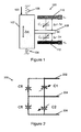
- Figure 1 illustrates an exemplary embodiment of a mechanical sensing element 100 for a capacitive accelerometer.
- the mechanical sensing element 100 includes a proof mass 102 suspended between a first spring 104 and a second spring 106, a first electrode 110 and a second electrode 112. A proximal end of the mass 102 is coupled to the first spring 104 and a distal end of the mass 102 is coupled to the second spring 106.
- the first spring 104 has two ends; a first end coupled to the proximal end of the mass 102 and a second end coupled to a substrate.
- the second spring 106 has two ends; a first end coupled to the distal end of the mass 102 and a second end coupled to the substrate.
- a common electrode M is coupled to the mass 102 and moves with the mass 102 relative to the substrate.
- the first and second electrodes 110,112 are stationary relative to the substrate.
- a positive reference voltage V s is applied to the first electrode 110 and the negative reference voltage -V s is applied to the second electrode 112.
- a first variable capacitor C 1 is formed between the first electrode 110 and the common electrode M
- a second variable capacitor C 2 is formed between the second electrode 112 and the common electrode M.
- This movement of the mass 102 increases the distance between the first electrode 110 and the common electrode M to g 0 + ⁇ x, and decreases the distance between the second electrode 112 and the common electrode M to g 0 - ⁇ x, which changes the capacitance of capacitors C 1 and C 2 .
- the readout circuit determines the value of ⁇ x based on the capacitance change in capacitors C 1 and C 2 .
- Accelerometers are often implemented in harsh vibration-ridden environments, for example automotive or industrial environments. In these environments, it is desirable to have accelerometers with good linearity, low drift performance and large full scale range. Self-balanced accelerometers are usually chosen for these applications. In self-balanced accelerometers, the capacitance C is proportional to 1/d, where d is the distance between the capacitive plates; and the measured Output voltage Vo is proportional to (C 1 - C 2 ) / (C 1 + C 2 ).
- Feed-through capacitance is any fixed capacitance between the proof mass and the sense electrodes.
- the feed-through capacitances Cft arise due to parasitics in the sensor element and due to capacitance between the bond wires.
- Figure 2 illustrates the feed-through capacitance in a capacitive core 200, an example of which is shown in Figure 1 .
- the capacitive core 200 includes a first capacitor C1 between a first sense electrode 202 and a proof mass 204, and a second capacitor C2 between a second sense electrode 206 and the proof mass 204.
- the capacitive core 200 also includes unwanted feed-through capacitances Cft between the proof mass 204 and each of the sense electrodes 202, 206. Re-deriving Eq.
- Nonlinearity due to mismatch in sensor cores occurs in fully differential accelerometers which use two sensor cores.
- a differential topology can provide better robustness to electromagnetic signals and other stray disturbances.
- the sensor cores are often two separate elements with the proof masses not connected mechanically. This is often done to save cost since mechanical connection of the proof masses of the two cores with electrical isolation can be expensive in terms of processing. Under this condition the offsets of the sensor cores can be in opposite directions which causes non-linearity because of remnant electrostatic forces as well as the fact that capacitance is inversely proportional to displacement.
- feed-through capacitance is the dominant source of non-linearity.
- the non-linearity due to a core mismatch of 5 pF (+/-5% core mismatch) is 0.016%.
- the non-linearity due to 50 fF (100 times smaller than 5 pF) remnant feed-through capacitance is 0.43%, which is almost 30 times greater than the core mismatch non-linearity.
- Even a 10 fF remnant feed-through capacitance causes a non-linearity of 0.087%.
- a method for automatically calibrating a capacitive transducer to neutralize feed-through capacitance starting from an initial value for a neutralization capacitance is defined in claim 1.
- the method includes applying no electrostatic force to a proof mass of the capacitive transducer and recording a base output value while no electrostatic force is applied; applying an electrostatic force F0 to the proof mass and recording a first change in the output value of the capacitive transducer between the base output value and a first output value when the electrostatic force F0 is applied; applying an electrostatic force n*F0 to the proof mass and recording a second change in the output value of the capacitive transducer between the first output value and a second output value when the electrostatic force n*F0 is applied to the proof mass; increasing, decreasing or maintaining the neutralization capacitance based on the recorded first and second changes in the output value of the capacitive transducer; and repeating the method until a final value for the neutralization capacitance is reached.
- the electrostatic force F0 is a fraction
- the increasing, decreasing or maintaining step can include decreasing the neutralization capacitance when the first change in the output value is greater than the second change in the output value, and increasing the neutralization capacitance when the first change in the output value is less than the second change in the output value.
- the method can include performing a binary search between a minimum neutralization capacitance and a maximum neutralization capacitance. The method can also include comparing the linearity of the final value for the neutralization capacitance to a linearity threshold.
- the electrostatic forces can be applied to the proof mass using a charge control method. Applying an electrostatic force F0 to the proof mass can include actuating the proof mass for a period t, and applying an electrostatic force n*F0 to the proof mass can include actuating the proof mass for a period n*t.
- the capacitive transducer can include first and second variable capacitors, and applying an electrostatic force can include a first actuation phase for resetting the capacitive transducer by removing charge from the first and second variable capacitors, a second actuation phase for applying the electrostatic actuation force to the capacitive transducer where the electrostatic force is a function of the duration of the second actuation phase, a first measurement phase for reading out the output signal of the capacitive transducer due to the electrostatic actuation force the first measurement phase following the second actuation phase, and a second measurement phase for applying no electrostatic actuation force to the first and second variable capacitors.
- first actuation phase then second actuation phase
- first measurement phase then second measurement phase.
- the second variable capacitor of the capacitive transducer can be short circuited during the second actuation phase.
- Capacitance neutralization is a procedure used in differential circuits to cancel unwanted parasitic capacitances by adding neutralization capacitances of opposite polarity using the differential voltages.
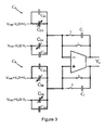
- Figure 3 illustrates an exemplary differential circuit that includes a first capacitive core C A and a second capacitive core C B .
- the first capacitive core C A includes variable capacitors C 1A and C 2A .
- the second capacitive core C B includes variable capacitors C 1B and C 2B .
- Figure 3 also shows the unwanted feed-through capacitances C ft1 , C ft2 , C ft3 , C ft4 that are parallel to the desired sense capacitors C 1A , C 2A , C 1B , C 2B , respectively.
- Figure 4 illustrates the exemplary differential circuit of Figure 3 with on-chip neutralization capacitors added to cancel the unwanted feed-through capacitances.
- the neutralization capacitors C n1 , C n2 , C n3 , C n4 are added in a way to cancel the unwanted feed-through capacitances C ft1 , C ft2 , C ft3 , C ft4 , respectively.
- One method is simply to estimate the mean feed-through capacitance for several parts and put in a nominal neutralization capacitance to cancel the mean feed-through capacitance.
- both the feed-through and neutralization capacitances vary from part to part due to process variation and mismatch which leads to improper cancellation.
- This method can be relatively inexpensive and provides some benefit but is not necessarily accurate for a particular part.
- a more accurate but expensive method to cancel the feed-through capacitance is to put each chip inside a centrifuge. Then as the acceleration is increased using the centrifuge, the output voltage can be read for various on-chip neutralization capacitor settings. The on-chip neutralization capacitance can be set using trim bits. The neutralization capacitance that corresponds to the most linear output measurement versus acceleration curve can then be programmed into the chip. This procedure is expensive in terms of test cost and time since it requires use of a centrifuge and time to load the chips and sweep the measurement versus acceleration curves for each of the chips.
- An alternative method for determining the necessary amount of neutralization capacitance is to measure the linearity of the measured output for two or more precisely known forces.
- a force F0 and twice that force, 2*F0 can be applied to the proof mass and the change in the output can be measured to determine the linearity between the input forces and the output measurements.
- Figure 6 shows three scenarios for this method when the forces F0 and 2*F0 are applied. Other ratios of forces or more forces can be used as long as the relationships between the forces are known.
- the change in output voltage ⁇ V 1 caused by the force F0 equals the change in output voltage ⁇ V 2 caused by the force 2*F0 which produces a linear relationship between displacement and output voltage.
- Figure 6B shows the situation where too much neutralization capacitance is added, C n > C ft .
- the change in output voltage ⁇ V 1 caused by the force F0 is greater than the change in output voltage ⁇ V 2 caused by the force 2*F0 which produces a decreasing non-linear relationship between displacement and output voltage.
- Figure 6C shows the situation where too little neutralization capacitance is added, C n ⁇ C ft .
- the change in output voltage ⁇ V 1 caused by the force F0 is less than the change in output voltage ⁇ V 2 caused by the force 2*F0 which produces an increasing non-linear relationship between displacement and output voltage.
- the non-linearity of the resulting output measurements will indicate whether the neutralization capacitance should be increased or decreased to better model the linearity of the ideal case.
- a force can be applied to the proof mass using electrostatic actuation.
- Figure 7 shows an exemplary automatic calibration procedure 700 for tuning out the feed-through capacitance using on-chip neutralization capacitance, C neut .
- the calibration procedure 700 uses a binary search method between a lower limit for on-chip neutralization capacitance, C min , and an upper limit for on-chip neutralization capacitance, C max .
- Other search schemes known in the art can also be used for finding a value of neutralization capacitance to cancel the feed-through capacitance.
- the system sets the value of neutralization capacitance to be checked, C neut , to the center of the working binary search range (C low + C high )/2.
- no electrostatic actuation is applied to the proof mass and the output value is recorded. This output will include the sensor offset and a fraction of earth's gravitational force depending on the angle of mounting of the proof mass.
- an electrostatic force of F0 is applied to the proof mass and the change in the output value ( ⁇ V1) is recorded.
- an electrostatic force of 2*F0 is applied to the proof mass and the change in the output value ( ⁇ V2) is recorded.
- a force of 2*F0 can be applied by making the duty cycle of actuation twice as long as the duty cycle for the force of F0.
- Other multiples of F0 can also be used to determine linearity.
- the method determines whether the neutralization capacitance should be increased or decreased to better cancel the feed-through capacitance.
- Block 722 is reached because either: (a) the system determined that ⁇ V2 is not less than or greater than ⁇ V1, which leaves that ⁇ V2 equals ⁇ V1; or (b) the binary search is complete. In either case the final value of neutralization capacitance C neut will be used.
- the system can also include a threshold linearity check to ensure that the selected value of neutralization capacitance C neut meets the threshold.
- the threshold check can determine whether the absolute value of the difference between ⁇ V2 and ⁇ V1 is less than the threshold linearity for the final value of neutralization capacitance C neut .
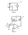
- FIG. 8 shows an exemplary voltage actuation circuit 800.
- a fixed voltage V is applied to sensor capacitor C 1 while sensor capacitor C 2 is shorted.
- FIG. 9 shows an exemplary charge control actuation circuit 900 comprising a sensor core with variable sensor capacitors C 1 and C 2 , an amplifier 902, a capacitor Ca and an input voltage source Va.
- the sensor core is placed in a first feedback path of the amplifier 902, and the sensor capacitor C 2 is shorted so that charge is placed on only the sensor capacitor C 1 of the sensor core.
- the amplifier 902 also includes a second parallel feedback path with a switch that is open during a phase ⁇ A1 . During phase ⁇ A1 , the sensor core is reset and a constant charge Va is gathered on capacitor Ca.
- FIG. 10 shows an exemplary charge control actuation circuit 1000 with the feed-through and neutralization capacitances.
- the feed-through capacitance Cft Cneut
- the charge Q 0 is not only dumped on capacitor C1 but is also dumped on capacitor Cft
- the charge is not linearly split between capacitors C1 and Cft based on the displacement, x.
- FIG. 11 Exemplary timing diagrams for an auto-calibration procedure are shown in Figure 11 .
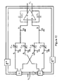
- An exemplary differential capacitive sensor system is shown in Figure 12 .
- time is divided between actuation phases ⁇ A and measurement phases ⁇ M .
- the circuit of Figure 10 is referred to during the actuation phase description, and the circuit of Figure 12 is referred to during the measurement phase description.
- the circuit of Figure 10 is not shown in the circuit of Figure 12 for clarity.
- Figure 12 only shows the circuit during the measurement phase. Including all of the switches in Figure 12 would make Figure 12 extremely complicated.
- Figure 12 shows the sensor and the capacitance-to-voltage circuit during the measurement phase
- Figure 10 shows the sensor and actuation circuits during the actuation phase.
- the actuation phase the sensor is connected as shown in Figure 10 .
- each of the capacitor cores C A and C B are connected as shown in Figure 10 .
- the actuation phase ⁇ A is further divided into two subphases: ⁇ A1 and ⁇ A2 .
- the sensor is disconnected from the front end, so ⁇ 2 equals 0.
- subphase ⁇ A1 the sensor is reset and a constant charge is gathered on capacitor Ca.
- subphase ⁇ A2 the charge is dumped onto the MEMS capacitor C 1 .
- the actuation force is linearly proportional to Tw, the duration or duty cycle of the actuation subphase ⁇ A2 .
- ⁇ A1 is high during the last part of the actuation phase to reset the capacitors to provide zero force and get them ready for the measurement phase.
- the actuation force can be applied to both cores at substantially simultaneously to simulate the application of a force in operation.
- the measurement phase During the measurement phase, the sensor is connected as shown in Figure 12 .
- the measurement phase ⁇ M is divided into two subphases: ⁇ 1 and ⁇ 2 .
- the MEMS capacitors are connected to the front end of the capacitive sensor system and the displacement is read out by the system as a voltage V 0 .
- the voltages are applied to the sensor so that there is no net electrostatic force on the proof masses of the cores C A and C B to cause erroneous actuation.
- Charge control actuation has not previously been reported for linear actuation. Charge-control can be used for linear actuation to obtain immunity to unwanted vibrations that cause the proof mass of the sensor to shake around.
- Continuous self-test is a technique to check that a sensor continues to function properly during operation.
- a background signal force
- This background signal is usually a pseudo-random signal, for example a square wave or a sine wave.
- an output signal caused by this background signal can be read out by the transducer system. If the output signal is within some operational limits of what is expected for the background signal, then it can be assumed that the sensor is working properly. If the output signal is beyond some warning limits, then it can be assumed that the sensor is malfunctioning and it cannot be used to make safety-critical decisions.
- an example of a safety critical decision would be detecting a skid and applying brakes selectively on the wheels according to the sensor signals.
- Linear actuation can be important in a self-test application. For example, in a car there are many vibrations that are several tens of gravitational force (g) that are within the sensor bandwidth.
- An exemplary sensor bandwidth for an accelerometer is usually less than 5 kHz. These multi-g vibrations can cause the proof mass to shake around. If the actuation of the proof mass during self test is non-linear (i.e., the actuation force depends on the proof mass displacement), these vibrations can mix with the actuation signal and change the DC value for the sensor making the subsequent readings inaccurate.
- An example of non-linear actuation is the voltage actuation shown in Eq. (5). The electrostatic force due to voltage actuation is a function of the proof mass displacement squared x 2 , so these vibrations causing the proof mass to shake around during self test can cause inaccurate results.
- Linear actuation can avoid this change to the DC value for the sensor during continuous self-test.
- An example of linear actuation is the charge-control actuation shown in Eq. (7).
- the electrostatic force due to charge-control actuation is not a function of the proof mass displacement x. So vibrations causing the proof mass to shake around during self test do not effect the self-test.
- the self-test can provide accurate results during operation even if there are multi-g vibrations on the sensor.
Landscapes
- Physics & Mathematics (AREA)
- General Physics & Mathematics (AREA)
- Pressure Sensors (AREA)
- Measuring Fluid Pressure (AREA)
- Transmission And Conversion Of Sensor Element Output (AREA)
Applications Claiming Priority (2)
| Application Number | Priority Date | Filing Date | Title |
|---|---|---|---|
| US13/235,334 US9032777B2 (en) | 2011-09-16 | 2011-09-16 | Linearity enhancement of capacitive transducers by auto-calibration using on-chip neutralization capacitors and linear actuation |
| PCT/US2012/055645 WO2013040508A1 (en) | 2011-09-16 | 2012-09-14 | Linearity enhancement of capacitive transducers by auto-calibration using on-chip neutralization capacitors and linear actuation |
Publications (2)
| Publication Number | Publication Date |
|---|---|
| EP2756317A1 EP2756317A1 (en) | 2014-07-23 |
| EP2756317B1 true EP2756317B1 (en) | 2015-09-09 |
Family
ID=47016831
Family Applications (1)
| Application Number | Title | Priority Date | Filing Date |
|---|---|---|---|
| EP12772167.8A Active EP2756317B1 (en) | 2011-09-16 | 2012-09-14 | Linearity enhancement of capacitive transducers by auto-calibration using on-chip neutralization capacitors and linear actuation |
Country Status (5)
| Country | Link |
|---|---|
| US (2) | US9032777B2 (enExample) |
| EP (1) | EP2756317B1 (enExample) |
| JP (1) | JP6088521B2 (enExample) |
| CN (1) | CN103890593B (enExample) |
| WO (1) | WO2013040508A1 (enExample) |
Cited By (2)
| Publication number | Priority date | Publication date | Assignee | Title |
|---|---|---|---|---|
| CN105486450A (zh) * | 2015-12-10 | 2016-04-13 | 中国航空工业集团公司北京长城计量测试技术研究所 | 一种宽量程脉冲力校准装置 |
| CN108195507A (zh) * | 2017-12-16 | 2018-06-22 | 芜湖致通汽车电子有限公司 | 用于传感器自动化批量检测系统 |
Families Citing this family (18)
| Publication number | Priority date | Publication date | Assignee | Title |
|---|---|---|---|---|
| US9285207B2 (en) * | 2013-03-13 | 2016-03-15 | Invensense, Inc. | Linear capacitive displacement sensor |
| US9939290B1 (en) * | 2013-09-16 | 2018-04-10 | Panasonic Corporation | Method for calibration of a system with time-multiplexed sensors |
| US9435821B1 (en) | 2013-12-12 | 2016-09-06 | The United States Of America As Represented By The Administrator Of The National Aeronautics And Space Administration | Single-axis accelerometer |
| JP2015125088A (ja) * | 2013-12-27 | 2015-07-06 | 株式会社村田製作所 | 容量トリミング回路 |
| US10260983B2 (en) * | 2014-01-20 | 2019-04-16 | Lear Corporation | Apparatus and method for diagnostics of a capacitive sensor with plausibility check |
| GB201410038D0 (en) | 2014-06-06 | 2014-07-16 | Atlantic Inertial Systems Ltd | Accelerometers |
| JP6555869B2 (ja) * | 2014-10-17 | 2019-08-07 | キヤノン株式会社 | 静電容量型トランスデューサ |
| CN105259372B (zh) * | 2015-10-14 | 2018-07-10 | 华东光电集成器件研究所 | 晶圆级电容式加速度计自动测试系统 |
| US10198133B2 (en) | 2016-03-28 | 2019-02-05 | Synaptics Incorporated | Inflection based calibration method for force detector |
| KR102020998B1 (ko) | 2016-10-31 | 2019-09-11 | 선전 구딕스 테크놀로지 컴퍼니, 리미티드 | 정전 용량 검출 장치, 방법 및 압력 검출 시스템 |
| CN108008152B (zh) * | 2017-11-28 | 2020-04-03 | 中国电子产品可靠性与环境试验研究所 | 获取mems加速度计的寄生失配电容的方法及装置 |
| JP2021071382A (ja) * | 2019-10-31 | 2021-05-06 | セイコーエプソン株式会社 | 物理量センサー、電子機器及び移動体 |
| US11268975B2 (en) * | 2019-12-19 | 2022-03-08 | Invensense, Inc. | Accelerometer sensitivity self-calibration with duty cycle control of drive signal |
| CN112125275B (zh) * | 2020-11-26 | 2021-04-06 | 南京高华科技股份有限公司 | 一种mems电容式传感器及其制备方法 |
| CN113203939B (zh) * | 2021-04-26 | 2022-03-18 | 中国科学院地质与地球物理研究所 | 一种mems加速度传感器芯片的检测方法及装置 |
| TWI797602B (zh) | 2021-04-29 | 2023-04-01 | 財團法人工業技術研究院 | 具校正功能的微機電感測裝置 |
| CN114414848B (zh) * | 2021-12-01 | 2022-10-25 | 西安电子科技大学 | 基于对称驱动的mems电容型传感器的馈通电容提取方法 |
| CN116448286B (zh) * | 2022-10-10 | 2025-08-01 | 成都凯天电子股份有限公司 | 一种硅谐振压力传感器及其在线校准方法 |
Family Cites Families (19)
| Publication number | Priority date | Publication date | Assignee | Title |
|---|---|---|---|---|
| US5211051A (en) * | 1987-11-09 | 1993-05-18 | California Institute Of Technology | Methods and apparatus for improving sensor performance |
| JPH0623781B2 (ja) * | 1988-10-20 | 1994-03-30 | 株式会社日立製作所 | 加速度検出方法及び装置 |
| FR2700614B1 (fr) * | 1993-01-19 | 1995-04-14 | Sextant Avionique | Accéléromètre capacitif à circuit de correction de l'effet perturbateur de capacités parasites. |
| US5347867A (en) | 1993-02-03 | 1994-09-20 | Minnetonka Warehouse Supply, Inc | Accelerometer incorporating a driven shield |
| US6109114A (en) * | 1993-08-16 | 2000-08-29 | California Institute Of Technology | Caging, calibration, characterization and compensation of microstructural transducers |
| USD357807S (en) * | 1993-09-14 | 1995-05-02 | Kathy Meyer | Video tape fireproof storage box |
| US5770802A (en) | 1997-04-16 | 1998-06-23 | Texas Instruments Incorporated | Sensor with improved capacitive to voltage converter integrated circuit |
| US6718605B2 (en) | 1997-09-08 | 2004-04-13 | The Regents Of The University Of Michigan | Single-side microelectromechanical capacitive accelerometer and method of making same |
| JP2000074939A (ja) * | 1998-08-28 | 2000-03-14 | Denso Corp | 容量式加速度センサ |
| US6035694A (en) * | 1999-03-12 | 2000-03-14 | I/O Of Austin, Inc. | Method and apparatus for calibration of stray capacitance mismatch in a closed loop electro-mechanical accelerometer |
| DE602005005478T2 (de) * | 2004-06-09 | 2009-04-23 | ETH Zürich | Mehrachsiger kapazitiver wandler |
| US7121141B2 (en) * | 2005-01-28 | 2006-10-17 | Freescale Semiconductor, Inc. | Z-axis accelerometer with at least two gap sizes and travel stops disposed outside an active capacitor area |
| WO2007061756A2 (en) * | 2005-11-22 | 2007-05-31 | Kionix, Inc. | A tri-axis accelerometer |
| JP4931713B2 (ja) * | 2006-08-08 | 2012-05-16 | セイコーインスツル株式会社 | 力学量センサ |
| US8056415B2 (en) * | 2008-05-30 | 2011-11-15 | Freescale Semiconductor, Inc. | Semiconductor device with reduced sensitivity to package stress |
| US8220330B2 (en) * | 2009-03-24 | 2012-07-17 | Freescale Semiconductor, Inc. | Vertically integrated MEMS sensor device with multi-stimulus sensing |
| DE102009026496B4 (de) | 2009-05-27 | 2022-04-28 | Robert Bosch Gmbh | Kompensationskapazität für einen kapazitiven Sensor |
| JP5649810B2 (ja) * | 2009-10-29 | 2015-01-07 | 日立オートモティブシステムズ株式会社 | 静電容量式センサ |
| US8816703B2 (en) * | 2011-09-01 | 2014-08-26 | Robert Bosch Gmbh | Linear capacitance-to-voltage converter using a single amplifier for accelerometer front ends with cancellation of spurious forces contributed by sensor circuitry |
-
2011
- 2011-09-16 US US13/235,334 patent/US9032777B2/en active Active
-
2012
- 2012-07-17 US US13/551,408 patent/US9116166B2/en active Active
- 2012-09-14 WO PCT/US2012/055645 patent/WO2013040508A1/en not_active Ceased
- 2012-09-14 EP EP12772167.8A patent/EP2756317B1/en active Active
- 2012-09-14 CN CN201280050876.6A patent/CN103890593B/zh active Active
- 2012-09-14 JP JP2014530913A patent/JP6088521B2/ja active Active
Cited By (2)
| Publication number | Priority date | Publication date | Assignee | Title |
|---|---|---|---|---|
| CN105486450A (zh) * | 2015-12-10 | 2016-04-13 | 中国航空工业集团公司北京长城计量测试技术研究所 | 一种宽量程脉冲力校准装置 |
| CN108195507A (zh) * | 2017-12-16 | 2018-06-22 | 芜湖致通汽车电子有限公司 | 用于传感器自动化批量检测系统 |
Also Published As
| Publication number | Publication date |
|---|---|
| US20130067984A1 (en) | 2013-03-21 |
| US9116166B2 (en) | 2015-08-25 |
| JP6088521B2 (ja) | 2017-03-01 |
| US9032777B2 (en) | 2015-05-19 |
| EP2756317A1 (en) | 2014-07-23 |
| JP2014526701A (ja) | 2014-10-06 |
| US20130152663A1 (en) | 2013-06-20 |
| WO2013040508A1 (en) | 2013-03-21 |
| CN103890593B (zh) | 2016-10-26 |
| CN103890593A (zh) | 2014-06-25 |
Similar Documents
| Publication | Publication Date | Title |
|---|---|---|
| EP2756317B1 (en) | Linearity enhancement of capacitive transducers by auto-calibration using on-chip neutralization capacitors and linear actuation | |
| CN103842829B (zh) | 抵消由传感器电路贡献的乱真力的用于换能器前端的使用单一放大器的线性电容-电压转换器 | |
| US6257061B1 (en) | Capacitive physical-quantity detection apparatus | |
| US8310248B2 (en) | Capacitive sensor device | |
| CN107231596B (zh) | 电容性传感器测试 | |
| CN104569494A (zh) | 确定mems设备中的粘附失效的系统和方法 | |
| JP2009097932A (ja) | 容量型検出装置 | |
| JP4508480B2 (ja) | 静電容量型センサのセンサ特性測定装置 | |
| EP3152583B1 (en) | Accelerometers | |
| JP5441027B2 (ja) | 静電容量型加速度センサの検査方法及びその検査装置 | |
| US20050066704A1 (en) | Method and device for the electrical zero balancing for a micromechanical component | |
| JP5225410B2 (ja) | 容量検出装置、抵抗検出装置 | |
| KR20180058636A (ko) | 용량성 가속도계 | |
| US20250244357A1 (en) | Mass deflection self-testing of a mems accelerometer | |
| Joshi et al. | Characterization of capacitive comb-finger MEMS accelerometers | |
| CN108351368B (zh) | 具有两个测量范围的mems摆锤加速计 | |
| JP2026032011A (ja) | 条件付き静電容量検出を伴う振り子式加速度計センサ | |
| TW202534326A (zh) | 用於檢查電容感測器的電腦設備及方法 | |
| CN117871896A (zh) | 具有接地屏蔽结构的加速度计 | |
| RU2488785C1 (ru) | Способ измерения амплитудно-частотных характеристик подвижных элементов микромеханических устройств |
Legal Events
| Date | Code | Title | Description |
|---|---|---|---|
| PUAI | Public reference made under article 153(3) epc to a published international application that has entered the european phase |
Free format text: ORIGINAL CODE: 0009012 |
|
| 17P | Request for examination filed |
Effective date: 20140416 |
|
| AK | Designated contracting states |
Kind code of ref document: A1 Designated state(s): AL AT BE BG CH CY CZ DE DK EE ES FI FR GB GR HR HU IE IS IT LI LT LU LV MC MK MT NL NO PL PT RO RS SE SI SK SM TR |
|
| DAX | Request for extension of the european patent (deleted) | ||
| GRAP | Despatch of communication of intention to grant a patent |
Free format text: ORIGINAL CODE: EPIDOSNIGR1 |
|
| RIC1 | Information provided on ipc code assigned before grant |
Ipc: G01P 21/00 20060101AFI20150430BHEP Ipc: G01D 18/00 20060101ALN20150430BHEP Ipc: G01L 27/00 20060101ALI20150430BHEP Ipc: G01L 25/00 20060101ALI20150430BHEP |
|
| INTG | Intention to grant announced |
Effective date: 20150522 |
|
| GRAS | Grant fee paid |
Free format text: ORIGINAL CODE: EPIDOSNIGR3 |
|
| GRAA | (expected) grant |
Free format text: ORIGINAL CODE: 0009210 |
|
| AK | Designated contracting states |
Kind code of ref document: B1 Designated state(s): AL AT BE BG CH CY CZ DE DK EE ES FI FR GB GR HR HU IE IS IT LI LT LU LV MC MK MT NL NO PL PT RO RS SE SI SK SM TR |
|
| REG | Reference to a national code |
Ref country code: GB Ref legal event code: FG4D |
|
| REG | Reference to a national code |
Ref country code: AT Ref legal event code: REF Ref document number: 748557 Country of ref document: AT Kind code of ref document: T Effective date: 20150915 Ref country code: CH Ref legal event code: EP |
|
| REG | Reference to a national code |
Ref country code: IE Ref legal event code: FG4D |
|
| REG | Reference to a national code |
Ref country code: DE Ref legal event code: R096 Ref document number: 602012010499 Country of ref document: DE |
|
| REG | Reference to a national code |
Ref country code: NL Ref legal event code: MP Effective date: 20150909 |
|
| PG25 | Lapsed in a contracting state [announced via postgrant information from national office to epo] |
Ref country code: NO Free format text: LAPSE BECAUSE OF FAILURE TO SUBMIT A TRANSLATION OF THE DESCRIPTION OR TO PAY THE FEE WITHIN THE PRESCRIBED TIME-LIMIT Effective date: 20151209 Ref country code: LT Free format text: LAPSE BECAUSE OF FAILURE TO SUBMIT A TRANSLATION OF THE DESCRIPTION OR TO PAY THE FEE WITHIN THE PRESCRIBED TIME-LIMIT Effective date: 20150909 Ref country code: LV Free format text: LAPSE BECAUSE OF FAILURE TO SUBMIT A TRANSLATION OF THE DESCRIPTION OR TO PAY THE FEE WITHIN THE PRESCRIBED TIME-LIMIT Effective date: 20150909 Ref country code: FI Free format text: LAPSE BECAUSE OF FAILURE TO SUBMIT A TRANSLATION OF THE DESCRIPTION OR TO PAY THE FEE WITHIN THE PRESCRIBED TIME-LIMIT Effective date: 20150909 Ref country code: GR Free format text: LAPSE BECAUSE OF FAILURE TO SUBMIT A TRANSLATION OF THE DESCRIPTION OR TO PAY THE FEE WITHIN THE PRESCRIBED TIME-LIMIT Effective date: 20151210 |
|
| REG | Reference to a national code |
Ref country code: LT Ref legal event code: MG4D |
|
| REG | Reference to a national code |
Ref country code: AT Ref legal event code: MK05 Ref document number: 748557 Country of ref document: AT Kind code of ref document: T Effective date: 20150909 |
|
| PG25 | Lapsed in a contracting state [announced via postgrant information from national office to epo] |
Ref country code: HR Free format text: LAPSE BECAUSE OF FAILURE TO SUBMIT A TRANSLATION OF THE DESCRIPTION OR TO PAY THE FEE WITHIN THE PRESCRIBED TIME-LIMIT Effective date: 20150909 Ref country code: RS Free format text: LAPSE BECAUSE OF FAILURE TO SUBMIT A TRANSLATION OF THE DESCRIPTION OR TO PAY THE FEE WITHIN THE PRESCRIBED TIME-LIMIT Effective date: 20150909 Ref country code: SE Free format text: LAPSE BECAUSE OF FAILURE TO SUBMIT A TRANSLATION OF THE DESCRIPTION OR TO PAY THE FEE WITHIN THE PRESCRIBED TIME-LIMIT Effective date: 20150909 Ref country code: ES Free format text: LAPSE BECAUSE OF FAILURE TO SUBMIT A TRANSLATION OF THE DESCRIPTION OR TO PAY THE FEE WITHIN THE PRESCRIBED TIME-LIMIT Effective date: 20150909 |
|
| PG25 | Lapsed in a contracting state [announced via postgrant information from national office to epo] |
Ref country code: NL Free format text: LAPSE BECAUSE OF FAILURE TO SUBMIT A TRANSLATION OF THE DESCRIPTION OR TO PAY THE FEE WITHIN THE PRESCRIBED TIME-LIMIT Effective date: 20150909 |
|
| PG25 | Lapsed in a contracting state [announced via postgrant information from national office to epo] |
Ref country code: EE Free format text: LAPSE BECAUSE OF FAILURE TO SUBMIT A TRANSLATION OF THE DESCRIPTION OR TO PAY THE FEE WITHIN THE PRESCRIBED TIME-LIMIT Effective date: 20150909 Ref country code: SK Free format text: LAPSE BECAUSE OF FAILURE TO SUBMIT A TRANSLATION OF THE DESCRIPTION OR TO PAY THE FEE WITHIN THE PRESCRIBED TIME-LIMIT Effective date: 20150909 Ref country code: CZ Free format text: LAPSE BECAUSE OF FAILURE TO SUBMIT A TRANSLATION OF THE DESCRIPTION OR TO PAY THE FEE WITHIN THE PRESCRIBED TIME-LIMIT Effective date: 20150909 Ref country code: IS Free format text: LAPSE BECAUSE OF FAILURE TO SUBMIT A TRANSLATION OF THE DESCRIPTION OR TO PAY THE FEE WITHIN THE PRESCRIBED TIME-LIMIT Effective date: 20160109 Ref country code: IT Free format text: LAPSE BECAUSE OF FAILURE TO SUBMIT A TRANSLATION OF THE DESCRIPTION OR TO PAY THE FEE WITHIN THE PRESCRIBED TIME-LIMIT Effective date: 20150909 |
|
| REG | Reference to a national code |
Ref country code: CH Ref legal event code: PL |
|
| PG25 | Lapsed in a contracting state [announced via postgrant information from national office to epo] |
Ref country code: PL Free format text: LAPSE BECAUSE OF FAILURE TO SUBMIT A TRANSLATION OF THE DESCRIPTION OR TO PAY THE FEE WITHIN THE PRESCRIBED TIME-LIMIT Effective date: 20150909 Ref country code: AT Free format text: LAPSE BECAUSE OF FAILURE TO SUBMIT A TRANSLATION OF THE DESCRIPTION OR TO PAY THE FEE WITHIN THE PRESCRIBED TIME-LIMIT Effective date: 20150909 Ref country code: PT Free format text: LAPSE BECAUSE OF FAILURE TO SUBMIT A TRANSLATION OF THE DESCRIPTION OR TO PAY THE FEE WITHIN THE PRESCRIBED TIME-LIMIT Effective date: 20160111 Ref country code: RO Free format text: LAPSE BECAUSE OF FAILURE TO SUBMIT A TRANSLATION OF THE DESCRIPTION OR TO PAY THE FEE WITHIN THE PRESCRIBED TIME-LIMIT Effective date: 20150909 |
|
| REG | Reference to a national code |
Ref country code: DE Ref legal event code: R097 Ref document number: 602012010499 Country of ref document: DE |
|
| REG | Reference to a national code |
Ref country code: IE Ref legal event code: MM4A |
|
| PG25 | Lapsed in a contracting state [announced via postgrant information from national office to epo] |
Ref country code: MC Free format text: LAPSE BECAUSE OF FAILURE TO SUBMIT A TRANSLATION OF THE DESCRIPTION OR TO PAY THE FEE WITHIN THE PRESCRIBED TIME-LIMIT Effective date: 20150909 |
|
| PLBE | No opposition filed within time limit |
Free format text: ORIGINAL CODE: 0009261 |
|
| STAA | Information on the status of an ep patent application or granted ep patent |
Free format text: STATUS: NO OPPOSITION FILED WITHIN TIME LIMIT |
|
| PG25 | Lapsed in a contracting state [announced via postgrant information from national office to epo] |
Ref country code: LI Free format text: LAPSE BECAUSE OF NON-PAYMENT OF DUE FEES Effective date: 20150930 Ref country code: CH Free format text: LAPSE BECAUSE OF NON-PAYMENT OF DUE FEES Effective date: 20150930 Ref country code: IE Free format text: LAPSE BECAUSE OF NON-PAYMENT OF DUE FEES Effective date: 20150914 |
|
| 26N | No opposition filed |
Effective date: 20160610 |
|
| PG25 | Lapsed in a contracting state [announced via postgrant information from national office to epo] |
Ref country code: DK Free format text: LAPSE BECAUSE OF FAILURE TO SUBMIT A TRANSLATION OF THE DESCRIPTION OR TO PAY THE FEE WITHIN THE PRESCRIBED TIME-LIMIT Effective date: 20150909 Ref country code: SI Free format text: LAPSE BECAUSE OF FAILURE TO SUBMIT A TRANSLATION OF THE DESCRIPTION OR TO PAY THE FEE WITHIN THE PRESCRIBED TIME-LIMIT Effective date: 20150909 |
|
| REG | Reference to a national code |
Ref country code: FR Ref legal event code: ST Effective date: 20160803 |
|
| PG25 | Lapsed in a contracting state [announced via postgrant information from national office to epo] |
Ref country code: FR Free format text: LAPSE BECAUSE OF NON-PAYMENT OF DUE FEES Effective date: 20151109 |
|
| PG25 | Lapsed in a contracting state [announced via postgrant information from national office to epo] |
Ref country code: BE Free format text: LAPSE BECAUSE OF FAILURE TO SUBMIT A TRANSLATION OF THE DESCRIPTION OR TO PAY THE FEE WITHIN THE PRESCRIBED TIME-LIMIT Effective date: 20150909 |
|
| PG25 | Lapsed in a contracting state [announced via postgrant information from national office to epo] |
Ref country code: MT Free format text: LAPSE BECAUSE OF FAILURE TO SUBMIT A TRANSLATION OF THE DESCRIPTION OR TO PAY THE FEE WITHIN THE PRESCRIBED TIME-LIMIT Effective date: 20150909 |
|
| GBPC | Gb: european patent ceased through non-payment of renewal fee |
Effective date: 20160914 |
|
| PG25 | Lapsed in a contracting state [announced via postgrant information from national office to epo] |
Ref country code: SM Free format text: LAPSE BECAUSE OF FAILURE TO SUBMIT A TRANSLATION OF THE DESCRIPTION OR TO PAY THE FEE WITHIN THE PRESCRIBED TIME-LIMIT Effective date: 20150909 Ref country code: HU Free format text: LAPSE BECAUSE OF FAILURE TO SUBMIT A TRANSLATION OF THE DESCRIPTION OR TO PAY THE FEE WITHIN THE PRESCRIBED TIME-LIMIT; INVALID AB INITIO Effective date: 20120914 Ref country code: BG Free format text: LAPSE BECAUSE OF FAILURE TO SUBMIT A TRANSLATION OF THE DESCRIPTION OR TO PAY THE FEE WITHIN THE PRESCRIBED TIME-LIMIT Effective date: 20150909 |
|
| PG25 | Lapsed in a contracting state [announced via postgrant information from national office to epo] |
Ref country code: CY Free format text: LAPSE BECAUSE OF FAILURE TO SUBMIT A TRANSLATION OF THE DESCRIPTION OR TO PAY THE FEE WITHIN THE PRESCRIBED TIME-LIMIT Effective date: 20150909 |
|
| PG25 | Lapsed in a contracting state [announced via postgrant information from national office to epo] |
Ref country code: GB Free format text: LAPSE BECAUSE OF NON-PAYMENT OF DUE FEES Effective date: 20160914 |
|
| PG25 | Lapsed in a contracting state [announced via postgrant information from national office to epo] |
Ref country code: LU Free format text: LAPSE BECAUSE OF NON-PAYMENT OF DUE FEES Effective date: 20150914 |
|
| PG25 | Lapsed in a contracting state [announced via postgrant information from national office to epo] |
Ref country code: MK Free format text: LAPSE BECAUSE OF FAILURE TO SUBMIT A TRANSLATION OF THE DESCRIPTION OR TO PAY THE FEE WITHIN THE PRESCRIBED TIME-LIMIT Effective date: 20150909 Ref country code: TR Free format text: LAPSE BECAUSE OF FAILURE TO SUBMIT A TRANSLATION OF THE DESCRIPTION OR TO PAY THE FEE WITHIN THE PRESCRIBED TIME-LIMIT Effective date: 20150909 |
|
| PG25 | Lapsed in a contracting state [announced via postgrant information from national office to epo] |
Ref country code: AL Free format text: LAPSE BECAUSE OF FAILURE TO SUBMIT A TRANSLATION OF THE DESCRIPTION OR TO PAY THE FEE WITHIN THE PRESCRIBED TIME-LIMIT Effective date: 20150909 |
|
| PGFP | Annual fee paid to national office [announced via postgrant information from national office to epo] |
Ref country code: DE Payment date: 20251121 Year of fee payment: 14 |