EP2755907B1 - Suspension arrangement and guide shoe arrangement for an elevator - Google Patents
Suspension arrangement and guide shoe arrangement for an elevator Download PDFInfo
- Publication number
- EP2755907B1 EP2755907B1 EP12832049.6A EP12832049A EP2755907B1 EP 2755907 B1 EP2755907 B1 EP 2755907B1 EP 12832049 A EP12832049 A EP 12832049A EP 2755907 B1 EP2755907 B1 EP 2755907B1
- Authority
- EP
- European Patent Office
- Prior art keywords
- elevator
- elevator car
- arrangement
- suspension
- guide shoe
- Prior art date
- Legal status (The legal status is an assumption and is not a legal conclusion. Google has not performed a legal analysis and makes no representation as to the accuracy of the status listed.)
- Not-in-force
Links
- 239000000725 suspension Substances 0.000 title claims description 50
- 238000009434 installation Methods 0.000 description 2
- 230000000284 resting effect Effects 0.000 description 2
- 229910000831 Steel Inorganic materials 0.000 description 1
- 230000001419 dependent effect Effects 0.000 description 1
- 230000014509 gene expression Effects 0.000 description 1
- 230000002452 interceptive effect Effects 0.000 description 1
- 239000000463 material Substances 0.000 description 1
- 230000002093 peripheral effect Effects 0.000 description 1
- 239000010959 steel Substances 0.000 description 1
Images


Classifications
-
- B—PERFORMING OPERATIONS; TRANSPORTING
- B66—HOISTING; LIFTING; HAULING
- B66B—ELEVATORS; ESCALATORS OR MOVING WALKWAYS
- B66B11/00—Main component parts of lifts in, or associated with, buildings or other structures
- B66B11/04—Driving gear ; Details thereof, e.g. seals
- B66B11/08—Driving gear ; Details thereof, e.g. seals with hoisting rope or cable operated by frictional engagement with a winding drum or sheave
-
- B—PERFORMING OPERATIONS; TRANSPORTING
- B66—HOISTING; LIFTING; HAULING
- B66B—ELEVATORS; ESCALATORS OR MOVING WALKWAYS
- B66B7/00—Other common features of elevators
- B66B7/02—Guideways; Guides
-
- B—PERFORMING OPERATIONS; TRANSPORTING
- B66—HOISTING; LIFTING; HAULING
- B66B—ELEVATORS; ESCALATORS OR MOVING WALKWAYS
- B66B11/00—Main component parts of lifts in, or associated with, buildings or other structures
- B66B11/0035—Arrangement of driving gear, e.g. location or support
- B66B11/0045—Arrangement of driving gear, e.g. location or support in the hoistway
-
- B—PERFORMING OPERATIONS; TRANSPORTING
- B66—HOISTING; LIFTING; HAULING
- B66B—ELEVATORS; ESCALATORS OR MOVING WALKWAYS
- B66B11/00—Main component parts of lifts in, or associated with, buildings or other structures
- B66B11/0065—Roping
- B66B11/008—Roping with hoisting rope or cable operated by frictional engagement with a winding drum or sheave
- B66B11/009—Roping with hoisting rope or cable operated by frictional engagement with a winding drum or sheave with separate traction and suspension ropes
-
- B—PERFORMING OPERATIONS; TRANSPORTING
- B66—HOISTING; LIFTING; HAULING
- B66B—ELEVATORS; ESCALATORS OR MOVING WALKWAYS
- B66B7/00—Other common features of elevators
- B66B7/02—Guideways; Guides
- B66B7/021—Guideways; Guides with a particular position in the shaft
-
- B—PERFORMING OPERATIONS; TRANSPORTING
- B66—HOISTING; LIFTING; HAULING
- B66B—ELEVATORS; ESCALATORS OR MOVING WALKWAYS
- B66B7/00—Other common features of elevators
- B66B7/02—Guideways; Guides
- B66B7/022—Guideways; Guides with a special shape
-
- B—PERFORMING OPERATIONS; TRANSPORTING
- B66—HOISTING; LIFTING; HAULING
- B66B—ELEVATORS; ESCALATORS OR MOVING WALKWAYS
- B66B7/00—Other common features of elevators
- B66B7/06—Arrangements of ropes or cables
Definitions
- the object of the invention is a suspension arrangement and guide shoe arrangement for an elevator as defined in the preamble of claim 1.
- the hoisting machine of the elevator is in the bottom part of the elevator hoistway and the suspension and traction of the elevator car are separated from each other.
- the suspension members of the elevator car such as the suspension ropes or suspension belts, and the traction members of the elevator car are separate from each other.
- This type of solution is well suited to buildings of different heights and even to elevators intended for extremely tall buildings, in which one problem is that when the location of the hoisting machine of the elevator is above, installation of the hoisting machine and peripheral structures of the elevator is awkward, expensive and even dangerous.
- the arrangement according to the invention is also suited to new elevators in low-rise buildings that previously had no elevator.
- the solution according to the invention is well suited to the modernization of old elevators.
- Elevator solutions wherein the hoisting machine of the elevator is disposed on the base of the elevator hoistway, or close to the bottom part of the elevator hoistway, are known in the art.
- the suspension ropes of the elevator cannot generally function simultaneously as the means intended for moving the elevator car, but instead separate traction ropes, traction belts or some other traction members are needed for moving the elevator car.
- Figs. 8 and 9 present suspension solutions wherein the hoisting machine of an elevator is disposed in the bottom part of the hoistway and the suspension ropes and traction ropes of the elevator car are different ropes.
- the elevator car and the counterweight are supported by the aid of a diverting pulley above, over which the suspension ropes fixed to the elevator car and to the counterweight pass around.
- the moving of the elevator car is implemented with a separate toothed belt, which passes around the traction sheave of a hoisting machine below and is fixed from below between the elevator car and the counterweight.
- a problem in this solution is at least that the suspension of the elevator car is not in balance in relation to the center point of the elevator car. In this case additional stresses are exerted on the guide rails, support members and other hoistway structures, owing to which they must e.g. be dimensioned to be unnecessarily large. Additional stresses are produced e.g. when the load of the elevator car is not evenly distributed inside the elevator car.
- Another problem is that the solution is difficult to alter in relation to the layout, because one large counterweight takes so much hoistway space that flexible layouts cannot easily be used.
- the DE OS 1 506 479 and the FR 1.397.440 A disclose an arrangement according to the preamble of claim 1.
- the aim of the present invention is to eliminate the aforementioned drawbacks and to achieve an inexpensive and easy-to-implement suspension arrangement and guide shoe arrangement, which combines the advantages of a hoisting machine disposed in the bottom part of the elevator hoistway and of flexible layout design, and which enables a type of new layout for an elevator with traction from below, by the aid of which layout the balance, productizability and space efficiency of the elevator can be improved.
- Another aim is to achieve a suspension arrangement and guide shoe arrangement of an elevator, which owing to its better balancing enables lighter and cheaper hoistway structures that have a longer life.
- the arrangement according to the invention is characterized by what is disclosed in claim 1.
- Preferred embodiments of the invention are characterized by what is disclosed in the dependent claims.
- inventive embodiments are also discussed in the descriptive section of the present application.
- the inventive content may also consist of several separate inventions, especially if the invention is considered in the light of expressions or implicit sub-tasks or from the point of view of advantages or categories of advantages achieved.
- some of the attributes contained in the claims below may be superfluous from the point of view of separate inventive concepts.
- the different details presented in connection with each embodiment can also be applied in other embodiments.
- at least some of the subordinate claims can, in at least some situations, be deemed to be inventive in their own right.
- One advantage, among others, of the solution according to the invention is that by means of it symmetrical suspension, traction and also guidance of the vertical movement of the elevator car and compensating weights are made possible in an elevator in which the suspension ropes are separated from the traction members. In this case it is easy to keep the elevator car in balance all the time, in which case additional stresses are not exerted on the hoistway structures.
- the invention enables the use of two or more compensating weights, which can be smaller in size than one large counterweight or compensating weight.
- An advantage of small compensating weights is also that the solution according to the invention is space-efficient in both the width direction and the depth direction of the elevator hoistway.
- Another advantage is also the modularized machine structure.
- three modules can be created, of which the motor module is always placed in the center of the hoistway, and extension modules provided with diverting pulleys are suitably disposed on both sides of it according to the size of the hoistway, and the extension modules are fixed into their position e.g. on the bottom ends of the guide rails.
- Another advantage is that when the traction is on the width center line of the hoistway, the bottom safety space can be made to fit in front of the motor module opposite the motor in the depth direction of the hoistway.
- the guide rail forces are divided between four guide rails, instead of two, in which case smaller and cheaper guide rails can be used.
- Yet another advantage is that the whole solution is, owing to its symmetry, easily convertible to suit different hoistway sizes, in which case finding solutions viable for production is easier.
- One inventive aspect in connection with the invention is guiding the elevator car and the compensating weight - or counterweight - on shared guide rails.
- the tracks of the elevator car and compensating weight/counterweight are determined with guide rails, at least one guide rail, preferably more, of which is common to both the elevator car and to the compensating weight/counterweight. In this way material savings and savings in installation work are achieved.
- the counterweight and/or elevator car is fixed to a traction member and/or to a suspension member at two fixing points that are between the guide shoes corresponding to the guide rails.
- the symmetrical placement of a fixing point between the guide rails results in smaller guide shoe forces.
- the elevator arrangement comprises at least an elevator car 1 configured to move up and down in an elevator hoistway and at least two compensating weights 3a, 3b, which are for their part connected to support the elevator car by the aid of suspension members 4a, 4b, such as belts or ropes, and also by the aid of e.g. diverting pulleys 5a, 5b mounted on bearings in the top part of the elevator hoistway.
- the arrangement according to the invention comprises a hoisting machine 9, provided with at least one traction sheave 8 or corresponding and disposed in the bottom part of the elevator hoistway, and at least two or more traction members 14a, 14b, such as ropes or belts, that are fully separate from the suspension members 4a, 4b, which traction members are configured to transmit the rotational movement of the traction sheave 8 into linear movement of the elevator car 1 and of the compensating weights 3a, 3b.
- traction members 14a, 14b such as ropes or belts
- each compensating weight 3a, 3b, or in some cases more than two compensating weights is connected, by the aid of its own traction member 14a, 14b provided with e.g. essentially spring tensioning or constant-force tensioning, to most preferably one and the same hoisting machine 9.
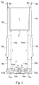
- Fig. 1 presents a simplified and diagrammatic side view of one elevator arrangement applicable to the solution according to the invention.
- the elevator arrangement according to Fig. 1 comprises two compensating weights 3a and 3b functioning as counterweights and disposed symmetrically on different sides of the elevator car 1, both of which compensating weights are connected by means of suspension members 4a and 4b to a car sling 2 fitted around the elevator car 1.
- One suspension member 4a, 4b can be e.g. just an individual rope, belt or chain, or it can be composed of a number of parallel members, e.g. hoisting ropes.
- the suspension members 4a, 4b are e.g.
- a motor module 7 is fitted in the bottom part of the elevator hoistway, which motor module comprises at least a hoisting machine 9 arranged to move the elevator car 1 and provided with a traction sheave 8, as well as two diverting pulleys 10a and 10b.
- the arrangement also comprises two extension modules 11a and 11b, which are fitted at the edges of the elevator hoistway on opposite sides of the motor module 7 to each other. Both extension modules comprise at least two diverting pulleys, which are arranged to guide the traction members 14a and 14b.
- the first traction member 14a is fixed at its first end to the bottom part of the first compensating weight 3a, from where it is led down to pass around the bottom of the first diverting pulley 12a of the first extension module 11a, from where onwards under the first diverting pulley 10a of the motor module 7, after which over the traction sheave 8.
- the first traction member 14a is led to pass around the bottom of the second diverting pulley 10b of the motor module 7, from where onwards under the second diverting pulley 13b of the second extension module 11b, after passing around the bottom of which diverting pulley 13b the traction member 14a is led up to the car sling 2, to the bottom part of which the first traction member 14a is fixed e.g. via a fixing means provided with e.g. spring tensioning or constant-force tensioning.
- the second traction member 14b is, for its part, fixed at its first end to the bottom part of the second compensating weight 3b, from where it is led down to pass around the bottom of the first diverting pulley 12b of the second extension module 11b, from where onwards over the second diverting pulley 10b of the motor module 7, after which under the traction sheave 8.
- the second traction member 14b is led to pass around the top of the first diverting pulley 13a of the, motor module 7, from where onwards under the second diverting pulley 13a of the first extension module 11a, after passing around the bottom of which diverting pulley 13a the traction member 14b is led up to the car sling 2, to the bottom part of which the second traction member 14b is fixed e.g. via a fixing means provided with e.g. spring tensioning or constant-force tensioning.
- Fig. 2 presents a simplified and diagrammatic top view of an elevator arrangement according to Fig. 1 .
- the elevator car 1 is fitted inside the car sling 2.
- Essentially vertical guide rails 17 are fixed by the aid of clamps 16 to the side walls of the elevator hoistway 15, guided by which guide rails the elevator car 1 is arranged to travel up and own in the hoistway 15.
- On both sides of the elevator car 1 are two guide rails 17 that are essentially similar to each other and are fitted symmetrically with respect to each other and to the elevator car 1.
- the guide rails 17 are disposed symmetrically as viewed from above in relation both to the depth center line 1a of the elevator car running through the center point of the elevator car 1 and to the width center line 1b of the elevator car running through the center point of the elevator car 1.
- Compensating weights 3a, 3b are fitted between the guide rails 17 on both sides of the elevator car 1, at least one compensating weight each side of the elevator car 1, which compensating weights 3a, 3b are configured to travel in the hoistway 15 resting on the first outer surfaces, which are opposite each other, of the guide rails 17.
- the compensating weights 3a, 3b are, however, for the sake of clarity presented as slightly detached from the aforementioned outer surfaces, which are opposite to each other, of the guide rails 17.
- the elevator car 1 is configured to rest, by the aid of roller guide shoes 18 fixed to the car sling 2, on the second outer surfaces of the guide rails 17, which surfaces point away from each other.
- the suspension members 4a, 4b of the elevator car 1 are arranged to be fixed at their first ends to the top parts of the compensating weights 3a, 3b and at their second ends to the fixing means 6a, 6b on the car sling 2.
- the fixing points of the suspension members 4a, 4b are marked in the figure with the number 19.
- the suspension and the guidance of the vertical movement of the elevator car 1 is implemented symmetrically with respect to the center lines 1a and 1b, in which case no additional stresses or strains are exerted e.g. on the guide rails 17 and other hoistway structures.
- Fig. 3 presents a simplified and diagrammatic top view of the top part of the elevator hoistway 15. Diverting pulleys 5a and 5b are fitted in the top part of the elevator hoistway 15 on opposite sides of the elevator car 1 in the lateral direction.
- first diverting pulleys 5a symmetrically on different sides of the depth center line 1a of the elevator car.
- second diverting pulleys 5b symmetrically on different sides of the depth center line 1a of the elevator car 1.
- diverting pulleys 5a and 5b are disposed symmetrically to each other in relation to the width center line 1b of the elevator car 1.
- the suspension members 4a, 4b of the elevator car 1 are led over the diverting pulleys 5a, 5b from the compensating weights 3a, 3b to the elevator car 1, as is already described in the descriptive part of Fig, 1 .
- Fig. 4 presents an oblique view from the side and top of a suspension arrangement of the compensating weights of the elevator arrangement presented above.
- Fig. 4 presents only the first compensating weight 3a, because the second compensating weight 3b is suspended in the same way.
- the elevator car 1 is in its bottom position and the compensating weights 3a and 3b are in their top position near the diverting pulleys 5a and 5b.
- the first suspension members 4a which are thus at least two belts, ropes or two pluralities of parallel ropes, leaving from the compensating weight 3a each pass around the top of their own diverting pulley 5a and then descend to their fixing points 19 on the elevator car 1.
- the suspension members 4b on the second side of the elevator car 1 are suspended in a corresponding manner.
- Fig. 5 presents a simplified and diagrammatic top view of the bottom part of the elevator hoistway 15.
- the diverting pulleys in the bottom part of the hoistway are not presented, and the traction members 14a and 14b are presented as cross-sections.
- the traction members 14a and 14b are preferably e.g. toothed belts, which are configured to travel a part of the distance parallel with each other and symmetrically to each other on both sides of the depth center line 1a of the elevator car 1.
- the traction member 14a is disposed on a first side of the depth center line 1a of the elevator car 1 and the traction member 14b is disposed on a second side of the depth center line 1a of the elevator car 1.
- the horizontal distances of the traction members 14a and 14b are symmetrically disposed from the width center line 1b of the elevator car 1.
- the toothed contact surface of the traction sheave 8 is so wide that both the traction members 14a, 14b fit side-by-side onto the contact surface of the traction sheave 8 without interfering with each other. In this way one and the same hoisting machine 9 and also one and the same traction sheave 8 give to both the traction members 14a, 14b a force producing linear movement of the elevator car 1 and of the compensating weights 3a, 3b.
- Fig. 6 presents a simplified, magnified and diagrammatic top view of the guide rail structures and guide shoe structures of an elevator arrangement according to Fig. 1 , the structure and operation of which have been described already in conjunction with Fig. 2 .
- the clamps 16 are presented slightly detached from the side wall of the elevator hoistway 15, although in reality they are attached to the side wall.
- the guide rail 17 of the elevator car 1 is in its cross-section essentially a U-shaped beam, which opens towards the elevator car 1.
- the compensating weights 3a and 3b disposed between the guide rails 17 are configured to travel in the hoistway 15 resting on the first outer surfaces, which are opposite each other, of the web of the guide rails 17.
- the compensating weight 3a is presented in Fig. 6 slightly detached from the aforementioned outer surface of the guide rails 17.
- the elevator car 1 is configured to rest, by the aid of roller guide shoes 18 fixed to the car sling 2, on the second outer surfaces of the guide rails 17, which surfaces point away from each other.
- Flanges turned outwards from the web of the guide rail at a right angle with respect to the web of the guide rail 17, are additionally on the guide rail 17 on the side of the elevator car 1, of which the flanges 17a that point towards each other are configured as a fixing surface for an enclosure board 20, with which the compensating weight 3a, 3b is enclosed in its own enclosure. Good enclosing reduces the noise disturbance when, inter alia, the elevator car 1 and the compensating weights 3a, 3b meet each other in the elevator hoistway.
- the positioning point of the diverting pulleys 5a, 5b disposed in the top clearance of the elevator hoistway 15 is configured such that the elevator car 1 can rise past the diverting pulleys 5a, 5b in the top end of the elevator hoistway 15 right to the top end of the elevator hoistway 15. In this way the most space-efficient layout solution possible is also achieved in the top end of the elevator hoistway 15.
- the hoisting machine can be on the base of the elevator hoistway, or close to the base, but also on some side of the elevator hoistway and also in the top part of the elevator hoistway.
- the number of compensating weights can also be greater than two. There can be e.g. three, four, six, eight, ten or even more compensating weights disposed in a different manner.
Landscapes
- Engineering & Computer Science (AREA)
- Civil Engineering (AREA)
- Mechanical Engineering (AREA)
- Structural Engineering (AREA)
- Lift-Guide Devices, And Elevator Ropes And Cables (AREA)
Applications Claiming Priority (2)
| Application Number | Priority Date | Filing Date | Title |
|---|---|---|---|
| FI20115902A FI125114B (fi) | 2011-09-15 | 2011-09-15 | Hissin ripustus- ja ohjainjärjestely |
| PCT/FI2012/050809 WO2013038050A1 (en) | 2011-09-15 | 2012-08-24 | Suspension arrangement and guide shoe arrangement for an elevator |
Publications (3)
| Publication Number | Publication Date |
|---|---|
| EP2755907A1 EP2755907A1 (en) | 2014-07-23 |
| EP2755907A4 EP2755907A4 (en) | 2015-05-06 |
| EP2755907B1 true EP2755907B1 (en) | 2016-01-20 |
Family
ID=44718809
Family Applications (1)
| Application Number | Title | Priority Date | Filing Date |
|---|---|---|---|
| EP12832049.6A Not-in-force EP2755907B1 (en) | 2011-09-15 | 2012-08-24 | Suspension arrangement and guide shoe arrangement for an elevator |
Country Status (7)
| Country | Link |
|---|---|
| US (1) | US9546076B2 (https=) |
| EP (1) | EP2755907B1 (https=) |
| JP (1) | JP5889412B2 (https=) |
| CN (1) | CN103796942B (https=) |
| EA (1) | EA025387B1 (https=) |
| FI (1) | FI125114B (https=) |
| WO (1) | WO2013038050A1 (https=) |
Families Citing this family (12)
| Publication number | Priority date | Publication date | Assignee | Title |
|---|---|---|---|---|
| FI125157B (fi) * | 2011-11-08 | 2015-06-15 | Kone Corp | Hissijärjestelmä |
| CN104590975B (zh) * | 2014-12-23 | 2017-07-11 | 湖州南浔固源电梯部件有限公司 | 提高杂物梯综合性能的方法 |
| EP3288887A4 (en) * | 2015-04-27 | 2019-03-13 | KONE Corporation | ARRANGEMENT FOR ADJUSTING THE VOLTAGE OF A TRACTION ELEMENT OF AN ELEVATOR |
| CN107416618A (zh) * | 2017-06-03 | 2017-12-01 | 福州幻科机电科技有限公司 | 一种带有智能投递到户的快件专用升降电梯 |
| WO2019059840A1 (en) * | 2017-09-20 | 2019-03-28 | Singapore Lift Company Pte Ltd | APPARATUS FOR LOCATING A LIFT COUNTERWEIGHT AND ITS MOUNTING METHOD |
| US10941020B2 (en) | 2018-01-30 | 2021-03-09 | Otis Elevator Company | Deflector sheave bracket for offset bedplate |
| CN108439135A (zh) * | 2018-03-30 | 2018-08-24 | 江苏兴华胶带股份有限公司 | 一种新型电梯补偿缆无损运行导向装置 |
| SG11202106078YA (en) * | 2018-12-20 | 2021-07-29 | Inventio Ag | Lift rail |
| CN113439065B (zh) * | 2019-03-05 | 2023-05-30 | 因温特奥股份公司 | 用于测量电梯竖井的测量装置及测量装置用于测量的电梯竖井的用途 |
| WO2021186493A1 (ja) * | 2020-03-16 | 2021-09-23 | 株式会社日立製作所 | 工事用エレベーター装置 |
| RU2753040C1 (ru) * | 2020-12-21 | 2021-08-11 | федеральное государственное бюджетное образовательное учреждение высшего образования "Волгоградский государственный аграрный университет" (ФГБОУ ВО Волгоградский ГАУ) | Погрузочно-транспортный агрегат |
| CN116177345B (zh) * | 2023-02-14 | 2025-08-01 | 东莞市尚家电梯科技有限公司 | 一种强驱电梯结构 |
Family Cites Families (57)
| Publication number | Priority date | Publication date | Assignee | Title |
|---|---|---|---|---|
| US684390A (en) | 1899-12-09 | 1901-10-08 | Otis Elevator Co | Elevator apparatus. |
| US811513A (en) | 1902-06-23 | 1906-01-30 | Elevator Securities Company | Elevator. |
| US735093A (en) | 1903-01-31 | 1903-08-04 | Oscar Greenwald | Elevator-cable guard. |
| US1132769A (en) * | 1907-06-17 | 1915-03-23 | Otis Elevator Co | Traction-elevator. |
| US987384A (en) | 1908-12-15 | 1911-03-21 | Otis Elevator Co | Rope-drive elevator. |
| US1051335A (en) * | 1912-04-17 | 1913-01-21 | William Francis King | Dumb-waiter guide. |
| US1566385A (en) | 1922-12-15 | 1925-12-22 | Otis Elevator Co | Control system for elevators |
| US1702783A (en) * | 1928-03-09 | 1929-02-19 | Le Roy H Kiesling | Elevator guide means |
| US3174585A (en) * | 1962-08-13 | 1965-03-23 | Otis Elevator Co | Elevator hoisting mechanism |
| FR1397440A (fr) * | 1964-03-19 | 1965-04-30 | Cie Generale Des Parkings Auto | Perfectionnements apportés aux appareils élévateurs à charge suspendue |
| DE1506479A1 (de) * | 1967-06-14 | 1969-12-18 | Hans Mangelsdorff | Elastischer Triebstock-Kettenantrieb,insbesondere fuer Industrie- und Garagenaufzuege |
| US3845842A (en) * | 1973-06-13 | 1974-11-05 | W Johnson | Elevator system |
| JPS5257644A (en) | 1975-11-05 | 1977-05-12 | Hitachi Ltd | Observation elevator |
| JPH0449179U (https=) * | 1990-08-30 | 1992-04-24 | ||
| JPH0742063B2 (ja) * | 1992-07-17 | 1995-05-10 | 三菱電機株式会社 | エレベータ駆動システム |
| JP2536816B2 (ja) * | 1994-02-25 | 1996-09-25 | 光洋自動機株式会社 | 昇降装置 |
| US5699879A (en) * | 1996-05-06 | 1997-12-23 | Sakita; Masami | Elevator system |
| JPH09328270A (ja) * | 1996-06-11 | 1997-12-22 | Hitachi Building Syst Co Ltd | エレベータ装置 |
| WO1998029326A1 (en) | 1996-12-30 | 1998-07-09 | Kone Corporation | Elevator rope arrangement |
| AU7890098A (en) | 1996-12-30 | 1998-07-31 | Kone Corporation | Elevator rope arrangement |
| US6401871B2 (en) | 1998-02-26 | 2002-06-11 | Otis Elevator Company | Tension member for an elevator |
| US6488124B1 (en) | 1997-09-26 | 2002-12-03 | Kabushiki Kaisha Toshiba | Elevator |
| US7299896B1 (en) * | 1998-09-29 | 2007-11-27 | Otis Elevator Company | Elevator system having drive motor located adjacent to hoistway door |
| WO1999043600A1 (en) | 1998-02-26 | 1999-09-02 | Otis Elevator Company | Elevator system having drive motor located at the bottom portion of the hoistway |
| WO1999043599A1 (en) | 1998-02-26 | 1999-09-02 | Otis Elevator Company | Drum drive elevator using flat belt |
| WO1999043885A1 (en) | 1998-02-26 | 1999-09-02 | Otis Elevator Company | Tension member for an elevator |
| JP2002504473A (ja) | 1998-02-26 | 2002-02-12 | オーチス エレベータ カンパニー | 平形の可撓性ロープを使用する二重綱車ロープ式のエレベータ装置 |
| US6247557B1 (en) | 1998-04-28 | 2001-06-19 | Kabushiki Kaisha Toshiba | Traction type elevator apparatus |
| JP4317603B2 (ja) * | 1998-09-16 | 2009-08-19 | 見敏 石井 | エレベータ装置 |
| US6305499B1 (en) | 1998-09-30 | 2001-10-23 | Otis Elevator Company | Drum drive elevator using flat belt |
| US6848543B2 (en) * | 1998-10-30 | 2005-02-01 | Otis Elevator Company | Single wall interface traction elevator |
| ES2161183B1 (es) * | 1998-12-22 | 2002-08-01 | Otis Elevator Co | "maquina plana de ascensor que tiene rotacion orientada verticalmente.". |
| US6481538B2 (en) * | 2000-08-30 | 2002-11-19 | Otis Elevator Company | Elevator guide rail mounting assembly |
| FR2813874B1 (fr) | 2000-09-08 | 2003-01-31 | Sodimas | Installation d'ascenseur pourvue de moyens d'entrainement et de moyens de suspension independants |
| BR0114189B1 (pt) | 2000-09-27 | 2010-03-09 | elevador com unidade de acionamento, disposta dentro do poço do elevador acima lateralmente. | |
| JP2002167137A (ja) | 2000-11-29 | 2002-06-11 | Toshiba Corp | エレベータ |
| JP4771586B2 (ja) * | 2000-12-08 | 2011-09-14 | 東芝エレベータ株式会社 | エレベータ |
| FR2823734B1 (fr) | 2001-04-19 | 2007-04-20 | Serge Arnoult | Installation d'ascenseur pourvue de moyens d'entrainement et de moyens de suspension independants |
| DE50209383D1 (de) * | 2001-11-23 | 2007-03-15 | Inventio Ag | Aufzug mit riemenartigem übertragungsmittel, insbesondere mit zahnriemen, als tragmittel und/oder treibmittel |
| JP2005509578A (ja) * | 2001-11-23 | 2005-04-14 | インベンテイオ・アクテイエンゲゼルシヤフト | ベルト状動力伝達手段、特に支持および/または駆動手段としてのくさび形リブ付きベルトを有するエレベータ |
| JP2004001912A (ja) * | 2002-05-30 | 2004-01-08 | Otis Elevator Co | エレベータ装置 |
| CN1289380C (zh) * | 2003-06-24 | 2006-12-13 | 上海三菱电梯有限公司 | 电梯 |
| ITBO20030413A1 (it) | 2003-07-03 | 2005-01-04 | Sassi Alberto Spa | Unita' di movimentazione per ascensori e montacarichi. |
| MXPA03009456A (es) | 2003-10-16 | 2005-04-21 | Luis Rodolfo Zamorano Morfin | Mejoras para elevador de pasajeros o carga con base al uso de cadenas, contrapesos y servomotores. |
| CN100572248C (zh) | 2003-12-09 | 2009-12-23 | 三菱电机株式会社 | 电梯装置 |
| JPWO2005056455A1 (ja) | 2003-12-09 | 2007-07-05 | 三菱電機株式会社 | エレベータ装置 |
| JP4558336B2 (ja) | 2004-01-20 | 2010-10-06 | 三菱電機株式会社 | エレベータの駆動装置 |
| WO2006040813A1 (ja) * | 2004-10-13 | 2006-04-20 | Mitsubishi Denki Kabushiki Kaisha | エレベータ装置 |
| EP1760028B1 (en) | 2005-09-06 | 2009-07-22 | Elex Italia S.r.l. | Room-less lifting equipment for persons and goods |
| DE102006037253A1 (de) | 2006-08-09 | 2008-02-14 | Widmann, Manuela | Aufzugsanlage |
| KR20090040752A (ko) | 2007-10-22 | 2009-04-27 | 삼성전자주식회사 | 평판 패널 디스플레이장치의 벽걸이용 지지장치 |
| CN101903278B (zh) | 2007-12-21 | 2013-04-03 | 因温特奥股份公司 | 具有两个电梯轿厢的电梯设备 |
| JP5486798B2 (ja) * | 2008-12-24 | 2014-05-07 | 株式会社日立製作所 | エレベーター装置 |
| CN201400508Y (zh) * | 2009-03-02 | 2010-02-10 | 日立电梯(中国)有限公司 | 无机房电梯 |
| WO2011099278A1 (ja) * | 2010-02-10 | 2011-08-18 | Haraguchi Osamu | エレベータ |
| FI124541B (fi) * | 2011-05-18 | 2014-10-15 | Kone Corp | Hissijärjestely |
| FI20115641A7 (fi) | 2011-06-22 | 2012-12-23 | Kone Corp | Hissin vetoelimen kiristysjärjestely |
-
2011
- 2011-09-15 FI FI20115902A patent/FI125114B/fi not_active IP Right Cessation
-
2012
- 2012-08-24 JP JP2014530284A patent/JP5889412B2/ja not_active Expired - Fee Related
- 2012-08-24 WO PCT/FI2012/050809 patent/WO2013038050A1/en not_active Ceased
- 2012-08-24 EP EP12832049.6A patent/EP2755907B1/en not_active Not-in-force
- 2012-08-24 CN CN201280044911.3A patent/CN103796942B/zh not_active Expired - Fee Related
- 2012-08-24 EA EA201490356A patent/EA025387B1/ru not_active IP Right Cessation
-
2014
- 2014-02-28 US US14/193,444 patent/US9546076B2/en not_active Expired - Fee Related
Also Published As
| Publication number | Publication date |
|---|---|
| EA201490356A1 (ru) | 2014-08-29 |
| FI125114B (fi) | 2015-06-15 |
| FI20115902A0 (fi) | 2011-09-15 |
| EP2755907A4 (en) | 2015-05-06 |
| US9546076B2 (en) | 2017-01-17 |
| WO2013038050A1 (en) | 2013-03-21 |
| US20140174859A1 (en) | 2014-06-26 |
| EA025387B1 (ru) | 2016-12-30 |
| JP5889412B2 (ja) | 2016-03-22 |
| JP2014526427A (ja) | 2014-10-06 |
| CN103796942A (zh) | 2014-05-14 |
| FI20115902L (fi) | 2013-03-16 |
| EP2755907A1 (en) | 2014-07-23 |
| CN103796942B (zh) | 2016-08-17 |
Similar Documents
| Publication | Publication Date | Title |
|---|---|---|
| EP2755907B1 (en) | Suspension arrangement and guide shoe arrangement for an elevator | |
| US9643817B2 (en) | Elevator arrangement | |
| US9758346B2 (en) | Tensioning arrangement for a traction means of an elevator | |
| US8448323B2 (en) | Method for modernizing an elevator | |
| TWI419828B (zh) | 具有二台升降機之升降裝置 | |
| EP3722242B1 (en) | Elevator for particularly small elevator shafts | |
| CN1882492B (zh) | 电梯滑轮装置 | |
| EP2776355B1 (en) | Elevator system | |
| CN1934022B (zh) | 电梯 | |
| WO2011117458A1 (en) | Arrangement for damping lateral sways of a rope-like means fixed to an elevator car | |
| US9580277B2 (en) | Elevator car suspension | |
| CA2545985A1 (en) | Elevator rope compensation device | |
| US8127893B2 (en) | Elevator and arrangement | |
| EP1828044B1 (en) | Elevator roping arrangement | |
| KR20080055705A (ko) | 승강기 설비 | |
| WO2013026960A1 (en) | Compensating arrangement for the suspension members of an elevator | |
| JP2025184539A (ja) | エレベーター装置 | |
| EP2509907B1 (en) | Suspension arrangement of an elevator car | |
| KR20060005999A (ko) | 엘리베이터 장치 | |
| WO2018078211A1 (en) | Elevator and elevator car roof railing | |
| HK1100552B (zh) | 电梯滑轮装置 | |
| KR20070065322A (ko) | 엘리베이터 장치 |
Legal Events
| Date | Code | Title | Description |
|---|---|---|---|
| PUAI | Public reference made under article 153(3) epc to a published international application that has entered the european phase |
Free format text: ORIGINAL CODE: 0009012 |
|
| 17P | Request for examination filed |
Effective date: 20140224 |
|
| AK | Designated contracting states |
Kind code of ref document: A1 Designated state(s): AL AT BE BG CH CY CZ DE DK EE ES FI FR GB GR HR HU IE IS IT LI LT LU LV MC MK MT NL NO PL PT RO RS SE SI SK SM TR |
|
| DAX | Request for extension of the european patent (deleted) | ||
| RA4 | Supplementary search report drawn up and despatched (corrected) |
Effective date: 20150409 |
|
| RIC1 | Information provided on ipc code assigned before grant |
Ipc: B66B 7/02 20060101AFI20150401BHEP Ipc: B66B 7/06 20060101ALI20150401BHEP Ipc: B66B 11/00 20060101ALI20150401BHEP |
|
| GRAP | Despatch of communication of intention to grant a patent |
Free format text: ORIGINAL CODE: EPIDOSNIGR1 |
|
| RIC1 | Information provided on ipc code assigned before grant |
Ipc: B66B 7/02 20060101AFI20150731BHEP Ipc: B66B 11/00 20060101ALI20150731BHEP |
|
| INTG | Intention to grant announced |
Effective date: 20150910 |
|
| GRAS | Grant fee paid |
Free format text: ORIGINAL CODE: EPIDOSNIGR3 |
|
| GRAA | (expected) grant |
Free format text: ORIGINAL CODE: 0009210 |
|
| RIN1 | Information on inventor provided before grant (corrected) |
Inventor name: RAESAENEN, MATTI Inventor name: MIKKONEN, JANNE Inventor name: JUURIOKSA, MARTTI |
|
| AK | Designated contracting states |
Kind code of ref document: B1 Designated state(s): AL AT BE BG CH CY CZ DE DK EE ES FI FR GB GR HR HU IE IS IT LI LT LU LV MC MK MT NL NO PL PT RO RS SE SI SK SM TR |
|
| REG | Reference to a national code |
Ref country code: GB Ref legal event code: FG4D |
|
| REG | Reference to a national code |
Ref country code: CH Ref legal event code: EP |
|
| REG | Reference to a national code |
Ref country code: IE Ref legal event code: FG4D |
|
| REG | Reference to a national code |
Ref country code: AT Ref legal event code: REF Ref document number: 771631 Country of ref document: AT Kind code of ref document: T Effective date: 20160215 |
|
| REG | Reference to a national code |
Ref country code: DE Ref legal event code: R096 Ref document number: 602012014239 Country of ref document: DE |
|
| REG | Reference to a national code |
Ref country code: LT Ref legal event code: MG4D Ref country code: NL Ref legal event code: MP Effective date: 20160120 |
|
| REG | Reference to a national code |
Ref country code: AT Ref legal event code: MK05 Ref document number: 771631 Country of ref document: AT Kind code of ref document: T Effective date: 20160120 |
|
| PG25 | Lapsed in a contracting state [announced via postgrant information from national office to epo] |
Ref country code: NL Free format text: LAPSE BECAUSE OF FAILURE TO SUBMIT A TRANSLATION OF THE DESCRIPTION OR TO PAY THE FEE WITHIN THE PRESCRIBED TIME-LIMIT Effective date: 20160120 |
|
| PG25 | Lapsed in a contracting state [announced via postgrant information from national office to epo] |
Ref country code: ES Free format text: LAPSE BECAUSE OF FAILURE TO SUBMIT A TRANSLATION OF THE DESCRIPTION OR TO PAY THE FEE WITHIN THE PRESCRIBED TIME-LIMIT Effective date: 20160120 Ref country code: GR Free format text: LAPSE BECAUSE OF FAILURE TO SUBMIT A TRANSLATION OF THE DESCRIPTION OR TO PAY THE FEE WITHIN THE PRESCRIBED TIME-LIMIT Effective date: 20160421 Ref country code: NO Free format text: LAPSE BECAUSE OF FAILURE TO SUBMIT A TRANSLATION OF THE DESCRIPTION OR TO PAY THE FEE WITHIN THE PRESCRIBED TIME-LIMIT Effective date: 20160420 Ref country code: HR Free format text: LAPSE BECAUSE OF FAILURE TO SUBMIT A TRANSLATION OF THE DESCRIPTION OR TO PAY THE FEE WITHIN THE PRESCRIBED TIME-LIMIT Effective date: 20160120 Ref country code: FI Free format text: LAPSE BECAUSE OF FAILURE TO SUBMIT A TRANSLATION OF THE DESCRIPTION OR TO PAY THE FEE WITHIN THE PRESCRIBED TIME-LIMIT Effective date: 20160120 Ref country code: IT Free format text: LAPSE BECAUSE OF FAILURE TO SUBMIT A TRANSLATION OF THE DESCRIPTION OR TO PAY THE FEE WITHIN THE PRESCRIBED TIME-LIMIT Effective date: 20160120 |
|
| REG | Reference to a national code |
Ref country code: FR Ref legal event code: PLFP Year of fee payment: 5 |
|
| PG25 | Lapsed in a contracting state [announced via postgrant information from national office to epo] |
Ref country code: AT Free format text: LAPSE BECAUSE OF FAILURE TO SUBMIT A TRANSLATION OF THE DESCRIPTION OR TO PAY THE FEE WITHIN THE PRESCRIBED TIME-LIMIT Effective date: 20160120 Ref country code: PL Free format text: LAPSE BECAUSE OF FAILURE TO SUBMIT A TRANSLATION OF THE DESCRIPTION OR TO PAY THE FEE WITHIN THE PRESCRIBED TIME-LIMIT Effective date: 20160120 Ref country code: RS Free format text: LAPSE BECAUSE OF FAILURE TO SUBMIT A TRANSLATION OF THE DESCRIPTION OR TO PAY THE FEE WITHIN THE PRESCRIBED TIME-LIMIT Effective date: 20160120 Ref country code: LT Free format text: LAPSE BECAUSE OF FAILURE TO SUBMIT A TRANSLATION OF THE DESCRIPTION OR TO PAY THE FEE WITHIN THE PRESCRIBED TIME-LIMIT Effective date: 20160120 Ref country code: LV Free format text: LAPSE BECAUSE OF FAILURE TO SUBMIT A TRANSLATION OF THE DESCRIPTION OR TO PAY THE FEE WITHIN THE PRESCRIBED TIME-LIMIT Effective date: 20160120 Ref country code: IS Free format text: LAPSE BECAUSE OF FAILURE TO SUBMIT A TRANSLATION OF THE DESCRIPTION OR TO PAY THE FEE WITHIN THE PRESCRIBED TIME-LIMIT Effective date: 20160520 Ref country code: SE Free format text: LAPSE BECAUSE OF FAILURE TO SUBMIT A TRANSLATION OF THE DESCRIPTION OR TO PAY THE FEE WITHIN THE PRESCRIBED TIME-LIMIT Effective date: 20160120 Ref country code: PT Free format text: LAPSE BECAUSE OF FAILURE TO SUBMIT A TRANSLATION OF THE DESCRIPTION OR TO PAY THE FEE WITHIN THE PRESCRIBED TIME-LIMIT Effective date: 20160520 |
|
| REG | Reference to a national code |
Ref country code: DE Ref legal event code: R097 Ref document number: 602012014239 Country of ref document: DE |
|
| PG25 | Lapsed in a contracting state [announced via postgrant information from national office to epo] |
Ref country code: DK Free format text: LAPSE BECAUSE OF FAILURE TO SUBMIT A TRANSLATION OF THE DESCRIPTION OR TO PAY THE FEE WITHIN THE PRESCRIBED TIME-LIMIT Effective date: 20160120 Ref country code: EE Free format text: LAPSE BECAUSE OF FAILURE TO SUBMIT A TRANSLATION OF THE DESCRIPTION OR TO PAY THE FEE WITHIN THE PRESCRIBED TIME-LIMIT Effective date: 20160120 |
|
| PLBE | No opposition filed within time limit |
Free format text: ORIGINAL CODE: 0009261 |
|
| STAA | Information on the status of an ep patent application or granted ep patent |
Free format text: STATUS: NO OPPOSITION FILED WITHIN TIME LIMIT |
|
| PG25 | Lapsed in a contracting state [announced via postgrant information from national office to epo] |
Ref country code: CZ Free format text: LAPSE BECAUSE OF FAILURE TO SUBMIT A TRANSLATION OF THE DESCRIPTION OR TO PAY THE FEE WITHIN THE PRESCRIBED TIME-LIMIT Effective date: 20160120 Ref country code: SM Free format text: LAPSE BECAUSE OF FAILURE TO SUBMIT A TRANSLATION OF THE DESCRIPTION OR TO PAY THE FEE WITHIN THE PRESCRIBED TIME-LIMIT Effective date: 20160120 Ref country code: SK Free format text: LAPSE BECAUSE OF FAILURE TO SUBMIT A TRANSLATION OF THE DESCRIPTION OR TO PAY THE FEE WITHIN THE PRESCRIBED TIME-LIMIT Effective date: 20160120 Ref country code: RO Free format text: LAPSE BECAUSE OF FAILURE TO SUBMIT A TRANSLATION OF THE DESCRIPTION OR TO PAY THE FEE WITHIN THE PRESCRIBED TIME-LIMIT Effective date: 20160120 |
|
| 26N | No opposition filed |
Effective date: 20161021 |
|
| PG25 | Lapsed in a contracting state [announced via postgrant information from national office to epo] |
Ref country code: BE Free format text: LAPSE BECAUSE OF FAILURE TO SUBMIT A TRANSLATION OF THE DESCRIPTION OR TO PAY THE FEE WITHIN THE PRESCRIBED TIME-LIMIT Effective date: 20160120 |
|
| PG25 | Lapsed in a contracting state [announced via postgrant information from national office to epo] |
Ref country code: SI Free format text: LAPSE BECAUSE OF FAILURE TO SUBMIT A TRANSLATION OF THE DESCRIPTION OR TO PAY THE FEE WITHIN THE PRESCRIBED TIME-LIMIT Effective date: 20160120 Ref country code: BG Free format text: LAPSE BECAUSE OF FAILURE TO SUBMIT A TRANSLATION OF THE DESCRIPTION OR TO PAY THE FEE WITHIN THE PRESCRIBED TIME-LIMIT Effective date: 20160420 |
|
| PG25 | Lapsed in a contracting state [announced via postgrant information from national office to epo] |
Ref country code: MC Free format text: LAPSE BECAUSE OF FAILURE TO SUBMIT A TRANSLATION OF THE DESCRIPTION OR TO PAY THE FEE WITHIN THE PRESCRIBED TIME-LIMIT Effective date: 20160120 |
|
| REG | Reference to a national code |
Ref country code: CH Ref legal event code: PL |
|
| PG25 | Lapsed in a contracting state [announced via postgrant information from national office to epo] |
Ref country code: CH Free format text: LAPSE BECAUSE OF NON-PAYMENT OF DUE FEES Effective date: 20160831 Ref country code: LI Free format text: LAPSE BECAUSE OF NON-PAYMENT OF DUE FEES Effective date: 20160831 |
|
| REG | Reference to a national code |
Ref country code: IE Ref legal event code: MM4A |
|
| PG25 | Lapsed in a contracting state [announced via postgrant information from national office to epo] |
Ref country code: IE Free format text: LAPSE BECAUSE OF NON-PAYMENT OF DUE FEES Effective date: 20160824 |
|
| REG | Reference to a national code |
Ref country code: FR Ref legal event code: PLFP Year of fee payment: 6 |
|
| PG25 | Lapsed in a contracting state [announced via postgrant information from national office to epo] |
Ref country code: LU Free format text: LAPSE BECAUSE OF NON-PAYMENT OF DUE FEES Effective date: 20160824 |
|
| PG25 | Lapsed in a contracting state [announced via postgrant information from national office to epo] |
Ref country code: HU Free format text: LAPSE BECAUSE OF FAILURE TO SUBMIT A TRANSLATION OF THE DESCRIPTION OR TO PAY THE FEE WITHIN THE PRESCRIBED TIME-LIMIT; INVALID AB INITIO Effective date: 20120824 |
|
| PG25 | Lapsed in a contracting state [announced via postgrant information from national office to epo] |
Ref country code: CY Free format text: LAPSE BECAUSE OF FAILURE TO SUBMIT A TRANSLATION OF THE DESCRIPTION OR TO PAY THE FEE WITHIN THE PRESCRIBED TIME-LIMIT Effective date: 20160120 Ref country code: MK Free format text: LAPSE BECAUSE OF FAILURE TO SUBMIT A TRANSLATION OF THE DESCRIPTION OR TO PAY THE FEE WITHIN THE PRESCRIBED TIME-LIMIT Effective date: 20160120 Ref country code: MT Free format text: LAPSE BECAUSE OF NON-PAYMENT OF DUE FEES Effective date: 20160831 |
|
| REG | Reference to a national code |
Ref country code: FR Ref legal event code: PLFP Year of fee payment: 7 |
|
| PG25 | Lapsed in a contracting state [announced via postgrant information from national office to epo] |
Ref country code: TR Free format text: LAPSE BECAUSE OF FAILURE TO SUBMIT A TRANSLATION OF THE DESCRIPTION OR TO PAY THE FEE WITHIN THE PRESCRIBED TIME-LIMIT Effective date: 20160120 Ref country code: AL Free format text: LAPSE BECAUSE OF FAILURE TO SUBMIT A TRANSLATION OF THE DESCRIPTION OR TO PAY THE FEE WITHIN THE PRESCRIBED TIME-LIMIT Effective date: 20160120 |
|
| PGFP | Annual fee paid to national office [announced via postgrant information from national office to epo] |
Ref country code: FR Payment date: 20200821 Year of fee payment: 9 Ref country code: GB Payment date: 20200826 Year of fee payment: 9 Ref country code: DE Payment date: 20200819 Year of fee payment: 9 |
|
| REG | Reference to a national code |
Ref country code: DE Ref legal event code: R119 Ref document number: 602012014239 Country of ref document: DE |
|
| GBPC | Gb: european patent ceased through non-payment of renewal fee |
Effective date: 20210824 |
|
| PG25 | Lapsed in a contracting state [announced via postgrant information from national office to epo] |
Ref country code: GB Free format text: LAPSE BECAUSE OF NON-PAYMENT OF DUE FEES Effective date: 20210824 Ref country code: FR Free format text: LAPSE BECAUSE OF NON-PAYMENT OF DUE FEES Effective date: 20210831 Ref country code: DE Free format text: LAPSE BECAUSE OF NON-PAYMENT OF DUE FEES Effective date: 20220301 |