EP2754834B1 - Wärmedämmleiste und Rahmenprofil für ein Fenster, eine Tür, eine Fassade oder ein Lichtdach - Google Patents
Wärmedämmleiste und Rahmenprofil für ein Fenster, eine Tür, eine Fassade oder ein Lichtdach Download PDFInfo
- Publication number
- EP2754834B1 EP2754834B1 EP13195637.7A EP13195637A EP2754834B1 EP 2754834 B1 EP2754834 B1 EP 2754834B1 EP 13195637 A EP13195637 A EP 13195637A EP 2754834 B1 EP2754834 B1 EP 2754834B1
- Authority
- EP
- European Patent Office
- Prior art keywords
- frame profile
- ribs
- filling element
- web
- heat insulation
- Prior art date
- Legal status (The legal status is an assumption and is not a legal conclusion. Google has not performed a legal analysis and makes no representation as to the accuracy of the status listed.)
- Active
Links
Images


Classifications
-
- E—FIXED CONSTRUCTIONS
- E06—DOORS, WINDOWS, SHUTTERS, OR ROLLER BLINDS IN GENERAL; LADDERS
- E06B—FIXED OR MOVABLE CLOSURES FOR OPENINGS IN BUILDINGS, VEHICLES, FENCES OR LIKE ENCLOSURES IN GENERAL, e.g. DOORS, WINDOWS, BLINDS, GATES
- E06B3/00—Window sashes, door leaves, or like elements for closing wall or like openings; Layout of fixed or moving closures, e.g. windows in wall or like openings; Features of rigidly-mounted outer frames relating to the mounting of wing frames
- E06B3/04—Wing frames not characterised by the manner of movement
- E06B3/263—Frames with special provision for insulation
- E06B3/26301—Frames with special provision for insulation with prefabricated insulating strips between two metal section members
- E06B3/26303—Frames with special provision for insulation with prefabricated insulating strips between two metal section members with thin strips, e.g. defining a hollow space between the metal section members
-
- E—FIXED CONSTRUCTIONS
- E06—DOORS, WINDOWS, SHUTTERS, OR ROLLER BLINDS IN GENERAL; LADDERS
- E06B—FIXED OR MOVABLE CLOSURES FOR OPENINGS IN BUILDINGS, VEHICLES, FENCES OR LIKE ENCLOSURES IN GENERAL, e.g. DOORS, WINDOWS, BLINDS, GATES
- E06B3/00—Window sashes, door leaves, or like elements for closing wall or like openings; Layout of fixed or moving closures, e.g. windows in wall or like openings; Features of rigidly-mounted outer frames relating to the mounting of wing frames
- E06B3/54—Fixing of glass panes or like plates
- E06B3/5409—Means for locally spacing the pane from the surrounding frame
-
- E—FIXED CONSTRUCTIONS
- E06—DOORS, WINDOWS, SHUTTERS, OR ROLLER BLINDS IN GENERAL; LADDERS
- E06B—FIXED OR MOVABLE CLOSURES FOR OPENINGS IN BUILDINGS, VEHICLES, FENCES OR LIKE ENCLOSURES IN GENERAL, e.g. DOORS, WINDOWS, BLINDS, GATES
- E06B3/00—Window sashes, door leaves, or like elements for closing wall or like openings; Layout of fixed or moving closures, e.g. windows in wall or like openings; Features of rigidly-mounted outer frames relating to the mounting of wing frames
- E06B3/04—Wing frames not characterised by the manner of movement
- E06B3/263—Frames with special provision for insulation
- E06B3/2632—Frames with special provision for insulation with arrangements reducing the heat transmission, other than an interruption in a metal section
- E06B2003/26321—Frames with special provision for insulation with arrangements reducing the heat transmission, other than an interruption in a metal section with additional prefab insulating materials in the hollow space
-
- E—FIXED CONSTRUCTIONS
- E06—DOORS, WINDOWS, SHUTTERS, OR ROLLER BLINDS IN GENERAL; LADDERS
- E06B—FIXED OR MOVABLE CLOSURES FOR OPENINGS IN BUILDINGS, VEHICLES, FENCES OR LIKE ENCLOSURES IN GENERAL, e.g. DOORS, WINDOWS, BLINDS, GATES
- E06B3/00—Window sashes, door leaves, or like elements for closing wall or like openings; Layout of fixed or moving closures, e.g. windows in wall or like openings; Features of rigidly-mounted outer frames relating to the mounting of wing frames
- E06B3/04—Wing frames not characterised by the manner of movement
- E06B3/263—Frames with special provision for insulation
- E06B3/2632—Frames with special provision for insulation with arrangements reducing the heat transmission, other than an interruption in a metal section
- E06B2003/26332—Arrangements reducing the heat transfer in the glazing rabbet or the space between the wing and the casing frame
Definitions
- the present invention relates to a heat-insulating strip for insertion into a gap between a frame profile of a window, a door, a facade or a light roof, and a filling element held on the frame profile according to the preamble of claim 1.
- the DE 20 2005 004 338 U1 discloses a heat-insulating strip for a glass fold, in which a base leg of the heat-insulating strip extends perpendicular to the plane of the insulating glass pane and is provided with an angle leg. Protruding ribs are formed on the base leg and base legs and angle legs are held on the frame profile.
- the EP 1 293 639 discloses a burglar-resistant frame in which a filling element is held at the edge between sealing strips. Front side, the filling element is at least partially supported on the frame via an insertion profile, so that a gap between the frame and filling element is closed in the form of a pressure-resistant backfill.
- the EP 1 988 247 discloses a heat-insulating strip according to the preamble of the claim.
- the DE 10 2006 061 655 discloses a thermal barrier strip having a central land extending perpendicular to the plane of the insulating glass pane. On both sides of the bridge projecting ribs may be provided, the form individual chambers between themselves. Again, the distance between the front side of the insulating glass pane and the frame profile must be set comparatively accurate and there is the problem that the length of the thermal insulation strip must be adapted to the distance between two adjacent locking elements.
- the thermal insulation strip has a central web, on which first ribs are formed on the frame profile and second ribs on the opposite side, wherein the first ribs are arranged offset in the longitudinal direction of the web to the second ribs.
- the heat-insulating strip holds a particularly high elasticity in a direction perpendicular to the longitudinal direction of the web in the plane of the filling element, so that the ribs between the filling element and the frame profile can also rest, so that even large gap distances between the filling element and the frame profile can be bridged.
- the great flexibility of the thermal insulation strip allows the installation of Verklotzungs instituten on the thermal insulation strip, so that the omission of the thermal insulation strip for the installation of the Verklotzungs institute can be omitted.
- the Verklotzungsetti can be placed directly on the heat-insulating strip, wherein the Verklotzungselement can be latched for a positionally accurate alignment of the filling element on the frame profile, and in the region of the Verklotzungsijns the heat-insulating strip is compressed. This saves the cutting of the thermal insulation strip during assembly.
- a receptacle is formed between two ribs on the heat-insulating strip, wherein the receptacle is wider than a rib on the opposite side of the bar.
- the middle bridge can be made of the same elastic Material may be formed as the ribs, in particular of a foamed plastic material.
- the ribs starting from the web towards the outside at least partially tapered. It is also possible for the first ribs to become wider on the side facing the frame profile or to be cuboid in order to obtain a larger contact surface on the frame profile.
- the length of the first and the second ribs is substantially equal, the length should differ in a preferred embodiment by a maximum of 25%, in particular by a maximum of 15%.
- a frame profile is also provided for a window, a door, a facade or a light roof with a filling element held on the frame profile, in which a blocking element is arranged as a spacer between a heat-insulating strip and an end face of the filling element on at least one side of the filling element.
- the heat-insulating strip is then arranged between the blocking element and the frame profile, so that the heat-insulating strip is not recessed in the region of the blocking element. This facilitates the installation and also increases the thermal insulation, since the heat-insulating strip provides a higher thermal insulation as a blocking element.
- the blocking element can compress the heat-insulating strip and be latched, for example, in the region of the frame profile.
- At least one blocking element is provided as a spacer between the heat-insulating strip and the end face of the filling element on each end face of the filling element. Then, the heat-insulating strip can be mounted in four sections, one section for each side, or completely circumferentially on the frame.
- FIG. 1 shows a window 1 with a frame 2, in which an insulating glass pane 3 is arranged as a filling element 3.
- the frame 2 can also be used on a door, a facade or a light roof.
- the frame 2 has two vertical frame profiles 4 and two horizontal frame profiles 5, which are connected to each miter surfaces and have the same cross-section.
- a plurality of locking elements 6 are shown circumferentially schematically, by means of which the position of the filling element 3 can be aligned within the frame 2.
- a thermal insulation strip 7 is shown schematically.
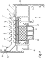
- FIG. 2 is a section through a frame profile 5 shown, which is designed as a composite profile and a first metal shell 50 and a second metal shell 54 which are connected via insulating webs 51 and 52 together. Between the insulating webs 51 and 52, a thermal insulation block 53 is arranged. Based on the filling element 3, the heat-insulating strip 7 is arranged on the inside of the frame profile 5, which is made of a thermal insulation material, in particular a foamed plastic material. The Thermal insulation strip 7 and the central web 8, which is seen in section perpendicular to the plane of the filling element 3 is arranged. At the middle web 8 first ribs 9 are formed on the side facing the frame profile 5 side and on the opposite side second ribs 10 facing the filling element 3.
- the receptacles 11 and 12 are each wider than a rib 9 or 10 on the opposite side. Further, the ribs 9 and 10 are arranged offset to each other, so that in a region of the central web 8 always on one side only a rib 9 or 10 is present.
- the thermal insulation strip 7 further comprises on the inside an angled web 13, which adjoins the central web 8 and is provided on the inside with a detent web 14, which engages in a groove 55 on the metal shell 54 of the frame profile 5.
- a latching web 15 is integrally formed on the central web 8, which engages in a groove 56 on the opposite metal shell 50 of the frame profile 5, so that the heat-insulating strip 7 can be fixed to the frame profile 5 latching.
- the heat-insulating strip 7 in the region of the ribs 9 and 10 in a direction in the plane of the filling element and perpendicular to the web 8 are formed particularly flexible.
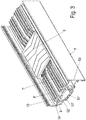
- a Verklotzungselement 6 is arranged on a frame profile 5 ', which is modified in some details relative to the frame profile 5, but can also be designed identical to the frame profile 5.
- the frame profile 5 ' is formed as a composite profile with a first metal shell 50 of a second metal shell 54 and insulating webs 51' and 52 ', between which a thermal insulation block 53' is arranged.
- the heat-insulating strip 7 'held on the frame profile 5' comprises an angled web 13 but also sits on a central web 8 'from which first ribs 9 extend to the frame profile 5' and second ribs 10 on the opposite side.
- a blocking element 6 is arranged, which fixes the heat-insulating strip 7 and which serves as a spacer between the frame profile 5 and the filling element 3 during assembly. Between the Verklotzungselement 6 and frame profile 5, the heat-insulating strip 7 'is arranged.
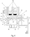
- FIG. 4 is a sectional view through the frame section 5 of FIG. 2 shown, in which between the heat-insulating strip 7 and the filling element 3, a blocking element 6 is provided.
- the filling element 3 is formed as insulating glass and has three glass plates 30 which are held by spacers 31 from each other at a distance. Furthermore, the insulating glass pane is held on the metal shell 54 via a seal 17, wherein a glass holder for fixing the insulating glass pane is provided on the frame profile 5 on the opposite side.
- the Verklotzungselement 6 is disposed on an end face of the filling element 3 and compresses the heat-insulating strip 7, which is deformed.
- the heat-insulating strip 7 is arranged between the blocking element 6 and a planar contact surface of an insulating web 52 ', wherein it can be seen that the ribs 9 and 10 are significantly shorter and, moreover, the middle web 8 is bent into the region of the receptacles 11 and 12 ,
- the height of the insulating strip 7 in the compressed position is approximately between 30% and 60% of the height in the uncompressed state, which in FIG. 2 is shown.
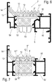
- FIG. 5 is opposite FIG. 2 shown modified embodiment, wherein the frame profile 5 is formed identical.
- the heat-insulating strip is modified only in the region of the second ribs 9 ', which are no longer tapered, but widen in the direction of the frame profile 5.
- the middle web 8 bends to the receptacles 11 'between the ribs 9' to the frame section 5 out.
- FIG. 6 a further embodiment of a modified heat-insulating strip 7 ", which is mounted on a frame profile 5.
- the heat-insulating strip 7" is as in FIG. 2 and FIG. 5 formed, except for the ribs 9 ", which face the frame profile 5.
- the ribs 9" are rectangular in cross-section and also the receptacles 11 "between the ribs 9" are also cuboidal.
- FIG. 7 a further embodiment of a heat-insulating strip is shown, in which the number of ribs 10 has been reduced on the side facing the filling element 3 side. Instead of seven ribs 10 four ribs 10 are still provided, wherein the number of ribs 10 can be modified depending on the length of the web 8 and the respective application. On the opposite side a smaller number of cuboid ribs 9 "is also provided, wherein in a receptacle 11" two webs 58 a Groove on the insulating web 52 'is arranged. In the region of the web 58, the width of the central web 8 is also reduced.
- the shape of the heat-insulating strip 7 can be varied within wide ranges in order to be adapted to the shape of the frame profile 5.
- the number of ribs 9 and 10 can be modified.
- the frame profiles shown can be assembled into a frame, wherein Verklotzungsetti 6 can be mounted on the heat-insulating strip 7, which then serve as a spacer between the heat-insulating strip 7 and the underlying frame profile 5 on the one hand and the filling element 3 on the other.
Description
- Die vorliegende Erfindung betrifft eine Wärmedämmleiste zum Einfügen in einen Spalt zwischen einem Rahmenprofil eines Fensters, einer Tür, einer Fassade oder eines Lichtdaches, und einem an dem Rahmenprofil gehaltenen Füllungselements nach dem Oberbegriff des Anspruches 1.
- Die
DE 20 2005 004 338 U1 offenbart eine Wärmedämmleiste für einen Glasfalz, bei der sich ein Grundschenkel der Wärmedämmleiste senkrecht zur Ebene der Isolierglasscheibe erstreckt und mit einem Winkelschenkel versehen ist. An dem Grundschenkel sind hervorstehende Rippen ausgebildet und Grundschenkel und Winkelschenkel sind an dem Rahmenprofil gehalten. Bei der Montage einer solchen Wärmedämmleiste müssen in regelmäßigen Abständen Verklotzungselemente zwischen Rahmenprofil und Isolierglasscheibe vorgesehen werden, sodass die Wärmedämmleiste auf die Länge des Abstandes zwischen zwei Verklotzungselementen zurecht geschnitten werden muss. Da meist an jeder Seite der Isolierglasscheibe Verklotzungselemente vorgesehen werden, ist die Montage der Wärmedämmleiste aufwändig. Zudem muss der Spalt zwischen einer Stirnseite der Isolierglasscheibe und dem Rahmenprofil vergleichsweise genau bemessen sein, um eine hohe Wärmedämmung zu erreichen. - Die
EP 1 293 639 offenbart einen einbruchhemmenden Rahmen, bei dem ein Füllungselement randseitig zwischen Dichtleisten gehalten ist. Stirnseite ist das Füllungselement zumindest bereichsweise über ein Einlegeprofil am Rahmen abgestützt, so dass ein Spalt zwischen Rahmen und Füllungselement in Form einer druckfesten Hinterfüllung geschlossen ist. DieEP1 988 247 offenbart eine Wärmedämmleiste gemäß dem Oberbegriff des Anspruchs. - Die
DE 10 2006 061 655 offenbart eine Wärmedämmleiste, die einen mittleren Steg aufweist, der sich senkrecht zur Ebene der Isolierglasscheibe erstreckt. Beidseitig des Steges können hervorstehende Rippen vorgesehen sein, die einzelne Kammern zwischen sich ausbilden. Auch hier muss der Abstand zwischen der Stirnseite der Isolierglasscheibe und dem Rahmenprofil vergleichsweise genau eingestellt werden und es besteht das Problem, dass die Länge der Wärmedämmleiste auf den Abstand zweier benachbarter Verklotzungselemente angepasst werden muss. - Es ist daher Aufgabe der vorliegenden Erfindung eine Wärmedämmleiste zum Einfügen in einen Spalt zwischen einem Rahmenprofil eines Fensters, einer Tür, einer Fassade oder eines Lichtdaches und einem an dem Rahmenprofil gehaltenen Füllungselement zu schaffen, die leicht zu montieren ist und für eine hohe Wärmedämmung sorgt.
- Diese Aufgabe wird mit einer Wärmedämmleiste mit den Merkmalen des Anspruches 1 sowie mit einem Rahmenprofil mit den Merkmalen des Anspruches 6 gelöst.
- Erfindungsgemäß weist die Wärmedämmleiste einen mittleren Steg auf, auf dem erste Rippen auf der zum Rahmenprofil und zweite Rippen auf der gegenüberliegenden Seite angeformt sind, wobei die ersten Rippen in Längsrichtung des Steges zu den zweiten Rippen versetzt angeordnet sind. Dadurch hält die Wärmedämmleiste eine besonders hohe Elastizität in eine Richtung senkrecht zur Längsrichtung des Steges in der Ebene des Füllungselementes, sodass die Rippen zwischen dem Füllungselement und dem Rahmenprofil auch anliegen können, sodass auch große Spaltabstände zwischen dem Füllungselement und dem Rahmenprofil überbrückt werden können. Zudem ermöglicht die große Biegbarkeit der Wärmedämmleiste die Montage von Verklotzungselementen auf der Wärmedämmleiste, sodass das Aussparen der Wärmedämmleiste für den Einbau der Verklotzungselemente entfallen kann. Die Verklotzungselemente können direkt auf die Wärmedämmleiste aufgelegt werden, wobei das Verklotzungselement für eine positionsgenaue Ausrichtung des Füllungselementes an dem Rahmenprofil verrastet werden kann, und in dem Bereich des Verklotzungselementes die Wärmedämmleiste komprimiert wird. Dies erspart bei der Montage das Zurechtschneiden der Wärmedämmleiste.
- Erfindungsgemäß ist zwischen zwei Rippen an der Wärmedämmleiste jeweils eine Aufnahme gebildet, wobei die Aufnahme breiter ist als eine Rippe auf der gegenüberliegenden Seite des Steges. Dadurch verformt sich der Steg beim Komprimieren bogenförmig in die Aufnahme hinein, sodass eine besonders hohe Elastizität gegeben ist. Der mittlere Steg kann dabei aus demselben elastischen Material wie die Rippen ausgebildet sein, insbesondere aus einem geschäumten Kunststoffmaterial.
- Die Rippen können ausgehend von dem Steg nach außen hin zumindest bereichsweise spitz zulaufen. Es ist auch möglich, dass die ersten Rippen auf die zum Rahmenprofil gewandte Seite breiter werden oder quaderförmig ausgebildet sind, um eine größere Anlagefläche an dem Rahmenprofil zu erhalten. Vorzugsweise ist die Länge der ersten und der zweiten Rippen im Wesentlichen gleich, die Länge sollte sich in einer bevorzugten Ausgestaltung um maximal 25 %, insbesondere um maximal 15 % unterscheiden.
- Erfindungsgemäß wird auch ein Rahmenprofil für ein Fenster, eine Tür, eine Fassade oder ein Lichtdach mit einem an dem Rahmenprofil gehaltenen Füllungselement bereitgestellt, bei dem an mindestens einer Seite des Füllungselementes ein Verklotzungselement als Abstandshalter zwischen einer Wärmedämmleiste und einer Stirnseite des Füllungselementes angeordnet ist. Die Wärmedämmleiste ist dann zwischen dem Verklotzungselement und dem Rahmenprofil angeordnet, sodass im Bereich des Verklotzungselementes die Wärmedämmleiste nicht ausgespart ist. Dies erleichtert die Montage und erhöht zudem die Wärmedämmung, da die Wärmedämmleiste eine höhere Wärmedämmung bietet wie ein Verklotzungselement. Das Verklotzungselement kann die Wärmedämmleiste komprimieren und beispielsweise im Bereich des Rahmenprofils verrastet sein.
- Gemäß einer bevorzugten Ausgestaltung ist an jeder Stirnseite des Füllungselementes mindestens ein Verklotzungselement als Abstandshalter zwischen der Wärmedämmleiste und der Stirnseite des Füllungselementes vorgesehen. Dann kann die Wärmedämmleiste in vier Abschnitte, ein Abschnitt für jede Seite, oder vollständig umlaufend an dem Rahmen montiert werden.
- Die Erfindung wird nachfolgend anhand mehrerer Ausführungsbeispiele mit Bezug auf die beigefügten Zeichnungen näher erläutert. Es zeigen:
- Figur 1
- eine schematische Ansicht eines Rahmens mit einem erfindungsgemäßen Rahmenprofil mit einer Wärmedämmleiste;
- Figur 2
- eine Schnittansicht durch ein Rahmenprofil der
Figur 1 ; - Figur 3
- eine perspektivische Ansicht durch ein Rahmenprofil im Bereich des Verklotzungselementes;
- Figur 4
- eine Schnittansicht durch das Rahmenprofil im Bereich des Verklotzungselementes in einer montierten Position;
- Figur 5
- eine Schnittansicht durch ein Rahmenprofil mit einer modifizierten Wärmedämmleiste;
- Figur 6
- eine Schnittansicht durch ein Rahmenprofil mit einer modifizierten Wärmedämmleiste;
- Figur 7
- eine Schnittansicht durch ein Rahmenprofil mit einer modifizierten Wärmedämmleiste.
-
Figur 1 zeigt ein Fenster 1 mit einem Rahmen 2, in dem als Füllungselement 3 eine Isolierglasscheibe 3 angeordnet ist. Der Rahmen 2, kann auch bei einer Tür, einer Fassade oder einem Lichtdach eingesetzt werden. Der Rahmen 2 weist zwei vertikale Rahmenprofile 4 und zwei horizontale Rahmenprofile 5 auf, die an Gehrungsflächen miteinander verbunden sind und den gleichen Querschnitt aufweisen. In einem stirnseitigen Spalt zwischen dem Füllungselement 3 und dem Rahmenprofil 5 sind umlaufend mehrere Verklotzungselemente 6 schematisch dargestellt, mittels dem die Position des Füllungselementes 3 innerhalb des Rahmens 2 ausgerichtet werden kann. Ferner ist in dem Spalt zwischen Füllungselement 3 und Rahmen 2 schematisch eine Wärmedämmleiste 7 dargestellt. - In
Figur 2 ist ein Schnitt durch ein Rahmenprofil 5 dargestellt, das als Verbundprofil ausgebildet ist und eine erste Metallschale 50 sowie eine zweite Metallschale 54 aufweist, die über Isolierstege 51 und 52 miteinander verbunden sind. Zwischen den Isolierstegen 51 und 52 ist ein Wärmedämmblock 53 angeordnet. Bezogen auf das Füllungselement 3 ist an der Innenseite des Rahmenprofils 5 die Wärmedämmleiste 7 angeordnet, die aus einem Wärmedämmmaterial, insbesondere einem geschäumten Kunststoffmaterial hergestellt ist. Die Wärmedämmleiste 7 und den mittleren Steg 8, der im Schnitt gesehen senkrecht zur Ebene des Füllungselementes 3 angeordnet ist. An dem mittleren Steg 8 sind erste Rippen 9 auf der zu dem Rahmenprofil 5 gewandten Seite angeformt und auf der gegenüberliegenden Seite sind zweite Rippen 10 dem Füllungselement 3 zugewandt. Zwischen den ersten Rippen 9 sind Aufnahmen 11 und zwischen dem Rippen 10 sind Aufnahmen 12 gebildet. Die Aufnahmen 11 und 12 sind jeweils breiter als eine Rippe 9 bzw. 10 auf der gegenüberliegenden Seite. Ferner sind die Rippen 9 und 10 versetzt zu einander angeordnet, sodass in einem Bereich des Mittelsteges 8 immer nur auf einer Seite eine Rippe 9 oder 10 vorhanden ist. - Die Wärmedämmleiste 7 umfasst ferner innenseitig einen Winkelsteg 13, der sich an dem Mittelsteg 8 anschließt und innenseitig mit einem Raststeg 14 versehen ist, der in eine Nut 55 an der Metallschale 54 des Rahmenprofils 5 eingreift. Auf der gegenüberliegenden Seite ist an dem mittleren Steg 8 ein Raststeg 15 angeformt, der in eine Nut 56 an der gegenüberliegenden Metallschale 50 des Rahmenprofils 5 eingreift, sodass die Wärmedämmleiste 7 rastend an dem Rahmenprofil 5 festgelegt werden kann.
- Aufgrund der versetzten Anordnung der Rippen 9 und 10 sind die Wärmedämmleiste 7 im Bereich der Rippen 9 und 10 in eine Richtung in der Ebene des Füllungselementes und senkrecht zu dem Steg 8 besonders biegbar ausgebildet.
- In
Figur 3 ist ein Verklotzungselement 6 an einem Rahmenprofil 5' angeordnet, das in einigen Details gegenüber dem Rahmenprofil 5 modifiziert ist, aber auch baugleich zu dem Rahmenprofil 5 ausgebildet sein kann. Das Rahmenprofil 5' ist als Verbundprofil mit einer ersten Metallschale 50 einer zweiten Metallschale 54 sowie Isolierstegen 51' und 52' ausgebildet, zwischen den ein Wärmedämmblock 53' angeordnet ist. Die an dem Rahmenprofil 5' gehaltene Wärmedämmleiste 7' umfasst einen Winkelsteg 13 sitzt aber ebenfalls einem mittleren Steg 8', von dem sich zu dem Rahmenprofil 5' erste Rippen 9 und auf der gegenüberliegenden Seite zweite Rippen 10 erstrecken. An der Wärmedämmleiste 7' ist ein Verklotzungselement 6 angeordnet, das die Wärmedämmleiste 7 fixiert und das als Abstandshalter zwischen dem Rahmenprofil 5 und dem Füllungselement 3 bei der Montage dient. Zwischen dem Verklotzungselement 6 und Rahmenprofil 5 ist die Wärmedämmleiste 7' angeordnet. - In
Figur 4 ist eine Schnittansicht durch das Rahmenprofil 5 derFigur 2 gezeigt, bei dem zwischen der Wärmedämmleiste 7 und dem Füllungselement 3 ein Verklotzungselement 6 vorgesehen ist. Das Füllungselement 3 ist als Isolierglasscheibe ausgebildet und weist drei Glasscheiben 30 auf, die über Abstandshalter 31 voneinander auf Abstand gehalten sind. Ferner ist die Isolierglasscheibe über eine Dichtung 17 an der Metallschale 54 gehalten, wobei an dem Rahmenprofil 5 auf der gegenüberliegenden Seite ein Glashalter zur Fixierung der Isolierglasscheibe vorgesehen wird. WieFigur 4 zeigt, ist das Verklotzungselement 6 an einer Stirnseite des Füllungselementes 3 angeordnet und komprimiert die Wärmedämmleiste 7, die verformt wird. Die Wärmedämmleiste 7 ist zwischen dem Verklotzungselement 6 und einer ebenen Anlagefläche eines Isoliersteges 52' angeordnet, wobei zu sehen ist, dass die Rippen 9 und 10 deutlich kürzer ausgebildet sind und zudem der mittlere Steg 8 in den Bereich der Aufnahmen 11 und 12 hinein gebogen ist. Die Höhe der Wärmedämmleiste 7 beträgt in der komprimierten Position etwa zwischen 30 % und 60 % der Höhe im unkomprimierten Zustand, der inFigur 2 gezeigt ist. - In
Figur 5 ist ein gegenüberFigur 2 modifiziertes Ausführungsbeispiel gezeigt, wobei das Rahmenprofil 5 identisch ausgebildet ist. Die Wärmedämmleiste ist nur im Bereich der zweiten Rippen 9' modifiziert, die nicht mehr spitz zulaufend ausgebildet sind, sondern sich in Richtung des Rahmenprofils 5 verbreitern. Dadurch wird eine größere Anlagefläche zwischen Wärmedämmleiste 7 und dem Rahmenprofil 5 erhalten. Der mittlere Steg 8 biegt sich an den Aufnahmen 11' zwischen den Rippen 9' zum Rahmenprofil 5 hin. - In
Figur 6 ist ein weiteres Ausführungsbeispiel einer modifizierten Wärmedämmleiste 7" gezeigt, die an einem Rahmenprofil 5 montiert ist. Die Wärmedämmleiste 7" ist wie inFigur 2 undFigur 5 ausgebildet, bis auf die Rippen 9", die dem Rahmenprofil 5 zugewandt sind. Die Rippen 9" sind im Querschnitt quaderförmig ausgebildet und auch die Aufnahmen 11" zwischen den Rippen 9" sind ebenfalls quaderförmig. - In
Figur 7 ist ein weiteres Ausführungsbeispiel einer Wärmedämmleiste gezeigt, bei der die Anzahl der Rippen 10 auf der zum Füllungselement 3 gewandten Seite reduziert wurde. Statt sieben Rippen 10 sind noch vier Rippen 10 vorgesehen, wobei die Anzahl der Rippen 10 abhängig von der Länge des Steges 8 und dem jeweiligen Einsatzzweck modifiziert werden kann. Auf der gegenüberliegenden Seite ist ebenfalls eine geringere Anzahl von quaderförmigen Rippen 9" vorgesehen, wobei in einer Aufnahme 11" zwei Stege 58 einer Nut an dem Isoliersteg 52' angeordnet ist. Im Bereich des Stegs 58 ist die Breite des Mittelsteges 8 ebenfalls reduziert. - Die Form der Wärmedämmleiste 7 kann in weiten Bereichen variiert werden, um an die Form des Rahmenprofils 5 angepasst zu werden. Zudem kann die Anzahl der Rippen 9 und 10 modifiziert werden.
- Die gezeigten Rahmenprofile können zu einem Rahmen zusammengesetzt werden, wobei Verklotzungselemente 6 auf die Wärmedämmleiste 7 montiert werden können, die dann als Abstandshalter zwischen der Wärmedämmleiste 7 und dem darunter liegenden Rahmenprofil 5 einerseits und dem Füllungselement 3 andererseits dienen.
-
- 1
- Fenster
- 2
- Rahmen
- 3
- Füllungselement
- 4
- vertikale Rahmenprofile
- 5
- horizontale Rahmenprofile
- 5'
- horizontale Rahmenprofile
- 6
- Verklotzungselement
- 7
- Wärmedämmleiste
- 7'
- Wärmedämmleiste
- 7"
- Wärmedämmleiste
- 8
- Steg
- 8'
- Steg
- 9
- erste Rippen
- 9'
- erste Rippen
- 9"
- erste Rippen
- 10
- zweite Rippen
- 11
- Aufnahme
- 11'
- Aufnahme
- 11"
- Aufnahme
- 12
- Aufnahme
- 13
- Winkelsteg
- 14
- Raststeg
- 17
- Dichtung
- 30
- Glasscheiben
- 31
- Abstandshalter
- 50
- erste Metallschale
- 51
- Isoliersteg
- 51'
- Isoliersteg
- 52
- Isoliersteg
- 52'
- Isoliersteg
- 53
- Wärmedämmblock
- 53'
- Wärmedämmblock
- 54
- zweite Metallschale
- 55
- Nut
- 56
- Nut
- 58
- Stege
Claims (9)
- Wärmedämmleiste (7) zum Einfügen in einen Spalt zwischen einem Rahmenprofil (5) eines Fensters, einer Tür, einer Fassade oder eines Lichtdaches, und ein an dem Rahmenprofil (5) gehaltenen Füllungselementen (3), mit einem mittleren Steg (8), an dem auf einer zu dem Rahmenprofil gewandten Seite erste Rippen (9, 9', 9") angeformt sind und an dem auf einer zu den Füllungselementen (3) gewandten Seite zweite Rippen (10) angeformt sind, wobei die ersten Rippen (9, 9', 9") in Längsrichtung des Steges (8) zu den zweiten Rippen (10) versetzt angeordnet sind und zwischen zwei Rippen (9, 9', 9", 10) jeweils eine Aufnahme (11, 12) ausgebildet ist und die Aufnahme (11, 12) breiter ist als eine Rippe (9, 9', 9", 10) auf der gegenüberliegenden Seite des Steges (8), dadurch gekennzeichnet, dass der Steg (8) beim Komprimieren der Wärmedämmleiste zwischen dem Rahmenprofil und dem Füllungselement bogenförmig in jede Aufnahme (11, 12) hinein verformt ist.
- Wärmedämmleiste nach Anspruch 1, dadurch gekennzeichnet, dass der mittlere Steg (8) in eine Richtung senkrecht zur Längsrichtung des Steges (8) und in der Ebene des Füllungselementes (3) biegbar ausgerichtet ist.
- Wärmedämmleiste nach Anspruch 1 oder 2, dadurch gekennzeichnet, dass die Rippen (9, 10) zumindest teilweise nach außen spitz zulaufen.
- Wärmedämmleiste nach einem der vorhergehenden Ansprüche, dadurch gekennzeichnet, dass die ersten Rippen (9, 9', 9") auf der zum Rahmenprofil (5) gewandte Seite breiter werden oder quaderförmig ausgebildet sind.
- Wärmedämmleiste nach einem der vorhergehenden Ansprüche, dadurch gekennzeichnet, dass die Länge der ersten Rippen (9, 9', 9") und der zweiten Rippen (10) maximal um 25 %, insbesondere maximal um 15 % unterschiedlich sind.
- Rahmenprofil (5) für ein Fenster, eine Tür, eine Fassade oder ein Lichtdach mit einem an dem Rahmenprofil (5) gehaltenen Füllungselementen (3), dadurch gekennzeichnet, dass an mindestens einer Seite des Füllungselementes (3) ein Verklotzungselement (6) als Abstandshalter zwischen einer Wärmedämmleiste (7) nach einem der vorhergehenden Ansprüche und einer Stirnseite des Füllungselementes (3) angeordnet ist.
- Rahmenprofil nach Anspruch 6, dadurch gekennzeichnet, dass an jeder Stirnseite des Füllungselementes (3) mindestens ein Verklotzungselement (6) als Abstandshalter zwischen der Wärmedämmleiste (7) und einer Stirnseite des Füllungselementes (3) vorgesehen ist.
- Rahmenprofil nach Anspruch 6 oder 7, dadurch gekennzeichnet, dass in einem Spalt zwischen dem Rahmenprofil (5) und dem Füllungselement (3) mindestens eine Wärmedämmleiste (7) nach einem der vorhergehenden Ansprüche angeordnet ist.
- Fenster, Tür, Fassade oder Lichtdach mit einem Rahmenprofil nach einem der Ansprüche 6 bis 8.
Applications Claiming Priority (1)
| Application Number | Priority Date | Filing Date | Title |
|---|---|---|---|
| DE201320100101 DE202013100101U1 (de) | 2013-01-10 | 2013-01-10 | Wärmedämmleiste und Rahmenprofil für ein Fenster, eine Tür, eine Fassade oder ein Lichtdach |
Publications (2)
| Publication Number | Publication Date |
|---|---|
| EP2754834A1 EP2754834A1 (de) | 2014-07-16 |
| EP2754834B1 true EP2754834B1 (de) | 2017-07-05 |
Family
ID=47991195
Family Applications (1)
| Application Number | Title | Priority Date | Filing Date |
|---|---|---|---|
| EP13195637.7A Active EP2754834B1 (de) | 2013-01-10 | 2013-12-04 | Wärmedämmleiste und Rahmenprofil für ein Fenster, eine Tür, eine Fassade oder ein Lichtdach |
Country Status (2)
| Country | Link |
|---|---|
| EP (1) | EP2754834B1 (de) |
| DE (1) | DE202013100101U1 (de) |
Families Citing this family (3)
| Publication number | Priority date | Publication date | Assignee | Title |
|---|---|---|---|---|
| BE1021797B1 (nl) | 2013-12-20 | 2016-01-19 | BLYWEERT ALUMINIUM, naamloze vennootschap | Kunststof isolatiesteeg, samengesteld profiel en raam die een dergelijke isolatiesteeg omvatten en werkwijze om een kader voor een raam te veraardigen |
| DE102016125922A1 (de) * | 2016-12-30 | 2018-07-05 | SCHÜCO International KG | Fenster oder Tür mit einem Flügelrahmen mit einem Glasträger |
| FR3073247B1 (fr) * | 2017-11-06 | 2021-10-29 | Daniel Kamennoff | Lamelles de coupure thermique extrudees pour vitrage |
Citations (1)
| Publication number | Priority date | Publication date | Assignee | Title |
|---|---|---|---|---|
| EP1988247A2 (de) * | 2007-05-04 | 2008-11-05 | Norsk Hydro ASA | Rahmen, insbesondere für Öffnungsflügel oder Zarge eines Fensters oder einer Tür und Verfahren zum Einsetzen eines Paneels in diesen Rahmen |
Family Cites Families (3)
| Publication number | Priority date | Publication date | Assignee | Title |
|---|---|---|---|---|
| DE10145616A1 (de) * | 2001-09-15 | 2003-04-17 | Wicona Bausysteme Gmbh | Einbruchhemmender Rahmen |
| DE202005004338U1 (de) | 2005-03-17 | 2005-05-25 | SCHÜCO International KG | Wärmedämmleiste für einen Glasfalz |
| DE102006061655A1 (de) | 2006-10-13 | 2008-04-17 | Raico Bautechnik Gmbh | Wärmedämmleiste |
-
2013
- 2013-01-10 DE DE201320100101 patent/DE202013100101U1/de not_active Expired - Lifetime
- 2013-12-04 EP EP13195637.7A patent/EP2754834B1/de active Active
Patent Citations (1)
| Publication number | Priority date | Publication date | Assignee | Title |
|---|---|---|---|---|
| EP1988247A2 (de) * | 2007-05-04 | 2008-11-05 | Norsk Hydro ASA | Rahmen, insbesondere für Öffnungsflügel oder Zarge eines Fensters oder einer Tür und Verfahren zum Einsetzen eines Paneels in diesen Rahmen |
Also Published As
| Publication number | Publication date |
|---|---|
| EP2754834A1 (de) | 2014-07-16 |
| DE202013100101U1 (de) | 2013-02-22 |
Similar Documents
| Publication | Publication Date | Title |
|---|---|---|
| EP3155187B1 (de) | Wärmeisolierendes abstandhalterprofil | |
| DE112013003263B4 (de) | Steckverbinder und Steckverbindung | |
| EP2576949B1 (de) | Thermisch getrenntes profil | |
| DE10033388A1 (de) | Wärmegedämmtes Verbundprofil, insbesondere für Fenster, Türen, Fassaden und dergleichen | |
| EP2666948A1 (de) | Rahmenanordnung für ein Sektionaltorpaneel | |
| EP2754834B1 (de) | Wärmedämmleiste und Rahmenprofil für ein Fenster, eine Tür, eine Fassade oder ein Lichtdach | |
| DE10223038B4 (de) | Fassadenkonstruktion mit einem durch ein Dichtelement abgedichteten riegelseitigen Isolierprofil | |
| EP2307629B1 (de) | Trennwand aus transparenten wandelementen | |
| AT392311B (de) | Rahmenkonstruktion in pfosten-riegel-bauweise, insbesondere fuer fassaden, daecher, fensterwaende od. dgl. | |
| DE202013105916U1 (de) | Fenster- oder Türflügel mit einer Haltevorrichtung zur Aufnahme eines flügelüberdeckenden Flächenelements | |
| EP2497888B1 (de) | Wärmegedämmtes Verbundprofil | |
| EP1437478B1 (de) | Wärmegedämmtes Verbundprofil | |
| EP4087984B1 (de) | System und verfahren zum errichten von gebäudewänden, -decken und/oder -dächern | |
| EP2754839B1 (de) | Rahmen oder T-Verbindung und Verfahren zur Montage eines Rahmens oder einer T-Verbindung | |
| AT500953A2 (de) | Halte- und dichtungssystem für rahmenlose isolierglaselemente | |
| DE10028802A1 (de) | Bauelement und Verwendung eines Trägers sowie Verfahren zur Herstellung eines Fassadenelementes | |
| DE202009013708U1 (de) | Fassade | |
| EP2123838B1 (de) | Fassadenplattentragkonstruktion | |
| EP2573307A1 (de) | Mehrteiliges Profilrahmensytem für Türen, Tore, Wintergärten und Fenster | |
| EP2431561B1 (de) | Structural-Glazing-Konstruktion | |
| EP3667009A1 (de) | Fenster und verfahren zur montage eines fensters | |
| DE102012025362B4 (de) | Firstprofilelement für ein Satteldach und Verfahren zum Montieren eines Satteldachs | |
| DE102020103737A1 (de) | Blend- und/oder Flügelrahmen für ein Brandschutzfenster, eine Brandschutztür und/oder eine Brandschutzfassade | |
| DE102020101068A1 (de) | Verbundprofil, Rahmen und Elementfassade | |
| EP1857605A1 (de) | Bodenabdeckung für ein Gebäudeteil |
Legal Events
| Date | Code | Title | Description |
|---|---|---|---|
| PUAI | Public reference made under article 153(3) epc to a published international application that has entered the european phase |
Free format text: ORIGINAL CODE: 0009012 |
|
| 17P | Request for examination filed |
Effective date: 20131204 |
|
| AK | Designated contracting states |
Kind code of ref document: A1 Designated state(s): AL AT BE BG CH CY CZ DE DK EE ES FI FR GB GR HR HU IE IS IT LI LT LU LV MC MK MT NL NO PL PT RO RS SE SI SK SM TR |
|
| AX | Request for extension of the european patent |
Extension state: BA ME |
|
| R17P | Request for examination filed (corrected) |
Effective date: 20141218 |
|
| RBV | Designated contracting states (corrected) |
Designated state(s): AL AT BE BG CH CY CZ DE DK EE ES FI FR GB GR HR HU IE IS IT LI LT LU LV MC MK MT NL NO PL PT RO RS SE SI SK SM TR |
|
| 17Q | First examination report despatched |
Effective date: 20160418 |
|
| GRAP | Despatch of communication of intention to grant a patent |
Free format text: ORIGINAL CODE: EPIDOSNIGR1 |
|
| INTG | Intention to grant announced |
Effective date: 20170216 |
|
| GRAS | Grant fee paid |
Free format text: ORIGINAL CODE: EPIDOSNIGR3 |
|
| GRAA | (expected) grant |
Free format text: ORIGINAL CODE: 0009210 |
|
| AK | Designated contracting states |
Kind code of ref document: B1 Designated state(s): AL AT BE BG CH CY CZ DE DK EE ES FI FR GB GR HR HU IE IS IT LI LT LU LV MC MK MT NL NO PL PT RO RS SE SI SK SM TR |
|
| REG | Reference to a national code |
Ref country code: GB Ref legal event code: FG4D Free format text: NOT ENGLISH |
|
| REG | Reference to a national code |
Ref country code: CH Ref legal event code: EP |
|
| REG | Reference to a national code |
Ref country code: AT Ref legal event code: REF Ref document number: 906732 Country of ref document: AT Kind code of ref document: T Effective date: 20170715 |
|
| REG | Reference to a national code |
Ref country code: IE Ref legal event code: FG4D Free format text: LANGUAGE OF EP DOCUMENT: GERMAN |
|
| REG | Reference to a national code |
Ref country code: DE Ref legal event code: R096 Ref document number: 502013007682 Country of ref document: DE |
|
| REG | Reference to a national code |
Ref country code: NL Ref legal event code: MP Effective date: 20170705 |
|
| REG | Reference to a national code |
Ref country code: LT Ref legal event code: MG4D |
|
| PG25 | Lapsed in a contracting state [announced via postgrant information from national office to epo] |
Ref country code: LT Free format text: LAPSE BECAUSE OF FAILURE TO SUBMIT A TRANSLATION OF THE DESCRIPTION OR TO PAY THE FEE WITHIN THE PRESCRIBED TIME-LIMIT Effective date: 20170705 Ref country code: NO Free format text: LAPSE BECAUSE OF FAILURE TO SUBMIT A TRANSLATION OF THE DESCRIPTION OR TO PAY THE FEE WITHIN THE PRESCRIBED TIME-LIMIT Effective date: 20171005 Ref country code: SE Free format text: LAPSE BECAUSE OF FAILURE TO SUBMIT A TRANSLATION OF THE DESCRIPTION OR TO PAY THE FEE WITHIN THE PRESCRIBED TIME-LIMIT Effective date: 20170705 Ref country code: NL Free format text: LAPSE BECAUSE OF FAILURE TO SUBMIT A TRANSLATION OF THE DESCRIPTION OR TO PAY THE FEE WITHIN THE PRESCRIBED TIME-LIMIT Effective date: 20170705 Ref country code: HR Free format text: LAPSE BECAUSE OF FAILURE TO SUBMIT A TRANSLATION OF THE DESCRIPTION OR TO PAY THE FEE WITHIN THE PRESCRIBED TIME-LIMIT Effective date: 20170705 Ref country code: FI Free format text: LAPSE BECAUSE OF FAILURE TO SUBMIT A TRANSLATION OF THE DESCRIPTION OR TO PAY THE FEE WITHIN THE PRESCRIBED TIME-LIMIT Effective date: 20170705 |
|
| PG25 | Lapsed in a contracting state [announced via postgrant information from national office to epo] |
Ref country code: PL Free format text: LAPSE BECAUSE OF FAILURE TO SUBMIT A TRANSLATION OF THE DESCRIPTION OR TO PAY THE FEE WITHIN THE PRESCRIBED TIME-LIMIT Effective date: 20170705 Ref country code: GR Free format text: LAPSE BECAUSE OF FAILURE TO SUBMIT A TRANSLATION OF THE DESCRIPTION OR TO PAY THE FEE WITHIN THE PRESCRIBED TIME-LIMIT Effective date: 20171006 Ref country code: RS Free format text: LAPSE BECAUSE OF FAILURE TO SUBMIT A TRANSLATION OF THE DESCRIPTION OR TO PAY THE FEE WITHIN THE PRESCRIBED TIME-LIMIT Effective date: 20170705 Ref country code: IS Free format text: LAPSE BECAUSE OF FAILURE TO SUBMIT A TRANSLATION OF THE DESCRIPTION OR TO PAY THE FEE WITHIN THE PRESCRIBED TIME-LIMIT Effective date: 20171105 Ref country code: BG Free format text: LAPSE BECAUSE OF FAILURE TO SUBMIT A TRANSLATION OF THE DESCRIPTION OR TO PAY THE FEE WITHIN THE PRESCRIBED TIME-LIMIT Effective date: 20171005 Ref country code: LV Free format text: LAPSE BECAUSE OF FAILURE TO SUBMIT A TRANSLATION OF THE DESCRIPTION OR TO PAY THE FEE WITHIN THE PRESCRIBED TIME-LIMIT Effective date: 20170705 Ref country code: ES Free format text: LAPSE BECAUSE OF FAILURE TO SUBMIT A TRANSLATION OF THE DESCRIPTION OR TO PAY THE FEE WITHIN THE PRESCRIBED TIME-LIMIT Effective date: 20170705 |
|
| REG | Reference to a national code |
Ref country code: DE Ref legal event code: R097 Ref document number: 502013007682 Country of ref document: DE |
|
| PG25 | Lapsed in a contracting state [announced via postgrant information from national office to epo] |
Ref country code: RO Free format text: LAPSE BECAUSE OF FAILURE TO SUBMIT A TRANSLATION OF THE DESCRIPTION OR TO PAY THE FEE WITHIN THE PRESCRIBED TIME-LIMIT Effective date: 20170705 Ref country code: DK Free format text: LAPSE BECAUSE OF FAILURE TO SUBMIT A TRANSLATION OF THE DESCRIPTION OR TO PAY THE FEE WITHIN THE PRESCRIBED TIME-LIMIT Effective date: 20170705 Ref country code: CZ Free format text: LAPSE BECAUSE OF FAILURE TO SUBMIT A TRANSLATION OF THE DESCRIPTION OR TO PAY THE FEE WITHIN THE PRESCRIBED TIME-LIMIT Effective date: 20170705 |
|
| PLBE | No opposition filed within time limit |
Free format text: ORIGINAL CODE: 0009261 |
|
| STAA | Information on the status of an ep patent application or granted ep patent |
Free format text: STATUS: NO OPPOSITION FILED WITHIN TIME LIMIT |
|
| PG25 | Lapsed in a contracting state [announced via postgrant information from national office to epo] |
Ref country code: IT Free format text: LAPSE BECAUSE OF FAILURE TO SUBMIT A TRANSLATION OF THE DESCRIPTION OR TO PAY THE FEE WITHIN THE PRESCRIBED TIME-LIMIT Effective date: 20170705 Ref country code: SK Free format text: LAPSE BECAUSE OF FAILURE TO SUBMIT A TRANSLATION OF THE DESCRIPTION OR TO PAY THE FEE WITHIN THE PRESCRIBED TIME-LIMIT Effective date: 20170705 Ref country code: EE Free format text: LAPSE BECAUSE OF FAILURE TO SUBMIT A TRANSLATION OF THE DESCRIPTION OR TO PAY THE FEE WITHIN THE PRESCRIBED TIME-LIMIT Effective date: 20170705 Ref country code: SM Free format text: LAPSE BECAUSE OF FAILURE TO SUBMIT A TRANSLATION OF THE DESCRIPTION OR TO PAY THE FEE WITHIN THE PRESCRIBED TIME-LIMIT Effective date: 20170705 |
|
| 26N | No opposition filed |
Effective date: 20180406 |
|
| REG | Reference to a national code |
Ref country code: CH Ref legal event code: PL |
|
| GBPC | Gb: european patent ceased through non-payment of renewal fee |
Effective date: 20171204 |
|
| PG25 | Lapsed in a contracting state [announced via postgrant information from national office to epo] |
Ref country code: SI Free format text: LAPSE BECAUSE OF FAILURE TO SUBMIT A TRANSLATION OF THE DESCRIPTION OR TO PAY THE FEE WITHIN THE PRESCRIBED TIME-LIMIT Effective date: 20170705 |
|
| REG | Reference to a national code |
Ref country code: IE Ref legal event code: MM4A |
|
| PG25 | Lapsed in a contracting state [announced via postgrant information from national office to epo] |
Ref country code: LU Free format text: LAPSE BECAUSE OF NON-PAYMENT OF DUE FEES Effective date: 20171204 Ref country code: MT Free format text: LAPSE BECAUSE OF FAILURE TO SUBMIT A TRANSLATION OF THE DESCRIPTION OR TO PAY THE FEE WITHIN THE PRESCRIBED TIME-LIMIT Effective date: 20170705 |
|
| REG | Reference to a national code |
Ref country code: FR Ref legal event code: ST Effective date: 20180831 |
|
| REG | Reference to a national code |
Ref country code: BE Ref legal event code: MM Effective date: 20171231 |
|
| PG25 | Lapsed in a contracting state [announced via postgrant information from national office to epo] |
Ref country code: FR Free format text: LAPSE BECAUSE OF NON-PAYMENT OF DUE FEES Effective date: 20180102 Ref country code: IE Free format text: LAPSE BECAUSE OF NON-PAYMENT OF DUE FEES Effective date: 20171204 |
|
| PG25 | Lapsed in a contracting state [announced via postgrant information from national office to epo] |
Ref country code: BE Free format text: LAPSE BECAUSE OF NON-PAYMENT OF DUE FEES Effective date: 20171231 Ref country code: CH Free format text: LAPSE BECAUSE OF NON-PAYMENT OF DUE FEES Effective date: 20171231 Ref country code: LI Free format text: LAPSE BECAUSE OF NON-PAYMENT OF DUE FEES Effective date: 20171231 Ref country code: GB Free format text: LAPSE BECAUSE OF NON-PAYMENT OF DUE FEES Effective date: 20171204 |
|
| PG25 | Lapsed in a contracting state [announced via postgrant information from national office to epo] |
Ref country code: MC Free format text: LAPSE BECAUSE OF FAILURE TO SUBMIT A TRANSLATION OF THE DESCRIPTION OR TO PAY THE FEE WITHIN THE PRESCRIBED TIME-LIMIT Effective date: 20170705 Ref country code: HU Free format text: LAPSE BECAUSE OF FAILURE TO SUBMIT A TRANSLATION OF THE DESCRIPTION OR TO PAY THE FEE WITHIN THE PRESCRIBED TIME-LIMIT; INVALID AB INITIO Effective date: 20131204 |
|
| PG25 | Lapsed in a contracting state [announced via postgrant information from national office to epo] |
Ref country code: CY Free format text: LAPSE BECAUSE OF NON-PAYMENT OF DUE FEES Effective date: 20170705 |
|
| PG25 | Lapsed in a contracting state [announced via postgrant information from national office to epo] |
Ref country code: MK Free format text: LAPSE BECAUSE OF FAILURE TO SUBMIT A TRANSLATION OF THE DESCRIPTION OR TO PAY THE FEE WITHIN THE PRESCRIBED TIME-LIMIT Effective date: 20170705 |
|
| REG | Reference to a national code |
Ref country code: AT Ref legal event code: MM01 Ref document number: 906732 Country of ref document: AT Kind code of ref document: T Effective date: 20181204 |
|
| PG25 | Lapsed in a contracting state [announced via postgrant information from national office to epo] |
Ref country code: TR Free format text: LAPSE BECAUSE OF FAILURE TO SUBMIT A TRANSLATION OF THE DESCRIPTION OR TO PAY THE FEE WITHIN THE PRESCRIBED TIME-LIMIT Effective date: 20170705 |
|
| PG25 | Lapsed in a contracting state [announced via postgrant information from national office to epo] |
Ref country code: AT Free format text: LAPSE BECAUSE OF NON-PAYMENT OF DUE FEES Effective date: 20181204 |
|
| PG25 | Lapsed in a contracting state [announced via postgrant information from national office to epo] |
Ref country code: PT Free format text: LAPSE BECAUSE OF FAILURE TO SUBMIT A TRANSLATION OF THE DESCRIPTION OR TO PAY THE FEE WITHIN THE PRESCRIBED TIME-LIMIT Effective date: 20170705 |
|
| PG25 | Lapsed in a contracting state [announced via postgrant information from national office to epo] |
Ref country code: AL Free format text: LAPSE BECAUSE OF FAILURE TO SUBMIT A TRANSLATION OF THE DESCRIPTION OR TO PAY THE FEE WITHIN THE PRESCRIBED TIME-LIMIT Effective date: 20170705 |
|
| PGFP | Annual fee paid to national office [announced via postgrant information from national office to epo] |
Ref country code: DE Payment date: 20230116 Year of fee payment: 10 |
|
| P01 | Opt-out of the competence of the unified patent court (upc) registered |
Effective date: 20230813 |