EP2753435B1 - Système de rangement d'objets dans des récipients de rangement prédéterminés - Google Patents
Système de rangement d'objets dans des récipients de rangement prédéterminés Download PDFInfo
- Publication number
- EP2753435B1 EP2753435B1 EP12773019.0A EP12773019A EP2753435B1 EP 2753435 B1 EP2753435 B1 EP 2753435B1 EP 12773019 A EP12773019 A EP 12773019A EP 2753435 B1 EP2753435 B1 EP 2753435B1
- Authority
- EP
- European Patent Office
- Prior art keywords
- transport
- objects
- conveyor
- camera
- storing
- Prior art date
- Legal status (The legal status is an assumption and is not a legal conclusion. Google has not performed a legal analysis and makes no representation as to the accuracy of the status listed.)
- Not-in-force
Links
Images

Classifications
-
- B—PERFORMING OPERATIONS; TRANSPORTING
- B07—SEPARATING SOLIDS FROM SOLIDS; SORTING
- B07C—POSTAL SORTING; SORTING INDIVIDUAL ARTICLES, OR BULK MATERIAL FIT TO BE SORTED PIECE-MEAL, e.g. BY PICKING
- B07C5/00—Sorting according to a characteristic or feature of the articles or material being sorted, e.g. by control effected by devices which detect or measure such characteristic or feature; Sorting by manually actuated devices, e.g. switches
- B07C5/34—Sorting according to other particular properties
- B07C5/3412—Sorting according to other particular properties according to a code applied to the object which indicates a property of the object, e.g. quality class, contents or incorrect indication
-
- B—PERFORMING OPERATIONS; TRANSPORTING
- B07—SEPARATING SOLIDS FROM SOLIDS; SORTING
- B07C—POSTAL SORTING; SORTING INDIVIDUAL ARTICLES, OR BULK MATERIAL FIT TO BE SORTED PIECE-MEAL, e.g. BY PICKING
- B07C5/00—Sorting according to a characteristic or feature of the articles or material being sorted, e.g. by control effected by devices which detect or measure such characteristic or feature; Sorting by manually actuated devices, e.g. switches
- B07C5/36—Sorting apparatus characterised by the means used for distribution
- B07C5/38—Collecting or arranging articles in groups
Definitions
- the invention relates to a system for storing objects, such as surgical instruments, in predetermined storage containers, comprising a conveyor for transporting objects placed on the conveyor to an object recognition camera by reading a code provided on these and a device for storing each object in the storage container for which it is intended (cf. WO-A-03/011484 or WO-2011/029991 ).
- the storage system be of simple structure and operation while guaranteeing perfect security, although the operation of storing in a container all the instruments that are part of a set necessary for use specific, for example for a specific surgical procedure, is a complex operation.
- the invention aims to overcome this disadvantage.
- a system according to the invention is characterized in that it comprises a device for transferring or ejecting each recognized object, the conveyor in a transport box of the object in the container for which it is intended , and a transport box support device, which is movable in step-by-step movement, each step of the transport device corresponding to a conveyor advancement step, during which the object has been recognized by the transport camera. recognition.
- the storage system is characterized in that the transport boxes are mounted on a mobile support means, made in the form of a carousel having at its periphery said transport boxes whose number is at less equal to the number of storage containers.
- the storage system is characterized in that the transport boxes are mounted on a movable support means moving linearly in a vas movement and which is at least as many steps as there has storage containers.
- the storage system is characterized in that the transport device comprises at least one more transport box than there are storage containers, this additional box being intended for unloading containers. instruments that could not be unloaded in a storage container, in a waste container.
- the storage system is characterized in that each transport box is mounted on the pivoting support between a position of receiving and transporting an object and an unloading position of an object in a storage container.
- the storage system is characterized in that it comprises, upstream of the camera of recognition by reading the codes of the objects, a camera of shooting for the positioning of the objects on the conveyor in positions allowing recognition of objects by the reconnaissance camera.
- the storage system is characterized in that the order and the number of the storage containers are determined according to the order of arrival on the transport device of the recognized objects.
- the storage system is characterized in that the storage container of the assembly of which the first recognized object is part is the container which is remote from a movement step of the transport device, the receiving position of the objects to be stored.
- the storage system is characterized in that the coordinates and the contents of the storage containers are advantageously displayed on a display screen associated with the recognition camera.
- the invention will be described by way of example in its application to a surgical instrument storage system in predetermined storage containers, so that these containers each contain a set of instruments selected for a specific use such as a surgical intervention.
- the invention is not limited to this application.
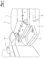
- a system according to the invention comprises a conveyor 1 made in the form of an endless belt, for the reception of the surgical instruments 3 to be stored in a storage container 4 assigned, which is intended to transport these instruments 3 from their place of installation on the conveyor to a transfer point of the conveyor, by a transfer device or ejection 5, on a device 6 of transport of the transferred instruments in their storage container.
- the transport device comprises a support means 7 made in the form of a carousel, comprising at its periphery a number of transport boxes 8, each intended to receive an instrument 3 transferred from the conveyor 1.
- the carousel moves in a stepwise motion, the boxes 8 being uniformly distributed at the periphery of the carousel.
- a support table 9 a storage container 4, in the figures in FIG. shape of a box, so that the instrument in a transport box 8 can be transferred into a storage container.
- the system comprises N-1 storage containers.
- the transport boxes 8 are mounted on the carousel, pivoting between a receiving position and transport of an instrument and a position of unloading thereof in the corresponding storage container 4.
- each of these containers 4 is intended to contain a set of surgical instruments, established for a predetermined use, for example a surgical procedure, as has been stated above.
- the system is equipped with an instrument recognition device, by means of a reconnaissance camera 12 instruments 3 by reading a specific code which is provided each instrument.
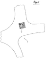
- the figure 5 shows by way of example an instrument coded by a number of coding points distributed in a unique manner for this instrument over an area, for example square, of the surface of the instrument. Of course, any other means of coding could be provided.
- the instrument recognition camera 12 hereinafter referred to as the decoding camera, is located upstream of the transfer location.
- the system according to the invention comprises another camera noted 14 which is a camera and has the function of reproducing on its display screen 15 the image of the instrument which is arranged in its field of view on the conveyor.
- This camera thus makes it possible to place the instrument on the conveyor so that the zone 16 which contains the code is in the center of the screen 15 and therefore in a position which enables the decoding camera 12 to read this code optimal when the instrument is in its field of vision.
- the surgical instruments to be stored in the storage containers 4 are arranged on the conveyor by an operator who has a console 17 for controlling the conveyor.
- each instrument After correctly placing a first instrument 3 which is named 3a to facilitate the understanding of the invention, on the conveyor 1, with the coding zone under the camera, in the field of view thereof, position that the operator can monitor by means of the screen, it presses a button on its control panel 17, which sets the conveyor in motion so that it carries the instrument to the device of transfer 5 by passing it under the decoding camera 12.
- each instrument can have on both sides, namely the face facing upwards and the face on which it rests on the conveyor , the code characterizing it.
- the instrument 3a When the instrument 3a passes under the decoding camera 12, it reads the code and recognizes, that is to say, identifies the instrument. When the instrument is in front of the transfer device, the latter moves the instrument perpendicular to the axis of the conveyor and pushes it on the inclined plane 19 which allows the instrument to slide into the transport box 8 of the carousel, who is in front of him and who is named 8a.
- the operator has placed on the conveyor in the field of view of the camera 14 a second instrument named 3b.
- this instrument is correctly positioned, that is to say its code is in the center of the image reproduced on the screen
- the operator presses the control button of his desk 17, which makes start the conveyor which then moves the instrument to the decoding camera 12 so that it can recognize, that is to say, identify the instrument, and up to the transfer device 5, on the one hand, and on the other hand rotating a step of the carousel so that the transport box 8a which had previously received the first instrument 3a is at the end of the step at the first storage container 4a.
- this instrument is discharged into the second storage container 4b at the end of the second rotation step made during the recognition of the third instrument 3c that the ejector pushed into the third transport box 8c.
- the storage container 4b then becomes the storage container of all the instruments of the assembly of which the second instrument 3b is part.
- each step of recognizing an instrument causes the rotation of a step of the carousel.
- the storage containers 4 intended to receive the different sets of instruments are determined as the recognition of the instruments by the decoding camera.
- the assembly of which the first instrument 3a is part is received in the first storage container 4a and all the instruments that form part of this set will then be unloaded into this container 4a.
- Recognition of the first instrument that is not part of the set for the storage container 4a will be placed in the second storage container 4b.
- the first recognized instrument that is part of a third set is unloaded into the third storage container 4c and on.
- composition of the storage containers and their identification number is displayed on a screen 18 of the decoding camera 12 so that the invention allows perfect traceability of the instruments.
- the decoding camera 12 could be movably mounted in the moving directions of the conveyor and perpendicular to it so that it can always be placed optimally above the coding area of each instrument, under the control of the shooting camera.
- the time that the carousel must have to perform a rotation step will then be determined by the movement of the recognized instruments, that is to say decoded, to the ejector.
- the movement of the conveyor is then triggered at the end of the recognition operation by the camera or in any other appropriate manner.
- a step of advancement of the conveyor could then ensure the movement of an instrument from its place of placing on the conveyor to the transfer device, and this step of advancement of the conveyor, will trigger the movement of advancement one step from the carousel.
- the carousel could also be replaced by a device that moves the transport boxes linearly, step by step, to unload the instruments in storage containers then properly aligned.
- the system includes in addition to storage containers a waste box for receiving instruments that could not be placed in storage containers, for various reasons. One could also consider, without departing from the scope of the invention, to determine in advance the storage containers which will then be filled according to appropriate software.
Description
- L'invention concerne un système de rangement d'objets, tels que des instruments chirurgicaux, dans des récipients de rangement prédéterminés, comprenant un convoyeur de transport des objets placés sur le convoyeur à une caméra de reconnaissance des objets par lecture d'un code prévu sur ceux-ci et un dispositif de rangement de chaque objet dans le récipient de rangement auquel il est destiné (cf.
WO-A-03/011484 WO-A-2011/029991 ). - Il est souhaitable que le système de rangement soit d'une structure et d'un fonctionnement simple tout en garantissant une sécurité parfaite, bien que l'opération de ranger dans un récipient tous les instruments qui font partie d'un ensemble nécessaires pour une utilisation spécifique, par exemple pour une intervention chirurgicale déterminée, constitue une opération complexe.
- Il s'avère que jusqu'à présent des systèmes qui satisfont aux exigences susmentionnées n'existent pas.
- Par conséquent, l'invention a pour but de pallier cet inconvénient.
- Pour atteindre ce but, un système selon l'invention est caractérisé en ce qu'il comprend un dispositif de transfert ou d'éjection de chaque objet reconnu, du convoyeur dans une boîte de transport de l'objet dans le récipient auquel il est destiné, et un dispositif de support des boîtes de transport, qui est déplaçable selon un mouvement pas à pas, chaque pas du dispositif de transport correspondant à un pas d'avancement du convoyeur, au cours duquel l'objet a été reconnu par la caméra de reconnaissance.
- Selon une caractéristique de l'invention, le système de rangement est caractérisé en ce que les boîtes de transport sont montées sur un moyen de support mobile, réalisé sous forme d'un carrousel comportant à sa périphérie lesdites boîtes de transport dont le nombre est au moins égal au nombre de récipients de rangement.
- Selon une autre caractéristique de l'invention, le système de rangement est caractérisé en ce que les boîtes de transport sont montées sur un moyen de support mobile se déplaçant linéairement selon un mouvement de vas et qui fait au moins autant de pas qu'il y a de récipients de rangement.
- Selon encore une autre caractéristique de l'invention, le système de rangement est caractérisé en ce que le dispositif de transport comporte au moins une boîte de transport de plus qu'il y a de récipients de rangement, cette boîte supplémentaire étant destinée à décharger des instruments qui n'ont pas pus être déchargés dans un récipient de rangement, dans un récipient de rebut.
- Selon encore une autre caractéristique de l'invention, le système de rangement est caractérisé en ce chaque boîte de transport est montée sur le support pivotante entre une position de réception et de transport d'un objet et une position de déchargement d'un objet dans un récipient de rangement.
- Selon encore une autre caractéristique de l'invention, le système de rangement est caractérisé en ce qu'il comprend, en amont de la caméra de reconnaissance par lecture des codes des objets, une caméra de prise de vue pour le positionnement des objets sur le convoyeur dans des positions permettant la reconnaissance des objets par la caméra de reconnaissance.
- Selon encore une autre caractéristique de l'invention, le système de rangement est caractérisé en ce que l'ordre et le numéro des récipients de rangement sont déterminés selon l'ordre d'arrivée sur le dispositif de transport des objets reconnus.
- Selon encore une autre caractéristique de l'invention, le système de rangement est caractérisé en ce que le récipient de rangement de l'ensemble dont fait partie le premier objet reconnu est le récipient qui est éloigné d'un pas de déplacement du dispositif de transport, de la position de réception des objets à ranger.
- Selon encore une autre caractéristique de l'invention, le système de rangement est caractérisé en ce que les coordonnées et le contenu des récipients de rangement est affiché avantageusement sur un écran de visualisation associé à la caméra de reconnaissance.
- L'invention sera mieux comprise, et d'autres buts, caractéristiques, détails et avantages de celle-ci apparaîtront plus clairement dans la description explicative qui va suivre faite en référence aux dessins schématiques annexés donnés uniquement à titre d'exemple illustrant un mode de réalisation de l'invention et dans lesquels :
- la
figure 1 est une vue en perspective du système de rangement selon l'invention ; - la
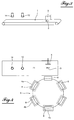
figure 2 est une vue en perspective, à plus grande échelle, de la partie indiquée en 2 sur lafigure 1 ; - les
figures 3 et 4 sont deux vues schématiques du système selon l'invention représentée enfigure 1 et2 , et - la
figure 5 est une vue d'une partie d'un instrument, pourvue d'un code d'identification. - L'invention sera décrite à titre d'exemple dans son application à un système de rangement d'instruments chirurgicaux dans des récipients de rangement prédéterminés, de façon que ces récipients contiennent chacun un ensemble d'instruments sélectionnés pour une utilisation spécifique telle qu'une intervention chirurgicale. Bien entendu, l'invention n'est pas limitée à cette application.
- Conformément à la
figure 1 , un système selon l'invention comporte un convoyeur 1 réalisé sous forme d'une bande sans fin, pour la réception des instruments chirurgicaux 3 à ranger dans un récipient de rangement 4 attitré, qui est destiné à transporter ces instruments 3 de leur endroit de mise en place sur le convoyeur jusqu'à un endroit de transfert du convoyeur, par un dispositif de transfert ou d'éjection 5, sur un dispositif 6 de transport des instruments transférés dans leur récipient de rangement attitré. - Dans l'exemple représenté, le dispositif de transport comprend un moyen de support 7 réalisé sous forme d'un carrousel, comportant à sa périphérie un certain nombre de boîtes de transport 8, chacun destiné à recevoir un instrument 3 transféré du convoyeur 1. Conformément à l'invention le carrousel se déplace selon un mouvement pas à pas, les boîtes 8 étant réparties de façon uniforme à la périphérie du carrousel. Comme on le voit notamment sur la
figure 1 , à chaque position d'arrêt du mouvement pas à pas, à l'exception de l'endroit correspondant à la position angulaire de réception des objets éjectés, est placés sur une table de support 9 un récipient de rangement 4, sur les figures en forme d'une boîte, de façon que l'instrument se trouvant dans une boîte de transport 8 puisse être transférée dans un récipient de rangement. Par conséquent, pour un nombre de N boîtes de transport 8 le système comporte N-1 de récipients de rangement. Comme le montre lafigure 2 , les boîtes de transport 8 sont montées sur le carrousel, pivotante entre une position de réception et de transport d'un instrument et une position de déchargement de celui-ci dans le récipient de rangement correspondant 4. Selon l'invention chacune de ces récipients de rangement 4 est destinée à contenir un ensemble d'instruments chirurgicaux, établi pour une utilisation prédéterminée, par exemple une intervention chirurgicale, comme cela a été énoncé plus haut. - Pour pouvoir ranger les instruments 3 de cette façon ordonnée dans les récipients de rangement 4, le système est équipé d'un dispositif de reconnaissance des instruments, au moyen d'une caméra 12 de reconnaissance des instruments 3 par lecture d'un code spécifique dont est pourvu chaque instrument. La
figure 5 montre à titre d'exemple un instrument codé par un certain nombre de points de codage répartis d'une façon unique pour cet instrument sur une zone par exemple carrée de la surface de l'instrument. Bien entendu tout autre moyen de codage pourrait être prévu. - La caméra de reconnaissance 12 des instruments, appelée ci-après caméra de décodage se trouve en amont de l'endroit de transfert.
- Dans l'exemple représenté, le système selon l'invention comporte une autre caméra notée 14 qui est une caméra de prise de vue et a pour fonction de reproduire sur son écran de visualisation 15 l'image de l'instrument qui est disposé dans son champ de vision sur le convoyeur. Cette caméra permet donc de placer l'instrument sur le convoyeur de façon que la zone 16 qui contient le code se trouve au centre de l'écran 15 et donc dans une position qui permet à la caméra de décodage 12 de lire ce code de façon optimale lorsque l'instrument se présente dans son champ de vision.
- Dans l'exemple de mise en oeuvre de l'invention les instruments chirurgicaux à ranger dans les récipients de rangement 4 sont disposés sur le convoyeur par un opérateur qui dispose d'un pupitre 17 de commande du convoyeur.
- On décrira ci-après le fonctionnement du système selon l'invention telle que représentée sur les figures et décrite ci-avant.
- Après avoir placé correctement un premier instrument 3 qui est nommé 3a pour faciliter la compréhension de l'invention, sur le convoyeur 1, avec la zone de codage sous la caméra, dans le champ de vision de celle-ci, position que l'opérateur peut surveiller grâce à l'écran, il appuie sur un bouton de son pupitre de commande 17, ce qui met en mouvement le convoyeur pour qu'il transporte l'instrument jusqu'au dispositif de transfert 5 en le faisant passer sous la caméra de décodage 12. Pour faciliter le positionnement des instruments sur le convoyeur, chaque instrument peut comporter sur ses deux faces, à savoir la face orientée vers le haut et la face à laquelle il repose sur le convoyeur, le code le caractérisant.
- Lorsque l'instrument 3a passe sous la caméra de décodage 12, celle-ci lit le code et reconnait, c'est-à-dire identifie l'instrument. Lorsque l'instrument se présente devant le dispositif de transfert celui-ci déplace l'instrument perpendiculairement à l'axe du convoyeur et le pousse sur le plan incliné 19 qui permet le glissement de l'instrument dans la boîte de transport 8 du carrousel, qui se trouve en face de lui et qui est nommé 8a.
- Entretemps, l'opérateur a placé sur le convoyeur, dans le champ de vision de la caméra de prise de vue 14 un deuxième instrument nommé 3b. Après avoir constaté que cet instrument est correctement positionné, c'est-à-dire son code se trouve au centre de l'image reproduite sur l'écran, l'opérateur appui sur le bouton de commande de son pupitre 17, ce qui fait démarrer le convoyeur qui déplace alors l'instrument à la caméra de décodage 12 pour que celle-ci puisse reconnaître, c'est-à-dire identifier l'instrument, et jusqu'au dispositif de transfert 5, d'une part, et d'autre part la rotation d'un pas du carrousel de façon que la boîte de transport 8a qui avait auparavant reçu le premier instrument 3a se trouve à la fin du pas au niveau de le premier récipient de rangement 4a. Dans cette position du carrousel, l'instrument 3a est déchargé dans ce premier récipient 4a qui devient alors le récipient de l'ensemble des instruments dont fait partie le premier instrument 3a. A la fin de ce pas de rotation une boîte de transport vide 8 nommé 8b se trouve devant le dispositif éjecteur qui pousse alors dans cette boîte le deuxième instrument 3b.
- Lorsque l'opérateur appuie à nouveau sur le bouton de commande d'un déplacement du convoyeur, après le positionnement d'un troisième instrument 3c sur celui-ci, dans le champ de vision de la caméra de vue 14, le carrousel effectue dans le temps du déplacement de l'instrument jusqu'au dispositif de transfert 5 un nouveau pas de rotation de façon qu'une boîte de transport vide 8, appelée maintenant 8c, se trouve en face de l'éjecteur. La boîte de transport 8b qui contient le deuxième instrument 3b se trouve alors au niveau du premier récipient de rangement 4a. Si le deuxième instrument fait partie de l'ensemble que ce premier récipient de rangement 4a est destiné à recevoir, l'instrument est déchargé dans ce récipient. S'il s'agit d'un instrument qui fait partie d'un autre ensemble, cet instrument est déchargé dans le deuxième récipient de rangement 4b à la fin du deuxième pas de rotation effectué lors de la reconnaissance du troisième instrument 3c que l'éjecteur a poussé dans la troisième boîte de transport 8c. Ainsi, le récipient de rangement 4b devient alors le récipient de rangement de tous les instruments de l'ensemble dont fait partie le deuxième instrument 3b.
- Ainsi, chaque étape de reconnaissance d'un instrument provoque la rotation d'un pas du carrousel. Les récipients de rangement 4 destinés à recevoir les différents ensembles d'instruments sont déterminés au fur et à mesure de la reconnaissance des instruments par la caméra de décodage. L'ensemble dont fait partie le premier instrument 3a est reçu dans le premier récipient de rangement 4a et tous les instruments qui font parti de cet ensemble seront alors déchargés dans ce récipient 4a. La reconnaissance du premier instrument qui ne fait pas partie de l'ensemble destiné au récipient de rangement 4a sera placée dans le deuxième récipient de rangement 4b. Le premier instrument reconnu qui fait partie d'un troisième ensemble est déchargé dans le troisième récipient de rangement 4c et de suite.
- La composition des récipients de rangement et leur numéro d'identification est affichée sur un écran 18 de la caméra de décodage 12 si bien que l'invention permet une parfaite traçabilité des instruments.
- Bien entendu des diverses modifications peuvent être apportées à l'invention. Ainsi, la caméra de décodage 12 pourrait être montée de façon mobile dans les directions de déplacement du convoyeur et perpendiculaire à celle-ci pour pouvoir se placer toujours de façon optimale au-dessus de la zone de codage de chaque instrument, sous la commande de la caméra de prise de vue. On pourrait aussi envisager de n'utiliser qu'une seule caméra qui sera alors avantageusement conçue pour pouvoir se positionner correctement, de façon automatique, au-dessus des instruments à reconnaître. Le temps dont doit disposer le carrousel pour effectuer un pas de rotation sera alors déterminé par le déplacement des instruments reconnus, c'est-à-dire décodés, jusqu'à l'éjecteur. Le mouvement du convoyeur est alors déclenché à la fin de l'opération de reconnaissance par la caméra ou de toute autre manière appropriée. On pourrait aussi envisager de faire fonctionner le système totalement automatiquement, sans opérateur. Dans ce cas, un pas d'avancement du convoyeur pourrait alors assurer le déplacement d'un instrument de son endroit de mise sur le convoyeur jusqu'au dispositif de transfert, et ce pas d'avancement du convoyeur, déclenchera le mouvement d'avancement d'un pas du carrousel. On pourrait aussi remplacer le carrousel par un dispositif qui déplace les boîtes de transport linéairement, de façon pas à pas, pour décharger les instruments dans des récipients de rangement alors alignées de façon appropriée. Il est encore à noter que le système comporte en plus des récipients de rangement une boîte de rebut destinée à recevoir des instruments qui n'ont pas pu être placés dans les récipients de rangement, pour des diverses raisons. On pourrait encore envisager, sans sortir du cadre de l'invention, de déterminer d'avance les récipients de rangement qui seront alors remplies selon un logiciel approprié.
Claims (9)
- Système de rangement d'objets, tels que des instruments chirurgicaux, dans des récipients de rangement prédéterminés (4), comprenant un convoyeur (1) de transport des objets (3) placés sur le convoyeur à une caméra (12) de reconnaissance des objets, par lecture d'un code d'identification que porte chaque objet, et un dispositif (6) de transport de chaque objet (3) du convoyeur dans le récipient de rangement auquel il est destiné, caractérisé en ce qu'il comprend un dispositif (5) de transfert de chaque objet reconnu (3), du convoyeur (1) dans une boîte (8) de transport de l'objet dans le récipient (4) auquel il est destiné, et un dispositif de support de cette boîte de transport (8) qui est déplaçable selon un mouvement pas à pas, chaque pas du dispositif de transport (6) correspondant à un pas d'avancement du convoyeur (1), au cours duquel un objet (3) a été reconnu par la caméra de reconnaissance (12).
- Système de rangement selon la revendication 1, caractérisé en ce que les boîtes de transport (8) sont montées sur un moyen de support mobile (7), réalisé sous forme d'un carrousel comportant à sa périphérie lesdites boîtes de transport (8) dont le nombre est au moins égal au nombre de récipients de rangement (4).
- Système de rangement selon la revendication 1, caractérisé en ce que les boîtes de transport (8) sont montées sur un moyen de support mobile se déplaçant linéairement selon un mouvement de vas et qui fait au moins autant de pas qu'il y a de récipients de rangement (4).
- Système de rangement selon les revendications 1 à 3, caractérisé en ce que le dispositif de transport (6) comporte au moins une boîte de transport (8) de plus qu'il y a de récipients de rangement (4), cette boîte supplémentaire étant destinée à décharger des instruments qui n'ont pas pus être déchargés dans un récipient de rangement, dans un récipient de rebut.
- Système de rangement selon l'une des revendications 1 à 4, caractérisé en ce chaque boîte de transport (8) est montée sur le support (7) pivotante entre une position de réception et de transport d'un objet (3) et une position de déchargement d'un objet dans un récipient de rangement (4).
- Système de rangement selon l'une des revendications 1 à 5, caractérisé en ce qu'il comprend, en amont de la caméra (12) de reconnaissance par lecture des codes des objets (3), une caméra de prise de vue (14) pour le positionnement des objets sur le convoyeur (1) dans des positions permettant la reconnaissance des objets par la caméra de reconnaissance (12).
- Système de rangement selon l'une des revendications 1 à 6, caractérisé en ce que l'ordre et le numéro des récipients de rangement (4) sont déterminés selon l'ordre d'arrivée sur le dispositif de transport (6) des objets reconnus (3).
- Système de rangement selon la revendication 7, caractérisé en ce que le récipient de rangement (4) de l'ensemble dont fait partie le premier objet reconnu est le récipient qui est éloigné d'un pas de déplacement dû dispositif de transport, de la position de réception des objets (3) à ranger.
- Système de rangement selon une des revendications 1 à 8, caractérisé en ce que les coordonnées et le contenu des récipients de rangement (4) est affiché avantageusement sur un écran de visualisation associé à la caméra de reconnaissance (12).
Applications Claiming Priority (2)
| Application Number | Priority Date | Filing Date | Title |
|---|---|---|---|
| FR1158044A FR2979903B1 (fr) | 2011-09-09 | 2011-09-09 | Systeme de rangement d'objets dans des recipients de rangement predetermines |
| PCT/FR2012/051986 WO2013034850A1 (fr) | 2011-09-09 | 2012-09-05 | Système de rangement d'objets dans des récipients de rangement prédéterminés |
Publications (2)
| Publication Number | Publication Date |
|---|---|
| EP2753435A1 EP2753435A1 (fr) | 2014-07-16 |
| EP2753435B1 true EP2753435B1 (fr) | 2016-03-09 |
Family
ID=47022953
Family Applications (1)
| Application Number | Title | Priority Date | Filing Date |
|---|---|---|---|
| EP12773019.0A Not-in-force EP2753435B1 (fr) | 2011-09-09 | 2012-09-05 | Système de rangement d'objets dans des récipients de rangement prédéterminés |
Country Status (7)
| Country | Link |
|---|---|
| US (1) | US9114435B2 (fr) |
| EP (1) | EP2753435B1 (fr) |
| JP (1) | JP6165731B2 (fr) |
| CN (1) | CN103974785B (fr) |
| CA (1) | CA2848244C (fr) |
| FR (1) | FR2979903B1 (fr) |
| WO (1) | WO2013034850A1 (fr) |
Families Citing this family (16)
| Publication number | Priority date | Publication date | Assignee | Title |
|---|---|---|---|---|
| CN104275311A (zh) * | 2014-09-27 | 2015-01-14 | 吴玲玲 | 自动归类分拣装置 |
| CN104309827A (zh) * | 2014-09-27 | 2015-01-28 | 吴玲玲 | 分拣收集装置 |
| TWI601580B (zh) * | 2015-06-15 | 2017-10-11 | Ykk Corp | Sorting device |
| US9707595B2 (en) * | 2015-12-16 | 2017-07-18 | Waste Repurposing International, Inc. | Household hazardous waste recovery |
| US10449572B2 (en) * | 2015-12-16 | 2019-10-22 | Waste Repurposing International, Inc. | Household hazardous waste recovery |
| US9639535B1 (en) | 2015-12-16 | 2017-05-02 | Waste Repurposing International, Inc. | Waste identification systems and methods |
| CN106881575B (zh) * | 2017-03-17 | 2023-07-04 | 中国东方电气集团有限公司 | 一种装配机器人的全自动分拣送料机构 |
| CN114148666B (zh) * | 2017-03-23 | 2024-01-05 | 伯克希尔格雷营业股份有限公司 | 包括自动线性处理站的用于处理物体的系统和方法 |
| CN107235317B (zh) * | 2017-06-08 | 2019-03-08 | 杭州利邮通信器材有限公司 | 货物自动输送流水线 |
| CN108030554B (zh) * | 2017-12-08 | 2020-06-05 | 青岛市海慈医疗集团 | 一种盛放医疗器械的手推车 |
| CN109171021B (zh) * | 2018-08-22 | 2021-08-27 | 青岛颐中科技有限公司 | 电子烟吸烟机的供料系统 |
| CN111110365B (zh) * | 2020-02-05 | 2020-11-06 | 青岛大学附属医院 | 一种锋利手术器械环形的传递整理装置 |
| CN111266311B (zh) * | 2020-03-18 | 2020-10-27 | 高翔 | 一种专用手术器械微粒检测装置 |
| CN111701875A (zh) * | 2020-06-30 | 2020-09-25 | 西安工业大学 | 一种类球型水果的重量分级装置 |
| CN113697458A (zh) * | 2021-09-28 | 2021-11-26 | 福建省鸿林物流有限公司 | 一种物流中转仓储系统及其方法 |
| BE1029261B1 (fr) * | 2022-08-09 | 2023-09-01 | Univ Zhengzhou Aeronautics | Un équipement logistique intelligent pour le tri automatique |
Family Cites Families (17)
| Publication number | Priority date | Publication date | Assignee | Title |
|---|---|---|---|---|
| JPS5793482A (en) * | 1980-11-29 | 1982-06-10 | Tsubakimoto Chain Co | Automatic read device which is capable of reading plural times by same reader |
| JPH06134407A (ja) * | 1992-10-30 | 1994-05-17 | Tec Ichi:Kk | 自動選別装置 |
| FR2725640B1 (fr) * | 1994-10-12 | 1997-01-10 | Pellenc Sa | Machine et procede pour le tri d'objets divers a l'aide d'au moins un bras robotise |
| JP2837123B2 (ja) * | 1995-12-28 | 1998-12-14 | 株式会社ケーヒン | 部品管理装置 |
| JP3117398B2 (ja) * | 1996-01-16 | 2000-12-11 | 日本ファイリング株式会社 | 図書の自動仕分け装置 |
| JPH1095525A (ja) * | 1996-09-24 | 1998-04-14 | Nippon Filing Co Ltd | 図書の自動仕分け装置 |
| NO309975B1 (no) * | 1999-07-06 | 2001-04-30 | Mach Design Group As | FremgangsmÕte og anordning til sortering og pakking av usorterte gjenstander |
| US7138596B2 (en) * | 2001-08-01 | 2006-11-21 | Pippin James M | Apparatus and method for mail sorting |
| US6762382B1 (en) * | 2001-10-02 | 2004-07-13 | Innovative Picking Technologies, Inc. | Track-type sortation system |
| US6671580B2 (en) * | 2001-12-28 | 2003-12-30 | Storage Technology Corporation | Outer route for robots in a horizontal storage library |
| NZ518851A (en) * | 2002-05-08 | 2004-12-24 | Anzpac Systems Ltd | Sorting apparatus and method |
| CN2555109Y (zh) * | 2002-08-03 | 2003-06-11 | 浙江大学 | 利用移位寄存器控制的水果实时分级控制系统 |
| JP2005247458A (ja) * | 2004-03-02 | 2005-09-15 | Yamagata Yakult Hanbai Kk | 物品判定方法および装置 |
| US8030588B2 (en) * | 2006-10-26 | 2011-10-04 | Align Technology, Inc. | System and method for sorting items |
| BRPI0806564B1 (pt) * | 2007-01-12 | 2018-10-16 | Opex Corp | aparelho para classificar uma pluralidade de itens. |
| DE102009021073A1 (de) * | 2009-05-13 | 2010-11-18 | Bsautomatisierung Gmbh | Sortiervorrichtung |
| FI122025B (fi) * | 2009-09-14 | 2011-07-29 | Maricap Oy | Menetelmä jätteiden lajittelemiseksi ja jätteidenlajittelujärjestelmä |
-
2011
- 2011-09-09 FR FR1158044A patent/FR2979903B1/fr not_active Expired - Fee Related
-
2012
- 2012-09-05 CA CA2848244A patent/CA2848244C/fr not_active Expired - Fee Related
- 2012-09-05 JP JP2014529049A patent/JP6165731B2/ja not_active Expired - Fee Related
- 2012-09-05 CN CN201280054673.4A patent/CN103974785B/zh not_active Expired - Fee Related
- 2012-09-05 WO PCT/FR2012/051986 patent/WO2013034850A1/fr active Application Filing
- 2012-09-05 EP EP12773019.0A patent/EP2753435B1/fr not_active Not-in-force
-
2014
- 2014-03-07 US US14/200,740 patent/US9114435B2/en not_active Expired - Fee Related
Also Published As
| Publication number | Publication date |
|---|---|
| FR2979903A1 (fr) | 2013-03-15 |
| JP2014530153A (ja) | 2014-11-17 |
| JP6165731B2 (ja) | 2017-07-19 |
| CN103974785B (zh) | 2016-05-25 |
| CA2848244A1 (fr) | 2013-03-14 |
| EP2753435A1 (fr) | 2014-07-16 |
| CA2848244C (fr) | 2019-01-08 |
| CN103974785A (zh) | 2014-08-06 |
| US20140374215A1 (en) | 2014-12-25 |
| US9114435B2 (en) | 2015-08-25 |
| WO2013034850A1 (fr) | 2013-03-14 |
| FR2979903B1 (fr) | 2013-11-22 |
Similar Documents
| Publication | Publication Date | Title |
|---|---|---|
| EP2753435B1 (fr) | Système de rangement d'objets dans des récipients de rangement prédéterminés | |
| EP3016293B1 (fr) | Dispositif de fixation d'une carte sim et terminal mobile | |
| FR2709625A1 (fr) | Dispositif et procédé de coopération entre mémoires dans un terminal de télécommunications mobile. | |
| EP1386482B1 (fr) | Procede de selection d'une image de logiciel executable | |
| WO2006113078A3 (fr) | Procede et systeme permettant d'acceder et de visionner des fichiers sur des dispositifs mobiles | |
| WO2006039493A3 (fr) | Enregistrements virtuels ordonnes | |
| FR3009518A1 (fr) | ||
| US9998164B2 (en) | Device for affixing SIM card and mobile terminal | |
| FR2799331A1 (fr) | Dispositif d'enregistrement tenant dans la main et procede pour son utilisation | |
| EP0628837B1 (fr) | Procédé et dispositif pour déterminer la localisation d'une cible | |
| EP2548821A1 (fr) | Système de stockage et de délivrance de boites parallelépipèdiques telles que des boites de médicament | |
| EP1720108A3 (fr) | Stockage d'image | |
| FR3027330A1 (fr) | Terminal de paiement mobile comprenant une fonction de deverrouillage embarquee | |
| EP2794131B1 (fr) | Dispositif et procédé d'empilage et de chargement d'objets plats sur chant dans un bac multi-compartiments, machine de tri postal et procédé de tri postal | |
| CA2551336A1 (fr) | Instrument tel qu'un instrument chirurgical | |
| EP3206805A1 (fr) | Procédé, dispositif et ligne d'inspection pour la lecture optique de reliefs sur une paroi latérale d'un récipient | |
| FR2551472A1 (fr) | Dispositif de traitement automatique d'un ensemble de pieces sur chacune desquelles doivent etre piques un ou plusieurs motifs de points predetermines | |
| US20240099357A1 (en) | Automatic cigarette injection machine | |
| FR3025330A1 (fr) | Coque pour systeme de telecommunication portable | |
| EP3403218A1 (fr) | Dispositif de selection et description de points d'interets dans une sequence d'images, par exemple pour l'appariement de points d'interets | |
| FR2881868A1 (fr) | Dispositif de rangement de disques de stockage d'informations | |
| FR2918197A1 (fr) | Machine pour personnaliser des cartes a puces avec une cadence elevee. | |
| Schuchart Jr | The Search Goes On[Content-addressed storage technology] | |
| WO2018100289A1 (fr) | Navigation dans des données utilisateur | |
| BE1025794A1 (fr) | Système et méthode de tri, de comptage et de rangement automatisés de couverts |
Legal Events
| Date | Code | Title | Description |
|---|---|---|---|
| PUAI | Public reference made under article 153(3) epc to a published international application that has entered the european phase |
Free format text: ORIGINAL CODE: 0009012 |
|
| 17P | Request for examination filed |
Effective date: 20140408 |
|
| AK | Designated contracting states |
Kind code of ref document: A1 Designated state(s): AL AT BE BG CH CY CZ DE DK EE ES FI FR GB GR HR HU IE IS IT LI LT LU LV MC MK MT NL NO PL PT RO RS SE SI SK SM TR |
|
| DAX | Request for extension of the european patent (deleted) | ||
| GRAP | Despatch of communication of intention to grant a patent |
Free format text: ORIGINAL CODE: EPIDOSNIGR1 |
|
| INTG | Intention to grant announced |
Effective date: 20150707 |
|
| GRAS | Grant fee paid |
Free format text: ORIGINAL CODE: EPIDOSNIGR3 |
|
| GRAA | (expected) grant |
Free format text: ORIGINAL CODE: 0009210 |
|
| AK | Designated contracting states |
Kind code of ref document: B1 Designated state(s): AL AT BE BG CH CY CZ DE DK EE ES FI FR GB GR HR HU IE IS IT LI LT LU LV MC MK MT NL NO PL PT RO RS SE SI SK SM TR |
|
| REG | Reference to a national code |
Ref country code: GB Ref legal event code: FG4D Free format text: NOT ENGLISH |
|
| REG | Reference to a national code |
Ref country code: AT Ref legal event code: REF Ref document number: 779096 Country of ref document: AT Kind code of ref document: T Effective date: 20160315 Ref country code: CH Ref legal event code: EP |
|
| REG | Reference to a national code |
Ref country code: IE Ref legal event code: FG4D Free format text: LANGUAGE OF EP DOCUMENT: FRENCH |
|
| REG | Reference to a national code |
Ref country code: DE Ref legal event code: R096 Ref document number: 602012015422 Country of ref document: DE |
|
| REG | Reference to a national code |
Ref country code: LT Ref legal event code: MG4D |
|
| REG | Reference to a national code |
Ref country code: NL Ref legal event code: MP Effective date: 20160309 |
|
| PG25 | Lapsed in a contracting state [announced via postgrant information from national office to epo] |
Ref country code: FI Free format text: LAPSE BECAUSE OF FAILURE TO SUBMIT A TRANSLATION OF THE DESCRIPTION OR TO PAY THE FEE WITHIN THE PRESCRIBED TIME-LIMIT Effective date: 20160309 Ref country code: HR Free format text: LAPSE BECAUSE OF FAILURE TO SUBMIT A TRANSLATION OF THE DESCRIPTION OR TO PAY THE FEE WITHIN THE PRESCRIBED TIME-LIMIT Effective date: 20160309 Ref country code: NO Free format text: LAPSE BECAUSE OF FAILURE TO SUBMIT A TRANSLATION OF THE DESCRIPTION OR TO PAY THE FEE WITHIN THE PRESCRIBED TIME-LIMIT Effective date: 20160609 Ref country code: ES Free format text: LAPSE BECAUSE OF FAILURE TO SUBMIT A TRANSLATION OF THE DESCRIPTION OR TO PAY THE FEE WITHIN THE PRESCRIBED TIME-LIMIT Effective date: 20160309 Ref country code: GR Free format text: LAPSE BECAUSE OF FAILURE TO SUBMIT A TRANSLATION OF THE DESCRIPTION OR TO PAY THE FEE WITHIN THE PRESCRIBED TIME-LIMIT Effective date: 20160610 |
|
| REG | Reference to a national code |
Ref country code: AT Ref legal event code: MK05 Ref document number: 779096 Country of ref document: AT Kind code of ref document: T Effective date: 20160309 |
|
| PG25 | Lapsed in a contracting state [announced via postgrant information from national office to epo] |
Ref country code: PL Free format text: LAPSE BECAUSE OF FAILURE TO SUBMIT A TRANSLATION OF THE DESCRIPTION OR TO PAY THE FEE WITHIN THE PRESCRIBED TIME-LIMIT Effective date: 20160309 Ref country code: LV Free format text: LAPSE BECAUSE OF FAILURE TO SUBMIT A TRANSLATION OF THE DESCRIPTION OR TO PAY THE FEE WITHIN THE PRESCRIBED TIME-LIMIT Effective date: 20160309 Ref country code: SE Free format text: LAPSE BECAUSE OF FAILURE TO SUBMIT A TRANSLATION OF THE DESCRIPTION OR TO PAY THE FEE WITHIN THE PRESCRIBED TIME-LIMIT Effective date: 20160309 Ref country code: RS Free format text: LAPSE BECAUSE OF FAILURE TO SUBMIT A TRANSLATION OF THE DESCRIPTION OR TO PAY THE FEE WITHIN THE PRESCRIBED TIME-LIMIT Effective date: 20160309 Ref country code: LT Free format text: LAPSE BECAUSE OF FAILURE TO SUBMIT A TRANSLATION OF THE DESCRIPTION OR TO PAY THE FEE WITHIN THE PRESCRIBED TIME-LIMIT Effective date: 20160309 Ref country code: NL Free format text: LAPSE BECAUSE OF FAILURE TO SUBMIT A TRANSLATION OF THE DESCRIPTION OR TO PAY THE FEE WITHIN THE PRESCRIBED TIME-LIMIT Effective date: 20160309 |
|
| PG25 | Lapsed in a contracting state [announced via postgrant information from national office to epo] |
Ref country code: EE Free format text: LAPSE BECAUSE OF FAILURE TO SUBMIT A TRANSLATION OF THE DESCRIPTION OR TO PAY THE FEE WITHIN THE PRESCRIBED TIME-LIMIT Effective date: 20160309 Ref country code: IS Free format text: LAPSE BECAUSE OF FAILURE TO SUBMIT A TRANSLATION OF THE DESCRIPTION OR TO PAY THE FEE WITHIN THE PRESCRIBED TIME-LIMIT Effective date: 20160709 |
|
| PG25 | Lapsed in a contracting state [announced via postgrant information from national office to epo] |
Ref country code: SK Free format text: LAPSE BECAUSE OF FAILURE TO SUBMIT A TRANSLATION OF THE DESCRIPTION OR TO PAY THE FEE WITHIN THE PRESCRIBED TIME-LIMIT Effective date: 20160309 Ref country code: PT Free format text: LAPSE BECAUSE OF FAILURE TO SUBMIT A TRANSLATION OF THE DESCRIPTION OR TO PAY THE FEE WITHIN THE PRESCRIBED TIME-LIMIT Effective date: 20160711 Ref country code: SM Free format text: LAPSE BECAUSE OF FAILURE TO SUBMIT A TRANSLATION OF THE DESCRIPTION OR TO PAY THE FEE WITHIN THE PRESCRIBED TIME-LIMIT Effective date: 20160309 Ref country code: AT Free format text: LAPSE BECAUSE OF FAILURE TO SUBMIT A TRANSLATION OF THE DESCRIPTION OR TO PAY THE FEE WITHIN THE PRESCRIBED TIME-LIMIT Effective date: 20160309 Ref country code: CZ Free format text: LAPSE BECAUSE OF FAILURE TO SUBMIT A TRANSLATION OF THE DESCRIPTION OR TO PAY THE FEE WITHIN THE PRESCRIBED TIME-LIMIT Effective date: 20160309 Ref country code: RO Free format text: LAPSE BECAUSE OF FAILURE TO SUBMIT A TRANSLATION OF THE DESCRIPTION OR TO PAY THE FEE WITHIN THE PRESCRIBED TIME-LIMIT Effective date: 20160309 |
|
| REG | Reference to a national code |
Ref country code: DE Ref legal event code: R097 Ref document number: 602012015422 Country of ref document: DE |
|
| PG25 | Lapsed in a contracting state [announced via postgrant information from national office to epo] |
Ref country code: IT Free format text: LAPSE BECAUSE OF FAILURE TO SUBMIT A TRANSLATION OF THE DESCRIPTION OR TO PAY THE FEE WITHIN THE PRESCRIBED TIME-LIMIT Effective date: 20160309 |
|
| PLBE | No opposition filed within time limit |
Free format text: ORIGINAL CODE: 0009261 |
|
| STAA | Information on the status of an ep patent application or granted ep patent |
Free format text: STATUS: NO OPPOSITION FILED WITHIN TIME LIMIT |
|
| REG | Reference to a national code |
Ref country code: FR Ref legal event code: PLFP Year of fee payment: 5 |
|
| PG25 | Lapsed in a contracting state [announced via postgrant information from national office to epo] |
Ref country code: DK Free format text: LAPSE BECAUSE OF FAILURE TO SUBMIT A TRANSLATION OF THE DESCRIPTION OR TO PAY THE FEE WITHIN THE PRESCRIBED TIME-LIMIT Effective date: 20160309 |
|
| 26N | No opposition filed |
Effective date: 20161212 |
|
| PG25 | Lapsed in a contracting state [announced via postgrant information from national office to epo] |
Ref country code: BE Free format text: LAPSE BECAUSE OF NON-PAYMENT OF DUE FEES Effective date: 20160930 Ref country code: BG Free format text: LAPSE BECAUSE OF FAILURE TO SUBMIT A TRANSLATION OF THE DESCRIPTION OR TO PAY THE FEE WITHIN THE PRESCRIBED TIME-LIMIT Effective date: 20160609 |
|
| PG25 | Lapsed in a contracting state [announced via postgrant information from national office to epo] |
Ref country code: MC Free format text: LAPSE BECAUSE OF FAILURE TO SUBMIT A TRANSLATION OF THE DESCRIPTION OR TO PAY THE FEE WITHIN THE PRESCRIBED TIME-LIMIT Effective date: 20160309 |
|
| REG | Reference to a national code |
Ref country code: CH Ref legal event code: PL |
|
| PG25 | Lapsed in a contracting state [announced via postgrant information from national office to epo] |
Ref country code: SI Free format text: LAPSE BECAUSE OF FAILURE TO SUBMIT A TRANSLATION OF THE DESCRIPTION OR TO PAY THE FEE WITHIN THE PRESCRIBED TIME-LIMIT Effective date: 20160309 |
|
| REG | Reference to a national code |
Ref country code: IE Ref legal event code: MM4A |
|
| PG25 | Lapsed in a contracting state [announced via postgrant information from national office to epo] |
Ref country code: IE Free format text: LAPSE BECAUSE OF NON-PAYMENT OF DUE FEES Effective date: 20160905 Ref country code: LI Free format text: LAPSE BECAUSE OF NON-PAYMENT OF DUE FEES Effective date: 20160930 Ref country code: CH Free format text: LAPSE BECAUSE OF NON-PAYMENT OF DUE FEES Effective date: 20160930 |
|
| PG25 | Lapsed in a contracting state [announced via postgrant information from national office to epo] |
Ref country code: LU Free format text: LAPSE BECAUSE OF NON-PAYMENT OF DUE FEES Effective date: 20160905 |
|
| REG | Reference to a national code |
Ref country code: BE Ref legal event code: MM Effective date: 20160930 |
|
| REG | Reference to a national code |
Ref country code: FR Ref legal event code: PLFP Year of fee payment: 6 |
|
| PG25 | Lapsed in a contracting state [announced via postgrant information from national office to epo] |
Ref country code: HU Free format text: LAPSE BECAUSE OF FAILURE TO SUBMIT A TRANSLATION OF THE DESCRIPTION OR TO PAY THE FEE WITHIN THE PRESCRIBED TIME-LIMIT; INVALID AB INITIO Effective date: 20120905 |
|
| PG25 | Lapsed in a contracting state [announced via postgrant information from national office to epo] |
Ref country code: MK Free format text: LAPSE BECAUSE OF FAILURE TO SUBMIT A TRANSLATION OF THE DESCRIPTION OR TO PAY THE FEE WITHIN THE PRESCRIBED TIME-LIMIT Effective date: 20160309 Ref country code: CY Free format text: LAPSE BECAUSE OF FAILURE TO SUBMIT A TRANSLATION OF THE DESCRIPTION OR TO PAY THE FEE WITHIN THE PRESCRIBED TIME-LIMIT Effective date: 20160309 Ref country code: MT Free format text: LAPSE BECAUSE OF FAILURE TO SUBMIT A TRANSLATION OF THE DESCRIPTION OR TO PAY THE FEE WITHIN THE PRESCRIBED TIME-LIMIT Effective date: 20160309 |
|
| REG | Reference to a national code |
Ref country code: FR Ref legal event code: PLFP Year of fee payment: 7 |
|
| PG25 | Lapsed in a contracting state [announced via postgrant information from national office to epo] |
Ref country code: TR Free format text: LAPSE BECAUSE OF FAILURE TO SUBMIT A TRANSLATION OF THE DESCRIPTION OR TO PAY THE FEE WITHIN THE PRESCRIBED TIME-LIMIT Effective date: 20160309 Ref country code: AL Free format text: LAPSE BECAUSE OF FAILURE TO SUBMIT A TRANSLATION OF THE DESCRIPTION OR TO PAY THE FEE WITHIN THE PRESCRIBED TIME-LIMIT Effective date: 20160309 |
|
| PGFP | Annual fee paid to national office [announced via postgrant information from national office to epo] |
Ref country code: DE Payment date: 20180814 Year of fee payment: 7 Ref country code: FR Payment date: 20180813 Year of fee payment: 7 |
|
| PGFP | Annual fee paid to national office [announced via postgrant information from national office to epo] |
Ref country code: GB Payment date: 20180813 Year of fee payment: 7 |
|
| REG | Reference to a national code |
Ref country code: DE Ref legal event code: R119 Ref document number: 602012015422 Country of ref document: DE |
|
| PG25 | Lapsed in a contracting state [announced via postgrant information from national office to epo] |
Ref country code: DE Free format text: LAPSE BECAUSE OF NON-PAYMENT OF DUE FEES Effective date: 20200401 |
|
| GBPC | Gb: european patent ceased through non-payment of renewal fee |
Effective date: 20190905 |
|
| PG25 | Lapsed in a contracting state [announced via postgrant information from national office to epo] |
Ref country code: GB Free format text: LAPSE BECAUSE OF NON-PAYMENT OF DUE FEES Effective date: 20190905 Ref country code: FR Free format text: LAPSE BECAUSE OF NON-PAYMENT OF DUE FEES Effective date: 20190930 |