EP2739463B1 - System und verfahren zum auf-und/oder abwickeln von zufuhrrollen - Google Patents
System und verfahren zum auf-und/oder abwickeln von zufuhrrollen Download PDFInfo
- Publication number
- EP2739463B1 EP2739463B1 EP13739832.7A EP13739832A EP2739463B1 EP 2739463 B1 EP2739463 B1 EP 2739463B1 EP 13739832 A EP13739832 A EP 13739832A EP 2739463 B1 EP2739463 B1 EP 2739463B1
- Authority
- EP
- European Patent Office
- Prior art keywords
- station
- reel
- winding
- section
- liner
- Prior art date
- Legal status (The legal status is an assumption and is not a legal conclusion. Google has not performed a legal analysis and makes no representation as to the accuracy of the status listed.)
- Not-in-force
Links
- 238000004804 winding Methods 0.000 title claims description 112
- 238000000034 method Methods 0.000 title claims description 20
- 239000000463 material Substances 0.000 claims description 33
- 230000007246 mechanism Effects 0.000 claims description 15
- 238000001514 detection method Methods 0.000 claims description 10
- 230000003287 optical effect Effects 0.000 claims description 7
- 230000001419 dependent effect Effects 0.000 description 5
- 231100001261 hazardous Toxicity 0.000 description 5
- 230000008878 coupling Effects 0.000 description 3
- 238000010168 coupling process Methods 0.000 description 3
- 238000005859 coupling reaction Methods 0.000 description 3
- 230000009471 action Effects 0.000 description 2
- 230000008859 change Effects 0.000 description 2
- 230000008569 process Effects 0.000 description 2
- 230000003247 decreasing effect Effects 0.000 description 1
- 239000000835 fiber Substances 0.000 description 1
- 239000002184 metal Substances 0.000 description 1
- 230000002265 prevention Effects 0.000 description 1
- 230000002787 reinforcement Effects 0.000 description 1
Images

Classifications
-
- B—PERFORMING OPERATIONS; TRANSPORTING
- B29—WORKING OF PLASTICS; WORKING OF SUBSTANCES IN A PLASTIC STATE IN GENERAL
- B29D—PRODUCING PARTICULAR ARTICLES FROM PLASTICS OR FROM SUBSTANCES IN A PLASTIC STATE
- B29D30/00—Producing pneumatic or solid tyres or parts thereof
-
- B—PERFORMING OPERATIONS; TRANSPORTING
- B29—WORKING OF PLASTICS; WORKING OF SUBSTANCES IN A PLASTIC STATE IN GENERAL
- B29D—PRODUCING PARTICULAR ARTICLES FROM PLASTICS OR FROM SUBSTANCES IN A PLASTIC STATE
- B29D30/00—Producing pneumatic or solid tyres or parts thereof
- B29D30/0016—Handling tyres or parts thereof, e.g. supplying, storing, conveying
-
- B—PERFORMING OPERATIONS; TRANSPORTING
- B29—WORKING OF PLASTICS; WORKING OF SUBSTANCES IN A PLASTIC STATE IN GENERAL
- B29D—PRODUCING PARTICULAR ARTICLES FROM PLASTICS OR FROM SUBSTANCES IN A PLASTIC STATE
- B29D30/00—Producing pneumatic or solid tyres or parts thereof
- B29D30/06—Pneumatic tyres or parts thereof (e.g. produced by casting, moulding, compression moulding, injection moulding, centrifugal casting)
- B29D30/08—Building tyres
-
- B—PERFORMING OPERATIONS; TRANSPORTING
- B65—CONVEYING; PACKING; STORING; HANDLING THIN OR FILAMENTARY MATERIAL
- B65H—HANDLING THIN OR FILAMENTARY MATERIAL, e.g. SHEETS, WEBS, CABLES
- B65H19/00—Changing the web roll
- B65H19/22—Changing the web roll in winding mechanisms or in connection with winding operations
- B65H19/30—Lifting, transporting, or removing the web roll; Inserting core
-
- B—PERFORMING OPERATIONS; TRANSPORTING
- B65—CONVEYING; PACKING; STORING; HANDLING THIN OR FILAMENTARY MATERIAL
- B65H—HANDLING THIN OR FILAMENTARY MATERIAL, e.g. SHEETS, WEBS, CABLES
- B65H67/00—Replacing or removing cores, receptacles, or completed packages at paying-out, winding, or depositing stations
- B65H67/04—Arrangements for removing completed take-up packages and or replacing by cores, formers, or empty receptacles at winding or depositing stations; Transferring material between adjacent full and empty take-up elements
- B65H67/0405—Arrangements for removing completed take-up packages or for loading an empty core
-
- B—PERFORMING OPERATIONS; TRANSPORTING
- B29—WORKING OF PLASTICS; WORKING OF SUBSTANCES IN A PLASTIC STATE IN GENERAL
- B29D—PRODUCING PARTICULAR ARTICLES FROM PLASTICS OR FROM SUBSTANCES IN A PLASTIC STATE
- B29D30/00—Producing pneumatic or solid tyres or parts thereof
- B29D30/0016—Handling tyres or parts thereof, e.g. supplying, storing, conveying
- B29D2030/0038—Handling tyre parts or semi-finished parts, excluding beads, e.g., storing, transporting, transferring
-
- B—PERFORMING OPERATIONS; TRANSPORTING
- B65—CONVEYING; PACKING; STORING; HANDLING THIN OR FILAMENTARY MATERIAL
- B65H—HANDLING THIN OR FILAMENTARY MATERIAL, e.g. SHEETS, WEBS, CABLES
- B65H2301/00—Handling processes for sheets or webs
- B65H2301/30—Orientation, displacement, position of the handled material
- B65H2301/36—Positioning; Changing position
- B65H2301/364—Positioning; Changing position of material in roll
-
- B—PERFORMING OPERATIONS; TRANSPORTING
- B65—CONVEYING; PACKING; STORING; HANDLING THIN OR FILAMENTARY MATERIAL
- B65H—HANDLING THIN OR FILAMENTARY MATERIAL, e.g. SHEETS, WEBS, CABLES
- B65H2801/00—Application field
- B65H2801/93—Tyres
Definitions
- the invention relates to a system for the winding-up and/or unwinding of rubber sheet material for tyres and an intervening liner onto or from storage reels.
- a system for the winding-up or unwinding of rubber sheet material for tyres and an intervening liner onto and from storage reels.
- a storage reel and a liner reel are manually lifted and loaded onto a winding station.
- operators have to replace the storage reel and the liner reel at the winding station with a new storage reel and a new liner reel, respectively.
- These changing operations interrupt the winding process and are furthermore hazardous due to the weight and size of the reels and the proximity of various moving parts of the winding station.
- US 1,648,990 A discloses a wind-up device for sheet-rubber stock, comprises a pair of winding units each slidably laterally out of operative relation to the belt.
- US 1,891,273 A discloses a frame, a support rotatable upon said frame and having opposite heads provided with a plurality of material-receiving reels.
- EP 1 236 669 A discloses a tandem mobile cartridge for loading, storing and delivering continuous elastomeric strips of tire material from a forming station to a tire building station.
- WO 2011/101738 A discloses an apparatus with a first storage coil, a first collecting member, a second storage coil and a second collecting member arranged side-by-side on a movable carriage, to be wound/unwound alternately.
- US 2005/0189448 A discloses a reel spool storage and loading device to be used by reel-up machines that wind webs, e.g. tissue, onto successive spools to form web rolls.
- the reel-up machine comprises an upper portion with two or more elevation of rails to store empty spools. The stored spools are ready to be lowered and loaded into the reeling station below.
- WO 2010/097515 A discloses a movable storage movable between at least two target stations for receiving, moving and handling over machine reels intended for the handling of a fiber web.
- the invention provides a system for the winding-up and/or unwinding of rubber sheet material for tyres and an intervening liner onto or from storage reels, as defined in claim 1, the system comprising a first reel handling section, a second reel handling section and a winding section located between the first reel handling section and the second reel handling section, wherein the system is provided with a first station and a second station, wherein each station comprises a first set of carrying elements for holding a storage reel and a second set of carrying elements for holding a liner reel substantially in tandem with respect to the storage reel, wherein the first station and the second station are stationed in a handling position in the first reel handling section and the second reel handling section, respectively, for handling the loading and/or unloading of the storage reels and the liner reels onto or from the stations, and wherein the first station and the second station are arranged to be alternately moved from their respective handling positions in the reel handling sections into a winding position in the winding section and vice versa.
- the reels from the station that is in the reel handling section can already be unloaded and new reels can be loaded while the rubber sheet material is being wound-up or unwound onto or from the storage reel at the other station which, at the same time, is in the winding position in the winding section.
- a new set of a storage reel and a liner reel can already be loaded onto the station that is in the reel handling section, prior to the entry of that station into the winding section.
- the time to change the reels for winding-up and/or unwinding can be reduced and, as a result, the interruption in the flow of the rubber sheet material can be reduced.
- the amount of operations which are to be performed in the hazardous environment of the winding section can be reduced or even eliminated.
- first station and the second station are operationally coupled so as to be moved dependently of each other, wherein the second station is in the handling position in its respective reel handling section when the first station is in the winding position in the winding section, and vice versa.
- first station and the second station are operationally coupled to each other so as to be jointly moveable. By jointly moving the first station and the second station, it can be automatically achieved that the movement of the first station into the winding position causes the second station to be moved into its respective handling position, and vice versa.
- first station and the second station are fixedly attached to each other.
- the fixed attachment between first station and the second station can ensure that they can be moved in unison.
- the system comprises a first divider which is placed between the first station and the second station.
- the first divider can prevent or detect a passage of an operator or an object from the first station to the second station and vice versa. Therefore, the first divider can shield one station from the other.
- the first divider is operationally coupled to the stations so as to be moved dependently of the stations, wherein the first divider shields the first station at the side of the first station facing towards the second reel handling section when the first station is in the winding position in the winding section, and wherein the first divider shields the second station at the side of the second station facing towards the first reel handling section when the second station is in the winding position.
- the first divider is operationally coupled to the stations so as to be jointly moveable.
- the first divider By jointly moving the first station, the second station and the first divider, it can be automatically achieved that the movement of the first station into the winding position causes the first divider to shield the side of the first station facing towards the second reel handling section, and that the movement of the second station into the winding position causes the first divider to shield the side of the second station facing towards the first reel handling section.
- the first divider is fixedly attached to at least one of the stations.
- the fixed attachment between the first divider and the first station and/or the second station can ensure that they can be moved in unison.
- the system comprises second and/or further dividers which, in combination with the first divider, are arranged to form a shield around the winding section and the first reel handling section when the first station is in the winding position in the winding section, and which, in combination with the first divider, are arranged to form a shield around the winding section and the second reel handling section when the second station is in the winding position in the winding section.
- the second and/or further dividers are alternately moveable between a first position wherein they shield the first reel handling section and a second position wherein they shield the second reel handling section.
- the one or more dividers are each defined by a boundary of the group comprising a fence, a wall, an optical detection field or an array of light beams.
- a fence or a wall can prevent physical passage of objects or an operator.
- the optical detection field or the array of light beams can not physically prevent such passage, they can detect such passage and take appropriate action, such as shutting down the system.
- a divider being defined by an optical detection field or an array of light beams, said divider can simply and instantly be activated or de-activated.
- each station comprises a carriage which allows for the station to be moved between its respective reel handling section and the winding section, wherein, preferably, the first set of carrying elements and the second set of carrying elements extend on opposite sides of the carriage. With the carrying elements extending on both sides of the carriage, the weight of the reels can be evenly balanced with respect to the carriage.
- the system comprises a guide that extends through each of the sections in the direction in which the sections are located adjacent to each other, wherein the carriages of the stations are placed on the guide.
- the guide can facilitate the movement of the carriages between the various sections.
- first set of carrying elements and the second set of carrying elements are moveable with respect to each other in the axial direction of the reels.
- the sets of carrying elements can be moved in the axial direction of the reels to align the set of carrying elements for loading or unloading of the reel.
- the sets of carrying elements can be moved in the axial direction of the reels to adjust the tandem alignment of the reels during winding-up or unwinding, to correct for irregularities in the material to be wound.
- each set of carrying elements comprise two arms which are arranged for engaging an axis of a reel from both sides of the reel, wherein, for each set of carrying elements, the arms are moveable with respect to each other in the axial direction of the reel.
- the arms are moveable with respect to each other in a translatory manner in the axial direction of the reel.
- the translatory movement can ensure that the arms are able to coaxially engage a reel.
- system further comprises a first lift mechanism at the first reel handling section and a second lift mechanism at the second reel handling section, wherein the lift mechanisms are arranged for lifting or lowering the storage reels and the liners reels to and from their respective stations.
- the lift mechanisms can reduce the hazard for operators handling during the handling of heavy reels.
- the invention provides a method as defined in claim 12, for the winding-up and/or unwinding of rubber sheet material for tyres and an intervening liner onto or from storage reels, using a system comprising a first reel handling section, a second reel handling section and a winding section located between the first reel handling section and the second reel handling section, wherein the system is provided with a first station and a second station, wherein each station comprises a first set of carrying elements for holding a storage reel and a second set of carrying elements for holding a liner reel substantially in tandem with respect to the storage reel, wherein the method comprises the steps of stationing the first station and the second station in a handling position in the first reel handling section and the second reel handling section, respectively, loading and/or unloading the storage reels and the liner reels onto or from the stations, and alternately moving the first station and the second station from their respective handling positions in the reel handling sections into a winding position in the winding section and vice versa.
- first station and the second station are moved dependently of each other, wherein the method comprises the step of moving the second station into the handling position in its respective reel handling section when the first station is in the winding position in the winding section, and vice versa.
- first station and the second station are jointly moved. By jointly moving the first station and the second station, it can be automatically achieved that the movement of the first station into the winding position causes the second station to be moved into its respective handling position, and vice versa.
- the system comprises a first divider which is placed between the first station and the second station, wherein the method comprises the steps of moving the first divider dependently of the stations, thereby shielding the first station at the side of the first station facing towards the second reel handling section when the first station is in the winding position in the winding section, and shielding the second station at the side of the second station facing towards the first reel handling section when the second station is in the winding position.
- the first divider and the stations are jointly moved.
- the system comprises a sensor, wherein the method comprises the steps of detecting the end of the liner with the sensor as the liner is being wound-up onto one of the reels, controlling the rotation of the reel onto which the liner is being wound-up based on the detected end of the liner so that, after the controlled rotation, the detected end of the liner is located in a predetermined position on the reel.
- the predetermined position of the end of the liner on the reel can easily be found by an operator.
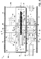
- Figures 1 and 2 show a system 1 for the winding-up and/or unwinding of rubberized sheets or rubber sheet material 91 for tyres and an intervening liner 92 onto or from storage reels 6 according to an exemplary embodiment of the invention.
- the rubber sheet material 91 comprises a plurality of cut rubber strips with metal reinforcement cord. Such strips are generally known as breakers which form the carcass layer of a green tyre.
- the liner 92 comprises a continuous layer of non-sticky material.
- the liner 92 is supplied from a roll 70 of liner 92 on the full liner reel 7 and combined with the rubber sheet material 91 before being wound-up onto an initially empty storage reel 6 to form a roll 60.
- the rubber sheet material 91 is imposed on the intervening liner 92 so that, when the rubber sheet material 91 is wound-up as a roll 60 onto the storage reel 6, the rubber sheet material 91 of each winding of the roll 60 around the storage reel 6 is separated by the intervening liner 92 from the previous and/or the next winding of rubber sheet material 91.
- the intervening liner 92 sticking together of multiple windings of the rubber sheet material 91 within the roll 60 can be prevented.
- the liner 92 and the rubber sheet material 91 are taken back onto an initially empty liner reel 7 from a full storage reel 6 and the rubber sheet material 91 is separated from the liner 92.
- the system 1 comprises a first station 2 and a second station 3 which are arranged to be alternately moveable in an alternation direction G between a reel handling position for handling the loading and unloading of storage reels 6 and liner reels 7 and a winding position for the winding-up or unwinding of storage reels 6 and liner reels 7 in a manner which will be described in more detail hereafter.
- the system 1 can be divided into a first reel handling section 11, a winding section 12 and a second reel handling section 13.
- the winding section 12 is located in-between the first reel handling section 11 and the second reel handling section 13.
- the sections 11-13 are located adjacent to each other in the alternation direction G.
- the sections 11-13 are of elongated, rectangular shape and border with each other along their longitudinal sides.
- the system 1 is provided with a main guide 8 that extends through each of the sections 11-13 in the alternation direction G.
- the main guide 8 comprises a base 80, for example a factory floor or an elevation on the factory floor.
- the main guide 8 is provided with a set of main rails 81, 82 which facilitate the movement of the stations 2, 3 between the various sections 11-13 in the alternation direction G. As shown in figures 1 and 2 , the stations 2, 3 are each retracted into or stationed in their own reel handling section 11, 13 when the other station 2, 3 is in the winding position in the winding section 12.
- each station 2, 3 is provided with a carriage 20, 30 which is arranged on the main rails 81, 82 of the main guide 8 so as to be moveable over the main guide 8 in the alternation direction G.
- the stations 2, 3 are positioned and moved dependently with respect to each other in such a manner that the first station and the second station 2, 3 are alternately moved from a handling position in their respective reel handling sections 11, 13 into a winding position in the winding section 12.
- figure 1 shows the situation wherein the second station 3 is in the winding position in the winding section 12 and the first station 2 is in the handling position in the first reel handling section 11
- figure 2 shows the situation wherein the first station 2 is in the winding position in the winding section 12 and the second station 3 is in the handling position in the second reel handling section 13.
- the carriages 20, 30 of the stations 2, 3 are interconnected or fixed to each other via a coupling 41, so that the stations 2, 3 are able to jointly move, or move in unison.
- the stations 2, 3 are individually moved by separate drives.
- the drives are controlled dependently of each other to achieve the aforementioned dependent movement of the stations 2, 3.
- Each carriage 20, 30 is provided with a first arm 23a, 33a and a second arm 23b, 33b which form a first set of carrying elements, and a third arm 23c, 33c and a fourth arm 23d, 33d which form a second set of carrying elements.
- the first set of carrying elements and the second set of carrying elements extend from opposite sides of the carriage 20, 30 for with the first arm 23a, 33a and the second arm 23b, 33b holding a storage reel 6 at one side of the carriage 20, 30 and with the third arm 23c, 33c and the fourth arm 23d, 33d holding a liner reel 7 at the opposite side of the carriage 20, 30, respectively.
- the carrying elements extend in a direction transverse to the alternation direction G.
- the first set of carrying elements and the second set of carrying elements also extend on opposite sides of the main guide 8.
- the arms 23a-d, 33a-d are provided with clamps 24, 34 at their respective distal ends, which clamps 24, 34 are arranged for engaging the storage reel 6 and the liner reel 7 at their respective axes S, R.
- the storage reel 6 and the liner reel 7 are rotatable with respect to the arms 23a-d, 33a-d around their respective axes S, R.
- one of the arms in this case the second arm 23b, 33b and the fourth arm 23d, 33d, are provided with reel drives 25, 26 for driving and/or braking the rotation of the respective engaged reel.
- the arms 23a, 23b, 33a, 33b of the first set of carrying elements are individually coupled to a first adjustment guide in the form of a first adjustment rail 21, 31 at one side of the carriage 20, 30.
- the arms 23c, 23d, 33c, 33d of the second set of carrying elements are individually coupled to a second adjustment guide in the form of a second adjustment rail 22, 32 at an opposite side of the carriage 20, 30 with respect to the first set of carrying elements.
- the first arms 23a 33a, the second arms 23b, 33b, the third arms 23c, 33c and the fourth arms 23d, 33d are individually moveable with respect to each other along the respective adjustment rails 21, 22, 31, 32 in a translatory manner in a first engagement direction A, a second engagement direction B, a third engagement direction C and a fourth engagement direction D, respectively.
- the movement of the arms 23a-d, 33a-d does allow for the clamps 24 to engage or disengage from the reels 6, 7 in various positions along the main guide 8.
- the reels 6, 7 do not have to be centered perfectly between the arms 23a-d, as the arms 23a-d are able to move to the position of the reel 6, 7.
- the distance between two respective arms 23a-d, 33a-d of said set of carrying elements can increased or decreased, in order to accommodate various sizes of reels 6, 7.
- the first arms 23a, 33a and the second arms 23b, 33b can however also be controlled to be jointly moved in a first alignment direction K along the first adjustment rail 21, 31.
- the third arms 23c, 33c and the fourth arms 23d, 33d can be controlled to be jointly moved in a second alignment direction L along the second adjustment rail 22, 32. This allows for movement of the first set of carrying elements and the second set of carrying elements, and thus of the reels 6, 7 to be held in-between said carrying elements, to be moved with respect to each other.
- the storage reel 6 and the liner reel 7 are held substantially in succession or in tandem alignment with respect to each other, such that the storage reel 6 and the liner reel 7 can be coupled to each other in substantially the same plane for in mutual cooperation winding-up or unwinding the rubber sheet material 91 and the liner 92 onto or from the storage reel 6.
- small adjustments of the tandem alignment in the first alignment direction K or the second alignment direction L might be required to compensate for irregularities in the windings of the liner 92 and/or the rubber sheet material 91 on the liner 92.
- the first reel handling section 11 and the second reel handling section 13 are provided with a first lift mechanism 51 and a second lift mechanism 52, respectively.
- the lift mechanisms 51, 52 each comprise a first lifting beam 53 and a second lifting beam 54 extending on opposite sides of the main guide 8, parallel to the set of carrying elements of the stations 2, 3.
- the first lifting beam 53 is provided with two transverse support bars 55, 56 which are spaced apart from each other for in-between the support bars 55, 56 supporting a storage reel 6 along a part of the circumference thereof.
- the second lifting beam 54 is provided with two transverse support bars 58, 59 which are spaced apart from each other for in-between the support bars 58, 59 supporting a liner reel 7 along a part of the circumference thereof.
- the system 1 is provided with a first divider 42.
- the first divider 42 preferably extends between the stations 2, 3 along substantially the entire length of the sections 11-13 in the longitudinal direction of the sections 11-13.
- the first divider 42 is either fixedly coupled to the coupling 41 to jointly move or move in unison with the stations 2, 3, or is provided with its own drive which is controlled in a manner wherein the stations 2, 3 and the first divider are moved dependently of each other.
- the first divider 42 comprises a fence or a wall which defines a physical boundary between the first station 2 and the second station 3.
- the first divider 42 shields the second station 3 at the side of the second station 3 facing towards the first reel handling section 11.
- the first divider 42 shields the first station 2 at the side of the first station 2 facing towards the second reel handling section 13.
- the system 1 further comprises a second divider 14 and a third divider 15 which are strategically placed at the transverse sides of the winding section 12.
- the second divider 14 and the third divider 15 comprise a wall or a fence which, in combination with the wall or fence of the first divider 42, form a physical shield around three sides of the winding section 12.
- the system 1 is also provided with a fourth divider 16 and a fifth divider 16 which are placed along the outer longitudinal sides of the first reel handling section 11 and the second reel handling section 13, respectively.
- the remaining transverse sides of the first reel handling section 11 and the second reel handling section 13 are provided with a sixth divider 18a, 18b and a seventh divider 19a, 19b, comprising an optical detection field or an array of light beams.
- the sixth divider 18a, 18b and the seventh divider 19a, 19b can simply and instantly be selectively activated or de-activated for each reel handling sections 11, 13 to allow for passage of operators and objects between the reel handling sections 11, 13 and the environment outside the system 1.
- the dividers 14-17, 18a, 18b, 19a, 19b, 42 form a shield around the winding section 12 and the inactive reel handling section 11, 13 and the sixth divider 18a, 18b and the seventh divider 19a, 19b at the active reel handling section 11, 13 are deactivated.
- the one stations 2, 3 which is in its handling position in its respective reel handling section 11, 13 is accessible, while the operators handling the loading and unloading of reels 6, 7 of said one station 2, 3 in said active reel handling section 11, 13 are completely shielded from the other sections.
- each divider 14-17, 18a, 18b, 19a, 19b, 42 could comprise a boundary defined by a wall, an optical detection field or an array of light beams or other means of passage detection and/or prevention.
- the fence and the wall can prevent passage of an operator or objects from one station or section to the other.
- the optical detection field or the array of light beams can not physically prevent a passage, they can detect such passage and take appropriate action, such as shutting down the system 1, in case of an unauthorized passage.
- Figure 1 shows the situation wherein the first station 2 is in the handling position in the first reel handling section 11. If the system 1 is in winding-up mode, a full storage reel 6 with a roll 60 of rubber sheet material 91 and liner 92 and an empty liner reel 7 are unloaded from and lowered down from the first station 2 via the first lift mechanism 51 in the loading/unloading directions E, F and a new, empty storage reel 6 and a full liner reel 7 with a roll 70 of liner 92 are lifted up to and loaded onto the first station 2 via the first lift mechanism 51 in the loading/unloading directions E, F.
- an empty storage reel 6 and an full liner reel 7 with a roll 70 of liner 92 are unloaded from and lowered down from the first station 2 via the first lift mechanism 51 in the loading/unloading directions E, F and a new, full storage reel 6 with a roll 60 of rubber sheet material 91 and liner 92 and an empty liner reel 7 are lifted up to and loaded onto the first station 2 via the first lift mechanism 51 in the loading/unloading directions E, F.
- the first lift mechanism 51 can be lowered so that the reels 6, 7 are freely suspended from the arms 23a-d. Subsequently, the liner 92 of from the full reel 6, 7 is partially unwound so that the free end thereof can be connected to the circumference of the empty reel 6, 7.
- the first station 2 is now ready to be moved in the alternation direction G into the winding section 12, directly after the winding of the reels 6, 7 of the second station 3 in the winding section 12 has been completed.
- FIG 2 the situation is shown wherein the first station 2 has moved from its handling position in the first reel handling section 11 into the winding position in the winding section 12.
- the drive 25, 26 of the empty reel 6, 7 can be driven to take on the connected liner 92 from the full reel 6, 7.
- the drive 25, 26 of the full reel 6, 7 is activated to keep tension in the liner 92 and to prevent the liner 92 from slacking.
- the rubber sheet material 91 is imposed on the liner 92 before the liner 92 is wound-up around the storage reel 6.
- the rubber sheet material 91 is separated from the liner 92 before the liner 92 is wound-up onto the liner reel 7.
- the rubber sheet material 91 is supplied or extracted by a conveyor (not shown) along a rubber sheet material inflow/outflow direction H.
- the first station 2 can be moved back again to its handling position in the first reel handling section 11 to unload the reels 6, 7 and replace them with new reels 6, 7, after which the aforementioned steps can be repeated.
- the second station 3 has alternated with the first station 2 by moving into the winding position, while the first station 2 was in the handling position and vice versa.
- the reels 6, 7 of the second station 3 have cooperated in order to wind-up or unwind the storage reel 6, depending on the mode of the system 1.
- the first station 2 moved into the winding position, it caused the second station 3 to move from the winding position into its handling position in the second reel handling section 13.
- the storage reel 6 and the liner reel 7 of the second station 3 were unloaded and replaced or interchanged by new reels 6, 7 in a similar manner as described before in relation to the unloading and loading of the reels 6, 7 of the first station 2.
- the system 1 comprises a sensor (not shown), wherein the method comprises the step of detecting the end of the liner 92 with the sensor as the liner 92 is being wound-up onto one of the reels 6, 7.
- the drive 25, 26 of the reel 6, 7 on which the liner 92 is being wound-up is controlled so that the further rotation of the reel 6, 7 past the point of detection of the end of the liner 92 is known.
- the final position of the end of the liner 92 on the reel 6, 7 can be accurately controlled.
- the predetermined position of the end of the liner 92 on the reel 6, 7 can easily be found by an operator.
Landscapes
- Engineering & Computer Science (AREA)
- Mechanical Engineering (AREA)
- Tyre Moulding (AREA)
- Replacement Of Web Rolls (AREA)
Claims (15)
- System (1) zum Aufwickeln und/oder Abwickeln von Gummibahnmaterial (91) für Reifen und einem Zwischentragband (92) auf und von Zufuhrrollen bzw. Speicherspulen (6), das eine erste Spulenbearbeitungssektion (11) und eine zweite Spulenbearbeitungssektion (13) und eine Wickelsektion (12) umfasst, die sich zwischen der ersten Spulenbearbeitungssektion und der zweiten Spulenbearbeitungssektion befindet, wobei das System mit einer ersten Station (2) und einer zweiten Station (3) bereitgestellt wird, wobei jede Station eine erste Gruppe von tragenden Elementen zum Halten einer Speicherspule (6) und eine zweite Gruppe von tragenden Elementen zum Halten einer Tragbandsspule (7) im Wesentlichen zusammen mit Bezug auf die Speicherspule umfasst, wobei die erste Station und die zweite Station in einer Bearbeitungsposition in der ersten Spulenbearbeitungssektion bzw. der zweiten Spulenbearbeitungssektion stationiert sind, um das Aufladen und/oder das Abladen der Speicherspulen und der Tragbandspulen auf die oder von den Stationen zu bewältigen, und wobei die erste Station (2) und die zweite Station (3) so angeordnet sind, dass sie wechselseitig von ihren jeweiligen Bearbeitungspositionen in den Spulenbearbeitungssektionen in eine Wickelposition in der Wickelsektion und umgekehrt bewegt werden.
- System nach Anspruch 1, wobei die erste Station und die zweite Station funktionsbedingt gekoppelt sind, so dass sie abhängig voneinander bewegt werden, wobei sich die zweite Station in der Bearbeitungsposition in ihrer jeweiligen Spulenbearbeitungssektion befindet, wenn sich die erste Station in der Wickelposition in der Wickelsektion befindet und umgekehrt.
- System nach Anspruch 2, wobei die erste Station und die zweite Station funktionsbedingt gekoppelt sind, so dass sie gemeinsam bewegbar sind, wobei die erste Station und die zweite Station vorzugsweise fest miteinander verbunden sind.
- System nach Anspruch 2 oder 3 mit einem ersten Trennelement, das zwischen der ersten Station und der zweiten Station angeordnet ist, wobei das erste Trennelement vorzugsweise mit den Stationen funktionsbedingt gekoppelt ist, so dass es abhängig von den Stationen bewegt wird, wobei das erste Trennelement die erste Station an der Seite der ersten Station abschirmt, die der zweiten Spulenbearbeitungssektion zugewandt ist, wenn sich die erste Station in der Wickelposition in der Wickelsektion befindet, und wobei das erste Trennelement die zweite Station an der Seite der zweiten Station abschirmt, die der ersten Spulenbearbeitungssektion zugewandt ist, wenn sich die zweite Station in der Wickelposition befindet.
- System nach Anspruch 4, wobei das erste Trennelement mit den Stationen funktionsbedingt gekoppelt ist, so dass sie gemeinsam bewegbar sind, wobei das erste Trennelement vorzugsweise mit wenigstens einer der Stationen fest verbunden ist.
- System nach Anspruch 4 oder 5 mit einem zweiten und/oder weiteren Trennelementen, die in Kombination mit dem ersten Trennelement angeordnet sind, um eine Abschirmung um die Wickelsektion und die erste Spulenbearbeitungssektion zu bilden, wenn sich die erste Station in der Wickelposition in der Wickelsektion befindet, und die in Kombination mit dem ersten Trennelement angeordnet sind, um eine Abschirmung um die Wickelsektion und die zweite Spulenbearbeitungssektion zu bilden, wenn sich die zweite Station in der Wickelposition in der Wickelsektion befindet, wobei vorzugsweise das zweite und/oder die weiteren Trennelemente wechselseitig zwischen einer ersten Position, wobei sie die erste Spulenbearbeitungssektion abschirmen, und einer zweiten Position bewegbar sind, wobei sie die zweite Spulenbearbeitungssektion abschirmen.
- System nach einem der Ansprüche 4 - 6, wobei ein oder mehrere Trennelemente jeweils durch eine Abgrenzung der Gruppe definiert sind, die einen Zaun, eine Wand, ein optisches Erfassungsfeld oder ein Anordnung von Lichtstrahlen umfassen.
- System nach einem der vorhergehenden Ansprüche, wobei jede Station einen Schlitten umfasst, der es der Station ermöglicht, zwischen ihrer jeweiligen Spulenbearbeitungssektion und der Wickelsektion bewegt zu werden, wobei sich die erste Gruppe von tragenden Elementen und die zweite Gruppe von tragenden Elementen an gegenüberliegenden Seiten des Schlittens erstrecken, wobei das System vorzugsweise eine Führung umfasst, die sich durch jede der Sektionen in die Richtung erstreckt, in der die Sektionen aneinander angrenzend angeordnet sind, wobei die Schlitten der Stationen auf der Führung platziert sind.
- System nach einem der vorhergehenden Ansprüche, wobei die erste Gruppe von tragenden Elementen und die zweite Gruppe von tragenden Elementen mit Bezug aufeinander in der axialen Richtung der Spulen bewegbar sind.
- System nach einem der vorhergehenden Ansprüche, wobei jede Gruppe von tragenden Elementen zwei Arme umfasst, die angeordnet sind, um in eine Achse einer Spule von beiden Seiten der Spule einzugreifen, wobei für jede Gruppe von tragenden Elementen die Arme mit Bezug aufeinander in der axialen Richtung der Spulen bewegbar sind, wobei die Arme vorzugsweise mit Bezug aufeinander in einer translatorischen Weise in der axialen Richtung der Spulen bewegbar sind.
- System nach einem der vorhergehenden Ansprüche, des Weiteren mit einem ersten Hebemechanismus an der ersten Spulenbearbeitungssektion und einem zweiten Hebemechanismus an der zweiten Spulenbearbeitungssektion, wobei die Hebemechanismen angeordnet sind, um die Speicherspulen und die Tragbandspulen zu und von ihren jeweiligen Stationen anzuheben und abzusenken.
- Verfahren zum Aufwickeln und/oder Abwickeln von Gummibahnmaterial für Reifen und einem Zwischentragband auf und von Speicherspulen mittels eines Systems, das eine erste Spulenbearbeitungssektion und eine zweite Spulenbearbeitungssektion und eine Wickelsektion umfasst, die sich zwischen der ersten Spulenbearbeitungssektion und der zweiten Spulenbearbeitungssektion befindet, wobei das System mit einer ersten Station und einer zweiten Station bereitgestellt wird, wobei jede Station eine erste Gruppe von tragenden Elementen zum Halten einer Speicherspule und eine zweite Gruppe von tragenden Elementen zum Halten einer Tragbandsspule zusammen mit der Speicherspule umfasst, wobei das Verfahren die Schritte zum Stationieren der ersten Station und der zweiten Station in einer Bearbeitungsposition in der ersten Spulenbearbeitungssektion bzw. der zweiten Spulenbearbeitungssektion, das Aufladen und/oder das Abladen der Speicherspulen und der Tragbandspulen auf die oder von den Stationen und wechselseitiges Bewegen der ersten Station und der zweiten Station von ihren jeweiligen Bearbeitungspositionen in den Spulenbearbeitungssektionen in eine Wickelposition in der Wickelsektion und umgekehrt umfasst.
- Verfahren nach Anspruch 12, wobei die erste Station und die zweite Station abhängig voneinander bewegt werden, wobei das Verfahren den Schritt zum Bewegen der zweiten Station in die Bearbeitungsposition in ihrer jeweiligen Spulenbearbeitungssektion umfasst, wenn sich die erste Station in der Wickelposition in der Wickelsektion befindet und umgekehrt, wobei die erste Station und die zweite Station vorzugsweise gemeinsam bewegt werden.
- Verfahren nach Anspruch 12 oder 13, wobei das System ein erstes Trennelement umfasst, das zwischen der ersten Station und der zweiten Station angeordnet ist, wobei das Verfahren die Schritte zum Bewegen des ersten Trennelements abhängig von den Stationen umfasst, wobei dadurch die erste Station an der Seite der ersten Station abgeschirmt wird, die der zweiten Spulenbearbeitungssektion zugewandt ist, wenn sich die erste Station in der Wickelposition in der Wickelsektion befindet, und die zweite Station an der Seite der zweiten Station abgeschirmt wird, die der ersten Spulenbearbeitungssektion zugewandt ist, wenn sich die zweite Station in der Wickelposition befindet, wobei das erste Trennelement und die Stationen vorzugsweise gemeinsam bewegt werden.
- Verfahren nach einem der Ansprüche 12 - 14, wobei das System einen Sensor umfasst, wobei das Verfahren die Schritte zum Erfassen des Endes des Tragbands mit dem Sensor umfasst, wenn das Tragband auf eine der Spulen aufgewickelt ist, wobei die Drehung der Spule, auf die das Tragband aufgewickelt wird, auf der Basis des erfassten Endes gesteuert wird, so dass sich nach der gesteuerten Drehung das erfasste Ende des Tragbands in einer vorgegebenen Position auf der Spule befindet.
Applications Claiming Priority (2)
| Application Number | Priority Date | Filing Date | Title |
|---|---|---|---|
| NL2009182A NL2009182C2 (en) | 2012-07-13 | 2012-07-13 | System for winding and/or unwinding storage reels. |
| PCT/NL2013/050454 WO2014011033A1 (en) | 2012-07-13 | 2013-06-26 | System for winding and/or unwinding storage reels |
Publications (2)
| Publication Number | Publication Date |
|---|---|
| EP2739463A1 EP2739463A1 (de) | 2014-06-11 |
| EP2739463B1 true EP2739463B1 (de) | 2016-05-25 |
Family
ID=47190073
Family Applications (1)
| Application Number | Title | Priority Date | Filing Date |
|---|---|---|---|
| EP13739832.7A Not-in-force EP2739463B1 (de) | 2012-07-13 | 2013-06-26 | System und verfahren zum auf-und/oder abwickeln von zufuhrrollen |
Country Status (10)
| Country | Link |
|---|---|
| US (1) | US20150122933A1 (de) |
| EP (1) | EP2739463B1 (de) |
| JP (1) | JP5932065B2 (de) |
| KR (1) | KR101695485B1 (de) |
| CN (1) | CN103889697B (de) |
| BR (1) | BR112014012637A2 (de) |
| NL (1) | NL2009182C2 (de) |
| RU (1) | RU2585190C1 (de) |
| TW (1) | TWI583543B (de) |
| WO (1) | WO2014011033A1 (de) |
Families Citing this family (6)
| Publication number | Priority date | Publication date | Assignee | Title |
|---|---|---|---|---|
| WO2016103077A1 (en) * | 2014-12-24 | 2016-06-30 | Pirelli Tyre S.P.A. | Plant for collecting or dispensing an elongated element for building tyres and method for collecting or dispensing an elongated element wound in reels |
| FR3088575B3 (fr) * | 2018-11-15 | 2020-11-20 | Michelin & Cie | Procede et installation d'alimentation en produits elastomeriques |
| EP3708349B1 (de) * | 2019-03-13 | 2020-12-16 | Rodolfo Comerio Srl | Wickelgruppe für ein mehrlagiges halbzeug und wagen für spulenhalter |
| IT202000032555A1 (it) * | 2020-12-29 | 2022-06-29 | Pirelli | Processo e impianto per confezionare pneumatici di ruote di veicoli e metodo per predisporre elementi longiformi da utilizzare nel suddetto processo |
| IT202000032561A1 (it) * | 2020-12-29 | 2022-06-29 | Pirelli | Processo e impianto per confezionare pneumatici di ruote di veicoli e metodo per predisporre elementi longiformi da utilizzare nel suddetto processo |
| CN116949611B (zh) * | 2023-06-25 | 2025-12-30 | 宜宾市丽达纺织科技有限公司 | 一种混纺纱线并条机的换桶装置及并条装置 |
Family Cites Families (24)
| Publication number | Priority date | Publication date | Assignee | Title |
|---|---|---|---|---|
| US1648990A (en) * | 1927-11-15 | Assigwob to the | ||
| US1891273A (en) * | 1929-01-02 | 1932-12-20 | United Shoe Machinery Corp | Reeling system |
| CN1009912B (zh) * | 1985-05-09 | 1990-10-10 | Iro有限公司 | 纱线存储和喂给装置 |
| US4951892A (en) * | 1988-12-30 | 1990-08-28 | Bridgestone/Firestone, Inc. | Server system for rubberized sheets |
| RU3577U1 (ru) * | 1995-12-14 | 1997-02-16 | Научно-исследовательский институт шинной промышленности | Устройство для подачи ленточного материала |
| US6536702B1 (en) * | 1998-06-10 | 2003-03-25 | The Goodyear Tire And Rubber Company | Surface winding on an a-frame winder |
| US6719236B1 (en) * | 1999-09-23 | 2004-04-13 | The Goodyear Tire And Rubber Company | Storage spool with coiled liner |
| US6755370B2 (en) * | 1999-10-27 | 2004-06-29 | Pirelli Pneumatici Spa | Support belt for strips of deformable material, apparatus for using the belt, and related methods |
| US6330984B1 (en) * | 1999-12-30 | 2001-12-18 | The Goodyear Tire & Rubber Company | Method and apparatus for storing strip material |
| US6416013B1 (en) * | 2000-09-15 | 2002-07-09 | The Goodyear Tire & Rubber Company | Self-aligning spool and method for storing strip components |
| US6547229B1 (en) * | 2000-11-22 | 2003-04-15 | 3M Innovative Properties Company | Stacking apparatus and method for laminated products and packaging |
| BR0200346A (pt) * | 2001-02-20 | 2002-10-08 | Goodyear Tire & Rubber | Método e aparelho para armazenar material em tira |
| US6706134B2 (en) * | 2001-09-21 | 2004-03-16 | The Goodyear Tire & Rubber Company | Method and apparatus for assembling narrow components onto a tire building drum |
| US6983909B2 (en) * | 2004-02-27 | 2006-01-10 | The Procter & Gamble Company | Roll changing apparatus |
| US7255301B2 (en) * | 2004-03-01 | 2007-08-14 | Andritz Tissue Inc. | Reel spool storage and loading device and method |
| JP2006110904A (ja) * | 2004-10-15 | 2006-04-27 | Bridgestone Corp | ライナーの巻取り・巻戻し方法および装置 |
| KR20060060328A (ko) * | 2004-11-30 | 2006-06-05 | 한국타이어 주식회사 | 타이어용 원단 공급장치의 공급부 배열구조 |
| JP4291278B2 (ja) * | 2005-01-07 | 2009-07-08 | 横浜ゴム株式会社 | 帯状ゴム部材の巻取り保管装置における高剛性ライナーのガイド方法及びそのガイド装置 |
| JP4750845B2 (ja) * | 2006-04-21 | 2011-08-17 | 東洋ゴム工業株式会社 | 帯状材料の接続方法及び装置 |
| CN201031092Y (zh) * | 2007-04-05 | 2008-03-05 | 三角轮胎股份有限公司 | 胎侧卷取双工位自动切换装置 |
| EP2401218A1 (de) * | 2009-02-25 | 2012-01-04 | Metso Paper, Inc. | Behandlung von wellenschäften und rollen |
| US8871045B2 (en) * | 2009-12-18 | 2014-10-28 | Pirelli Tyre, S.P.A. | Method and apparatus for controlling the winding of an elongated element onto a collection reel with the interposition of a service fabric |
| CN201647717U (zh) * | 2009-12-24 | 2010-11-24 | 软控股份有限公司 | 物料导开卷取装置 |
| EP2539139B9 (de) * | 2010-02-22 | 2016-08-03 | Pirelli Tyre S.p.A. | Verfahren und vorrichtung zur abwicklung eines verlängerten elements mit zwei geweben zur herstellung von reifen für fahrzeugräder |
-
2012
- 2012-07-13 NL NL2009182A patent/NL2009182C2/en not_active IP Right Cessation
-
2013
- 2013-06-26 JP JP2014558708A patent/JP5932065B2/ja not_active Expired - Fee Related
- 2013-06-26 CN CN201380003595.XA patent/CN103889697B/zh active Active
- 2013-06-26 EP EP13739832.7A patent/EP2739463B1/de not_active Not-in-force
- 2013-06-26 RU RU2014123546/05A patent/RU2585190C1/ru not_active IP Right Cessation
- 2013-06-26 WO PCT/NL2013/050454 patent/WO2014011033A1/en not_active Ceased
- 2013-06-26 US US14/399,508 patent/US20150122933A1/en not_active Abandoned
- 2013-06-26 KR KR1020147012634A patent/KR101695485B1/ko active Active
- 2013-06-26 BR BR112014012637A patent/BR112014012637A2/pt not_active IP Right Cessation
- 2013-07-02 TW TW102123596A patent/TWI583543B/zh not_active IP Right Cessation
Also Published As
| Publication number | Publication date |
|---|---|
| KR101695485B1 (ko) | 2017-01-12 |
| EP2739463A1 (de) | 2014-06-11 |
| TWI583543B (zh) | 2017-05-21 |
| JP2015508031A (ja) | 2015-03-16 |
| CN103889697B (zh) | 2016-02-17 |
| NL2009182C2 (en) | 2014-01-14 |
| RU2585190C1 (ru) | 2016-05-27 |
| JP5932065B2 (ja) | 2016-06-08 |
| US20150122933A1 (en) | 2015-05-07 |
| CN103889697A (zh) | 2014-06-25 |
| TW201404693A (zh) | 2014-02-01 |
| BR112014012637A2 (pt) | 2017-06-13 |
| WO2014011033A1 (en) | 2014-01-16 |
| KR20140130418A (ko) | 2014-11-10 |
Similar Documents
| Publication | Publication Date | Title |
|---|---|---|
| EP2739463B1 (de) | System und verfahren zum auf-und/oder abwickeln von zufuhrrollen | |
| JP6522121B2 (ja) | ペーパー加工プラントにおける親リールの取扱方法 | |
| CN104870177B (zh) | 管理细长元件到轮胎构造站的供给的方法 | |
| US20170151739A1 (en) | Process for unwinding an elongated element provided with two service fabrics in order to build tyres for vehicle wheels | |
| CN107310177B (zh) | 贴胶片材的形成方法以及装置 | |
| JP2017528391A5 (de) | ||
| JP6663784B2 (ja) | トッピングシートの形成方法及び装置 | |
| NL2011541C2 (en) | Method for picking up and placing tire components. | |
| US20050115659A1 (en) | Device and process for storing and transferring strip-shaped products for use in making a tire cover | |
| CN107379593B (zh) | 贴胶片材的形成方法以及装置 | |
| EP4263192B1 (de) | Verfahren zum zuführen eines halbzeugs zur montage einer reifenkomponente und seine zuführstation | |
| JP2014159105A (ja) | タイヤ部材供給装置 | |
| KR101770060B1 (ko) | 무인운반차 | |
| KR100276956B1 (ko) | 권취물의 운반 및 저장장치 | |
| JP6727549B2 (ja) | シート状のゴム材料の巻取り装置および巻取り方法 |
Legal Events
| Date | Code | Title | Description |
|---|---|---|---|
| PUAI | Public reference made under article 153(3) epc to a published international application that has entered the european phase |
Free format text: ORIGINAL CODE: 0009012 |
|
| 17P | Request for examination filed |
Effective date: 20140304 |
|
| AK | Designated contracting states |
Kind code of ref document: A1 Designated state(s): AL AT BE BG CH CY CZ DE DK EE ES FI FR GB GR HR HU IE IS IT LI LT LU LV MC MK MT NL NO PL PT RO RS SE SI SK SM TR |
|
| DAX | Request for extension of the european patent (deleted) | ||
| GRAP | Despatch of communication of intention to grant a patent |
Free format text: ORIGINAL CODE: EPIDOSNIGR1 |
|
| INTG | Intention to grant announced |
Effective date: 20151204 |
|
| RIN1 | Information on inventor provided before grant (corrected) |
Inventor name: TEN WOLDE, WIEBE HERMAN |
|
| INTG | Intention to grant announced |
Effective date: 20160125 |
|
| GRAS | Grant fee paid |
Free format text: ORIGINAL CODE: EPIDOSNIGR3 |
|
| GRAA | (expected) grant |
Free format text: ORIGINAL CODE: 0009210 |
|
| AK | Designated contracting states |
Kind code of ref document: B1 Designated state(s): AL AT BE BG CH CY CZ DE DK EE ES FI FR GB GR HR HU IE IS IT LI LT LU LV MC MK MT NL NO PL PT RO RS SE SI SK SM TR |
|
| REG | Reference to a national code |
Ref country code: GB Ref legal event code: FG4D |
|
| REG | Reference to a national code |
Ref country code: CH Ref legal event code: EP |
|
| REG | Reference to a national code |
Ref country code: FR Ref legal event code: PLFP Year of fee payment: 4 |
|
| REG | Reference to a national code |
Ref country code: IE Ref legal event code: FG4D Ref country code: AT Ref legal event code: REF Ref document number: 801907 Country of ref document: AT Kind code of ref document: T Effective date: 20160615 |
|
| REG | Reference to a national code |
Ref country code: DE Ref legal event code: R096 Ref document number: 602013008030 Country of ref document: DE |
|
| PGFP | Annual fee paid to national office [announced via postgrant information from national office to epo] |
Ref country code: DE Payment date: 20160531 Year of fee payment: 4 |
|
| REG | Reference to a national code |
Ref country code: NL Ref legal event code: FP |
|
| PGFP | Annual fee paid to national office [announced via postgrant information from national office to epo] |
Ref country code: FR Payment date: 20160613 Year of fee payment: 4 Ref country code: NL Payment date: 20160602 Year of fee payment: 4 |
|
| REG | Reference to a national code |
Ref country code: LT Ref legal event code: MG4D |
|
| PG25 | Lapsed in a contracting state [announced via postgrant information from national office to epo] |
Ref country code: FI Free format text: LAPSE BECAUSE OF FAILURE TO SUBMIT A TRANSLATION OF THE DESCRIPTION OR TO PAY THE FEE WITHIN THE PRESCRIBED TIME-LIMIT Effective date: 20160525 Ref country code: NO Free format text: LAPSE BECAUSE OF FAILURE TO SUBMIT A TRANSLATION OF THE DESCRIPTION OR TO PAY THE FEE WITHIN THE PRESCRIBED TIME-LIMIT Effective date: 20160825 Ref country code: LT Free format text: LAPSE BECAUSE OF FAILURE TO SUBMIT A TRANSLATION OF THE DESCRIPTION OR TO PAY THE FEE WITHIN THE PRESCRIBED TIME-LIMIT Effective date: 20160525 |
|
| REG | Reference to a national code |
Ref country code: AT Ref legal event code: MK05 Ref document number: 801907 Country of ref document: AT Kind code of ref document: T Effective date: 20160525 |
|
| PG25 | Lapsed in a contracting state [announced via postgrant information from national office to epo] |
Ref country code: LV Free format text: LAPSE BECAUSE OF FAILURE TO SUBMIT A TRANSLATION OF THE DESCRIPTION OR TO PAY THE FEE WITHIN THE PRESCRIBED TIME-LIMIT Effective date: 20160525 Ref country code: SE Free format text: LAPSE BECAUSE OF FAILURE TO SUBMIT A TRANSLATION OF THE DESCRIPTION OR TO PAY THE FEE WITHIN THE PRESCRIBED TIME-LIMIT Effective date: 20160525 Ref country code: PT Free format text: LAPSE BECAUSE OF FAILURE TO SUBMIT A TRANSLATION OF THE DESCRIPTION OR TO PAY THE FEE WITHIN THE PRESCRIBED TIME-LIMIT Effective date: 20160926 Ref country code: RS Free format text: LAPSE BECAUSE OF FAILURE TO SUBMIT A TRANSLATION OF THE DESCRIPTION OR TO PAY THE FEE WITHIN THE PRESCRIBED TIME-LIMIT Effective date: 20160525 Ref country code: ES Free format text: LAPSE BECAUSE OF FAILURE TO SUBMIT A TRANSLATION OF THE DESCRIPTION OR TO PAY THE FEE WITHIN THE PRESCRIBED TIME-LIMIT Effective date: 20160525 Ref country code: GR Free format text: LAPSE BECAUSE OF FAILURE TO SUBMIT A TRANSLATION OF THE DESCRIPTION OR TO PAY THE FEE WITHIN THE PRESCRIBED TIME-LIMIT Effective date: 20160826 |
|
| PG25 | Lapsed in a contracting state [announced via postgrant information from national office to epo] |
Ref country code: BE Free format text: LAPSE BECAUSE OF NON-PAYMENT OF DUE FEES Effective date: 20160630 |
|
| PG25 | Lapsed in a contracting state [announced via postgrant information from national office to epo] |
Ref country code: DK Free format text: LAPSE BECAUSE OF FAILURE TO SUBMIT A TRANSLATION OF THE DESCRIPTION OR TO PAY THE FEE WITHIN THE PRESCRIBED TIME-LIMIT Effective date: 20160525 Ref country code: EE Free format text: LAPSE BECAUSE OF FAILURE TO SUBMIT A TRANSLATION OF THE DESCRIPTION OR TO PAY THE FEE WITHIN THE PRESCRIBED TIME-LIMIT Effective date: 20160525 Ref country code: RO Free format text: LAPSE BECAUSE OF FAILURE TO SUBMIT A TRANSLATION OF THE DESCRIPTION OR TO PAY THE FEE WITHIN THE PRESCRIBED TIME-LIMIT Effective date: 20160525 Ref country code: CZ Free format text: LAPSE BECAUSE OF FAILURE TO SUBMIT A TRANSLATION OF THE DESCRIPTION OR TO PAY THE FEE WITHIN THE PRESCRIBED TIME-LIMIT Effective date: 20160525 |
|
| PGFP | Annual fee paid to national office [announced via postgrant information from national office to epo] |
Ref country code: SK Payment date: 20160711 Year of fee payment: 4 |
|
| REG | Reference to a national code |
Ref country code: CH Ref legal event code: PL |
|
| PG25 | Lapsed in a contracting state [announced via postgrant information from national office to epo] |
Ref country code: AT Free format text: LAPSE BECAUSE OF FAILURE TO SUBMIT A TRANSLATION OF THE DESCRIPTION OR TO PAY THE FEE WITHIN THE PRESCRIBED TIME-LIMIT Effective date: 20160525 Ref country code: SM Free format text: LAPSE BECAUSE OF FAILURE TO SUBMIT A TRANSLATION OF THE DESCRIPTION OR TO PAY THE FEE WITHIN THE PRESCRIBED TIME-LIMIT Effective date: 20160525 Ref country code: PL Free format text: LAPSE BECAUSE OF FAILURE TO SUBMIT A TRANSLATION OF THE DESCRIPTION OR TO PAY THE FEE WITHIN THE PRESCRIBED TIME-LIMIT Effective date: 20160525 Ref country code: BE Free format text: LAPSE BECAUSE OF FAILURE TO SUBMIT A TRANSLATION OF THE DESCRIPTION OR TO PAY THE FEE WITHIN THE PRESCRIBED TIME-LIMIT Effective date: 20160525 |
|
| REG | Reference to a national code |
Ref country code: DE Ref legal event code: R097 Ref document number: 602013008030 Country of ref document: DE |
|
| REG | Reference to a national code |
Ref country code: IE Ref legal event code: MM4A |
|
| PG25 | Lapsed in a contracting state [announced via postgrant information from national office to epo] |
Ref country code: MC Free format text: LAPSE BECAUSE OF FAILURE TO SUBMIT A TRANSLATION OF THE DESCRIPTION OR TO PAY THE FEE WITHIN THE PRESCRIBED TIME-LIMIT Effective date: 20160525 |
|
| PLBE | No opposition filed within time limit |
Free format text: ORIGINAL CODE: 0009261 |
|
| STAA | Information on the status of an ep patent application or granted ep patent |
Free format text: STATUS: NO OPPOSITION FILED WITHIN TIME LIMIT |
|
| PG25 | Lapsed in a contracting state [announced via postgrant information from national office to epo] |
Ref country code: CH Free format text: LAPSE BECAUSE OF NON-PAYMENT OF DUE FEES Effective date: 20160630 Ref country code: LI Free format text: LAPSE BECAUSE OF NON-PAYMENT OF DUE FEES Effective date: 20160630 |
|
| 26N | No opposition filed |
Effective date: 20170228 |
|
| PG25 | Lapsed in a contracting state [announced via postgrant information from national office to epo] |
Ref country code: SI Free format text: LAPSE BECAUSE OF FAILURE TO SUBMIT A TRANSLATION OF THE DESCRIPTION OR TO PAY THE FEE WITHIN THE PRESCRIBED TIME-LIMIT Effective date: 20160525 Ref country code: IE Free format text: LAPSE BECAUSE OF NON-PAYMENT OF DUE FEES Effective date: 20160626 |
|
| REG | Reference to a national code |
Ref country code: DE Ref legal event code: R119 Ref document number: 602013008030 Country of ref document: DE |
|
| REG | Reference to a national code |
Ref country code: NL Ref legal event code: MM Effective date: 20170701 |
|
| GBPC | Gb: european patent ceased through non-payment of renewal fee |
Effective date: 20170626 |
|
| REG | Reference to a national code |
Ref country code: SK Ref legal event code: MM4A Ref document number: E 21810 Country of ref document: SK Effective date: 20170626 |
|
| PG25 | Lapsed in a contracting state [announced via postgrant information from national office to epo] |
Ref country code: NL Free format text: LAPSE BECAUSE OF NON-PAYMENT OF DUE FEES Effective date: 20170701 |
|
| REG | Reference to a national code |
Ref country code: FR Ref legal event code: ST Effective date: 20180228 |
|
| PG25 | Lapsed in a contracting state [announced via postgrant information from national office to epo] |
Ref country code: DE Free format text: LAPSE BECAUSE OF NON-PAYMENT OF DUE FEES Effective date: 20180103 Ref country code: GB Free format text: LAPSE BECAUSE OF NON-PAYMENT OF DUE FEES Effective date: 20170626 |
|
| PG25 | Lapsed in a contracting state [announced via postgrant information from national office to epo] |
Ref country code: FR Free format text: LAPSE BECAUSE OF NON-PAYMENT OF DUE FEES Effective date: 20170630 Ref country code: SK Free format text: LAPSE BECAUSE OF NON-PAYMENT OF DUE FEES Effective date: 20170626 Ref country code: IT Free format text: LAPSE BECAUSE OF NON-PAYMENT OF DUE FEES Effective date: 20170626 Ref country code: HU Free format text: LAPSE BECAUSE OF FAILURE TO SUBMIT A TRANSLATION OF THE DESCRIPTION OR TO PAY THE FEE WITHIN THE PRESCRIBED TIME-LIMIT; INVALID AB INITIO Effective date: 20130626 |
|
| PG25 | Lapsed in a contracting state [announced via postgrant information from national office to epo] |
Ref country code: CY Free format text: LAPSE BECAUSE OF FAILURE TO SUBMIT A TRANSLATION OF THE DESCRIPTION OR TO PAY THE FEE WITHIN THE PRESCRIBED TIME-LIMIT Effective date: 20160525 Ref country code: HR Free format text: LAPSE BECAUSE OF FAILURE TO SUBMIT A TRANSLATION OF THE DESCRIPTION OR TO PAY THE FEE WITHIN THE PRESCRIBED TIME-LIMIT Effective date: 20160525 Ref country code: MK Free format text: LAPSE BECAUSE OF FAILURE TO SUBMIT A TRANSLATION OF THE DESCRIPTION OR TO PAY THE FEE WITHIN THE PRESCRIBED TIME-LIMIT Effective date: 20160525 Ref country code: IS Free format text: LAPSE BECAUSE OF FAILURE TO SUBMIT A TRANSLATION OF THE DESCRIPTION OR TO PAY THE FEE WITHIN THE PRESCRIBED TIME-LIMIT Effective date: 20160525 Ref country code: LU Free format text: LAPSE BECAUSE OF NON-PAYMENT OF DUE FEES Effective date: 20160626 Ref country code: MT Free format text: LAPSE BECAUSE OF NON-PAYMENT OF DUE FEES Effective date: 20160630 |
|
| PG25 | Lapsed in a contracting state [announced via postgrant information from national office to epo] |
Ref country code: BG Free format text: LAPSE BECAUSE OF FAILURE TO SUBMIT A TRANSLATION OF THE DESCRIPTION OR TO PAY THE FEE WITHIN THE PRESCRIBED TIME-LIMIT Effective date: 20160525 |
|
| PG25 | Lapsed in a contracting state [announced via postgrant information from national office to epo] |
Ref country code: AL Free format text: LAPSE BECAUSE OF FAILURE TO SUBMIT A TRANSLATION OF THE DESCRIPTION OR TO PAY THE FEE WITHIN THE PRESCRIBED TIME-LIMIT Effective date: 20160525 Ref country code: TR Free format text: LAPSE BECAUSE OF FAILURE TO SUBMIT A TRANSLATION OF THE DESCRIPTION OR TO PAY THE FEE WITHIN THE PRESCRIBED TIME-LIMIT Effective date: 20160525 |