EP2732839A2 - Vorrichtung zur Positionierung eines Patienten Interfaces - Google Patents
Vorrichtung zur Positionierung eines Patienten Interfaces Download PDFInfo
- Publication number
- EP2732839A2 EP2732839A2 EP13005324.2A EP13005324A EP2732839A2 EP 2732839 A2 EP2732839 A2 EP 2732839A2 EP 13005324 A EP13005324 A EP 13005324A EP 2732839 A2 EP2732839 A2 EP 2732839A2
- Authority
- EP
- European Patent Office
- Prior art keywords
- spring element
- spring
- axis
- receptacle
- property
- Prior art date
- Legal status (The legal status is an assumption and is not a legal conclusion. Google has not performed a legal analysis and makes no representation as to the accuracy of the status listed.)
- Granted
Links
- 210000001061 forehead Anatomy 0.000 claims abstract description 48
- 210000003128 head Anatomy 0.000 claims abstract description 11
- 239000000463 material Substances 0.000 claims description 8
- 229920001971 elastomer Polymers 0.000 description 8
- 230000006835 compression Effects 0.000 description 7
- 238000007906 compression Methods 0.000 description 7
- 239000000806 elastomer Substances 0.000 description 7
- 238000004140 cleaning Methods 0.000 description 3
- 238000000034 method Methods 0.000 description 3
- 230000008569 process Effects 0.000 description 3
- 230000029058 respiratory gaseous exchange Effects 0.000 description 3
- 230000008719 thickening Effects 0.000 description 3
- 230000008901 benefit Effects 0.000 description 2
- 235000019589 hardness Nutrition 0.000 description 2
- 229920001296 polysiloxane Polymers 0.000 description 2
- 229910001220 stainless steel Inorganic materials 0.000 description 2
- 239000010935 stainless steel Substances 0.000 description 2
- 235000020420 bandung Nutrition 0.000 description 1
- 239000011324 bead Substances 0.000 description 1
- 230000008859 change Effects 0.000 description 1
- 230000008878 coupling Effects 0.000 description 1
- 238000010168 coupling process Methods 0.000 description 1
- 238000005859 coupling reaction Methods 0.000 description 1
- 238000006073 displacement reaction Methods 0.000 description 1
- 230000005489 elastic deformation Effects 0.000 description 1
- 210000000887 face Anatomy 0.000 description 1
- 238000009434 installation Methods 0.000 description 1
- 230000007246 mechanism Effects 0.000 description 1
- 239000002184 metal Substances 0.000 description 1
- 230000000750 progressive effect Effects 0.000 description 1
- 230000002787 reinforcement Effects 0.000 description 1
- 238000007789 sealing Methods 0.000 description 1
- 239000003351 stiffener Substances 0.000 description 1
Images


Classifications
-
- A—HUMAN NECESSITIES
- A61—MEDICAL OR VETERINARY SCIENCE; HYGIENE
- A61M—DEVICES FOR INTRODUCING MEDIA INTO, OR ONTO, THE BODY; DEVICES FOR TRANSDUCING BODY MEDIA OR FOR TAKING MEDIA FROM THE BODY; DEVICES FOR PRODUCING OR ENDING SLEEP OR STUPOR
- A61M16/00—Devices for influencing the respiratory system of patients by gas treatment, e.g. mouth-to-mouth respiration; Tracheal tubes
- A61M16/06—Respiratory or anaesthetic masks
- A61M16/0683—Holding devices therefor
-
- A—HUMAN NECESSITIES
- A61—MEDICAL OR VETERINARY SCIENCE; HYGIENE
- A61M—DEVICES FOR INTRODUCING MEDIA INTO, OR ONTO, THE BODY; DEVICES FOR TRANSDUCING BODY MEDIA OR FOR TAKING MEDIA FROM THE BODY; DEVICES FOR PRODUCING OR ENDING SLEEP OR STUPOR
- A61M16/00—Devices for influencing the respiratory system of patients by gas treatment, e.g. mouth-to-mouth respiration; Tracheal tubes
- A61M16/06—Respiratory or anaesthetic masks
- A61M16/0605—Means for improving the adaptation of the mask to the patient
- A61M16/0633—Means for improving the adaptation of the mask to the patient with forehead support
- A61M16/0644—Means for improving the adaptation of the mask to the patient with forehead support having the means for adjusting its position
- A61M16/0655—Means for improving the adaptation of the mask to the patient with forehead support having the means for adjusting its position in the form of a linear or curvilinear slide
-
- F—MECHANICAL ENGINEERING; LIGHTING; HEATING; WEAPONS; BLASTING
- F16—ENGINEERING ELEMENTS AND UNITS; GENERAL MEASURES FOR PRODUCING AND MAINTAINING EFFECTIVE FUNCTIONING OF MACHINES OR INSTALLATIONS; THERMAL INSULATION IN GENERAL
- F16F—SPRINGS; SHOCK-ABSORBERS; MEANS FOR DAMPING VIBRATION
- F16F1/00—Springs
- F16F1/36—Springs made of rubber or other material having high internal friction, e.g. thermoplastic elastomers
- F16F1/373—Springs made of rubber or other material having high internal friction, e.g. thermoplastic elastomers characterised by having a particular shape
- F16F1/377—Springs made of rubber or other material having high internal friction, e.g. thermoplastic elastomers characterised by having a particular shape having holes or openings
-
- A—HUMAN NECESSITIES
- A61—MEDICAL OR VETERINARY SCIENCE; HYGIENE
- A61M—DEVICES FOR INTRODUCING MEDIA INTO, OR ONTO, THE BODY; DEVICES FOR TRANSDUCING BODY MEDIA OR FOR TAKING MEDIA FROM THE BODY; DEVICES FOR PRODUCING OR ENDING SLEEP OR STUPOR
- A61M16/00—Devices for influencing the respiratory system of patients by gas treatment, e.g. mouth-to-mouth respiration; Tracheal tubes
- A61M16/08—Bellows; Connecting tubes ; Water traps; Patient circuits
- A61M16/0816—Joints or connectors
- A61M16/0825—Joints or connectors with ball-sockets
Definitions
- the invention relates to a device for positioning a patient interface on the head of the user.
- Patient interfaces serve to deliver breathing gas provided by the ventilator to the patient.
- Patient interfaces can be realized in different embodiments, for example, nasal or full-face masks.
- the patient interface is typically connected to the ventilator via a breathing gas tube and is fixed to the user's head.
- the attachment and fixation on the user's head is important to avoid unpleasant pressure points and leaks or leaks.
- This invention relates to an adjustment device for a patient interface which ensures accurate, easy positioning in the face of a patient.
- Object of the present invention is to provide an adjustment for a patient interface which allows easy positioning of the patient interface and improves the comfort of the patient interfaces.
- adjusting device for a patient interface which is fixed by means of a headband on the patient's head, with a support body and at least one spring element wherein the patient interface has at least one banding recording and the tightening force of the headband over the harness Recording is transmitted to the spring element, so that the spring element is compressed.
- the adjustment device is also characterized in that the support body engages at least partially in a horizontal receptacle of the mask body.
- the adjustment device is also characterized in that a receptacle for the spring element in the region of the receptacle and / or in the support body is arranged.
- the adjusting device is also characterized in that the spring element in the assembled state partially immersed in the receptacle and partially in the guide and is thus covered over the entire length.
- the adjusting device is also characterized in that the guide has outside lugs which are resiliently arranged on webs and engages with the lugs in the assembly of the support body in the receiving area of the horizontal receptacle and locked there.
- the adjusting device is also characterized in that for torsion-safe mounting outside of the spring receiving guide elements are located, which engage in corresponding inner guide grooves of the recording.
- the adjusting device is also characterized in that the cylindrical receptacle has at the end a contact surface for the spring element and the spring travel is limited by this contact surface and the length of the receiving areas.
- the adjusting device is also characterized in that the spring element at least partially into the opening of the Forehead support receptacle is introduced and the surface is located in the undercut and is held in the opening of the Stirn sinfact.
- the adjusting device is also characterized in that the cylindrical guide of the support body is guided over the spring element and locked with the lugs in the receiving area of Stirn sinfact.
- the adjusting device is also characterized in that the spring element rests against the contact surface in the support body and the spring travel is limited by the contact surface and the selected length of the receiving areas.
- the adjusting device is also characterized in that the spring element has X-shaped struts arranged.
- the adjusting device is also characterized in that the spring element constant of the spring element in the range between 0.1 - 2.0 N / mm and is.
- the adjusting device is also characterized in that the spring element constant is in the range between 0.1 to 1.0 N / mm.
- the adjusting device is also characterized in that the characteristic of the spring element is approximately linear.
- the adjusting device is also characterized in that the characteristic of the spring element is multi-stage by using different elastomeric materials.
- the adjusting device is also characterized in that the characteristic curve of the spring element is multi-level by using different geometries or geometric recesses (along the axis or transversely to the axis) within the spring element.
- the adjusting device is also characterized in that the spring element provides a travel in the range 5 mm to 30 mm.
- the adjusting device is also characterized in that the spring element a spring travel in the range 7 mm to 20 mm provides.
- the adjusting device is also characterized in that spring element is not enclosed in a partial region of the guide elements and thus the cleaning is accessible.
- the adjusting device is also characterized in that spring element has an axis in the direction of which the spring is compressed.
- the adjusting device is also characterized in that the axis of the spring is oriented substantially perpendicular to the user's forehead.
- the adjusting device is also characterized in that the spring element perpendicular to the axis has a first portion with a first property (for example, geometry or elasticity) and perpendicular to the first portion and the axis a second portion with a second property.
- a first property for example, geometry or elasticity
- the adjusting device is also characterized in that the first property is not equal to the second property.
- the adjusting device is preferably also characterized in that the spring element has a first and a second partial region which are opposite one another, wherein the first partial region has a higher rigidity than the second partial region.
- the adjusting device is also characterized in that a partial area has a higher rigidity due to geometric structures (such as ribbing, open or closed contour).
- the adjusting device is also characterized in that a subregion by different materials (which are connected, for example, in the 2K process and, for example, have different Shore hardnesses in the range A 20-80) has an increased rigidity.
- the adjusting device is also characterized in that a partial area has a higher rigidity due to different wall thicknesses.
- the invention also includes an adjustment device for a patient interface, which is fixed by means of a headband on the head of the patient, characterized by a support body and at least one spring element characterized in that the spring element has an axis in the direction of which the spring element is compressed, and wherein the spring element perpendicular to the axis, a first portion having a first property and location different from the first portion having a second portion with a second property.
- the invention also relates to an adjustment device for a patient interface which is fixed by means of a headband on the head of the patient, with a support body and at least one spring element characterized in that the spring element constant of the spring element in the range between 0.1 - 2.0 N / mm and lies.
- the invention also relates to an adjusting device for a patient interface which is fixed by means of a headband on the head of the patient, with a support body and at least one spring element, characterized in that the spring element provides a travel in the range 5 mm to 30 mm.
- the invention also relates to a spring element for a patient interface with an axis characterized in that the spring element perpendicular to the axis has a first portion having a first property and location different from the first portion a second portion having a second property.
- an adjustment device for a patient interface which is fixed by means of a headband on the patient's head, proposed with a support body and a receptacle for the support body with a spring element between the support body and receptacle is arranged and Bandungs recordings the tightening force of the headband at least partially transferred to the spring element.
- the device is also characterized in that the Spring element allows continuous adjustment.
- the device is also characterized in that the spring element provides a travel in the range 7 mm to 17 mm.
- the device is also characterized in that the spring element provides a travel in the range 7 mm to 20 mm.
- the device is also characterized in that the support body engages at least partially in the horizontal receptacle of the mask body.
- the device is also characterized in that the support body engages at least partially over the horizontal receptacle of the mask body.
- the device is also characterized in that the restoring force of the spring element and the restoring force of the forehead rest pad are designed so that when tightening the harness first the forehead pad adjusts the shape of the user's forehead and only then the spring element is compressed.
- the device is also characterized in that the spring element is fixed in the receiving area.
- the device is also characterized in that the spring element is fixed in the region of the cylindrical guide in the support body.
- the device is also characterized in that the spring element in the assembled state partially immersed in the receptacle and partially in the cylindrical guide and thus completely covered.
- the device is also characterized in that the spring element in the assembled state partially immersed in the receptacle and partially in the cylindrical guide and thus partially covered.
- the device is also characterized in that the cylindrical guide at least partially into the receptacle dips in and is releasably fixed there.
- the device is also characterized in that the cylindrical guide has outside lugs which are resiliently arranged on webs and engage with the lugs in the assembly of the support body in the receiving areas of the cylindrical horizontal receptacle and easily lock there.
- the device is also characterized in that for the rotation-safe mounting outside of the cylindrical spring receiving guide elements are located, which engage in corresponding inner guide grooves of the receptacle and are guided there.
- the device is also characterized in that the cylindrical receptacle at the end has a contact surface for the spring element and the spring travel is limited by this contact surface and the length of the receiving areas.
- the device is also characterized in that the spring element is at least partially inserted into the opening of the Stirn ganaku and the surface is located in the undercut and is held in the opening of the Stirn sinfactage.
- the device is also characterized in that the cylindrical guide of the support body guided over the spring element and locked with the lugs in the receiving areas of the Stirn sinfact.
- the device is also characterized in that the spring element rests against the contact surface in the support body and the spring travel is limited by the contact surface and the selected length of the receiving areas.
- the device is also characterized in that the elastomer spring maintains its function as a compression spring through the X-shaped arrangement of struts and the selection of the material.
- the device is also characterized in that the spring element constant is in the range between 0.1 and 2.0 N / mm. Preferably in the range 0.1-1.0 N / mm, particularly preferably in the range 0.1-0.8 N / mm or else in the range 0.1. 0.5 N / mm.
- the spring characteristic describes the dependence of the spring force F on the travel.
- a spring element with a linear spring characteristic has a spring constant. Also conceivable are progressive or degressive characteristics.
- the spring constant corresponds to the stiffness of the spring element divided by the length. The stiffness is the resistance of a spring element against elastic deformation by a force.
- two different spring constants can be realized in a spring element, each with different characteristics and / or rigidity. For elastomeric spring elements such properties can be produced in the 2k process.
- the spring element within the forehead support presses more or less firmly together and presses the forehead pad on the forehead of the user and thus always provides the patient-appropriate distance of Patient Interfaces.
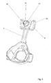
- FIGS. 1 and 1a show a patient interface (1).
- the patient interface (PI) has a mask body (2) on which the breathing gas hose, not shown, is connected to the PI via a ball joint (4) and a rotary sleeve (4a).
- the mask body (2) has as a seal relative to the patient's face a sealing element (3) in the form of a mask bead with a lip seal.
- the fixation in the region of the head of a patient can be done via a hood or headband (20).
- the Bandungsenden (22) of the hood or headband are on the one hand on receiving devices (5) in the cheek area and on the other via receptacles (6) in the forehead area releasably attached to the PI.
- the banding ends (22) are guided through the receptacles (6) and fixed to the harness via a Velcro connection (21).
- the receptacles (6) have a slot for introducing the harness.
- To support the patient interface (1) in the region of the forehead of the patient is a support body (7) with a forehead support pad (8).
- the support body (7) engages in the horizontal receptacle (2a) of the mask body (2).
- FIG. 2 shows that the support body (7) of the forehead support patient side has a forehead pad (8), which is made of a skin-friendly silicone and can also be equipped with a gel filling.
- a cylindrical guide (10) for receiving the spring element (9, 9 ') is a cylindrical guide (10) (see Fig. 3 ).
- the spring element (9) is inserted into the receptacle (10), in the bottom of an additional opening (14) is arranged, in which the spring element by a mushroom-shaped thickening (9a) and a circumferential undercut (9b) is held, so that the spring element (9) can not be lost during disassembly or daily cleaning of the mask.
- a compression spring (9 ') a comparable fuse can be provided.
- the spring element can also be arranged externally in all exemplary embodiments, for example as a forehead support pad.
- the spring element can be used as elastomer spring (9) (see Fig. 5 . 9 . 13 and 14 ) made of an elastomer such as silicone or TPE or various elastomers which are interconnected or alternatively be designed as a compression spring (9 ') made of metal such as stainless steel or plastic such as POM.
- a compression spring made of POM can be an inexpensive alternative to the compression spring made of stainless steel.
- the spring element (9, 9 ') presses together more or less firmly within the support body and presses the forehead support pad on the forehead of the user and thus always provides the optimal patient-equitable distance of the patient interfaces. Even if the patient changes his position during sleep, the spring element (9, 9 ') compensates the change again.
- the spring force of the spring element (9, 9 ') and the force of the forehead rest pad (8) can be designed so that when tightening the harness first the forehead pad (8) the shape of the user's face or the user's forehead adapts and only then the spring force of the spring element (9, 9 ') acts.
- the spring forces of spring element (9, 9 ') and forehead support pad (8) can also be the same. It is also possible to carry out the spring force of the spring element (9, 9 ') less than the forehead support pad (8).
- FIG. 3 shows that the cylindrical guide (10) on the outside lugs (12), which - due to the slots (13) in the guide (10) - are arranged on webs (12a).
- the webs (12a) are slightly resilient and engage with the lugs (12) during assembly of the support body in the receiving areas (17) of the likewise cylindrically executed recording of the support body (2a) and lock there. This prevents latching that the forehead support can slip out unintentionally.
- For torsion-proof mounting are outside of the cylindrical spring seat (10) guide elements (11) which engage in corresponding inner guide grooves (16) of the receptacle (2a) and are guided there.
- FIG. 4 shows the cylindrical receptacle (2a), which has at the end of a contact surface (15) for the spring element (9, 9 ').
- the spring travel (24) is limited by the contact surface (15) and the selected length of the receiving areas (17).
- the guide (10) slides telescopically in the receiving area (17), wherein the spring element is completely covered by both.
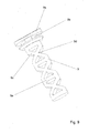
- FIG. 5 shows the spring element as an elastomeric spring (9).
- the Elastomer spring (9) gets its function through the X-shaped arrangement of struts (9c) and the choice of material.
- the angle in the X-shaped spring structure changes and the spring element becomes shorter.
- Free cuts (9d) in the X-shaped struts and the braces (9d) disposed between the X-s prevent deformation of the elastomeric spring (9) under pressure.
- the here triangular cutouts (9h) release a spring space.
- the spring characteristic can be determined by the geometry and shape of such free cuts (9h).
- FIG. 6 shows the structure in an exploded view.
- the FIGS. 7 to 9 show the corresponding items.
- the difference to the first variant is the elastomer spring (9), which is not held in the opening (14) in the support body (7) in this embodiment, but with its thickening (9a) and an undercut (9b) in the opening (18) of the forehead support receptacle (2a) is held.
- the elastomeric spring (9) from the front into the opening (18) of the Stirn sapnfact (2a) is inserted and pulled so far until the surface (15) in the undercut (9b).
- Fig. 10 shows a further embodiment for positioning a forehead support of a patient interface (1) by means of a spring element (9).
- the corresponding items are in the FIGS. 11 to 13 shown.
- the spring element (9) by means of a tab (9a) and an undercut (9b) in the receiving area (2b) of the receptacle (2a) is knotted.
- the spring element (9) has at the opposite end a centering element (9f) which is inserted into the opening (14) in the contact surface (19) of the support body (7) and a lateral movement or slippage of the spring element (9) in prevents the support body.
- the connecting webs (2c) between the mask body (2) and receiving area of the forehead support (2a) are designed so that they preferably make compression possible and thereby widen the receiving area (2a) and allow the mounting of the support body (7).
- the two connecting webs (2c) are pressed together and the supporting body in the opening of the receptacle (2a) clicked.
- the centering element (9f) of the spring element (9) must be correctly positioned in the opening (14).
- a torsion-securing of the support body (7) is ensured by guide elements in the form of a shoulder (11) on the circumference of the spring element receptacle (10) of the support body (7) and chamfers (2d) in the receptacle (2a).
- the tab (10a) on the support body (7) which is in the assembled state before receiving the support body (2a), there forms a stop in the direction of the patient.
- the displacement of the support body is limited by the abutment of the spring element (9) in the support body (7) and the length of the spring element receptacle (10) on the support body.
- the minimum adjustment point of the support body (7) to the front of the patient is reached when the tab (10a) rests against the front of the receptacle of the support body (2a).
- the maximum adjustment point of the support body (7) is reached when the receptacle (2a) rests against the support body (7).
- FIG. 13 shows the spring element as an elastomeric spring (9).
- the elastomer spring (9) has an axis (23) in its longitudinal direction. A force is always applied in the direction of the axis (23)
- the elastomeric spring (9) obtains their function by the arrangement of struts (9c) and free cuts (9h, 9i).
- the here different cutouts (9h, 9i) each form a spring chamber.
- geometry is chosen so that the cutout (9i) is softer and thus springs in when force acts on the spring element first.
- the free cut (9h) is harder because of its deviating from free cut (9i) geometry and therefore springs only after the free cut (9i) fully on.
- the spring characteristic can be determined by the geometry and shape of such free cuts (9h, 9i).
- FIG. 14 and Fig. 14a show the spring element which perpendicular to the axis (23) a first portion (9h), here by the free cut as a quadrangular geometric recess, with a first property, which is designed here as a higher spring constant or as a harder section.
- Ortsfern to the first Subarea is a second subarea (9i), here formed by the cutout as a triangular geometric recess (with a rounded base), which has a second property.
- the second property is formed here as a lower spring constant, as in the first portion, or as a softer portion of the spring element.
- FIG. 14 shows the spring element in a side view with the axis (23) which divide the spring element into an upper (9o) and a lower (9u) half.
- the upper (9o) and the lower (9u) half of the spring element here represent a first portion and a second portion. Relative to the axis, the upper half is designed differently than the lower half.
- the spring element is thus not symmetrical.
- the spring element has, perpendicular to the axis (23), a first partial area (9o) with a first property and perpendicular to the first partial area and to the axis (23) a second partial area (9u) having a second property.
- elevated x-shaped structures can be seen in the first subregion (9o), which make the spring element relatively stiffer here than in the second subregion (9u).
- the spring element bends down when force is applied in the direction of the axis (23) towards the second sub-area (9u).
- This is used in the installation position of the spring element in the receptacle (2a, 10).
- the second portion (9u) is arranged so that it can be supported on the wall of the receptacle of the spring element.
- the first portion (9o) can thus be designed accessible from the outside and without guidance by receiving the spring element. This offers advantages in cleaning the PI. If one also considers the partial regions (9h, 9i), the spring element has at least two partial regions. In the present case, the spring element has at least four partial regions (9h, 9i, 9o, 9u).
- FIGS. 15a and 15b show the adjustment or spring travel (24) of the support body (7) which is bounded by the stop (10 a).
- the spring element which perpendicular to the axis (23) a first portion (9h), here by the cut as a quadrangular geometric recess, with a first property, here as a higher spring constant or as a harder section is trained.
- a second subarea (9i) Remote from the first subarea is a second subarea (9i), here formed by the cutout as a triangular geometric recess (with a rounded base), which has a second property.
- the second property is formed here as a lower spring constant, as in the first portion, or as a softer portion of the spring element.
- the first and second partial regions of the spring element can also be opposite each other, wherein the first partial region has a higher rigidity or spring constant than the second partial region.
- a partial area can have a higher rigidity or spring constant due to geometric structures (such as ribbing, contour, open contour and closed contour).
- a partial area can have an increased rigidity or spring constant due to different materials (for example different shore hardnesses associated with the 2K process, in the area of Shore A 20-80).
- a partial area can have a higher rigidity or spring constant due to different wall thicknesses.
- the restoring force of the spring element (9, 9 ') and the restoring force of the forehead pad (8) are designed so that when applying / tightening the harness of the patient interface (1) first the forehead pad (8 ) Adjusts the shape of the user's face or the user's forehead and only then with increasing tightening force of the harness, the spring element (9, 9 ') is successively compressed. The user thus determines the tightening force of the harness, which he sets himself and thus determines the position of the patient interface relative to the forehead and thus the inclination of the patient interface on the face.
- the restoring force of the spring element (9, 9 ') and the restoring force of the forehead support pad (8) to be designed approximately the same or the restoring force of the forehead support pad (8) to be designed so that first the spring element is compressed.
- the spring element (8, 9, 9 ') is formed by the Stirnauflagepolster. Also according to the invention provided that the spring element (8, 9, 9 ') has different spring properties.
- the special advantage for the user is the infinitely fine adjustment resulting from the automatic adjustment of the forehead rest.
- it can also be provided at least one latching step, but can be overcome by additional force entry.
- a narrowly defined adjustment range which substantially corresponds to the travel, for the support body: is sufficient to cover approximately 90% of the patient's faces.
- the spring travel (24) of the spring element (8, 9, 9 ⁇ ) is therefore in all variants between 5 mm and 30 mm, 7 mm and 17 mm, preferably 8 mm to 15 mm, particularly preferably 9 mm to 14 mm.
- the spring travel of the spring element (9, 9 ⁇ ) can also be 12 mm.
- a narrowly defined spring constant of the spring element is sufficient to provide about 90% of the patients an accurately fitting and comfortable support.
- the spring constant of the spring element (8, 9, 9 ') is in the range between 0.1 to 2.0 N / mm, preferably 0.1 to 1.0 N / mm or even 0.1 to 0.5 N. / mm is also an area at 0.15 - 0.3 N / mm is being considered.
Abstract
Description
- Die Erfindung betrifft eine Vorrichtung zur Positionierung eines Patienten Interfaces am Kopf des Anwenders.
- Patienten Interfaces dienen dazu, vom Beatmungsgerät bereitgestelltes Atemgas an den Patienten abzugeben. Patienten Interfaces können in unterschiedlichen Ausführungsformen beispielsweise Nasal- oder Vollgesichtsmasken realisiert sein. Das Patienten Interface ist typischerweise über einen Atemgasschlauch mit dem Beatmungsgerät verbunden und wird am Kopf des Anwenders fixiert.
- Da das Patienten Interface stunden-, bzw. nächtelang vom Patienten getragen werden muss, sind hohe Anforderungen an den Tragekomfort gestellt.
- Neben der genauen Passform des Patienten Interfaces ist die Befestigung und Fixierung am Kopf des Anwenders wichtig um unangenehme Druckstellen und Undichtigkeiten bzw. Leckagen zu vermeiden.
- Zur Gewährleistung einer sicheren Positionierung des Patienten Interfaces im Bereich des Gesichtes eines Patienten, sowie der Verringerung der Kräfte die auf das Gesicht wirken, werden Patienten Interfaces mit Stirnstützen benutzt. Derartige Stirnstützen sind für den Patienten aber oft zu kompliziert und meist nur aufwendig einstellbar.
- Die bisher auf dem Markt verfügbaren Stirnstützen sind oftmals mit komplizierten Verstellmechanismen versehen und teilweise nicht selbsterklärend.
Der Anwender muss sich nach der Demontage - die zur Reinigung seiner Maske notwendig ist - die Rastposition der Stirnstütze merken und immer wieder erneut einstellen. - Diese Erfindung betrifft Verstellvorrichtung für ein Patienten Interface welche eine genaue, einfache Positionierung im Gesicht eines Patienten gewährleistet.
- Aufgabe der vorliegenden Erfindung ist es, eine Verstellvorrichtung für ein Patienten Interface anzugeben welche eine einfache Positionierung des Patienten Interfaces ermöglicht und der Tragekomfort des Patienten Interfaces verbessert.
- Realisiert wird die Aufgabe durch folgende Erfindungsgedanken: Verstellvorrichtung für ein Patienten Interface, welches mittels einer Kopfbänderung am Kopf des Patienten fixiert wird, mit einem Stützkörper und zumindest einem Federelement wobei das Patienten Interface zumindest eine Bänderungs-Aufnahme aufweist und die Anzugskraft der Kopfbänderung über die Bänderungs-Aufnahme auf das Federelement übertragen wird, sodass das Federelement komprimiert wird.
- Die Verstellvorrichtung ist auch dadurch gekennzeichnet, dass der Stützkörper zumindest teilweise in eine horizontale Aufnahme des Maskenkörpers eingreift.
- Die Verstellvorrichtung ist auch dadurch gekennzeichnet, dass eine Aufnahme für das Federelement im Bereich der Aufnahme und/oder im Stützkörper angeordnet ist.
- Die Verstellvorrichtung ist auch dadurch gekennzeichnet, dass das Federelement im montierten Zustand teilweise in die Aufnahme und teilweise in die Führung eintaucht und damit über die gesamte Länge überdeckt ist.
- Die Verstellvorrichtung ist auch dadurch gekennzeichnet, dass die Führung außen Nasen aufweist, die auf Stegen federnd angeordnet sind und mit den Nasen bei der Montage der Stützkörper in den Aufnahmebereich der horizontalen Aufnahme greift und dort verrastet.
- Die Verstellvorrichtung ist auch dadurch gekennzeichnet, dass sich zur verdreh-sicheren Montage außen an der Federaufnahme Führungselemente befinden, die in entsprechende innenliegende Führungsnuten der Aufnahme greifen.
- Die Verstellvorrichtung ist auch dadurch gekennzeichnet, dass die zylindrische Aufnahme am Ende eine Anlagefläche für das Federelement aufweist und der Federweg durch diese Anlagefläche und die Länge der Aufnahmebereiche begrenzt ist.
- Die Verstellvorrichtung ist auch dadurch gekennzeichnet, dass das Federelement zumindest teilweise in die Öffnung der Stirnstützenaufnahme eingeführt ist und die Fläche im Hinterschnitt liegt und so in der Öffnung der Stirnstützenaufnahme gehalten wird.
- Die Verstellvorrichtung ist auch dadurch gekennzeichnet, dass die zylindrische Führung des Stützkörpers über das Federelement geführt ist und mit den Nasen in dem Aufnahmebereich der Stirnstützenaufnahme verrastet.
- Die Verstellvorrichtung ist auch dadurch gekennzeichnet, dass das Federelement an der Anlagefläche in dem Stützkörper anliegt und der Federweg durch die Anlagefläche und die gewählte Länge der Aufnahmebereiche begrenzt wird.
- Die Verstellvorrichtung ist auch dadurch gekennzeichnet, dass das Federelement X-förmig angeordnete Streben aufweist.
- Die Verstellvorrichtung ist auch dadurch gekennzeichnet, dass die Federelementkonstante des Federelementes im Bereich zwischen 0,1 - 2,0 N/mm und liegt.
- Die Verstellvorrichtung ist auch dadurch gekennzeichnet, dass die Federelementkonstante im Bereich zwischen 0,1 - 1,0 N/mm liegt.
- Die Verstellvorrichtung ist auch dadurch gekennzeichnet, dass Kennlinie des Federelementes annähernd linear ist.
- Die Verstellvorrichtung ist auch dadurch gekennzeichnet, dass die Kennlinie des Federelementes durch Verwendung unterschiedlicher Elastomermaterialien mehrstufig ist.
- Die Verstellvorrichtung ist auch dadurch gekennzeichnet, dass Kennlinie des Federelementes durch Verwendung unterschiedlicher Geometrien oder geometrischer Aussparungen (entlang der Achse oder quer zur Achse) innerhalb des Federelementes mehrstufig ist.
- Die Verstellvorrichtung ist auch dadurch gekennzeichnet, dass das Federelement einen Federweg im Bereich 5 mm bis 30 mm bereitstellt.
- Die Verstellvorrichtung ist auch dadurch gekennzeichnet, dass das Federelement einen Federweg im Bereich 7 mm bis 20 mm bereitstellt.
- Die Verstellvorrichtung ist auch dadurch gekennzeichnet, dass Federelement in einem Teilbereich nicht von den Führungselementen umschlossen ist und so der Reinigung zugänglich ist.
- Die Verstellvorrichtung ist auch dadurch gekennzeichnet, dass Federelement eine Achse aufweist in deren Richtung die Feder gestaucht wird.
- Die Verstellvorrichtung ist auch dadurch gekennzeichnet, dass die Achse der Feder im Wesentlichen senkrecht zur Stirn des Anwenders orientiert ist.
- Die Verstellvorrichtung ist auch dadurch gekennzeichnet, dass das Federelement senkrecht zur Achse einen ersten Teilbereich mit einer ersten Eigenschaft (beispielsweise Geometrie oder Elastizität) und senkrecht zum ersten Teilbereich und zur Achse einen zweiten Teilbereich mit einer zweiten Eigenschaft aufweist.
- Die Verstellvorrichtung ist auch dadurch gekennzeichnet, dass die erste Eigenschaft ungleich der zweiten Eigenschaft ist.
- Die Verstellvorrichtung ist bevorzugt auch dadurch gekennzeichnet, dass das Federelement einen ersten und einen zweiten Teilbereich aufweist, die einander gegenüberliegen wobei der erste Teilbereich eine höhere Steifigkeit aufweist als der zweite Teilbereich.
- Die Verstellvorrichtung ist auch dadurch gekennzeichnet, dass ein Teilbereich durch geometrische Strukturen (wie beispielsweise Verrippung, offene oder geschlossene Kontur) eine höhere Steifigkeit aufweist.
- Die Verstellvorrichtung ist auch dadurch gekennzeichnet, dass ein Teilbereich durch unterschiedliche Materialien (welche beispielsweise im 2K-Verfahren verbunden sind und beispielsweise unterschiedliche Shorehärten im Bereich A 20 - 80 aufweisen) eine erhöhte Steifigkeit aufweist.
- Die Verstellvorrichtung ist auch dadurch gekennzeichnet, dass ein Teilbereich durch unterschiedliche Wandstärken eine höhere Steifigkeit aufweist.
- Die Erfindung umfasst auch eine Verstellvorrichtung für ein Patienten Interface, welches mittels einer Kopfbänderung am Kopf des Patienten fixiert wird, mit einem Stützkörper und zumindest einem Federelement dadurch gekennzeichnet, das Federelement eine Achse aufweist, in deren Richtung das Federelement gestaucht wird, und wobei das Federelement senkrecht zur Achse eine ersten Teilbereich mit einer ersten Eigenschaft und ortsverschieden zum ersten Teilbereich einen zweiten Teilbereich mit einer zweiten Eigenschaft aufweist.
- Die Erfindung bezieht sich auch auf eine Verstellvorrichtung für ein Patienten Interface welches mittels einer Kopfbänderung am Kopf des Patienten fixiert wird, mit einem Stützkörper und zumindest einem Federelement dadurch gekennzeichnet, dass die Federelementkonstante des Federelementes im Bereich zwischen 0,1 - 2,0 N/mm und liegt.
- Die Erfindung bezieht sich auch auf eine Verstellvorrichtung für ein Patienten Interface welches mittels einer Kopfbänderung am Kopf des Patienten fixiert wird, mit einem Stützkörper und zumindest einem Federelement dadurch gekennzeichnet, dass das Federelement einen Federweg im Bereich 5 mm bis 30 mm bereitstellt.
- Die Erfindung bezieht sich auch auf ein Federelement für ein Patienten Interface mit einer Achse dadurch gekennzeichnet, dass das Federelement senkrecht zur Achse eine ersten Teilbereich mit einer ersten Eigenschaft und ortsverschieden zum ersten Teilbereich einen zweiten Teilbereich mit einer zweiten Eigenschaft aufweist.
- Erfindungsgemäß wird auch eine Verstellvorrichtung für ein Patienten Interface, welches mittels einer Kopfbänderung am Kopf des Patienten fixiert wird, vorgeschlagen mit einem Stützkörper und einer Aufnahme für den Stützkörper wobei ein Federelement zwischen Stützkörper und Aufnahme angeordnet ist und Bänderungs-Aufnahmen die Anzugskraft der Kopfbänderung zumindest teilweise auf das Federelement übertragen.
- Die Vorrichtung ist auch dadurch gekennzeichnet, dass das Federelement eine stufenlose Verstellung ermöglicht.
- Die Vorrichtung ist auch dadurch gekennzeichnet, dass das Federelement einen Federweg im Bereich 7 mm bis 17 mm bereitstellt.
- Die Vorrichtung ist auch dadurch gekennzeichnet, dass das Federelement einen Federweg im Bereich 7 mm bis 20 mm bereitstellt.
- Die Vorrichtung ist auch dadurch gekennzeichnet, dass der Stützkörper zumindest teilweise in die horizontale Aufnahme des Maskenkörpers eingreift.
- Die Vorrichtung ist auch dadurch gekennzeichnet, dass der Stützkörper zumindest teilweise über die horizontale Aufnahme des Maskenkörpers greift.
- Die Vorrichtung ist auch dadurch gekennzeichnet, dass die Rückstellkraft des Federelementes und die Rückstellkraft des Stirnauflagepolsters so ausgelegt sind, dass sich beim Anziehen der Bänderung zuerst das Stirnauflagepolster der Form der Anwenderstirn anpasst und erst dann das Federelement komprimiert wird.
- Die Vorrichtung ist auch dadurch gekennzeichnet, dass das Federelement im Bereich Aufnahme fixiert wird.
- Die Vorrichtung ist auch dadurch gekennzeichnet, dass das Federelement im Bereich der zylindrischen Führung im Stützkörper fixiert wird.
- Die Vorrichtung ist auch dadurch gekennzeichnet, dass das Federelement im montierten Zustand teilweise in die Aufnahme und teilweise in die zylindrische Führung eintaucht und damit vollständig überdeckt ist.
- Die Vorrichtung ist auch dadurch gekennzeichnet, dass das Federelement im montierten Zustand teilweise in die Aufnahme und teilweise in die zylindrische Führung eintaucht und damit teilweise überdeckt ist.
- Die Vorrichtung ist auch dadurch gekennzeichnet, dass die zylindrischen Führung zumindest teilweise in die Aufnahme eintaucht und dort lösbar fixiert ist.
- Die Vorrichtung ist auch dadurch gekennzeichnet, dass die zylindrische Führung außen Nasen aufweist, die auf Stegen federnd angeordnet sind und mit den Nasen bei der Montage der Stützkörper in die Aufnahmebereiche der zylindrischen horizontalen Aufnahme greifen und dort leicht verrasten.
- Die Vorrichtung ist auch dadurch gekennzeichnet, dass sich zur verdrehsicheren Montage außen an der zylindrischen Federaufnahme Führungselemente befinden, die in entsprechende innenliegende Führungsnuten der Aufnahme greifen und dort geführt werden.
- Die Vorrichtung ist auch dadurch gekennzeichnet, dass die zylindrische Aufnahme am Ende eine Anlagefläche für das Federelement aufweist und der Federweg durch diese Anlagefläche und die Länge der Aufnahmebereiche begrenzt ist.
- Die Vorrichtung ist auch dadurch gekennzeichnet, dass das Federelement zumindest teilweise in die Öffnung der Stirnstützenaufnahme eingeführt ist und die Fläche im Hinterschnitt liegt und so in der Öffnung der Stirnstützenaufnahme gehalten wird.
- Die Vorrichtung ist auch dadurch gekennzeichnet, dass die zylindrische Führung der Stützkörper über das Federelement geführt und mit den Nasen in den Aufnahmebereichen der Stirnstützenaufnahme verrastet.
- Die Vorrichtung ist auch dadurch gekennzeichnet, dass das Federelement an der Anlagefläche in dem Stützkörper anliegt und der Federweg durch die Anlagefläche und die gewählte Länge der Aufnahmebereiche begrenzt wird.
- Die Vorrichtung ist auch dadurch gekennzeichnet, dass die Elastomer-Feder ihre Funktion als Druckfeder durch die X-förmige Anordnung von Streben und die Auswahl des Materials erhält.
- Die Vorrichtung ist auch dadurch gekennzeichnet, dass das Federelementkonstante im Bereich zwischen 0,1 - 2,0 N/mm liegt. Bevorzugt im Bereich 0,1 - 1,0 N/mm, besonders bevorzugt im Bereich 0,1 - 0,8 N/mm oder auch im Bereich 0,1 - 0,5 N/mm.
- Die Federkennlinie beschreibt die Abhängigkeit der Federkraft F vom Federweg. Ein Federelement mit einer linearen Federkennlinie hat eine Federkonstante. Denkbar sind auch progressive oder degressive Kennlinien. Die Federkonstante entspricht der Steifigkeit des Federelementes, dividiert durch die Länge. Die Steifigkeit ist der Widerstand eines Federleementes gegen elastische Verformung durch eine Kraft. Bei Verwendung zweier unterschiedlicher Materialien oder Geometrien können zwei unterschiedliche Federkonstanten in einem Federelement realisiert werden, mit jeweils unterschiedlicher Kennlinie und/oder Steifigkeit. Bei elastomeren Federelementen können solche Eigenschaften im 2k Verfahren hergestellt werden.
- Je nach Anzugskraft der Bänderung der Kopfbänderung bzw. der Kopfhaube und der Form des Anwendergesichts- bzw. der Anwenderstirn drückt sich das Federelement innerhalb der Stirnstütze mehr oder weniger fest zusammen und drückt das Stirnpolster auf die Stirn des Anwenders und bietet so immer den patientengerechten Abstand des Patienten Interfaces.
- Die folgenden Figuren zeigen Ausführungsbeispiele eines Patienten Interfaces mit einem Stützkörper der einleitenden Art.
- Fig.1:
- Patienten Interface
- Fig.1a:
- Patienten Interface mit Bänderung
- Fig.2:
- Explosionsdarstellung der Stirnstützenverstellung, Variante 1
- Fig.3:
- Stirnauflage
- Fig.4:
- Maskenkörper
- Fig.5:
- Elastomer-Feder
- Fig.6:
- Explosionsdarstellung der Stirnstützenverstellung, Variante 2
- Fig.7:
- Stirnauflage
- Fig.8:
- Maskenkörper
- Fig.9:
- Elastomer-Feder
- Fig.10:
- Explosionsdarstellung der Stirnstützenverstellung, Variante 3
- Fig.11
- Stirnauflage
- Fig.12
- Maskenkörper
- Fig.13
- elastomeres Federelement
- Fig.14
- Federelement, Ansicht seitlich
- Fig.14a
- Federelement, Ansicht von oben
- Fig.15a,b
- Verstellweg Federelement
- Die
Figuren 1 und1a zeigen ein Patienten Interface (1). Das Patienten Interface (PI) weist einen Maskenkörper (2) auf, an dem über ein Kugel-Gelenk (4) und eine Drehhülse (4a) der nicht dargestellte Atemgasschlauch mit dem PI verbunden wird. Der Maskenkörper (2) weist als Abdichtung relativ zum Gesicht des Patienten ein Dichtelement (3) in Form eines Maskenwulstes mit einer Lippendichtung auf. Die Fixierung im Bereich des Kopfes eines Patienten kann über eine Kopfhaube oder Kopfbänderung (20) erfolgen. Die Bänderungsenden (22) der Kopfhaube bzw. Kopfbänderung werden zum Einen über Aufnahmevorrichtungen (5) im Wangenbereich und zum Anderen über Aufnahmen (6) im Stirnbereich lösbar an dem PI befestigt. Dazu werden die Bänderungsenden (22) durch die Aufnahmen (6) geführt und über eine Klettverbindung (21) an der Bänderung fixiert. Die Aufnahmen (6) weisen einen Schlitz zum Einführen der Bänderung auf. Zur Abstützung des Patienten Interfaces (1) im Bereich der Stirn des Patienten dient ein Stützkörper (7) mit einem Stirnauflagepolster (8). Der Stützkörper (7) greift in die horizontale Aufnahme (2a) des Maskenkörpers (2). -
Figur 2 zeigt, dass der Stützkörper (7) der Stirnstütze patientenseitig ein Stirnpolster (8) aufweist, welches aus einem hautfreundlichen Silikon hergestellt ist und auch mit einer Gelfüllung ausgestattet sein kann. Zur Aufnahme des Federelementes (9, 9') dient eine zylindrische Führung (10) (sieheFig. 3 ). Das Federelement (9) wird in die Aufnahme (10) gesteckt, in dessen Boden eine zusätzliche Öffnung (14) angeordnet ist, in der das Federelement durch eine pilzköpfige Verdickung (9a) und einen umlaufenden Hinterschnitt (9b) gehalten wird, sodass das Federelement (9) bei der Demontage bzw. zur täglichen Reinigung der Maske nicht verloren gehen kann. Für eine Druckfeder (9') kann eine vergleichbare Sicherung vorgesehen sein.
Eine automatische Verstellung / Einstellung des Stützkörpers (7) erfolgt mittels einem innenliegenden Federelement (9, 9') in dem Stützkörper. Das Federelement kann in allen Ausführungsbeispielen auch außenliegend, beispielsweise als Stirnauflagepolster, angeordnet sein. Das Federelement kann als Elastomer-Feder (9) (sieheFig. 5 ,9 ,13 und14 ) aus einem Elastomer wie beispielsweise Silikon oder TPE oder aus verschiedenen Elastomeren die miteinander verbunden sind oder alternativ als Druckfeder (9') aus Metall wie aus Edelstahl oder aus Kunststoff wie POM ausgeführt sein. Eine Druckfeder aus POM kann eine preiswerte Alternative zur Druckfeder aus Edelstahl sein.
Je nach Anzugskraft der Kopfbänderung drückt sich das Federelement (9, 9') innerhalb des Stützkörpers mehr oder weniger feste zusammen und drückt das Stirnauflagepolster auf die Stirn des Anwenders und bietet so immer den optimalen patientengerechten Abstand des Patienten Interfaces. Selbst wenn der Patient im Schlaf seine Lage verändert, gleicht das Federelement (9, 9') die Veränderung wieder aus.
Die Federkraft des Federelementes (9, 9') und die Kraft des Stirnauflagepolsters (8) können so ausgelegt sein, dass sich beim Anziehen der Bänderung zuerst das Stirnauflagepolster (8) der Form des Anwendergesichts- bzw. der Anwenderstirn anpasst und erst dann die Federkraft des Federelementes (9, 9') wirkt. Die Federkräfte von Federelement (9, 9') und Stirnauflagepolster (8) können auch gleich sein. Es ist ebenfalls möglich die Federkraft des Federelementes (9, 9') geringer als die Stirnauflagepolsters (8) auszuführen. -
Figur 3 zeigt, dass die zylindrische Führung (10) außen Nasen (12) aufweist, die - bedingt durch die Schlitze (13) in der Führung (10) - auf Stegen (12a) angeordnet sind. Die Stege (12a) sind leicht federnd und greifen mit den Nasen (12) bei der Montage der Stützkörper in die Aufnahmebereiche (17) der ebenfalls zylindrisch ausgeführten Aufnahme der Stützkörper (2a) ein und verrasten dort. Diese verhindert Verrastung, dass die Stirnstütze ungewollt herausrutschen kann. Zur verdrehsicheren Montage befinden sich außen an der zylindrischen Federaufnahme (10) Führungselemente (11), die in entsprechenden innenliegende Führungsnuten (16) der Aufnahme (2a) greifen und dort geführt werden. -
Figur 4 zeigt die zylindrische Aufnahme (2a), welche am Ende eine Anlagefläche (15) für das Federelement (9, 9') aufweist. Der Federweg (24) wird durch die Anlagefläche (15) und die gewählte Länge der Aufnahmebereiche (17) begrenzt. In einem Ausführungsbeispiel gleitet die Führung (10) teleskopierend in dem Aufnahmebereich (17), wobei das Federelement vollständig von beiden überdeckt ist. -
Figur 5 zeigt das Federelement als Elastomer-Feder (9). Die Elastomer-Feder (9) erhält ihre Funktion durch die X-förmige Anordnung von Streben (9c) und die Auswahl des Materials. Bei Druck auf das Federelement (9) verändert sich der Winkel in der X-förmigen Federstruktur und das Federelement wird kürzer. Freischnitte (9d) in den X-förmigen Streben und die zwischen den X-en angeordneten Verstrebungen (9d) verhindern ein Verformen der Elastomer-Feder (9) bei Druck. Die hier dreieckigen Freischnitte (9h) geben einen Federraum frei. Grundsätzlich kann durch die Geometrie und Form solcher Freischnitte (9h) die Federeigenschaft mitbestimmt werden. -
Fig. 6 zeigt den Aufbau in einer Explosionsdarstellung. DieFiguren 7 bis 9 zeigen die entsprechenden Einzelteile. Der Unterschied zur 1. Variante ist die Elastomer-Feder (9), die in dieser Ausführungsform nicht in der Öffnung (14) im Stützkörper (7) gehalten wird, sondern mit seiner Verdickung (9a) und einem Hinterschnitt (9b) in der Öffnung (18) der Stirnstützenaufnahme (2a) gehalten wird. Zur Montage wird die Elastomer-Feder (9) von vorne in die Öffnung (18) der Stirnstützenaufnahme (2a) eingeführt und so weit gezogen, bis die Fläche (15) im Hinterschnitt (9b) liegt. Danach wird die zylindrische Führung (10) der Stützkörper (7) über das Federelement geführt und verrastet ebenfalls, wie bereits in Variante 1 beschrieben, mit den Nasen (12) in den Aufnahmebereichen (17) der Stirnstützenaufnahme (2a). Die Elastomer-Feder (9) liegt in dieser Variante an der Anlagefläche (19) in dem Stützkörper (7) an. Der Federweg (24) wird durch die Anlagefläche (19) und die gewählte Länge der Aufnahmebereiche (17) begrenzt. -
Fig. 10 zeigt eine weitere Ausführungsform zur Positionierung einer Stirnauflage eines Patienten Interfaces (1) mittels eines Federelementes (9). Die entsprechenden Einzelteile sind in denFiguren 11 bis 13 dargestellt. Zur Montage wird das Federelement (9) mittels einer Lasche (9a) und einem Hinterschnitt (9b) in den Aufnahmebereich (2b) der Aufnahme (2a) eingeknüpft. Das Federelement (9) weist an dem entgegengesetzten Ende ein Zentrierelement (9f) auf, das in die Öffnung (14) in der Anlagefläche (19) des Stützkörpers (7) eingeführt wird und ein seitliches Bewegen bzw. Verrutschen des Federelementes (9) in dem Stützkörper verhindert.
Die Verbindungsstege (2c), die zwischen Maskenkörper (2) und Aufnahmebereich der Stirnstütze (2a) sind so gestaltet, dass sie vorzugsweise ein Zusammendrücken möglich machen und dadurch den Aufnahmebereich (2a) aufweiten und die Montage des Stützkörpers (7) ermöglichen.
Zur Montage werden die die beiden Verbindungsstege (2c) zusammengedrückt und der Stützkörper in die Öffnung der Aufnahme (2a) geklickt. Dabei muss das Zentrierelement (9f) des Federelementes (9) in der Öffnung (14) richtig positioniert sein. Eine Verdreh-Sicherung des Stützkörpers (7) wird durch Führungselemente in Form eines Absatzes (11) am Umfang der Federelementaufnahme (10) des Stützkörpers (7) und Fasen (2d) in der Aufnahme (2a) gewährleistet.
Die Lasche (10a) an dem Stützkörper (7), die im montierten Zustand vor der Aufnahme der Stützkörper (2a) liegt, bildet dort einen Anschlag in Richtung zum Patienten. Der Verstellweg des Stützkörpers wird durch die Anlage des Federelementes (9) in dem Stützkörper (7) und die Länge der Federelementaufnahme (10) an dem Stützkörper begrenzt. Der minimale Verstellpunkt des Stützkörpers (7) zur Stirn des Patienten ist erreicht, wenn die Lasche (10a) vorne an der Aufnahme des Stützkörpers (2a) anliegt. Der maximale Verstellpunkt des Stützkörpers (7) ist erreicht, wenn die Aufnahme (2a) an dem Stützkörper (7) anliegt. -
Figur 13 zeigt das Federelement als Elastomer-Feder (9). Die Elastomer-Feder (9) hat eine Achse (23) in ihrer Längsrichtung. Eine Kraftbeaufschlagung erfolgt immer in Richtung der Achse (23) Die Elastomer-Feder (9) erhält ihre Funktion durch die Anordnung von Streben (9c) und Freischnitten (9h, 9i). Bei Druck auf das Federelement (9) verändert sich der Winkel in den Freischnitten (9h, 9i) und das Federelement wird kürzer. Die hier unterschiedlichen Freischnitte (9h, 9i) bilden jeweils einen Federraum. Hier ist Geometrie so gewählt, dass der Freischnitt (9i) weicher ist und somit bei Krafteinwirkung auf das Federelement zuerst einfedert. Der Freischnitt (9h) ist aufgrund seiner von Freischnitt (9i) abweichenden Geometrie härter und federt daher erst nach dem Freischnitt (9i) voll ein. Grundsätzlich kann durch die Geometrie und Form solcher Freischnitte (9h, 9i) die Federeigenschaft mitbestimmt werden. -
Figur 14 undFig 14a zeigen das Federelement welches senkrecht zur Achse (23) eine ersten Teilbereich (9h), hier durch den Freischnitt als viereckige geometrische Aussparung, mit einer ersten Eigenschaft, die hier als höhere Federkonstante oder als härterer Abschnitt ausgebildet ist. Ortsfern zum ersten Teilbereich ist ein zweiter Teilbereich (9i), hier durch den Freischnitt als dreieckige geometrische Aussparung (mit gerundeter Basis), ausgebildet, der eine zweiten Eigenschaft aufweist. Die zweite Eigenschaft ist hier als geringere Federkonstante, als im ersten Teilbereich, oder als weicherer Abschnitt des Federelementes ausgebildet.
Figur 14 zeigt das Federelement in einer seitlichen Ansicht mit der Achse (23) die das Federelement in eine obere (9o) und eine untere (9u) Hälfte unterteilen. Die obere (9o) und die untere (9u) Hälfte des Federelementes stellen hier einen ersten Teilbereich und einen zweiter Teilbereich dar. Bezogen auf die Achse ist die obere Hälfte anders gestaltet als die untere Hälfte. Das Federelement ist somit nicht symmetrisch aufgebaut. Das Federelement weist senkrecht zur Achse (23) einen ersten Teilbereich (9o) mit einer ersten Eigenschaft und senkrecht zum ersten Teilbereich und zur Achse (23) einen zweiten Teilbereich (9u) mit einer zweiten Eigenschaft auf. Vorliegend sind im ersten Teilbereich (9o) erhöhte x-förmige Strukturen zu erkennen, die das Federelement hier relativ steifer machen als im zweiten Teilbereich (9u). Im zweiten Teilbereich (9u) finden sich keine Versteifungen oder Erhöhungen, weshalb sich das Federelement bei Kraftbeaufschlagung in Richtung zur Achse (23) nach unten hin zum zweiten Teilbereich (9u) durchbiegt. Dies wird genutzt bei der Einbaulage des Federelementes in die Aufnahme (2a, 10). In der Aufnahme ist der zweite Teilbereich (9u) so angeordnet, dass der sich an der Wandung der Aufnahme des Federelementes abstützen kann. Der erste Teilbereich (9o) kann somit von außen zugänglich und ohne Führung durch die Aufnahme des Federelementes gestaltet werden. Dies bietet Vorteile bei der Reinigung des PI.
Betrachtet man zusätzlich die Teilbereiche (9h, 9i), so weist das Federelement zumindest zwei Teilbereiche auf. Vorliegend weist das Federelement zumindest vier Teilbereiche (9h, 9i, 9o, 9u) auf. -
Figur 15a und 15b zeigen den Verstellweg oder Federweg (24) des Stützkörpers (7) der durch den Anschlag (10a) begrenzt ist.
Für alle Ausführungsformen der Erfindung kann gelten: Das Federelement welches senkrecht zur Achse (23) eine ersten Teilbereich (9h), hier durch den Freischnitt als viereckige geometrische Aussparung, mit einer ersten Eigenschaft, die hier als höhere Federkonstante oder als härterer Abschnitt ausgebildet ist. Ortsfern zum ersten Teilbereich ist ein zweiter Teilbereich (9i), hier durch den Freischnitt als dreieckige geometrische Aussparung (mit gerundeter Basis), ausgebildet, der eine zweiten Eigenschaft aufweist. Die zweite Eigenschaft ist hier als geringere Federkonstante, als im ersten Teilbereich, oder als weicherer Abschnitt des Federelementes ausgebildet.
Der erste und zweite Teilbereich des Federelemtes können auch einander gegenüberliegen wobei der erste Teilbereich eine höhere Steifigkeit oder Federkonstante aufweist als der zweite Teilbereich. - Ein Teilbereich kann durch geometrische Strukturen (wie beispielsweise Verrippung, Kontur, offene Kontur und geschlossene Kontur) eine höhere Steifigkeit oder Federkonstante aufweisen.
- Ein Teilbereich kann durch unterschiedliche Materialien (beispielsweise im 2K-Verfahren verbundene unterschiedliche Shorehärten, im Bereich Shore A 20 - 80) eine erhöhte Steifigkeit oder Federkonstante aufweisen.
- Ein Teilbereich kann durch unterschiedliche Wandstärken eine höhere Steifigkeit oder Federkonstante aufweisen.
- Für alle Ausführungsformen der Erfindung kann auch gelten: Die Rückstellkraft des Federelementes (9, 9') und die Rückstellkraft des Stirnauflagepolsters (8) sind so ausgelegt, dass sich beim Anlegen/Anziehen der Bänderung des Patienten Interfaces (1) zuerst das Stirnauflagepolster (8) der Form des Anwendergesichts bzw. der Anwenderstirn anpasst und erst dann mit steigender Anzugkraft der Bänderung das Federelement (9, 9') sukzessiv komprimiert wird. Der Anwender bestimmt so über die Anzugkraft der Bänderung, die er selbst einstellt und somit bestimmt, die Lage des Patienteninterface relativ zur Stirn und somit die Neigung des Patienteninterface auf dem Gesicht. Erfindungsgemäß ist es auch möglich die Rückstellkraft des Federelementes (9, 9') und die Rückstellkraft des Stirnauflagepolsters (8) etwa gleich auszulegen oder die des Rückstellkraft des Stirnauflagepolsters (8) so auszulegen, dass zunächst das Federelement komprimiert wird. Erfindungsgemäß ist auch vorgesehen, dass das Federelement (8, 9, 9') durch das Stirnauflagepolster gebildet wird. Erfindungsgemäß ist auch vorgesehen, dass das Federelement (8, 9, 9') unterschiedliche Federeigenschaften aufweist.
- Um dies zu gewährleisten sind vorteilhaft keine Raststufen vorgesehen. Der besondere Vorteil für den Benutzer ist die, aus dem automatischen Verstellen der Stirnstütze, resultierende stufenlose Feineinstellung. Es kann jedoch auch zumindest eine Raststufe vorgesehen werden, die jedoch durch zusätzlichen Krafteintrag überwunden werden kann.
- Durch das Kräftegleichgewicht zwischen der Anzugkraft der Kopfbänderung und der Rückstellkraft des Federelementes der Stirnstütze ist jederzeit eine optimale und fehlerfreie Anpassung gewährleistet, auch wenn der Patient im Schlaf seine Lage verändert.
- Überraschenderweise wurde im Rahmen der vorliegenden Erfindung festgestellt, dass bei einem Patienteninterface der erfindungsgemäßen Art ein eng definierter Verstellbereich, der im Wesentlichen dem Federweg entspricht, für den Stützkörper : ausreichend ist, um etwa 90 % der Patientengesichter abzudecken. Der Federweg (24) des Federelementes (8, 9, 9`) liegt daher bei allen Varianten zwischen 5 mm und 30 mm, 7 mm und 17 mm, bevorzugt bei 8 mm bis 15 mm, besonders bevorzugt bei 9 mm bis 14 mm. Der Federweg des Federelementes (9, 9`) kann auch bei 12 mm liegen.
Überraschenderweise wurde im Rahmen der vorliegenden Erfindung festgestellt, dass bei einem Patienteninterface der erfindungsgemäßen Art eine eng definierte Federkonstante des Federelementes ausreichend ist, um etwa 90 % der Patienten eine passgenaue und angenehme Abstützung zu bieten.
Die Federkonstante des Federelementes (8, 9, 9') liegt im Bereich zwischen 0,1 - 2,0 N/mm, bevorzugt bei 0,1 - 1,0 N/mm oder auch bei 0,1 - 0,5 N/mm auch ein Bereich bei 0,15 - 0,3 N/mm ist angedacht. -
- 1
- Patient Interface
- 2
- Maskenkörper
- 2a
- Aufnahme der Stützkörper
- 2b
- Aufnahmebereich für Feder
- 2c
- Verbindungsstege
- 2d
- Fasen
- 3
- Maskenwulst
- 4
- Schlauchkupplung
- 4a
- Drehhülse
- 5
- Aufnahmevorrichtung für Bänderung am Maskenkörper
- 6
- Bänderungs-Aufnahme Stirnstützenträger
- 7
- Stützkörper
- 8
- Stirnauflagepolster
- 9
- Federelement
- 9a
- Verdickung, Lasche an Federelement
- 9b
- Hinterschnitt an Federelement
- 9c
- X-förmige Federstruktur
- 9d
- Freischnitt
- 9e
- Streben zwischen den X-Formen
- 9f
- Zentrierelement
- 9g
- Verstärkung der X-förmigen Federstruktur
- 9h, 9i
- Teilbereiche des Federelementes
- 9o, 9u
- Teilbereiche des Federelementes
- 9'
- Federelement, Druckfeder
- 10
- Zylindrische Führung / Federaufnahme
- 10a
- Anschlaglasche
- 11
- Führungselement
- 12
- Nasen
- 12a
- Stege
- 13
- Schlitze
- 14
- Öffnung für Federelement
- 15
- Anlagefläche für Federelement in Aufnahme (2a)
- 16
- Führungsnuten
- 17
- Aufnahmebereiche
- 18
- Öffnung für Federelement in Aufnahme (2a)
- 19
- Anlagefläche für Federelement in Stützkörper (7)
- 20
- Bänderung
- 21
- Klettverbindung
- 22
- Bänderungsenden
- 23
- Achse
- 24
- Federweg
Claims (15)
- Verstellvorrichtung für ein Patienten Interface (1), welches mittels einer Kopfbänderung (20) am Kopf des Patienten fixiert wird, mit einem Stützkörper (7) und zumindest einem Federelement (9, 9`) dadurch gekennzeichnet, dass das Patienten Interface (1) zumindest eine Bänderungs-Aufnahme (5, 6) aufweist und die Anzugskraft der Kopfbänderung (20) über die Bänderungs-Aufnahme (5, 6) auf das Federelement (9, 9`) übertragen wird, sodass das Federelement (9, 9') komprimiert wird.
- Vorrichtung nach zumindest einem der vorhergehenden Ansprüche dadurch gekennzeichnet, dass das Federelement (9, 9') einen Federweg im Bereich 5 mm bis 30 mm bereitstellt.
- Vorrichtung nach zumindest einem der vorhergehenden Ansprüche dadurch gekennzeichnet, dass die Federelementkonstante des Federelementes zumindest abschnittsweise im Bereich zwischen 0,1 - 2,0 N/mm und liegt.
- Vorrichtung nach zumindest einem der vorhergehenden Ansprüche dadurch gekennzeichnet, dass Kennlinie des Federelementes annähernd linear ist.
- Vorrichtung nach zumindest einem der vorhergehenden Ansprüche dadurch gekennzeichnet, dass die Kennlinie des Federelementes durch Verwendung unterschiedlicher Elastomermaterialien und/oder unterschiedlicher Geometrien und/oder geometrischer Aussparungen innerhalb des Federelementes mehrstufig ist.
- Vorrichtung nach zumindest einem der vorhergehenden Ansprüche dadurch gekennzeichnet, dass Federelement eine Achse (23) aufweist in deren Richtung die Feder gestaucht wird und die Achse (23) im Wesentlichen senkrecht zur Stirn des Anwenders orientiert ist.
- Vorrichtung nach zumindest einem der vorhergehenden Ansprüche dadurch gekennzeichnet, dass das Federelement senkrecht zur Achse (23) eine ersten Teilbereich mit einer ersten Eigenschaft und senkrecht zum ersten Teilbereich und zur Achse (23) einen zweiten Teilbereich mit einer zweiten Eigenschaft aufweist.
- Vorrichtung nach zumindest einem der vorhergehenden Ansprüche dadurch gekennzeichnet, dass die erste Eigenschaft ungleich der zweiten Eigenschaft ist.
- Vorrichtung bevorzugt nach zumindest einem der vorhergehenden Ansprüche dadurch gekennzeichnet, dass das Federelement (9, 9') einen ersten und einer zweiten Teilbereich aufweist, die einander gegenüberliegen wobei der erste Teilbereich eine höhere Steifigkeit aufweist als der zweite Teilbereich.
- Vorrichtung bevorzugt nach zumindest einem der vorhergehenden Ansprüche dadurch gekennzeichnet, dass ein Teilbereich durch geometrische Strukturen und/oder unterschiedliche Materialien und/oder unterschiedliche Wandstärken eine höhere Steifigkeit aufweist.
- Verstellvorrichtung für ein Patienten Interface (1) bevorzugt nach einem der vorhergehenden Ansprüche dadurch gekennzeichnet, dass das Federelement eine Achse (23) aufweist, in deren Richtung das Federelement gestaucht wird, wobei das Federelement senkrecht zur Achse (23) einen ersten Teilbereich mit einer ersten Eigenschaft und ortsverschieden zum ersten Teilbereich einen zweiten Teilbereich mit einer zweiten Eigenschaft aufweist.
- Vorrichtung bevorzugt nach zumindest einem der vorhergehenden Ansprüche dadurch gekennzeichnet, dass das Federelement (9) X-förmig angeordnete Streben (9c) aufweist.
- Vorrichtung bevorzugt nach zumindest einem der vorhergehenden Ansprüche dadurch gekennzeichnet, dass der Stützkörper (7) zumindest teilweise in eine horizontale Aufnahme (2a) des Maskenkörpers (2) eingreift und das Federelement (9, 9') im montierten Zustand teilweise in die Aufnahme (2a) und teilweise in eine Führung (10) eintaucht.
- Vorrichtung bevorzugt nach zumindest einem der vorhergehenden Ansprüche dadurch gekennzeichnet, dass die Führung (10) Nasen (12) aufweist, der Stützkörper in den Aufnahmebereich (17) der horizontalen Aufnahme (2a) greift und dort verrastet.
- Federelement (9, 9') insbesondere für eine Verstellvorrichtung nach zumindest einem der vorhergehenden Ansprüche mit einer Achse (23) dadurch gekennzeichnet, dass das Federelement bezogen auf die Achse (23) einen ersten Teilbereich und ortsverschieden zum ersten Teilbereich einen zweiten Teilbereich aufweist.
Applications Claiming Priority (1)
| Application Number | Priority Date | Filing Date | Title |
|---|---|---|---|
| DE102012022355 | 2012-11-15 |
Publications (3)
| Publication Number | Publication Date |
|---|---|
| EP2732839A2 true EP2732839A2 (de) | 2014-05-21 |
| EP2732839A3 EP2732839A3 (de) | 2014-07-09 |
| EP2732839B1 EP2732839B1 (de) | 2021-05-12 |
Family
ID=49641445
Family Applications (1)
| Application Number | Title | Priority Date | Filing Date |
|---|---|---|---|
| EP13005324.2A Active EP2732839B1 (de) | 2012-11-15 | 2013-11-12 | Vorrichtung zur Positionierung eines Patienten Interfaces |
Country Status (3)
| Country | Link |
|---|---|
| US (3) | US10137272B2 (de) |
| EP (1) | EP2732839B1 (de) |
| DE (1) | DE102013018897A1 (de) |
Cited By (2)
| Publication number | Priority date | Publication date | Assignee | Title |
|---|---|---|---|---|
| EP3417898A1 (de) * | 2017-06-19 | 2018-12-26 | Löwenstein Medical Technology S.A. | Atemmaske mit kopplungselement für eine bänderung |
| EP3513828A1 (de) * | 2012-11-29 | 2019-07-24 | Löwenstein Medical Technology S.A. | Maskenwulst für ein patienteninterface |
Families Citing this family (7)
| Publication number | Priority date | Publication date | Assignee | Title |
|---|---|---|---|---|
| USD695887S1 (en) | 2010-09-10 | 2013-12-17 | Resmed Limited | Respiratory mask |
| JP6165753B2 (ja) * | 2011-11-03 | 2017-07-19 | コーニンクレッカ フィリップス エヌ ヴェKoninklijke Philips N.V. | 複数材料単一面ヘッドギア |
| DE102013018897A1 (de) * | 2012-11-15 | 2014-05-15 | Weinmann Geräte für Medizin GmbH + Co. KG | Vorrichtung zur Positionierung eines Patienten Interfaces |
| DE102014212432A1 (de) * | 2014-06-27 | 2015-12-31 | Conti Temic Microelectronic Gmbh | System zum Haltern eines Steuergeräts an einem Bauteil |
| JP6968804B2 (ja) | 2015-10-05 | 2021-11-17 | タクティル システムズ テクノロジー,インコーポレイティド | 頭部と首の圧迫治療システム |
| USD839484S1 (en) * | 2017-02-28 | 2019-01-29 | Tactile Systems Technology, Inc. | Head Garment |
| EP4079270A1 (de) | 2017-11-06 | 2022-10-26 | Tactile Systems Technology, Inc. | Kompressionskleidungssysteme |
Family Cites Families (25)
| Publication number | Priority date | Publication date | Assignee | Title |
|---|---|---|---|---|
| US3792702A (en) * | 1972-04-10 | 1974-02-19 | Ulmer & Co Soc | Harness for rapidly placing in position a device such as a respirator mask |
| DE3741731A1 (de) * | 1987-12-09 | 1989-06-22 | Wolf Woco & Co Franz J | Stossdaempferfeder |
| DE3942903C1 (de) * | 1989-12-23 | 1991-07-25 | Metzeler Gmbh, 8000 Muenchen, De | |
| US5280890A (en) * | 1992-01-22 | 1994-01-25 | Miner Enterprises, Inc. | Radial elastomer compression spring |
| DE4325913A1 (de) * | 1993-08-02 | 1995-02-09 | Clouth Gummiwerke Ag | Federkörper |
| US5868384A (en) * | 1997-04-11 | 1999-02-09 | Miner Enterprises, Inc. | Composite elastomeric spring |
| DE10105791A1 (de) * | 2001-02-07 | 2002-08-08 | Basf Ag | Federelement |
| DE10106597A1 (de) * | 2001-02-09 | 2002-08-22 | Zf Boge Gmbh | Dämpfungsfeder |
| US6612556B2 (en) * | 2001-04-30 | 2003-09-02 | Cornell Research Foundation, Inc. | Multihelical composite spring |
| CN103143098B (zh) * | 2002-09-06 | 2016-03-09 | 瑞思迈有限公司 | 呼吸面罩的前额衬垫 |
| AU2003275762A1 (en) * | 2002-11-06 | 2004-06-07 | Resmed Limited | Mask and components thereof |
| CN106110464B (zh) * | 2004-06-16 | 2019-03-12 | 瑞思迈有限公司 | 呼吸面罩组件的软垫 |
| EP3950032B1 (de) * | 2005-01-12 | 2023-10-11 | ResMed Pty Ltd | Atemmasken mit gefalteten polstern |
| US20080053446A1 (en) * | 2006-03-31 | 2008-03-06 | Tiara Medical Systems, Inc. | Adjustable cpap mask assembly |
| US9707367B2 (en) * | 2007-06-21 | 2017-07-18 | Resmed Limited | Auto-adjusting mask stabilizer |
| NZ569226A (en) * | 2007-06-22 | 2010-02-26 | Resmed Ltd | Flexible forehead support |
| ES2383221T3 (es) | 2008-06-10 | 2012-06-19 | Covidien Ag | Filtro y/o dispositivo de HME para circuitos respiratorios que comprende una trampa de condensación |
| US8176919B2 (en) * | 2009-10-28 | 2012-05-15 | Hsiner Co., Ltd. | Respiratory mask including an adjustable forehead abutment member |
| AU2011225761B2 (en) * | 2010-03-12 | 2014-09-25 | Koninklijke Philips Electronics N.V. | Patient interface device with dynamic mask adjustment |
| TWI396566B (zh) * | 2010-07-16 | 2013-05-21 | Apex Medical Corp | 陽壓呼吸面罩的可置換額墊 |
| US9700694B2 (en) | 2010-08-09 | 2017-07-11 | Koninklijke Philips N.V. | Patient interface device including a dynamic self adjustment mechanism |
| JP2015521936A (ja) * | 2012-07-11 | 2015-08-03 | コーニンクレッカ フィリップス エヌ ヴェ | 患者インターフェイス |
| DE102013018897A1 (de) * | 2012-11-15 | 2014-05-15 | Weinmann Geräte für Medizin GmbH + Co. KG | Vorrichtung zur Positionierung eines Patienten Interfaces |
| DE202013100755U1 (de) * | 2013-02-20 | 2013-03-08 | Enter Medical Corporation | Stirnauflagevorrichtung für den Gebrauch mit einer Atemmaske ohne Verstellung |
| DE202015007792U1 (de) * | 2015-11-12 | 2016-02-26 | Weinmann Geräte für Medizin GmbH + Co. KG | Vorrichtung zur Abstützung eines Patienteninterfaces am Kopf des Anwenders |
-
2013
- 2013-11-12 DE DE102013018897.0A patent/DE102013018897A1/de active Pending
- 2013-11-12 EP EP13005324.2A patent/EP2732839B1/de active Active
- 2013-11-13 US US14/078,748 patent/US10137272B2/en active Active
-
2018
- 2018-11-16 US US16/192,895 patent/US11160946B2/en active Active
-
2021
- 2021-10-25 US US17/452,102 patent/US20220054785A1/en active Pending
Non-Patent Citations (1)
| Title |
|---|
| None |
Cited By (3)
| Publication number | Priority date | Publication date | Assignee | Title |
|---|---|---|---|---|
| EP3513828A1 (de) * | 2012-11-29 | 2019-07-24 | Löwenstein Medical Technology S.A. | Maskenwulst für ein patienteninterface |
| EP3417898A1 (de) * | 2017-06-19 | 2018-12-26 | Löwenstein Medical Technology S.A. | Atemmaske mit kopplungselement für eine bänderung |
| EP3791912A1 (de) * | 2017-06-19 | 2021-03-17 | Löwenstein Medical Technology S.A. | Atemmaske mit koppelelement für eine bänderung |
Also Published As
| Publication number | Publication date |
|---|---|
| US11160946B2 (en) | 2021-11-02 |
| US20190151593A1 (en) | 2019-05-23 |
| DE102013018897A1 (de) | 2014-05-15 |
| US10137272B2 (en) | 2018-11-27 |
| US20140130803A1 (en) | 2014-05-15 |
| EP2732839A3 (de) | 2014-07-09 |
| US20220054785A1 (en) | 2022-02-24 |
| EP2732839B1 (de) | 2021-05-12 |
Similar Documents
| Publication | Publication Date | Title |
|---|---|---|
| EP2732839B1 (de) | Vorrichtung zur Positionierung eines Patienten Interfaces | |
| DE19954517C2 (de) | Atemmaske und Verfahren zur Herstellung derselben | |
| EP1555040B1 (de) | Vorrichtung zur Beatmung | |
| EP0301368B1 (de) | Cervicalstütze | |
| DE10057883C1 (de) | Nasale Beatmungsmaske | |
| DE102004030067B3 (de) | Atemmaske mit einer superelastischen Dichtung | |
| DE2540138C3 (de) | Ringförmige Stützeinlage für einen Prothesenschaft | |
| EP3000500B1 (de) | Maskenkissen für eine vollgesichtsmaske | |
| DE202009018845U1 (de) | Patienteninterface mit Gelfüllung | |
| DE1988300U (de) | Tracheal-kanuelenvorrichtung. | |
| WO2002007637A1 (de) | Orthodontisches bracket | |
| EP3552650B1 (de) | Maskenwulst für ein patienteninterface | |
| DE102013102252A1 (de) | Steckverbindung für zwei Rohre und Verfahren zur Montage der Steckverbindung | |
| WO2004066892A1 (de) | Ortheseninlay | |
| DE102021004078A1 (de) | Maskenwulst mit Schlauchdurchführung | |
| DE3414709C1 (de) | Ablassventil fuer Blutdruckmessgeraete und dergleichen | |
| DE69817632T2 (de) | Ostomie-Kupplung | |
| DE102013004285B4 (de) | Filterelement mit einer in eine Endscheibe integrierten Ventilanordnung | |
| DE202013001405U1 (de) | Regelventileinsatz | |
| DE202015007792U1 (de) | Vorrichtung zur Abstützung eines Patienteninterfaces am Kopf des Anwenders | |
| EP2601993B1 (de) | Vorrichtung zur Positionierung eines Patienteninterface | |
| EP3150179A1 (de) | Manschette für penisextensionsgeräte | |
| DE1925495C3 (de) | Schalldämpfendes Polster für eine Ohrmuschel | |
| EP2730342A1 (de) | Heizklebegerät sowie ein System mit einem solchen Heizklebegerät und einem Kleberstab | |
| DE202020005711U1 (de) | Gesichtsmaske |
Legal Events
| Date | Code | Title | Description |
|---|---|---|---|
| PUAI | Public reference made under article 153(3) epc to a published international application that has entered the european phase |
Free format text: ORIGINAL CODE: 0009012 |
|
| 17P | Request for examination filed |
Effective date: 20131112 |
|
| AK | Designated contracting states |
Kind code of ref document: A2 Designated state(s): AL AT BE BG CH CY CZ DE DK EE ES FI FR GB GR HR HU IE IS IT LI LT LU LV MC MK MT NL NO PL PT RO RS SE SI SK SM TR |
|
| AX | Request for extension of the european patent |
Extension state: BA ME |
|
| PUAL | Search report despatched |
Free format text: ORIGINAL CODE: 0009013 |
|
| AK | Designated contracting states |
Kind code of ref document: A3 Designated state(s): AL AT BE BG CH CY CZ DE DK EE ES FI FR GB GR HR HU IE IS IT LI LT LU LV MC MK MT NL NO PL PT RO RS SE SI SK SM TR |
|
| AX | Request for extension of the european patent |
Extension state: BA ME |
|
| RIC1 | Information provided on ipc code assigned before grant |
Ipc: F16F 1/377 20060101ALI20140605BHEP Ipc: A61M 16/06 20060101AFI20140605BHEP |
|
| R17P | Request for examination filed (corrected) |
Effective date: 20141202 |
|
| RBV | Designated contracting states (corrected) |
Designated state(s): AL AT BE BG CH CY CZ DE DK EE ES FI FR GB GR HR HU IE IS IT LI LT LU LV MC MK MT NL NO PL PT RO RS SE SI SK SM TR |
|
| RAP1 | Party data changed (applicant data changed or rights of an application transferred) |
Owner name: LOEWENSTEIN MEDICAL TECHNOLOGY GMBH + CO. KG |
|
| RAP1 | Party data changed (applicant data changed or rights of an application transferred) |
Owner name: LOEWENSTEIN MEDICAL TECHNOLOGY S.A. |
|
| STAA | Information on the status of an ep patent application or granted ep patent |
Free format text: STATUS: EXAMINATION IS IN PROGRESS |
|
| 17Q | First examination report despatched |
Effective date: 20170609 |
|
| STAA | Information on the status of an ep patent application or granted ep patent |
Free format text: STATUS: EXAMINATION IS IN PROGRESS |
|
| GRAP | Despatch of communication of intention to grant a patent |
Free format text: ORIGINAL CODE: EPIDOSNIGR1 |
|
| STAA | Information on the status of an ep patent application or granted ep patent |
Free format text: STATUS: GRANT OF PATENT IS INTENDED |
|
| GRAS | Grant fee paid |
Free format text: ORIGINAL CODE: EPIDOSNIGR3 |
|
| INTG | Intention to grant announced |
Effective date: 20210311 |
|
| RIN1 | Information on inventor provided before grant (corrected) |
Inventor name: FELDHAHN, KARL-ANDREAS Inventor name: BECHTEL, MARTIN Inventor name: FRERICHS, ARNOLD |
|
| GRAA | (expected) grant |
Free format text: ORIGINAL CODE: 0009210 |
|
| STAA | Information on the status of an ep patent application or granted ep patent |
Free format text: STATUS: THE PATENT HAS BEEN GRANTED |
|
| AK | Designated contracting states |
Kind code of ref document: B1 Designated state(s): AL AT BE BG CH CY CZ DE DK EE ES FI FR GB GR HR HU IE IS IT LI LT LU LV MC MK MT NL NO PL PT RO RS SE SI SK SM TR |
|
| REG | Reference to a national code |
Ref country code: GB Ref legal event code: FG4D Free format text: NOT ENGLISH |
|
| REG | Reference to a national code |
Ref country code: CH Ref legal event code: EP |
|
| REG | Reference to a national code |
Ref country code: DE Ref legal event code: R096 Ref document number: 502013015709 Country of ref document: DE |
|
| REG | Reference to a national code |
Ref country code: IE Ref legal event code: FG4D Free format text: LANGUAGE OF EP DOCUMENT: GERMAN |
|
| REG | Reference to a national code |
Ref country code: AT Ref legal event code: REF Ref document number: 1391762 Country of ref document: AT Kind code of ref document: T Effective date: 20210615 |
|
| REG | Reference to a national code |
Ref country code: LT Ref legal event code: MG9D |
|
| REG | Reference to a national code |
Ref country code: NL Ref legal event code: MP Effective date: 20210512 |
|
| PG25 | Lapsed in a contracting state [announced via postgrant information from national office to epo] |
Ref country code: BG Free format text: LAPSE BECAUSE OF FAILURE TO SUBMIT A TRANSLATION OF THE DESCRIPTION OR TO PAY THE FEE WITHIN THE PRESCRIBED TIME-LIMIT Effective date: 20210812 Ref country code: HR Free format text: LAPSE BECAUSE OF FAILURE TO SUBMIT A TRANSLATION OF THE DESCRIPTION OR TO PAY THE FEE WITHIN THE PRESCRIBED TIME-LIMIT Effective date: 20210512 Ref country code: FI Free format text: LAPSE BECAUSE OF FAILURE TO SUBMIT A TRANSLATION OF THE DESCRIPTION OR TO PAY THE FEE WITHIN THE PRESCRIBED TIME-LIMIT Effective date: 20210512 Ref country code: LT Free format text: LAPSE BECAUSE OF FAILURE TO SUBMIT A TRANSLATION OF THE DESCRIPTION OR TO PAY THE FEE WITHIN THE PRESCRIBED TIME-LIMIT Effective date: 20210512 |
|
| PG25 | Lapsed in a contracting state [announced via postgrant information from national office to epo] |
Ref country code: NO Free format text: LAPSE BECAUSE OF FAILURE TO SUBMIT A TRANSLATION OF THE DESCRIPTION OR TO PAY THE FEE WITHIN THE PRESCRIBED TIME-LIMIT Effective date: 20210812 Ref country code: PT Free format text: LAPSE BECAUSE OF FAILURE TO SUBMIT A TRANSLATION OF THE DESCRIPTION OR TO PAY THE FEE WITHIN THE PRESCRIBED TIME-LIMIT Effective date: 20210913 Ref country code: PL Free format text: LAPSE BECAUSE OF FAILURE TO SUBMIT A TRANSLATION OF THE DESCRIPTION OR TO PAY THE FEE WITHIN THE PRESCRIBED TIME-LIMIT Effective date: 20210512 Ref country code: ES Free format text: LAPSE BECAUSE OF FAILURE TO SUBMIT A TRANSLATION OF THE DESCRIPTION OR TO PAY THE FEE WITHIN THE PRESCRIBED TIME-LIMIT Effective date: 20210512 Ref country code: LV Free format text: LAPSE BECAUSE OF FAILURE TO SUBMIT A TRANSLATION OF THE DESCRIPTION OR TO PAY THE FEE WITHIN THE PRESCRIBED TIME-LIMIT Effective date: 20210512 Ref country code: GR Free format text: LAPSE BECAUSE OF FAILURE TO SUBMIT A TRANSLATION OF THE DESCRIPTION OR TO PAY THE FEE WITHIN THE PRESCRIBED TIME-LIMIT Effective date: 20210813 Ref country code: IS Free format text: LAPSE BECAUSE OF FAILURE TO SUBMIT A TRANSLATION OF THE DESCRIPTION OR TO PAY THE FEE WITHIN THE PRESCRIBED TIME-LIMIT Effective date: 20210912 Ref country code: SE Free format text: LAPSE BECAUSE OF FAILURE TO SUBMIT A TRANSLATION OF THE DESCRIPTION OR TO PAY THE FEE WITHIN THE PRESCRIBED TIME-LIMIT Effective date: 20210512 Ref country code: RS Free format text: LAPSE BECAUSE OF FAILURE TO SUBMIT A TRANSLATION OF THE DESCRIPTION OR TO PAY THE FEE WITHIN THE PRESCRIBED TIME-LIMIT Effective date: 20210512 |
|
| PG25 | Lapsed in a contracting state [announced via postgrant information from national office to epo] |
Ref country code: NL Free format text: LAPSE BECAUSE OF FAILURE TO SUBMIT A TRANSLATION OF THE DESCRIPTION OR TO PAY THE FEE WITHIN THE PRESCRIBED TIME-LIMIT Effective date: 20210512 |
|
| PG25 | Lapsed in a contracting state [announced via postgrant information from national office to epo] |
Ref country code: DK Free format text: LAPSE BECAUSE OF FAILURE TO SUBMIT A TRANSLATION OF THE DESCRIPTION OR TO PAY THE FEE WITHIN THE PRESCRIBED TIME-LIMIT Effective date: 20210512 Ref country code: CZ Free format text: LAPSE BECAUSE OF FAILURE TO SUBMIT A TRANSLATION OF THE DESCRIPTION OR TO PAY THE FEE WITHIN THE PRESCRIBED TIME-LIMIT Effective date: 20210512 Ref country code: EE Free format text: LAPSE BECAUSE OF FAILURE TO SUBMIT A TRANSLATION OF THE DESCRIPTION OR TO PAY THE FEE WITHIN THE PRESCRIBED TIME-LIMIT Effective date: 20210512 Ref country code: SK Free format text: LAPSE BECAUSE OF FAILURE TO SUBMIT A TRANSLATION OF THE DESCRIPTION OR TO PAY THE FEE WITHIN THE PRESCRIBED TIME-LIMIT Effective date: 20210512 Ref country code: SM Free format text: LAPSE BECAUSE OF FAILURE TO SUBMIT A TRANSLATION OF THE DESCRIPTION OR TO PAY THE FEE WITHIN THE PRESCRIBED TIME-LIMIT Effective date: 20210512 Ref country code: RO Free format text: LAPSE BECAUSE OF FAILURE TO SUBMIT A TRANSLATION OF THE DESCRIPTION OR TO PAY THE FEE WITHIN THE PRESCRIBED TIME-LIMIT Effective date: 20210512 |
|
| REG | Reference to a national code |
Ref country code: DE Ref legal event code: R097 Ref document number: 502013015709 Country of ref document: DE |
|
| PLBE | No opposition filed within time limit |
Free format text: ORIGINAL CODE: 0009261 |
|
| STAA | Information on the status of an ep patent application or granted ep patent |
Free format text: STATUS: NO OPPOSITION FILED WITHIN TIME LIMIT |
|
| 26N | No opposition filed |
Effective date: 20220215 |
|
| PG25 | Lapsed in a contracting state [announced via postgrant information from national office to epo] |
Ref country code: IS Free format text: LAPSE BECAUSE OF FAILURE TO SUBMIT A TRANSLATION OF THE DESCRIPTION OR TO PAY THE FEE WITHIN THE PRESCRIBED TIME-LIMIT Effective date: 20210912 Ref country code: AL Free format text: LAPSE BECAUSE OF FAILURE TO SUBMIT A TRANSLATION OF THE DESCRIPTION OR TO PAY THE FEE WITHIN THE PRESCRIBED TIME-LIMIT Effective date: 20210512 |
|
| PG25 | Lapsed in a contracting state [announced via postgrant information from national office to epo] |
Ref country code: MC Free format text: LAPSE BECAUSE OF FAILURE TO SUBMIT A TRANSLATION OF THE DESCRIPTION OR TO PAY THE FEE WITHIN THE PRESCRIBED TIME-LIMIT Effective date: 20210512 |
|
| REG | Reference to a national code |
Ref country code: CH Ref legal event code: PL |
|
| PG25 | Lapsed in a contracting state [announced via postgrant information from national office to epo] |
Ref country code: LU Free format text: LAPSE BECAUSE OF NON-PAYMENT OF DUE FEES Effective date: 20211112 Ref country code: IT Free format text: LAPSE BECAUSE OF FAILURE TO SUBMIT A TRANSLATION OF THE DESCRIPTION OR TO PAY THE FEE WITHIN THE PRESCRIBED TIME-LIMIT Effective date: 20210512 Ref country code: BE Free format text: LAPSE BECAUSE OF NON-PAYMENT OF DUE FEES Effective date: 20211130 |
|
| REG | Reference to a national code |
Ref country code: BE Ref legal event code: MM Effective date: 20211130 |
|
| PG25 | Lapsed in a contracting state [announced via postgrant information from national office to epo] |
Ref country code: LI Free format text: LAPSE BECAUSE OF NON-PAYMENT OF DUE FEES Effective date: 20211130 Ref country code: CH Free format text: LAPSE BECAUSE OF NON-PAYMENT OF DUE FEES Effective date: 20211130 |
|
| PG25 | Lapsed in a contracting state [announced via postgrant information from national office to epo] |
Ref country code: IE Free format text: LAPSE BECAUSE OF NON-PAYMENT OF DUE FEES Effective date: 20211112 |
|
| PG25 | Lapsed in a contracting state [announced via postgrant information from national office to epo] |
Ref country code: HU Free format text: LAPSE BECAUSE OF FAILURE TO SUBMIT A TRANSLATION OF THE DESCRIPTION OR TO PAY THE FEE WITHIN THE PRESCRIBED TIME-LIMIT; INVALID AB INITIO Effective date: 20131112 |
|
| PG25 | Lapsed in a contracting state [announced via postgrant information from national office to epo] |
Ref country code: CY Free format text: LAPSE BECAUSE OF FAILURE TO SUBMIT A TRANSLATION OF THE DESCRIPTION OR TO PAY THE FEE WITHIN THE PRESCRIBED TIME-LIMIT Effective date: 20210512 |
|
| PGFP | Annual fee paid to national office [announced via postgrant information from national office to epo] |
Ref country code: GB Payment date: 20231123 Year of fee payment: 11 |
|
| PGFP | Annual fee paid to national office [announced via postgrant information from national office to epo] |
Ref country code: FR Payment date: 20231122 Year of fee payment: 11 Ref country code: DE Payment date: 20231120 Year of fee payment: 11 Ref country code: AT Payment date: 20231117 Year of fee payment: 11 |
|
| PG25 | Lapsed in a contracting state [announced via postgrant information from national office to epo] |
Ref country code: MK Free format text: LAPSE BECAUSE OF FAILURE TO SUBMIT A TRANSLATION OF THE DESCRIPTION OR TO PAY THE FEE WITHIN THE PRESCRIBED TIME-LIMIT Effective date: 20210512 |