EP2726729B1 - Bauteil für einen magnetaktor - Google Patents
Bauteil für einen magnetaktor Download PDFInfo
- Publication number
- EP2726729B1 EP2726729B1 EP12722695.9A EP12722695A EP2726729B1 EP 2726729 B1 EP2726729 B1 EP 2726729B1 EP 12722695 A EP12722695 A EP 12722695A EP 2726729 B1 EP2726729 B1 EP 2726729B1
- Authority
- EP
- European Patent Office
- Prior art keywords
- magnetic
- component
- sleeve
- inner pole
- valve
- Prior art date
- Legal status (The legal status is an assumption and is not a legal conclusion. Google has not performed a legal analysis and makes no representation as to the accuracy of the status listed.)
- Not-in-force
Links
- 238000002347 injection Methods 0.000 claims description 17
- 239000007924 injection Substances 0.000 claims description 17
- 239000000446 fuel Substances 0.000 claims description 6
- 238000004804 winding Methods 0.000 description 13
- 239000000696 magnetic material Substances 0.000 description 8
- 238000004519 manufacturing process Methods 0.000 description 5
- 238000000034 method Methods 0.000 description 4
- 238000001746 injection moulding Methods 0.000 description 3
- 230000010354 integration Effects 0.000 description 3
- 238000007885 magnetic separation Methods 0.000 description 3
- 239000000463 material Substances 0.000 description 3
- XEEYBQQBJWHFJM-UHFFFAOYSA-N Iron Chemical compound [Fe] XEEYBQQBJWHFJM-UHFFFAOYSA-N 0.000 description 2
- 239000004020 conductor Substances 0.000 description 2
- 230000006698 induction Effects 0.000 description 2
- 239000007769 metal material Substances 0.000 description 2
- 239000000843 powder Substances 0.000 description 2
- 230000011218 segmentation Effects 0.000 description 2
- 239000000919 ceramic Substances 0.000 description 1
- 238000010276 construction Methods 0.000 description 1
- 230000001419 dependent effect Effects 0.000 description 1
- 238000011161 development Methods 0.000 description 1
- 230000018109 developmental process Effects 0.000 description 1
- 239000012530 fluid Substances 0.000 description 1
- 229910052742 iron Inorganic materials 0.000 description 1
- 239000006148 magnetic separator Substances 0.000 description 1
- 239000002184 metal Substances 0.000 description 1
- 229910052751 metal Inorganic materials 0.000 description 1
- 239000012811 non-conductive material Substances 0.000 description 1
- 238000003466 welding Methods 0.000 description 1
Images



Classifications
-
- F—MECHANICAL ENGINEERING; LIGHTING; HEATING; WEAPONS; BLASTING
- F16—ENGINEERING ELEMENTS AND UNITS; GENERAL MEASURES FOR PRODUCING AND MAINTAINING EFFECTIVE FUNCTIONING OF MACHINES OR INSTALLATIONS; THERMAL INSULATION IN GENERAL
- F16K—VALVES; TAPS; COCKS; ACTUATING-FLOATS; DEVICES FOR VENTING OR AERATING
- F16K31/00—Actuating devices; Operating means; Releasing devices
- F16K31/02—Actuating devices; Operating means; Releasing devices electric; magnetic
- F16K31/06—Actuating devices; Operating means; Releasing devices electric; magnetic using a magnet, e.g. diaphragm valves, cutting off by means of a liquid
- F16K31/0675—Electromagnet aspects, e.g. electric supply therefor
-
- F—MECHANICAL ENGINEERING; LIGHTING; HEATING; WEAPONS; BLASTING
- F02—COMBUSTION ENGINES; HOT-GAS OR COMBUSTION-PRODUCT ENGINE PLANTS
- F02M—SUPPLYING COMBUSTION ENGINES IN GENERAL WITH COMBUSTIBLE MIXTURES OR CONSTITUENTS THEREOF
- F02M51/00—Fuel-injection apparatus characterised by being operated electrically
- F02M51/06—Injectors peculiar thereto with means directly operating the valve needle
- F02M51/061—Injectors peculiar thereto with means directly operating the valve needle using electromagnetic operating means
- F02M51/0614—Injectors peculiar thereto with means directly operating the valve needle using electromagnetic operating means characterised by arrangement of electromagnets or fixed armature
-
- F—MECHANICAL ENGINEERING; LIGHTING; HEATING; WEAPONS; BLASTING
- F02—COMBUSTION ENGINES; HOT-GAS OR COMBUSTION-PRODUCT ENGINE PLANTS
- F02M—SUPPLYING COMBUSTION ENGINES IN GENERAL WITH COMBUSTIBLE MIXTURES OR CONSTITUENTS THEREOF
- F02M63/00—Other fuel-injection apparatus having pertinent characteristics not provided for in groups F02M39/00 - F02M57/00 or F02M67/00; Details, component parts, or accessories of fuel-injection apparatus, not provided for in, or of interest apart from, the apparatus of groups F02M39/00 - F02M61/00 or F02M67/00; Combination of fuel pump with other devices, e.g. lubricating oil pump
- F02M63/0012—Valves
- F02M63/0014—Valves characterised by the valve actuating means
- F02M63/0015—Valves characterised by the valve actuating means electrical, e.g. using solenoid
- F02M63/0017—Valves characterised by the valve actuating means electrical, e.g. using solenoid using electromagnetic operating means
- F02M63/0019—Valves characterised by the valve actuating means electrical, e.g. using solenoid using electromagnetic operating means characterised by the arrangement of electromagnets or fixed armatures
-
- F—MECHANICAL ENGINEERING; LIGHTING; HEATING; WEAPONS; BLASTING
- F02—COMBUSTION ENGINES; HOT-GAS OR COMBUSTION-PRODUCT ENGINE PLANTS
- F02M—SUPPLYING COMBUSTION ENGINES IN GENERAL WITH COMBUSTIBLE MIXTURES OR CONSTITUENTS THEREOF
- F02M2200/00—Details of fuel-injection apparatus, not otherwise provided for
- F02M2200/80—Fuel injection apparatus manufacture, repair or assembly
- F02M2200/8046—Fuel injection apparatus manufacture, repair or assembly the manufacture involving injection moulding, e.g. of plastic or metal
-
- F—MECHANICAL ENGINEERING; LIGHTING; HEATING; WEAPONS; BLASTING
- F02—COMBUSTION ENGINES; HOT-GAS OR COMBUSTION-PRODUCT ENGINE PLANTS
- F02M—SUPPLYING COMBUSTION ENGINES IN GENERAL WITH COMBUSTIBLE MIXTURES OR CONSTITUENTS THEREOF
- F02M2200/00—Details of fuel-injection apparatus, not otherwise provided for
- F02M2200/90—Selection of particular materials
- F02M2200/9053—Metals
- F02M2200/9061—Special treatments for modifying the properties of metals used for fuel injection apparatus, e.g. modifying mechanical or electromagnetic properties
-
- Y—GENERAL TAGGING OF NEW TECHNOLOGICAL DEVELOPMENTS; GENERAL TAGGING OF CROSS-SECTIONAL TECHNOLOGIES SPANNING OVER SEVERAL SECTIONS OF THE IPC; TECHNICAL SUBJECTS COVERED BY FORMER USPC CROSS-REFERENCE ART COLLECTIONS [XRACs] AND DIGESTS
- Y10—TECHNICAL SUBJECTS COVERED BY FORMER USPC
- Y10T—TECHNICAL SUBJECTS COVERED BY FORMER US CLASSIFICATION
- Y10T137/00—Fluid handling
- Y10T137/0318—Processes
- Y10T137/0402—Cleaning, repairing, or assembling
- Y10T137/0491—Valve or valve element assembling, disassembling, or replacing
-
- Y—GENERAL TAGGING OF NEW TECHNOLOGICAL DEVELOPMENTS; GENERAL TAGGING OF CROSS-SECTIONAL TECHNOLOGIES SPANNING OVER SEVERAL SECTIONS OF THE IPC; TECHNICAL SUBJECTS COVERED BY FORMER USPC CROSS-REFERENCE ART COLLECTIONS [XRACs] AND DIGESTS
- Y10—TECHNICAL SUBJECTS COVERED BY FORMER USPC
- Y10T—TECHNICAL SUBJECTS COVERED BY FORMER US CLASSIFICATION
- Y10T137/00—Fluid handling
- Y10T137/598—With repair, tapping, assembly, or disassembly means
- Y10T137/5987—Solenoid or electromagnetically operated valve
Definitions
- the present invention relates to a one-piece component, in particular a valve component, and a magnetic actuator, in particular a solenoid valve with a reduced number of components, and a method for simple and inexpensive production of a component.
- Solenoid valves are known from the prior art in different configurations. In modern injection systems electromagnetic valves are often used, which should have a powerful magnetic circuit as possible, in particular to allow short switching times and a reproducible opening and closing behavior.
- an injection valve which has a valve seat carrier, which is manufactured as a one-piece component and which has a first and a second region of magnetic or non-magnetic material.
- This valve seat carrier can be produced for example by means of an MIM process (metal injection molding).
- MIM process metal injection molding
- metallic materials are used in each case for both areas.
- the component comprises an inner pole, a magnetic sleeve and a non-magnetic separating sleeve, wherein the inner pole, the magnetic sleeve and the separating sleeve are integrated into the one-piece component.
- the one-piece component according to the invention with the features of claim 1 has the advantage that a magnetic actuator with a powerful magnetic circuit can be provided, in which the manufacturing costs can be further significantly reduced. Furthermore, a number of components is further reduced by the component according to the invention. According to the invention can be achieved by the powerful magnetic circuit that short switching times and reproducible opening behavior and closing behavior of a magnetic actuator can be realized.
- the one-piece component has at least one electromagnetic actuator with an inner pole, a magnetic sleeve and a non-magnetic separating sleeve. The inner pole, the magnetic sleeve and the separating sleeve are integrated to form a one-piece component.
- the non-magnetic separating sleeve ensures not only a fluid tightness to the outside but also a minimization of eddy currents.
- a winding arranged on an outer side of the separating sleeve can be kept free of fuel, which usually very strongly attacks the components.
- the one-piece component comprises a housing, which is additionally integrated into the one-piece component.
- the number of components can be further reduced and an even more cost-effective production can be achieved.
- the housing has an attachment flange projecting in the axial direction for a connection of the one-piece component.
- the one-piece component can be easily and securely connected to other components, for example to components of an injection valve.
- the separating sleeve has a radially directed first wall region at a first end and a radially directed second wall region at a second end.
- a receiving space for the winding is created between the two wall regions, so that the winding can be quickly and easily wound onto the separating sleeve between the wall regions.
- a preferably slotted sleeve may be pushed over the winding preferably for covering.
- the inner pole of the one-piece component is arranged between the two wall regions on the separating sleeve.
- a particularly protected arrangement of the inner pole can be achieved.
- the magnetic material of the inner pole is protected against aggressive media, such as fuel.
- pure iron can be used as the magnetic material.
- an outer, directed in the axial direction surface of the separating sleeve can be used as a stop surface, for example for a stop of an armature of a solenoid valve.
- the component according to the invention is used in particular as an injection valve in the injection of fuels in vehicles.
- FIG. 1 a one-piece valve component 1 provided one-piece component according to a first known example described in detail.
- the one-piece valve member 1 comprises a valve housing 2, which is made of a metallic material and a cylindrical inner pole 3, which is made of a magnetizable material. Furthermore, the one-piece valve component 1 comprises a cylindrical magnet sleeve 4 made of a magnetically conductive material and a cylindrical separating sleeve 5 made of a non-magnetic material, such as an austenitic material or a ceramic. With XX an axial axis of the one-piece valve member 1 is designated, in whose direction a needle stroke of a needle, not shown, is performed.
- a receiving space 6 for receiving a winding (not shown) is provided between the separating sleeve 5 and the valve housing 2.
- the reference numeral 20 denotes a connection flange.
- a non-magnetic separating sleeve 5 is integrated, wherein between the described portions, comprising the valve housing 2, the inner pole 3, the magnet sleeve 4 and the separating sleeve 5 each a cohesive connection is present.
- the one-piece valve member is made by a two-component powder injection molding process.
- the integration of the non-magnetic separation sleeve 5 magnetic losses can be avoided in the separating sleeve.
- the magnetic field lines run between the armature and the inner pole and not via the separating sleeve. As a result, a powerful and cost-effectively producible magnetic circuit for a solenoid valve can be provided.
- the integration of the non-magnetic separating sleeve 5 in the one-piece valve member 1 is also a function of a magnetic separation in the one-piece valve component 1 integrated.
- a magnetic material of the inner pole 3 is preferably designed with the highest possible saturation induction in order to optimize the magnetic efficiency.
- the one-piece valve member further provides a fuel-tight and high-pressure-tight connection between the individual parts, without the need here complicated connection techniques, such as welding or the like., Are necessary.
- the tight connection is achieved by the two-component powder injection molding process.
- FIGS. 2 to 7 show alternative known examples, wherein in each case the same or functionally identical parts are denoted by the same reference numerals as in the first known example.
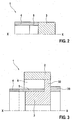
- FIG. 2 shows a second known example of a one-piece component 1, in which the one-piece component is provided without a housing.
- the one-piece component comprises only a cylindrical magnet sleeve 4 made of a magnetically conductive material, a cylindrical, non-magnetic separating sleeve 5 and a cylindrical inner pole 3.
- the separating sleeve 5 is arranged at a front end of the inner pole 3, so that the one-piece component 1 has a constant outer diameter.
- FIG. 3 shows a third known example in which the inner pole 3 has an outwardly directed, radial flange 30 which projects radially outward from a cylindrical main body of the inner pole 3. If appropriate, this radial flange 30 can also be subdivided into segments by providing electrically non-conductive subregions between the individual segments.
- This embodiment of the one-piece component 1 results in a further improvement, ie reduction, of occurring eddy currents.
- the valve housing comprises in this embodiment two cylindrical sections 2 and 20.
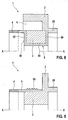
- FIGS. 4 and 5 show a fourth known example in which the non-magnetic separating sleeve 5 has a cylindrical base portion and at a first axial end a radially outwardly directed first wall portion 51. Furthermore, the separating sleeve 5 has at a second axial end a radially outwardly directed second wall region 52. Thus results in the axial direction XX between the two wall portions 51, 52 a Receiving space 6 for receiving a winding 7 (see. FIGS. 4 and 5 ). After the winding 7 has been wound on the outer periphery of the separating sleeve 5 between the wall portions 51, 52, a cover sleeve 8 is pushed over, which covers the winding 7. A part of the valve housing 2 is integrally formed with the inner pole 3, another part of the valve housing is provided by the separate cover sleeve 8. The cylindrical inner pole is arranged radially inside the separating sleeve 5.
- FIGS. 6 and 7 Fifth known example shown corresponds substantially to the fourth embodiment, wherein additionally in the cylindrical inner pole 3, a plurality of segmentation regions 53, 54 are provided, which are made of electrically non-conductive material.
- the segmentation areas 53, 54 are provided as extending in the axial direction XX wall portions which are integrally formed on the inner periphery of the separating sleeve 5 extending radially inwardly.
- the inner pole 3 is divided into a plurality of segments 3a, 3b, 3c, whereby the generation of eddy currents can be minimized during operation. As a result, a more powerful magnetic circuit is obtained.
- FIG. 8 shows an embodiment of a one-piece component 1 according to the invention, in which the separating sleeve 5 made of a non-magnetic material has a radially outwardly directed first wall portion 57 and a second wall portion 58.
- the inner pole 3 is accommodated in the sixth exemplary embodiment and arranged radially outside the base region 50. How out FIG. 8 it can be seen, the inner pole 3 is thus enclosed by the separating sleeve 5 from three sides. Between a radial outer side of the inner pole 3 and the valve housing 2, in turn, the receiving space 6 is provided for receiving the winding, not shown.
- the separating sleeve 5 in addition to the function of magnetic separation additionally provides protection against aggressive media, such as fuel for the inner pole 3 ready.
- the magnetic material for the inner pole 3 can be designed with a maximum saturation induction.
- a stop surface 56 may additionally be provided for a valve needle and a component connected to the valve needle.
- a separate component for a stop be dispensed with for the valve needle.
- FIG. 9 shows a sixth known example, which has a separating sleeve 5 made of non-magnetic material, on the outer periphery of a profiling 55 is formed.
- the profiling 55 includes a plurality of annular grooves and ridges to receive a coil (not shown).
- a winding support is integrated, so that the number of parts for the injection valve can be further reduced by integration of the winding support. It should be noted that such an integrated winding support may also be provided in the other known examples described, with the exception of the embodiment.
Landscapes
- Engineering & Computer Science (AREA)
- Physics & Mathematics (AREA)
- Electromagnetism (AREA)
- General Engineering & Computer Science (AREA)
- Mechanical Engineering (AREA)
- Chemical & Material Sciences (AREA)
- Combustion & Propulsion (AREA)
- Magnetically Actuated Valves (AREA)
- Fuel-Injection Apparatus (AREA)
- Electromagnets (AREA)
Description
- Die vorliegende Erfindung betrifft ein einstückiges Bauteil, insbesondere ein Ventilbauteil, und einen Magnetaktor, insbesondere ein Magnetventil mit einer reduzierten Bauteilezahl, sowie ein Verfahren zur einfachen und kostengünstigen Herstellung eines Bauteils.
- Magnetventile sind aus dem Stand der Technik in unterschiedlichen Ausgestaltungen bekannt. Bei modernen Einspritzanlagen werden häufig elektromagnetische Ventile eingesetzt, welche einen möglichst leistungsfähigen Magnetkreis aufweisen sollten, um insbesondere kurze Schaltzeiten sowie ein reproduzierbares Öffnungs- und Schließverhalten zu ermöglichen.
- Aus der
DE 10 2009 046 466 A1 ist ein Einspritzventil bekannt, welches einen Ventilsitzträger aufweist, der als einteiliges Bauteil hergestellt ist und welcher einen ersten und einen zweiten Bereich aus magnetischem bzw. nichtmagnetischem Material aufweist. Dieser Ventilsitzträger kann beispielsweise mittels eines MIM-Verfahrens (Metall-Injection-Molding) hergestellt werden. Hierbei werden jedoch für beide Bereiche jeweils metallische Werkstoffe verwendet. Es wäre jedoch wünschenswert, ein Einspritzventil bzw. ein Verfahren zu dessen Herstellung bereitzustellen, welches eine weitere Reduktion der Herstellkosten ermöglicht. - Aus der
DE 10 2005 052 252 A1 ist bereits ein einteiliges Bauteil für einen Magnetaktor, insbesondere ein Magnetventil in Form eines Brennstoffeinspritzventils bekannt. Das Bauteil umfasst dabei einen Innenpol, eine Magnethülse und eine unmagnetische Trennhülse, wobei der Innenpol, die Magnethülse und die Trennhülse in das einteilige Bauteil integriert sind. - Offenbarung der Erfindung Das erfindungsgemäße einteilige Bauteil mit den Merkmalen des Anspruchs 1 weist demgegenüber den Vorteil auf, dass ein Magnetaktor mit einem leistungsfähigen Magnetkreis bereitgestellt werden kann, bei welchem die Herstellkosten weiter signifikant reduziert werden können. Ferner ist eine Bauteileanzahl durch das erfindungsgemäße Bauteil weiter reduziert. Erfindungsgemäß kann durch den leistungsfähigen Magnetkreis erreicht werden, dass kurze Schaltzeiten und reproduzierbare Öffnungsverhalten und Schließverhalten eines Magnetaktors realisiert werden können. Dies wird erfindungsgemäß dadurch erreicht, dass das einteilige Bauteil zumindest einen elektromagnetischen Aktor mit einem Innenpol, eine Magnethülse und eine unmagnetische Trennhülse aufweist. Dabei sind der Innenpol, die Magnethülse und die Trennhülse zu einem einteiligen Bauteil integriert. Somit liegt zwischen den Teilen Innenpol, Magnethülse und Trennhülse eine stoffschlüssige Verbindung vor. Hierdurch können weiter auch insbesondere die Montagezeiten für den Magnetaktor reduziert werden. Die unmagnetische Trennhülse stellt dabei neben einer Fluiddichtheit nach außen auch eine Minimierung von Wirbelströmen sicher. Insbesondere kann eine an einer Außenseite der Trennhülse angeordnete Wicklung frei von Kraftstoff, welcher üblicherweise die Bauteile sehr stark angreift, gehalten werden.
- Die Unteransprüche zeigen bevorzugte Weiterbildungen der Erfindung. Weiter bevorzugt umfasst das einteilige Bauteil ein Gehäuse, welches zusätzlich in das einteilige Bauteil integriert ist. Hierdurch kann die Bauteilezahl weiter reduziert werden und eine noch kostengünstigere Herstellung erreicht werden.
- Gemäß einer bevorzugten Ausgestaltung der Erfindung weist das Gehäuse einen in axialer Richtung vorstehenden Anbindungsflansch für eine Anbindung des einteiligen Bauteils auf. Hierdurch kann das einteilige Bauteil einfach und sicher an andere Bauteile, z.B. an Bauteile eines Einspritzventils, angebunden werden.
- Erfindungsgemäß weist die Trennhülse an einem ersten Ende einen radial gerichteten ersten Wandbereich auf und an einem zweiten Ende einen radial gerichteten zweiten Wandbereich auf. Hierdurch wird zwischen den beiden Wandbereichen ein Aufnahmeraum für die Wicklung geschaffen, so dass die Wicklung schnell und einfach auf die Trennhülse zwischen den Wandbereichen gewickelt werden kann. Gegebenenfalls kann bevorzugt zur Abdeckung noch eine vorzugsweise geschlitzte Hülse über die Wicklung geschoben werden.
- Gemäß einer alternativen Ausgestaltung der vorliegenden Erfindung ist zwischen den beiden Wandbereichen an der Trennhülse der Innenpol des einteiligen Bauteils angeordnet. Hierdurch kann eine besonders geschützte Anordnung des Innenpols erreicht werden. Insbesondere ist der Magnetwerkstoff des Innenpols vor aggressiven Medien, wie z.B. Kraftstoff, geschützt. Als Magnetwerkstoff kann dadurch beispielsweise Reineisen verwendet werden. Darüber hinaus kann eine äußere, in axialer Richtung gerichtete Fläche der Trennhülse als Anschlagfläche, beispielsweise für einen Anschlag eines Ankers eines Magnetventils, genutzt werden.
- Das erfindungsgemäße Bauteil wird insbesondere als Einspritzventil bei der Einspritzung von Kraftstoffen bei Fahrzeugen verwendet.
- Zeichnung Nachfolgend werden bevorzugte Ausführungsbeispiele der Erfindung unter Bezugnahme auf die begleitende Zeichnung im Detail beschrieben. In der Zeichnung ist:
- Figur 1
- eine schematische Schnittansicht eines einteiligen Bauteils für ein Einspritzventil gemäß einem ersten bekannten Beispiel.
- Figur 2
- eine schematische Schnittansicht eines einteiligen Bauteils für einen Magnetaktor gemäß einem zweiten bekannten Beispiel,
- Figur 3
- eine schematische Schnittansicht eines einteiligen Bauteils für ein Einspritzventil gemäß einem dritten bekannten Beispiel,
- Figur 4
- eine schematische Schnittansicht eines einteiligen Bauteils für ein Einspritzventil gemäß einem vierten bekannten Beispiel,
- Figur 5
- eine schematische Schnittansicht des einteiligen Bauteils von
Figur 4 mit montierter Wicklung, - Figur 6
- eine schematische Schnittansicht eines einteiligen Bauteils für ein Einspritzventil gemäß einem fünften bekannten Beispiel,
- Figur 7
- eine schematische Schnittansicht des einteiligen Bauteils von
Figur 6 entlang der Linie V-V, - Figur 8
- eine schematische Schnittansicht eines einteiligen Bauteils für ein Einspritzventil gemäß einem Ausführungsbeispiel der Erfindung, und
- Figur 9
- eine schematische Schnittansicht eines einteiligen Bauteils für ein Einspritzventil gemäß einem sechsten bekannten Beispiel.
- Bevorzugte Ausführungsformen der Erfindung Nachfolgend wird unter Bezugnahme auf
Figur 1 ein als einteiliges Ventilbauteil 1 vorgesehenes einteiliges Bauteil gemäß einem ersten bekannten Beispiel im Detail beschrieben. - Wie aus
Figur 1 ersichtlich ist, umfasst das einteilige Ventilbauteil 1 ein Ventilgehäuse 2, welches aus einem metallischen Material hergestellt ist sowie einen zylindrischen Innenpol 3, welcher aus einem magnetisierbaren Material hergestellt ist. Weiterhin umfasst das einteilige Ventilbauteil 1 eine zylindrische Magnethülse 4 aus einem magnetisch leitfähigen Material sowie eine zylindrische Trennhülse 5 aus einem unmagnetischen Material, beispielsweise einem austenitischen Material oder einer Keramik. Mit X-X ist eine Axialachse des einteiligen Ventilbauteils 1 bezeichnet, in deren Richtung ein Nadelhub einer nicht gezeigten Nadel ausgeführt wird. - Weiterhin ist zwischen der Trennhülse 5 und dem Ventilgehäuse 2 ein Aufnahmeraum 6 zur Aufnahme einer Wicklung (nicht gezeigt) vorgesehen. Das Bezugszeichen 20 bezeichnet einen Anbindungsflansch.
- Somit ist bei dem einteiligen Ventilbauteil 1 eine unmagnetische Trennhülse 5 integriert, wobei zwischen den beschriebenen Teilbereichen, umfassend das Ventilgehäuse 2, den Innenpol 3, die Magnethülse 4 und die Trennhülse 5 jeweils eine stoffschlüssige Verbindung vorhanden ist. Das einteilige Ventilbauteil wird durch ein Zwei-Komponenten-Pulver-Spritzgussverfahren hergestellt. Durch die Integration der unmagnetischen Trennhülse 5 können magnetische Verluste in der Trennhülse vermieden werden. Die magnetischen Feldlinien verlaufen zwischen Anker und Innenpol und nicht über die Trennhülse. Dadurch kann ein leistungsfähiger und sehr kostengünstig herstellbarer Magnetkreis für ein Magnetventil bereitgestellt werden. Durch die Integration der unmagnetischen Trennhülse 5 in das einteilige Ventilbauteil 1 wird auch eine Funktion einer magnetischen Trennung in das einteilige Ventilbauteil 1 integriert. Ein Magnetwerkstoff des Innenpols 3 ist vorzugsweise mit möglichst hoher Sättigungsinduktion ausgeführt, um die Magneteffizienz zu optimieren. Darüber hinaus stellt das einteilige Ventilbauteil ferner eine kraftstoffdichte und hochdruckdichte Verbindung zwischen den einzelnen Teilen bereit, ohne dass hier aufwendige Verbindungstechniken, wie beispielsweise Schweißen oder dgl., notwendig sind. Die dichte Verbindung wird dabei durch das Zwei-Komponenten-Pulver-Spritzgussverfahren erreicht.
- Die
Figuren 2 bis 7 zeigen alternative bekannte Beispiele, wobei jeweils gleiche bzw. funktional gleiche Teile mit den gleichen Bezugszeichen wie im ersten bekannten Beispiel bezeichnet sind. -
Figur 2 zeigt ein zweites bekanntes Beispiel eines einteiligen Bauteils 1, bei dem das einteilige Bauteil ohne Gehäuse vorgesehen ist. Somit umfasst das einteilige Bauteil lediglich eine zylindrische Magnethülse 4 aus einem magnetisch leitfähigen Material, eine zylindrische, unmagnetische Trennhülse 5 und einen zylindrischen Innenpol 3. Wie ausFigur 2 ersichtlich ist, ist die Trennhülse 5 dabei an einem stirnseitigen Ende des Innenpols 3 angeordnet, so dass das einteilige Bauteil 1 einen konstanten Außendurchmesser aufweist. -
Figur 3 zeigt ein drittes bekanntes Beispiel, bei dem der Innenpol 3 einen nach außen gerichteten, radialen Flansch 30 aufweist, welcher von einem zylindrischen Hauptkörper des Innenpols 3 radial nach außen vorsteht. Dieser radiale Flansch 30 kann gegebenenfalls auch in Segmente unterteilt werden, indem zwischen den einzelnen Segmenten elektrisch nicht leitende Teilbereiche vorgesehen werden. Diese Ausgestaltung des einteiligen Bauteils 1 ergibt eine weitere Verbesserung, d.h., Reduzierung, von auftretenden Wirbelströmen. Das Ventilgehäuse umfasst in diesem Ausführungsbeispiel zwei zylindrische Teilbereiche 2 und 20. - Die
Figuren 4 und 5 zeigen ein viertes bekanntes Beispiel, bei dem die unmagnetische Trennhülse 5 einen zylindrischen Basisbereich und an einem ersten axialen Ende einen radial nach außen gerichteten ersten Wandbereich 51 aufweist. Ferner weist die Trennhülse 5 an einem zweiten axialen Ende einen radial nach außen gerichteten zweiten Wandbereich 52 auf. Somit ergibt sich in axialer Richtung X-X zwischen den beiden Wandbereichen 51, 52 ein Aufnahmeraum 6 zur Aufnahme einer Wicklung 7 (vgl.Figuren 4 und 5 ). Nachdem die Wicklung 7 auf dem äußeren Umfang der Trennhülse 5 zwischen die Wandbereiche 51, 52 aufgewickelt wurde, wird eine Abdeckhülse 8 übergeschoben, welche die Wicklung 7 abdeckt. Ein Teil des Ventilgehäuses 2 ist einstückig mit dem Innenpol 3 gebildet, ein anderer Teil des Ventilgehäuses wird durch die separate Abdeckhülse 8 bereitgestellt. Der zylindrische Innenpol ist radial innerhalb der Trennhülse 5 angeordnet. - Das in den
Figuren 6 und 7 gezeigte fünfte bekanntes Beispiel entspricht im Wesentlichen dem vierten Ausführungsbeispiel, wobei zusätzlich noch im zylindrischen Innenpol 3 eine Vielzahl von Segmentierungsbereichen 53, 54 vorgesehen sind, die aus elektrisch nicht leitendem Material hergestellt sind. Die Segmentierungsbereiche 53, 54 sind als in Axialrichtung X-X verlaufende Wandbereiche vorgesehen, welche einteilig am inneren Umfang der Trennhülse 5 radial nach Innen verlaufend ausgebildet sind. Hierdurch wird der Innenpol 3 in mehrere Segmente 3a, 3b, 3c unterteilt, wodurch im Betrieb die Entstehung von Wirbelströmen minimiert werden kann. Hierdurch wird ein leistungsstärkerer Magnetkreis erhalten. -
Figur 8 zeigt ein Ausführungsbeispiel einen erfindungsgemäßen einteiligen Bauteils 1, bei dem die aus einem unmagnetischen Material hergestellte Trennhülse 5 einen radial nach außen gerichteten ersten Wandbereich 57 und einen zweiten Wandbereich 58 aufweist. In dem in axialer Richtung zwischen den beiden Wandbereichen 57, 58 gebildeten Raum ist beim sechsten Ausführungsbeispiel jedoch der Innenpol 3 aufgenommen und radial außerhalb des Basisbereichs 50 angeordnet. Wie ausFigur 8 ersichtlich ist, ist der Innenpol 3 somit von drei Seiten von der Trennhülse 5 umschlossen. Zwischen einer radialen äußeren Seite des Innenpols 3 und dem Ventilgehäuse 2 ist wiederum der Aufnahmeraum 6 zur Aufnahme der nicht gezeigten Wicklung vorgesehen. Somit stellt die Trennhülse 5 neben der Funktion der magnetischen Trennung zusätzlich noch einen Schutz gegen aggressive Medien, wie beispielsweise Kraftstoff für den Innenpol 3, bereit. Hierdurch kann der Magnetwerkstoff für den Innenpol 3 mit einer maximalen Sättigungsinduktion ausgeführt werden. Abhängig von der Materialwahl für die Trennhülse 5 kann zusätzlich noch eine Anschlagfläche 56 für eine Ventilnadel und ein mit der Ventilnadel verbundenes Bauteil vorgesehen werden. Hierdurch kann insbesondere ein separates Bauteil für einen Anschlag für die Ventilnadel verzichtet werden. Mit dieser Ausführungsform des einteiligen Bauteils 1 kann insbesondere ein sehr kompakter Aufbau für das Einspritzventil realisiert werden. -
Figur 9 zeigt ein sechstes bekanntes Beispiel, welches eine Trennhülse 5 aus unmagnetischem Material aufweist, an dessen äußerem Umfang eine Profilierung 55 ausgebildet ist. Die Profilierung 55 umfasst eine Vielzahl von ringförmig verlaufenden Nuten und Erhebungen, um eine Wicklung (nicht gezeigt) aufzunehmen. Somit ist in die unmagnetische Trennhülse 5 ferner noch ein Wicklungsträger integriert, so dass die Teileanzahl für das Einspritzventil durch Integration des Wicklungsträgers weiter reduziert werden kann. Es sei angemerkt, dass ein derartiger integrierter Wicklungsträger auch bei den anderen beschriebenen bekannten Beispielen, mit Ausnahme des Ausführungsbeispiels, vorgesehen sein kann. - Zu dem beschriebenen Ausführungsbeispiel sei angemerkt, dass dieses sowohl mit einem einstückigen Innenpol 3 oder auch mit einem in mehrere Segmente unterteilten Innenpol ausgeführt werden können.
- Ferner sei angemerkt, dass das beschriebene Ausführungsbeispiel statt bei Magnetventilen auch auf anderen technischen Gebieten als Magnetaktoren verwendet werden kann.
Claims (5)
- Einteiliges Bauteil für einen Magnetaktor, insbesondere ein Magnetventil, umfassend:- einen Innenpol (3),- eine Magnethülse (4), und- eine unmagnetische Trennhülse (5),- wobei der Innenpol (3), die Magnethülse (4) und die Trennhülse (5) in das einteilige Bauteil integriert sind,dadurch gekennzeichnet,
dass die Trennhülse (5) einen radial gerichteten ersten Wandbereich (57) aufweist und einen radial gerichteten zweiten Wandbereich (58) aufweist und dass der Innenpol (3) zwischen dem ersten Wandbereich (57) und dem zweiten Wandbereich (58) angeordnet ist. - Bauteil nach Anspruch 1, ferner umfassend ein Gehäuse (2), welches zusätzlich in das einteilige Bauteil integriert ist.
- Bauteil nach Anspruch 2, dadurch gekennzeichnet, dass das Gehäuse (2) einen Anbindungsflansch (20) für eine Anbindung des einteiligen Bauteils aufweist.
- Bauteil nach Anspruch 1, dadurch gekennzeichnet, dass einer der Wandbereiche (57, 58) der Trennhülse (5) einen Anschlag (56) für eine Ventilnadel oder ein mit der Ventilnadel verbundenes Bauteil bildet.
- Magnetventil mit einem Magnetaktor, insbesondere Einspritzventil, zur Einspritzung von Kraftstoff, umfassend ein Bauteil nach einem der vorhergehenden Ansprüche.
Applications Claiming Priority (3)
| Application Number | Priority Date | Filing Date | Title |
|---|---|---|---|
| DE102011078255 | 2011-06-29 | ||
| DE201110088463 DE102011088463A1 (de) | 2011-06-29 | 2011-12-14 | Bauteil für einen Magnetaktor sowie Verfahren zu dessen Herstellung |
| PCT/EP2012/058437 WO2013000611A1 (de) | 2011-06-29 | 2012-05-08 | Bauteil für einen magnetaktor sowie verfahren zu dessen herstellung |
Publications (2)
| Publication Number | Publication Date |
|---|---|
| EP2726729A1 EP2726729A1 (de) | 2014-05-07 |
| EP2726729B1 true EP2726729B1 (de) | 2016-08-10 |
Family
ID=47355078
Family Applications (1)
| Application Number | Title | Priority Date | Filing Date |
|---|---|---|---|
| EP12722695.9A Not-in-force EP2726729B1 (de) | 2011-06-29 | 2012-05-08 | Bauteil für einen magnetaktor |
Country Status (7)
| Country | Link |
|---|---|
| US (1) | US9651163B2 (de) |
| EP (1) | EP2726729B1 (de) |
| JP (2) | JP5788090B2 (de) |
| KR (1) | KR101947368B1 (de) |
| CN (1) | CN103620207B (de) |
| DE (1) | DE102011088463A1 (de) |
| WO (1) | WO2013000611A1 (de) |
Families Citing this family (1)
| Publication number | Priority date | Publication date | Assignee | Title |
|---|---|---|---|---|
| DE102020106013B4 (de) * | 2020-03-05 | 2022-09-29 | Kendrion (Villingen) Gmbh | Herstellungsverfahren eines Polkerns, Polkern, elektromagnetischer Aktor, Schwingungsdämpfer sowie Fahrzeug |
Family Cites Families (31)
| Publication number | Priority date | Publication date | Assignee | Title |
|---|---|---|---|---|
| US3696837A (en) * | 1971-05-07 | 1972-10-10 | Gpe Controls Inc | Electromagnetic fluid control valve |
| DE3336010A1 (de) * | 1983-10-04 | 1985-04-18 | Robert Bosch Gmbh, 7000 Stuttgart | Elektromagnetisch betaetigbares ventil |
| JP2989977B2 (ja) | 1991-12-17 | 1999-12-13 | 三菱電機株式会社 | 燃料噴射装置の固定鉄心の製造方法 |
| JP2573574Y2 (ja) * | 1992-04-21 | 1998-06-04 | 本田技研工業株式会社 | 電磁式燃料噴射弁 |
| US5207410A (en) * | 1992-06-03 | 1993-05-04 | Siemens Automotive L.P. | Means for improving the opening response of a solenoid operated fuel valve |
| US5515818A (en) * | 1993-12-15 | 1996-05-14 | Machine Research Corporation Of Chicago | Electromechanical variable valve actuator |
| DE4432525A1 (de) * | 1994-09-13 | 1996-03-14 | Bosch Gmbh Robert | Verfahren zur Herstellung eines Magnetkreises für ein Ventil |
| DE19629589B4 (de) * | 1996-07-23 | 2007-08-30 | Robert Bosch Gmbh | Brennstoffeinspritzventil |
| US5900793A (en) * | 1997-07-23 | 1999-05-04 | Odin Technologies Ltd | Permanent magnet assemblies for use in medical applications |
| DE19727414A1 (de) * | 1997-06-27 | 1999-01-07 | Bosch Gmbh Robert | Verfahren zur Herstellung einer Magnetspule für ein Ventil und Ventil mit einer Magnetspule |
| DE19808067A1 (de) * | 1998-02-26 | 1999-09-02 | Bosch Gmbh Robert | Elektromagnetisch betätigbares Ventil |
| DE19924814A1 (de) * | 1999-05-29 | 2000-12-07 | Daimler Chrysler Ag | Aktor zur elektromagnetischen Ventilsteuerung |
| JP2001148308A (ja) | 1999-11-19 | 2001-05-29 | Toyota Motor Corp | ソレノイド |
| DE10039039A1 (de) | 2000-08-10 | 2002-02-21 | Bosch Gmbh Robert | Magnetventil zur Steuerung eines Einspritzventils für Brennkraftmaschinen und Elektromagnet dafür |
| JP4329250B2 (ja) | 2000-09-20 | 2009-09-09 | 株式会社デンソー | 電磁式アクチュエータの製造方法 |
| JP2004323869A (ja) * | 2003-04-21 | 2004-11-18 | Aisin Seiki Co Ltd | 酸化物膜付鉄鋼部材の製造方法 |
| JP2005005652A (ja) | 2003-06-16 | 2005-01-06 | Denso Corp | コイル装置 |
| JP4182847B2 (ja) | 2003-09-11 | 2008-11-19 | トヨタ自動車株式会社 | 可変圧縮比内燃機関の制御装置 |
| JP2005089777A (ja) * | 2003-09-12 | 2005-04-07 | Aisin Seiki Co Ltd | 複合焼結部材の製造方法 |
| JP2005101345A (ja) | 2003-09-25 | 2005-04-14 | Aisin Seiki Co Ltd | リニアソレノイドバルブ |
| JP3819907B2 (ja) * | 2004-02-27 | 2006-09-13 | 株式会社ケーヒン | 電磁式燃料噴射弁およびその製造方法 |
| JP2005311248A (ja) | 2004-04-26 | 2005-11-04 | Toyoda Mach Works Ltd | 磁路構成焼結部材及びその製造方法 |
| DE102005052252A1 (de) * | 2005-11-02 | 2007-05-03 | Robert Bosch Gmbh | Brennstoffeinspritzventil |
| JP4432919B2 (ja) | 2006-03-07 | 2010-03-17 | 株式会社デンソー | 燃料噴射弁 |
| JP5070836B2 (ja) | 2006-12-26 | 2012-11-14 | アイシン・エィ・ダブリュ株式会社 | ソレノイド駆動装置及びソレノイドバルブ |
| US7552719B2 (en) * | 2007-12-04 | 2009-06-30 | Caterpillar Inc. | Solenoid assembly having slotted stator |
| DE102008040545A1 (de) | 2008-07-18 | 2010-01-21 | Robert Bosch Gmbh | Metallisches Verbundbauteil, insbesondere für ein elektromagnetisches Ventil |
| DE102008035332A1 (de) * | 2008-07-29 | 2010-02-04 | Robert Bosch Gmbh | Hubmagnetanordnung und Ventilanordnung |
| DE102009046466A1 (de) | 2009-11-06 | 2011-05-12 | Robert Bosch Gmbh | MIM 2K-Hülse für Einspritzventil |
| DE102009055133A1 (de) * | 2009-12-22 | 2011-06-30 | Robert Bosch GmbH, 70469 | Polkern für Magnetventile hergestellt mittels Mehrstoff-MIM |
| DE102010038437B4 (de) * | 2010-07-27 | 2022-08-25 | Robert Bosch Gmbh | Magnetaktor und Verfahren zur Herstellung eines einstückigen Polkerns für einen Magnetaktor |
-
2011
- 2011-12-14 DE DE201110088463 patent/DE102011088463A1/de not_active Withdrawn
-
2012
- 2012-05-08 WO PCT/EP2012/058437 patent/WO2013000611A1/de not_active Ceased
- 2012-05-08 EP EP12722695.9A patent/EP2726729B1/de not_active Not-in-force
- 2012-05-08 CN CN201280031585.2A patent/CN103620207B/zh not_active Expired - Fee Related
- 2012-05-08 US US14/129,182 patent/US9651163B2/en not_active Expired - Fee Related
- 2012-05-08 KR KR1020137034672A patent/KR101947368B1/ko not_active Expired - Fee Related
- 2012-05-08 JP JP2014516239A patent/JP5788090B2/ja not_active Expired - Fee Related
-
2015
- 2015-07-27 JP JP2015147515A patent/JP6111294B2/ja not_active Expired - Fee Related
Also Published As
| Publication number | Publication date |
|---|---|
| US20140197340A1 (en) | 2014-07-17 |
| EP2726729A1 (de) | 2014-05-07 |
| CN103620207B (zh) | 2016-10-12 |
| KR20140037146A (ko) | 2014-03-26 |
| US9651163B2 (en) | 2017-05-16 |
| KR101947368B1 (ko) | 2019-02-13 |
| CN103620207A (zh) | 2014-03-05 |
| JP2015232397A (ja) | 2015-12-24 |
| DE102011088463A1 (de) | 2013-01-03 |
| JP2014526017A (ja) | 2014-10-02 |
| WO2013000611A1 (de) | 2013-01-03 |
| JP5788090B2 (ja) | 2015-09-30 |
| JP6111294B2 (ja) | 2017-04-05 |
Similar Documents
| Publication | Publication Date | Title |
|---|---|---|
| EP2291852B1 (de) | Betätigungsvorrichtung | |
| EP2557576A2 (de) | Magnetanker | |
| DE102010056435A1 (de) | Solenoidbetätigte Vorrichtung und Verfahren dafür | |
| EP2313896B1 (de) | Metallisches verbundbauteil, insbesondere für ein elektromagnetisches ventil | |
| DE102010045601A1 (de) | Elektromagnetische Stellvorrichtung | |
| EP2793243B1 (de) | Elektromagnetischer Aktuator | |
| DE102016224288A1 (de) | Elektromagnetisches Stellglied, Flussscheibenkörper für ein elektromagnetisches Stellglied und Verfahren zur Herstellung eines elektromagnetischen Stellgliedes | |
| DE102010038437A1 (de) | Magnetaktor | |
| DE102009055133A1 (de) | Polkern für Magnetventile hergestellt mittels Mehrstoff-MIM | |
| DE102011001281A1 (de) | Magnetspulenventil | |
| DE102013206959A1 (de) | Magnetventil mit verbessertem Öffnungs- und Schließverhalten | |
| EP3454349B1 (de) | Verfahren zur herstellung eines magnetanker-stössel-verbundes und magnetanker-stössel-verbund für einen linearaktuator | |
| DE102004023905B4 (de) | Elektromagnetische Betätigungseinrichtung | |
| EP2726729A1 (de) | Bauteil für einen magnetaktor sowie verfahren zu dessen herstellung | |
| DE102015006517A1 (de) | Ventilmagnetschalter | |
| EP4194720A1 (de) | Verriegelungseinheit | |
| EP2986839B1 (de) | Magnetventil mit verbessertem öffnungs- und schliessverhalten | |
| EP3455487B1 (de) | Injektor mit verbessertem magnetaktor | |
| DE102007004254A1 (de) | Elektromagnetische Stellvorrichtung | |
| EP2338750B1 (de) | Magnetventil sowie Fahrerassistenzeinrichtung | |
| DE112016006658T5 (de) | Elektromagnetischer Aktor und Verfahren zur Herstellung desselben | |
| DE102015206201A1 (de) | Gasventil | |
| DE102013201756A1 (de) | Steuerventil mit zwei Magnetspulen | |
| EP2291851A1 (de) | Betätigungsvorrichtung | |
| DE102013224863A1 (de) | Magnetaktor für einen Kraftstoffinjektor sowie Kraftstoffinjektor |
Legal Events
| Date | Code | Title | Description |
|---|---|---|---|
| PUAI | Public reference made under article 153(3) epc to a published international application that has entered the european phase |
Free format text: ORIGINAL CODE: 0009012 |
|
| 17P | Request for examination filed |
Effective date: 20140129 |
|
| AK | Designated contracting states |
Kind code of ref document: A1 Designated state(s): AL AT BE BG CH CY CZ DE DK EE ES FI FR GB GR HR HU IE IS IT LI LT LU LV MC MK MT NL NO PL PT RO RS SE SI SK SM TR |
|
| DAX | Request for extension of the european patent (deleted) | ||
| GRAP | Despatch of communication of intention to grant a patent |
Free format text: ORIGINAL CODE: EPIDOSNIGR1 |
|
| INTG | Intention to grant announced |
Effective date: 20160506 |
|
| GRAS | Grant fee paid |
Free format text: ORIGINAL CODE: EPIDOSNIGR3 |
|
| GRAA | (expected) grant |
Free format text: ORIGINAL CODE: 0009210 |
|
| AK | Designated contracting states |
Kind code of ref document: B1 Designated state(s): AL AT BE BG CH CY CZ DE DK EE ES FI FR GB GR HR HU IE IS IT LI LT LU LV MC MK MT NL NO PL PT RO RS SE SI SK SM TR |
|
| REG | Reference to a national code |
Ref country code: GB Ref legal event code: FG4D Free format text: NOT ENGLISH |
|
| REG | Reference to a national code |
Ref country code: CH Ref legal event code: EP Ref country code: AT Ref legal event code: REF Ref document number: 819297 Country of ref document: AT Kind code of ref document: T Effective date: 20160815 |
|
| REG | Reference to a national code |
Ref country code: IE Ref legal event code: FG4D Free format text: LANGUAGE OF EP DOCUMENT: GERMAN |
|
| REG | Reference to a national code |
Ref country code: DE Ref legal event code: R096 Ref document number: 502012007894 Country of ref document: DE |
|
| REG | Reference to a national code |
Ref country code: LT Ref legal event code: MG4D |
|
| REG | Reference to a national code |
Ref country code: NL Ref legal event code: MP Effective date: 20160810 |
|
| PG25 | Lapsed in a contracting state [announced via postgrant information from national office to epo] |
Ref country code: RS Free format text: LAPSE BECAUSE OF FAILURE TO SUBMIT A TRANSLATION OF THE DESCRIPTION OR TO PAY THE FEE WITHIN THE PRESCRIBED TIME-LIMIT Effective date: 20160810 Ref country code: HR Free format text: LAPSE BECAUSE OF FAILURE TO SUBMIT A TRANSLATION OF THE DESCRIPTION OR TO PAY THE FEE WITHIN THE PRESCRIBED TIME-LIMIT Effective date: 20160810 Ref country code: IS Free format text: LAPSE BECAUSE OF FAILURE TO SUBMIT A TRANSLATION OF THE DESCRIPTION OR TO PAY THE FEE WITHIN THE PRESCRIBED TIME-LIMIT Effective date: 20161210 Ref country code: FI Free format text: LAPSE BECAUSE OF FAILURE TO SUBMIT A TRANSLATION OF THE DESCRIPTION OR TO PAY THE FEE WITHIN THE PRESCRIBED TIME-LIMIT Effective date: 20160810 Ref country code: NL Free format text: LAPSE BECAUSE OF FAILURE TO SUBMIT A TRANSLATION OF THE DESCRIPTION OR TO PAY THE FEE WITHIN THE PRESCRIBED TIME-LIMIT Effective date: 20160810 Ref country code: LT Free format text: LAPSE BECAUSE OF FAILURE TO SUBMIT A TRANSLATION OF THE DESCRIPTION OR TO PAY THE FEE WITHIN THE PRESCRIBED TIME-LIMIT Effective date: 20160810 Ref country code: NO Free format text: LAPSE BECAUSE OF FAILURE TO SUBMIT A TRANSLATION OF THE DESCRIPTION OR TO PAY THE FEE WITHIN THE PRESCRIBED TIME-LIMIT Effective date: 20161110 |
|
| PG25 | Lapsed in a contracting state [announced via postgrant information from national office to epo] |
Ref country code: GR Free format text: LAPSE BECAUSE OF FAILURE TO SUBMIT A TRANSLATION OF THE DESCRIPTION OR TO PAY THE FEE WITHIN THE PRESCRIBED TIME-LIMIT Effective date: 20161111 Ref country code: PT Free format text: LAPSE BECAUSE OF FAILURE TO SUBMIT A TRANSLATION OF THE DESCRIPTION OR TO PAY THE FEE WITHIN THE PRESCRIBED TIME-LIMIT Effective date: 20161212 Ref country code: LV Free format text: LAPSE BECAUSE OF FAILURE TO SUBMIT A TRANSLATION OF THE DESCRIPTION OR TO PAY THE FEE WITHIN THE PRESCRIBED TIME-LIMIT Effective date: 20160810 Ref country code: PL Free format text: LAPSE BECAUSE OF FAILURE TO SUBMIT A TRANSLATION OF THE DESCRIPTION OR TO PAY THE FEE WITHIN THE PRESCRIBED TIME-LIMIT Effective date: 20160810 Ref country code: SE Free format text: LAPSE BECAUSE OF FAILURE TO SUBMIT A TRANSLATION OF THE DESCRIPTION OR TO PAY THE FEE WITHIN THE PRESCRIBED TIME-LIMIT Effective date: 20160810 Ref country code: ES Free format text: LAPSE BECAUSE OF FAILURE TO SUBMIT A TRANSLATION OF THE DESCRIPTION OR TO PAY THE FEE WITHIN THE PRESCRIBED TIME-LIMIT Effective date: 20160810 |
|
| PG25 | Lapsed in a contracting state [announced via postgrant information from national office to epo] |
Ref country code: RO Free format text: LAPSE BECAUSE OF FAILURE TO SUBMIT A TRANSLATION OF THE DESCRIPTION OR TO PAY THE FEE WITHIN THE PRESCRIBED TIME-LIMIT Effective date: 20160810 Ref country code: EE Free format text: LAPSE BECAUSE OF FAILURE TO SUBMIT A TRANSLATION OF THE DESCRIPTION OR TO PAY THE FEE WITHIN THE PRESCRIBED TIME-LIMIT Effective date: 20160810 |
|
| REG | Reference to a national code |
Ref country code: DE Ref legal event code: R097 Ref document number: 502012007894 Country of ref document: DE |
|
| REG | Reference to a national code |
Ref country code: FR Ref legal event code: PLFP Year of fee payment: 6 |
|
| PG25 | Lapsed in a contracting state [announced via postgrant information from national office to epo] |
Ref country code: CZ Free format text: LAPSE BECAUSE OF FAILURE TO SUBMIT A TRANSLATION OF THE DESCRIPTION OR TO PAY THE FEE WITHIN THE PRESCRIBED TIME-LIMIT Effective date: 20160810 Ref country code: BG Free format text: LAPSE BECAUSE OF FAILURE TO SUBMIT A TRANSLATION OF THE DESCRIPTION OR TO PAY THE FEE WITHIN THE PRESCRIBED TIME-LIMIT Effective date: 20161110 Ref country code: DK Free format text: LAPSE BECAUSE OF FAILURE TO SUBMIT A TRANSLATION OF THE DESCRIPTION OR TO PAY THE FEE WITHIN THE PRESCRIBED TIME-LIMIT Effective date: 20160810 Ref country code: SK Free format text: LAPSE BECAUSE OF FAILURE TO SUBMIT A TRANSLATION OF THE DESCRIPTION OR TO PAY THE FEE WITHIN THE PRESCRIBED TIME-LIMIT Effective date: 20160810 Ref country code: SM Free format text: LAPSE BECAUSE OF FAILURE TO SUBMIT A TRANSLATION OF THE DESCRIPTION OR TO PAY THE FEE WITHIN THE PRESCRIBED TIME-LIMIT Effective date: 20160810 |
|
| PLBE | No opposition filed within time limit |
Free format text: ORIGINAL CODE: 0009261 |
|
| STAA | Information on the status of an ep patent application or granted ep patent |
Free format text: STATUS: NO OPPOSITION FILED WITHIN TIME LIMIT |
|
| 26N | No opposition filed |
Effective date: 20170511 |
|
| PG25 | Lapsed in a contracting state [announced via postgrant information from national office to epo] |
Ref country code: SI Free format text: LAPSE BECAUSE OF FAILURE TO SUBMIT A TRANSLATION OF THE DESCRIPTION OR TO PAY THE FEE WITHIN THE PRESCRIBED TIME-LIMIT Effective date: 20160810 Ref country code: LU Free format text: LAPSE BECAUSE OF NON-PAYMENT OF DUE FEES Effective date: 20170531 |
|
| REG | Reference to a national code |
Ref country code: CH Ref legal event code: PL |
|
| GBPC | Gb: european patent ceased through non-payment of renewal fee |
Effective date: 20170508 |
|
| PG25 | Lapsed in a contracting state [announced via postgrant information from national office to epo] |
Ref country code: MC Free format text: LAPSE BECAUSE OF FAILURE TO SUBMIT A TRANSLATION OF THE DESCRIPTION OR TO PAY THE FEE WITHIN THE PRESCRIBED TIME-LIMIT Effective date: 20160810 |
|
| REG | Reference to a national code |
Ref country code: IE Ref legal event code: MM4A |
|
| PG25 | Lapsed in a contracting state [announced via postgrant information from national office to epo] |
Ref country code: CH Free format text: LAPSE BECAUSE OF NON-PAYMENT OF DUE FEES Effective date: 20170531 Ref country code: LI Free format text: LAPSE BECAUSE OF NON-PAYMENT OF DUE FEES Effective date: 20170531 |
|
| PG25 | Lapsed in a contracting state [announced via postgrant information from national office to epo] |
Ref country code: LU Free format text: LAPSE BECAUSE OF NON-PAYMENT OF DUE FEES Effective date: 20170508 |
|
| REG | Reference to a national code |
Ref country code: BE Ref legal event code: MM Effective date: 20170531 |
|
| PG25 | Lapsed in a contracting state [announced via postgrant information from national office to epo] |
Ref country code: IE Free format text: LAPSE BECAUSE OF NON-PAYMENT OF DUE FEES Effective date: 20170508 Ref country code: GB Free format text: LAPSE BECAUSE OF NON-PAYMENT OF DUE FEES Effective date: 20170508 |
|
| REG | Reference to a national code |
Ref country code: FR Ref legal event code: PLFP Year of fee payment: 7 |
|
| REG | Reference to a national code |
Ref country code: AT Ref legal event code: MM01 Ref document number: 819297 Country of ref document: AT Kind code of ref document: T Effective date: 20170508 |
|
| PG25 | Lapsed in a contracting state [announced via postgrant information from national office to epo] |
Ref country code: BE Free format text: LAPSE BECAUSE OF NON-PAYMENT OF DUE FEES Effective date: 20170531 Ref country code: AT Free format text: LAPSE BECAUSE OF NON-PAYMENT OF DUE FEES Effective date: 20170508 |
|
| PG25 | Lapsed in a contracting state [announced via postgrant information from national office to epo] |
Ref country code: MT Free format text: LAPSE BECAUSE OF FAILURE TO SUBMIT A TRANSLATION OF THE DESCRIPTION OR TO PAY THE FEE WITHIN THE PRESCRIBED TIME-LIMIT Effective date: 20160810 |
|
| PG25 | Lapsed in a contracting state [announced via postgrant information from national office to epo] |
Ref country code: AL Free format text: LAPSE BECAUSE OF FAILURE TO SUBMIT A TRANSLATION OF THE DESCRIPTION OR TO PAY THE FEE WITHIN THE PRESCRIBED TIME-LIMIT Effective date: 20160810 |
|
| PG25 | Lapsed in a contracting state [announced via postgrant information from national office to epo] |
Ref country code: HU Free format text: LAPSE BECAUSE OF FAILURE TO SUBMIT A TRANSLATION OF THE DESCRIPTION OR TO PAY THE FEE WITHIN THE PRESCRIBED TIME-LIMIT; INVALID AB INITIO Effective date: 20120508 |
|
| PGFP | Annual fee paid to national office [announced via postgrant information from national office to epo] |
Ref country code: IT Payment date: 20190521 Year of fee payment: 8 |
|
| PGFP | Annual fee paid to national office [announced via postgrant information from national office to epo] |
Ref country code: FR Payment date: 20190521 Year of fee payment: 8 |
|
| PG25 | Lapsed in a contracting state [announced via postgrant information from national office to epo] |
Ref country code: CY Free format text: LAPSE BECAUSE OF NON-PAYMENT OF DUE FEES Effective date: 20160810 |
|
| PG25 | Lapsed in a contracting state [announced via postgrant information from national office to epo] |
Ref country code: MK Free format text: LAPSE BECAUSE OF FAILURE TO SUBMIT A TRANSLATION OF THE DESCRIPTION OR TO PAY THE FEE WITHIN THE PRESCRIBED TIME-LIMIT Effective date: 20160810 |
|
| PG25 | Lapsed in a contracting state [announced via postgrant information from national office to epo] |
Ref country code: TR Free format text: LAPSE BECAUSE OF FAILURE TO SUBMIT A TRANSLATION OF THE DESCRIPTION OR TO PAY THE FEE WITHIN THE PRESCRIBED TIME-LIMIT Effective date: 20160810 |
|
| PG25 | Lapsed in a contracting state [announced via postgrant information from national office to epo] |
Ref country code: FR Free format text: LAPSE BECAUSE OF NON-PAYMENT OF DUE FEES Effective date: 20200531 |
|
| PG25 | Lapsed in a contracting state [announced via postgrant information from national office to epo] |
Ref country code: IT Free format text: LAPSE BECAUSE OF NON-PAYMENT OF DUE FEES Effective date: 20200508 |
|
| PGFP | Annual fee paid to national office [announced via postgrant information from national office to epo] |
Ref country code: DE Payment date: 20220725 Year of fee payment: 11 |
|
| REG | Reference to a national code |
Ref country code: DE Ref legal event code: R119 Ref document number: 502012007894 Country of ref document: DE |
|
| PG25 | Lapsed in a contracting state [announced via postgrant information from national office to epo] |
Ref country code: DE Free format text: LAPSE BECAUSE OF NON-PAYMENT OF DUE FEES Effective date: 20231201 |