EP2724697A2 - Separate Antriebshilfe für Rollstühle - Google Patents
Separate Antriebshilfe für Rollstühle Download PDFInfo
- Publication number
- EP2724697A2 EP2724697A2 EP13188217.7A EP13188217A EP2724697A2 EP 2724697 A2 EP2724697 A2 EP 2724697A2 EP 13188217 A EP13188217 A EP 13188217A EP 2724697 A2 EP2724697 A2 EP 2724697A2
- Authority
- EP
- European Patent Office
- Prior art keywords
- axle
- aid
- drive aid
- drive
- wheelchair
- Prior art date
- Legal status (The legal status is an assumption and is not a legal conclusion. Google has not performed a legal analysis and makes no representation as to the accuracy of the status listed.)
- Withdrawn
Links
Images

Classifications
-
- A—HUMAN NECESSITIES
- A61—MEDICAL OR VETERINARY SCIENCE; HYGIENE
- A61G—TRANSPORT, PERSONAL CONVEYANCES, OR ACCOMMODATION SPECIALLY ADAPTED FOR PATIENTS OR DISABLED PERSONS; OPERATING TABLES OR CHAIRS; CHAIRS FOR DENTISTRY; FUNERAL DEVICES
- A61G5/00—Chairs or personal conveyances specially adapted for patients or disabled persons, e.g. wheelchairs
- A61G5/003—Wheelchairs attached to a cycle steerable by an attendant
-
- A—HUMAN NECESSITIES
- A61—MEDICAL OR VETERINARY SCIENCE; HYGIENE
- A61G—TRANSPORT, PERSONAL CONVEYANCES, OR ACCOMMODATION SPECIALLY ADAPTED FOR PATIENTS OR DISABLED PERSONS; OPERATING TABLES OR CHAIRS; CHAIRS FOR DENTISTRY; FUNERAL DEVICES
- A61G5/00—Chairs or personal conveyances specially adapted for patients or disabled persons, e.g. wheelchairs
- A61G5/04—Chairs or personal conveyances specially adapted for patients or disabled persons, e.g. wheelchairs motor-driven
- A61G5/047—Chairs or personal conveyances specially adapted for patients or disabled persons, e.g. wheelchairs motor-driven by a modular detachable drive system
-
- A—HUMAN NECESSITIES
- A61—MEDICAL OR VETERINARY SCIENCE; HYGIENE
- A61G—TRANSPORT, PERSONAL CONVEYANCES, OR ACCOMMODATION SPECIALLY ADAPTED FOR PATIENTS OR DISABLED PERSONS; OPERATING TABLES OR CHAIRS; CHAIRS FOR DENTISTRY; FUNERAL DEVICES
- A61G5/00—Chairs or personal conveyances specially adapted for patients or disabled persons, e.g. wheelchairs
- A61G5/10—Parts, details or accessories
- A61G5/1051—Arrangements for steering
-
- B—PERFORMING OPERATIONS; TRANSPORTING
- B62—LAND VEHICLES FOR TRAVELLING OTHERWISE THAN ON RAILS
- B62B—HAND-PROPELLED VEHICLES, e.g. HAND CARTS OR PERAMBULATORS; SLEDGES
- B62B5/00—Accessories or details specially adapted for hand carts
- B62B5/0026—Propulsion aids
- B62B5/0079—Towing by connecting to another vehicle
-
- B—PERFORMING OPERATIONS; TRANSPORTING
- B62—LAND VEHICLES FOR TRAVELLING OTHERWISE THAN ON RAILS
- B62B—HAND-PROPELLED VEHICLES, e.g. HAND CARTS OR PERAMBULATORS; SLEDGES
- B62B5/00—Accessories or details specially adapted for hand carts
- B62B5/002—Adaptations for moving the carts by wheel chair users or other disabled persons
-
- B—PERFORMING OPERATIONS; TRANSPORTING
- B62—LAND VEHICLES FOR TRAVELLING OTHERWISE THAN ON RAILS
- B62B—HAND-PROPELLED VEHICLES, e.g. HAND CARTS OR PERAMBULATORS; SLEDGES
- B62B5/00—Accessories or details specially adapted for hand carts
- B62B5/0026—Propulsion aids
- B62B5/0033—Electric motors
Definitions
- the invention relates to a separate drive aid for rollable person or load carrier, in particular for wheelchairs, with a drive motor, at least one drive wheel, at least one seat for a driver, and a coupling device by which the drive aid to the passenger or load carrier is repeatedly releasably fastened wherein the coupling means comprises a hinge disposed between the coupling means and the drive wheel.
- the present invention is suitable for driving a variety of load carriers such as workshop trolley, file trolley or handcart.
- load carriers such as workshop trolley, file trolley or handcart.
- the present invention is described on a wheelchair, without excluding the use of other trolleys.
- the pushing device off DE 20 2006 014 217 U1 uses a unicycle, which is attached by means of a push rod to a cross strut on the wheelchair frame.
- the cross strut is fastened by means of clamp closures on the vertical tubes of the wheelchair frame.
- To improve the trailing characteristics of the saddle is offset from the drive wheel.
- the combination of this publication should be quite difficult.
- the device for the purpose of pushing off EP 1 364 634 A2 has a board-shaped main body.
- two transverse boards are attached to the lower end tubes of the wheelchair frame on the latter. Between these, the front end of the main body is then clamped and connected by a bolt with this.
- This bolt also represents a swivel joint and forms the steering axis of the vehicle. Also this vehicle requires considerable forces when steering and is limited maneuverability.
- the drive aid according to the invention can essentially consist of a body which contains the drive unit and a linkage which establishes the connection to the wheelchair.
- the drive wheel or the drive wheels On the body of the drive aid, the drive wheel or the drive wheels, at least one seat for a driver and lateral footrests can be located.
- the drive aid can have only one single wheel, which simultaneously represents the drive wheel of the drive aid and thus of the combined vehicle.
- the drive aid may also have two wheels, in particular two wheels positioned next to each other, which together form a double wheel.
- the seating for the driver may be positioned over the drive wheel so that the weight of the driver is directed into the ground via the drive wheel. This is advantageous because excessive loading of the wheelchair with the weight of the driver is avoided.
- a seat for example, a bicycle saddle can be used.
- the seat can be height adjustable to suit the size of the rider.
- the seat can be carried by a support whose axis in the direction of gravity extends the axis of the drive wheel cuts. In this case, deviations of the axes can be tolerated up to 2 cm.
- the seat can be folded to store the drive help space-saving can. It can then be transported, for example, in the trunk of a car.
- the drive assist can have lateral footrests for the driver.
- These footrests can also be designed as pedal, with which driving force and braking force are controlled.
- the foot lever can be configured as a rocker whose longer end points in the direction of travel and serves as a support for the forefoot of the driver, and whose shorter end opposite to the direction of travel and serves as a support for the heel of the driver.
- the size of the footrests can correspond to common shoe sizes, with the length preferably between 15 and 35 cm. can amount.
- the rockers may be arranged so that the driver's feet can rest on the driver without effort. From this rest position, the rockers can be easily operated as a pedal. The support of the feet and the operation of the foot pedal without effort are important features for the use of drive assistance by the elderly.
- axle coupling device can be attached.
- these axle extensions can be connected to each other, for example by a pipe or a rod, so that a single axis is formed. The connection then constitutes an axle coupling.
- This axle coupling can essentially be a part of the coupling device.
- the drive aid may have a joint between the coupling device and the drive wheel, which is aligned with a wheel axle of the wheelchair.
- This joint can have two joint axes, wherein the joint can be movable in two degrees of freedom.
- the two joint axes can preferably intersect.
- the coupling device may have a transverse to the direction of travel axle strut and a pointing between the hinge and the drive wheel in the direction of travel push rod.
- the push rod of the drive aid may be attached, so that a T-shaped linkage is formed.
- the axle strut can extend continuously between the axle extensions of the wheelchair.
- the axle strut can be penetrated by the push rod.
- a hinge axis can be arranged.
- the axle strut can be rotatably connected to the axle extensions.
- the thrust of the drive aid acts in this case on the linkage on the axes of the wheelchair wheels.
- the push rod and the axle strut may be the hinge, so that the vehicle is steerable and can also compensate for differences in the inclination of the ground.
- the axis of rotation and the pivot axis of the joint can be as close as possible to the axis of the two wheelchair wheels.
- the axis of rotation of the joint intersects the axis of the wheelchair wheels, whereby a slight steering of the combined vehicle and wheelchair drive is possible. Design and production-related deviations up to 4 cm can be tolerated.
- the pivot axis of the joint may coincide with the axis of the wheelchair wheels. In this case, design and production-related deviations can be tolerated up to 2 cm.
- This type of attachment of the drive aid on the axis of the wheelchair wheels leads to an advantageous power transmission between drive and wheelchair. There are no tilting induced as in other drive aids in the prior art. Since the driving force is not transmitted through the frame, there are no losses due to movement or deformation of the frame. The type of attachment makes it possible to retrofit the drive assistance even with existing wheelchairs.
- a folding mechanism for the seat can be designed so that the movement of the seat is transmitted via an actuator, consisting of power transmission elements, such as linkage or Bowden cables, to a coupling device of the drive aid.
- an actuator consisting of power transmission elements, such as linkage or Bowden cables
- a lock on the wheelchair can be triggered, which couples the drive aid to the wheelchair when the seat is opened, and releases again when the seat is folded.
- the coupling device may comprise adapters which are attached to the axle extensions of the individually suspended wheels.
- the adapters may be tubular extensions that are fixedly connected to the axle extensions.
- the axle strut of the coupling device can be designed to be complementary to the axle extensions.
- the axle strut of the coupling device can be half-tubular in the axial direction at its ends, so that it can be placed on the axle extensions with these ends.
- the axle strut may have fastening elements which are designed to be complementary to the axle extensions.
- the fastening elements may have locking elements, wherein the locking elements from a mounting position in which they are released from the axle extensions, may be movable into a coupling position in which they are locked to the axle extensions.
- the blocking elements may be connected to an actuating device and be movable by the actuating device between the assembly position and the coupling position.
- fasteners such as e.g. Bolts or pins are located in the axle strut, which are movable and can be inserted with one end into the tubular axle extensions.
- the fastening members can then each be with one end in the Achsstrebe and the other end in the retainer, so that the drive aid is locked to the wheelchair.
- the fastening elements may be formed as rotatable sleeves, which are inserted in the open state in the semi-tubular ends of the axle strut, so that they can be placed on the axle extensions. Upon rotation of the sleeves, these can then surround the axle extensions and thereby secure the drive aid on the wheelchair.
- the fastening members may be connected to the actuating device. Unfolding the seat can then lock the fasteners to the axle extensions, so that the drive aid is attached to the wheelchair.
- the drive aid is in this case in a working position.
- the seat can be movable from an operating position to a transport position, wherein the cubature of the drive aid in this transport position is smaller than in the operating position.
- the actuating device may be coupled to the operating side with the seat, wherein in the transport position the locking elements are transferred via the actuating device in the mounting position, so that the drive aid is released from the passenger or load carrier and are transferred in the operating position via the actuating device in the coupling position, in the drive aid is attached to the passenger or load carrier.
- Folding the seat can separate the fastening members from the retaining members, whereby the drive assistance is released from the wheelchair and is in a transport position.
- the drive aid may have a stand that supports the drive aid when it is not attached to the wheelchair. This stand can be foldable to attach it to the body of the drive aid when it is not needed.
- the wheelchair handles can be used to steer the combined vehicle out of the wheelchair and the drive aid. It is then no additional steering device necessary. At the Push rod of the drive aid, the distance between the drive aid and wheelchair can be changed. Thereby, the distance of the handles to the driver on the height and arm length of the driver can be adjusted so that it can easily reach the handles and hold securely.
- An advantageous embodiment of the drive aid can use an electric motor as a drive and a battery as an energy source.
- a fuel cell may be used or, instead of an electric motor, an internal combustion engine.
- electric motor and accumulator charging of the battery can be done directly on the device via a socket on the housing, or the accumulator can be removed to load it to a charger.
- the drive unit may have a drive motor with a reduction gear, in particular with a worm gear.
- the speed of the drive aid and the combined vehicle out of the wheelchair and drive aid may be throttled due to the approval, in particular to a walking speed of 6 km / h.
- the drive aid may have a safety device by which a starting acceleration is limited.
- the limitation of the starting acceleration can be achieved in particular by a torque limitation. As a result, an acceleration is possible, which allows a safe driving style for old or sick people.
- Fig. 1 shows a separate drive aid 1, connected to a wheelchair 3 in an operating position 13.
- the drive aid 1 is attached with its coupling device 5 at the wheelchair end of the push rod 7 on the wheelchair 3.
- the seat 9 and the associated support 11 are opened.
- the seat 9 is located above the drive wheel 21, wherein the longitudinal axis 15 extends in the direction of gravity 17, the wheel axle 19 of the drive wheel 21 intersects.
- design-related and production-related deviations of the longitudinal axis 15 of the support 11 and the wheel axle 19 of the drive wheel 21 can be tolerated up to 2 cm.
- the support 11 is captively connected by fastening members 23 with the body 25 of the drive aid 1.
- footrests 27 are located between the seat 9 for the driver and the coupling device 5 laterally on the body 25 of the drive aid 1.
- the footrests 27 are by fastening members 28 to the body 25 of the drive aid. 1 inextricably linked. They serve to support the feet of the driver while driving. Width and length of the footrests 27 are adapted to the size of the shoe of an average tall person, so that in each case the entire foot of the driver can be placed. This allows a comfortable and safe posture and a relaxed driving style, which is particularly advantageous for the elderly.
- the footrests 27 have the shape of a rocker with a longer end 33 and a shorter end 31.
- the longer end 33 points in the direction of travel 29 and serves to support the forefoot of the driver, the shorter end 31 has opposite to the direction 29 and serves to support the Heel of the driver.
- the rocker-shaped footrest 27 is pivotable about an axis pointing transversely to the direction of travel in two directions.
- the pivot axis preferably coincides with the axis of the fastening element 28.
- the footrests 27 are designed as pedal, with which driving force and braking force can be controlled.
- a depression of the front end 33 of the footrest 27 may, for. B. control the strength of the driving force.
- a pressure on the rear end 31 of the footrest 27 can actuate the brakes of the vehicle 43.
- the pivoting range of the footrests 27 is limited to a range that allows the execution of the control functions.
- the top of the footrests 27 is designed substantially flat. It may be provided with a structure or coating which has anti-slip properties to prevent foot slipping while riding. This improves safety for the driver.
- the footrests 27 may be made of a metal. However, with sufficient strength, other materials such as e.g. Artificial or composite materials or wood are used.
- the diameter 35 of the drive wheel 21 is preferably less than half the diameter 37 of the wheelchair wheels 39 of the wheelchair 3.
- the drive wheel 21 is captively connected to the body 25 of the drive aid 1 and is located to a part within the body 25. This is a touch prevents the driver with the drive wheel 21.
- Inside the body 25 of the drive aid 1 are also the drive unit consisting of an electric motor and an energy source, such. B. an accumulator.
- the handles 41 of the wheelchair 3 serve as handles for the driver and at the same time as handlebar grips for the combined vehicle 43 from wheelchair 3 and drive aid 1.
- the driver assumes a secure posture on the drive aid 1 and can steer the vehicle 43 comfortably and smoothly.
- Fig. 2 shows the embodiment Fig. 1 in the operating position 13 in plan view. For clarity, only the elements necessary for the description of the wheelchair 3 are shown.
- the wheels 39 are suspended individually.
- the two wheels 39 form the pair of wheels 40.
- the axes 45 of the wheels 39 pierce the tubes 47 of the wheelchair frame 49 and are continued for a distance to the inside.
- the coupling device 5 of the drive aid 1 is fastened captive. Wheelchair and drive aid 1 then together form the vehicle 43.
- the coupling device 5 is essentially formed from a transverse to the direction 29 axis strut 53.
- the axle strut 53 is substantially tubular. It is captively connected via an axle coupling 57 with the axle extensions 51. If the axle strut 53 can not be fastened directly to the axle extensions 51, the coupling device 5 can have adapters 52, which are first attached to the axle extensions 51 in order to allow attachment of the axle strut 53.
- the coupling device 5 thus forms a common rigid axis of the two wheelchair wheels 39. This increases the stability of the vehicle 43 and improves the driving characteristics. The thrust of the drive aid 1 is transmitted to the wheelchair wheels 39 via this axis.
- the axle strut 53 is pivotally connected to the wheelchair wheel axles 45, so that the axis of the axle strut 53 forms a pivot axis 59 of the combined vehicle 43.
- the axle strut 53 is preferably pivotally connected to the axle extensions 51. Then fall the pivot axis 59 of the vehicle 43 and the common axis 61 of the wheelchair wheels 39 together. This position of the pivot axis 59 makes it possible to significantly improve the driving characteristics of the vehicle 43, in particular when negotiating small obstacles or when driving on slopes.
- the axle strut 53 is not pivotably connected to the axle extensions 51 but fixed immovably to the wheelchair 3, the connection of the push rod 7 to the axle strut 53 can be made pivotable. In this case, design-related deviations of the position of the pivot axis 59 to the axis 61 of the wheels 39 up to 2 cm are tolerable.
- the push rod 7 is connected at its end pointing in the direction of travel 29 with the coupling device 5.
- the axle strut 53 has a receptacle 54. At this receptacle 54 it is penetrated by the push rod 7.
- the push rod 7 is connected captively to the axle strut 53 by a fastener 63. Push rod 7 and axle strut 53 together form a substantially T-shaped linkage 55.
- connection of the push rod 7 to the axle strut 53 is designed to be rotatable about a vertical axis.
- the receptacle 54 is designed as an opening whose size and cross section of the push rod is adapted and is sufficiently large to allow movement about the vertical axis.
- This axis forms the steering axle 65 of the combined vehicle 43.
- the steering axle 65 preferably coincides with the axis of the fastener 63.
- the steering shaft 65 intersects the axis 61 of the wheelchair wheels 39. This allows a particularly easy steering of the combined vehicle 43. Design and manufacturing-related deviations from the steering axis 65 and the axis 61 of the pair of wheels of up to 4 cm are tolerable.
- connection of push rod 7 to the Achsstrebe 53 thus forms a rotatable joint in two axes 66, wherein the joint 66 is in the cutting area of the T-shaped rod 55.
- the support 11 of the seat 9 is fork-shaped and connected to the two fork legs 14 on the sides of the body 25 of the drive aid 1 by fastening members 23.
- Fig. 3 shows the drive aid 1 in the transport position 67 uncoupled from the wheelchair 3.
- the seat 9 and the associated support 11 are folded in this position.
- the linkage 55 is designed so that the seat 9 can be folded to save space.
- the drive aid 1 has a smaller cubature in the transport position 67 than in the operating position 13. It is therefore space-saving and easy to stow, for example in the trunk of a car.
- the folding of seat 9 and the support 11 has released the coupling device 5 from the wheelchair 3 via an actuating device 64.
- the drive aid 1 is therefore disconnected from the wheelchair 3.
- the drive aid 1 rests on a stand 69, which can be applied in the operating position 13 to the body 25 of the drive aid 1 or inserted into the body 25.
- the fork-shaped support 11 has a transverse strut 12 which connects the two fork legs 14 with each other.
- the crossbar 12 gives the support 11 additional stability.
- the cross strut 12 is designed as a carrying handle 16 or can carry a carrying handle, so that the drive aid 1 can be raised and transported in the transport position 67 on this carrying handle 16.
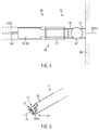
- Fig. 4 shows a plan view of an embodiment of fasteners 73 of an axle clutch 57 of the drive aid 1 in an operating position 13.
- the axle extensions 51 of the wheelchair wheels 39 have been extended by tubular adapter 52.
- the adapters 52 can be attached to the wheelchair 3, inter alia, by welding or screwing. On this adapter 52, the axle strut 53 of the coupling device 5 is placed.
- axle strut 53 The ends 71 of the axle strut 53 are semi-tubular shaped to fit onto the tubular adapters 52.
- sliding elements 74 In the interior of the axle strut 53 are sliding elements 74 as locking elements 78 which are inserted in a coupling position 70 in the adapter 52 and thereby lock the drive aid 1 on the wheelchair 3.
- a mounting position 68 These locking elements are pushed back into the axle strut 53, so that they no longer engage in the adapter 52, whereby the coupling device 5 is released from the wheelchair 3.
- the locking elements 78 are connected via an actuating device with the support 11 of the seat 9.
- Fig. 5 shows as an exemplary embodiment, the schematic representation of a fastener 73 with a locking element 78, which is formed by a rotary member 77.
- the fastening element 73 is shown in the coupling position 70.
- the rotary member 77 is rotatable about the longitudinal axis 79 of the axle strut 53 and has a sleeve 81. In the assembly position 68, the rotary member 77 is rotated so that the sleeve 81 is opened and fits into the semi-tubular end 71 of the axle strut 53. The coupling device 5 can then be placed on the adapter 52.
- the rotary member 77 can be transferred by rotation in the coupling position 70.
- the sleeve 81 engages around the adapter 52, so that the coupling device 5 is locked to the wheelchair 3.
- the drive aid 1 is then connected to the wheelchair 3.
- the rotary members 77 can be connected to an actuator 64. If the seat 9 is transferred into the transport position 67, the rotary element 77 is moved into the assembly position 68 and the drive aid 1 is released from the wheelchair 3. If the seat 9, however, transferred to the operating position 13, the rotary member 77 is moved to the coupling position 70 and the drive aid 1 locked to the wheelchair 3.
Landscapes
- Health & Medical Sciences (AREA)
- Life Sciences & Earth Sciences (AREA)
- Animal Behavior & Ethology (AREA)
- General Health & Medical Sciences (AREA)
- Public Health (AREA)
- Veterinary Medicine (AREA)
- Engineering & Computer Science (AREA)
- Chemical & Material Sciences (AREA)
- Combustion & Propulsion (AREA)
- Transportation (AREA)
- Mechanical Engineering (AREA)
- Nursing (AREA)
- Motorcycle And Bicycle Frame (AREA)
- Carriages For Children, Sleds, And Other Hand-Operated Vehicles (AREA)
Abstract
Description
- Die Erfindung betrifft eine separate Antriebshilfe für rollbare Personen- oder Lastenträger, insbesondere für Rollstühle, mit einem Antriebsmotor, wenigstens einem Antriebsrad, wenigstens einem Sitz für einen Fahrer, und einer Kupplungseinrichtung, durch die die Antriebshilfe an dem Personen- oder Lastenträger wiederholt lösbar befestigbar ist, wobei die Kupplungseinrichtung ein Gelenk aufweist, das zwischen der Kupplungseinrichtung und dem Antriebsrad angeordnet ist.
- Die vorliegende Erfindung eignet sich für den Antrieb von verschiedensten Lastenträgern wie zum Beispiel Werkstattwagen, Aktenwagen oder Handwagen. Der Übersichtlichkeit halber wird die vorliegende Erfindung an einem Rollstuhl beschrieben, ohne dabei die Verwendung an anderen Rollwagen auszuschließen.
- Externe Antriebshilfen für Rollstühle sind allgemein bekannt. In der Regel werden elektrische Antriebsaggregate an den großen Rollstuhlantriebsrädern oder unterhalb des Rollstuhls angebracht. Rollstuhlantriebshilfen, die zur Beförderung einer Begleitperson dienen, sind in der Regel fahrradartig konstruiert und entsprechend sperrig. Dies ist von großem Nachteil, wenn Rollstuhl und Antriebshilfe gemeinsam zum Beispiel in einem Kofferraum verstaut werden sollen. Kompakte Antriebshilfen, auf denen ein Fahrer mitfahren kann und für die ein elektrischer Antrieb vorgesehen ist, sind nur wenige bekannt. Die bekannten Vorrichtungen weisen allerdings Nachteile auf, welche bei der erfindungsgemäßen Vorrichtung nicht auftreten.
- Die Schubeinrichtung aus
DE 20 2006 014 217 U1 nutzt ein Einrad, welches mittels einer Schubstange an einer Querstrebe am Rollstuhlrahmen befestigt wird. Die Querstrebe wird dabei mittels Klemmverschlüssen an den Vertikalrohren des Rollstuhlrahmens befestigt. Zur Verbesserung der Nachlaufeigenschaften ist der Sattel gegenüber dem Antriebsrad versetzt. Das Gespann dieser Druckschrift dürfte recht schwergängig sein. - Die Vorrichtung zum Zwecke des Anschiebens aus
EP 1 364 634 A2 weist einen brettförmigen Hauptkörper auf. Zur Befestigung des Hauptkörpers am Rollstuhl werden an Letzterem zwei Querbretter an die unteren Endrohre des Rollstuhlrahmens angebracht. Zwischen diese wird dann das vordere Ende des Hauptkörpers geklemmt und durch einen Bolzen mit diesem verbunden. Dieser Bolzen stellt zugleich ein Drehgelenk dar und bildet die Lenkachse des Gefährts. Auch dieses Gefährt erfordert erhebliche Kräfte beim Lenken und ist nur eingeschränkt manövrierfähig. - Es ist also die Aufgabe der Erfindung, eine externe Antriebshilfe für rollbare Personen- oder Lastenträger bereitzustellen, die im Gespann mit dem Rollstuhl eine agile Handhabung ermöglichen soll, so dass auch alte Personen die Antriebshilfe nutzen können, und die leicht am Personen- oder Lastenträger zu befestigen ist.
- Diese Aufgabe wird für die eingangs genannte separate Antriebshilfe dadurch gelöst, dass im am Personen- oder Lastenträger montierten Zustand der Antriebshilfe das Gelenk mit einer Achse des Personen- oder Lastenträgers fluchtet.
- Die erfindungsgemäße Lösung kann durch verschiedene, jeweils für sich vorteilhafte, beliebig miteinander kombinierbare Ausgestaltungen weiter verbessert werden. Auf diese Ausgestaltungsformen und die mit ihnen verbundenen Vorteile ist im Folgenden eingegangen, wobei die konstruktiven Maßnahmen und deren Wirkungen lediglich beispielhaft für eine Antriebshilfe an einem Rollstuhl beschrieben sind. Selbstverständlich kann die Antriebshilfe auch an anderen rollbaren Wagen, wie zum Beispiel die anfangs erwähnten Werkstatt- oder Aktenwagen, verwendet werden.
- Die erfindungsgemäße Antriebshilfe kann in einer Ausgestaltung im Wesentlichen aus einem Körper, welcher das Antriebsaggregat enthält, und einem Gestänge, das die Verbindung zum Rollstuhl herstellt, bestehen. Am Körper der Antriebshilfe können sich das Antriebsrad bzw. die Antriebsräder, wenigstens ein Sitz für einen Fahrer sowie seitliche Fußauflagen befinden.
- In einer besonders vorteilhaften Ausführung kann die Antriebshilfe nur ein einziges Rad besitzen, welches gleichzeitig das Antriebsrad der Antriebshilfe und damit des kombinierten Gefährts darstellt. Alternativ kann die Antriebshilfe auch zwei Räder besitzen, insbesondere zwei nebeneinander positionierte Räder, die zusammen ein Doppelrad bilden.
- Die Sitzgelegenheit für den Fahrer kann über dem Antriebsrad positioniert sein, so dass die Gewichtskraft des Fahrers über das Antriebsrad in den Boden geleitet wird. Dies ist vorteilhaft, da eine zu starke Belastung des Rollstuhls mit dem Gewicht des Fahrers vermieden wird. Als Sitzgelegenheit kann zum Beispiel ein Fahrradsattel verwendet werden. Die Sitzgelegenheit kann höhenverstellbar sein, um an die Größe des Fahrers angepasst zu werden. Die Sitzgelegenheit kann von einer Stütze getragen sein, deren Achse in Schwerkraftrichtung verlängert die Achse des Antriebsrads schneidet. Dabei können Abweichungen der Achsen bis zu 2 cm tolerierbar sein. In einer besonders vorteilhaften Ausführung kann die Sitzgelegenheit einklappbar sein, um die Antriebshilfe platzsparend verstauen zu können. Sie kann dann zum Beispiel im Kofferraum eines Pkws transportiert werden.
- Zwischen dem Sitz für den Fahrer und der Kupplungseinrichtung kann die Antriebshilfe seitliche Fußauflagen für den Fahrer aufweisen. Diese Fußauflagen können auch als Fußhebel ausgebildet sein, mit denen Antriebskraft und Bremskraft gesteuert werden. Die Fußhebel können als Wippe ausgestaltet sein, deren längeres Ende in Fahrtrichtung weist und als Auflage für den Vorfuß des Fahrers dient, und deren kürzeres Ende entgegen die Fahrtrichtung weist und als Auflage für die Ferse des Fahrers dient. Die Größe der Fußauflagen kann gängigen Schuhgrößen entsprechen, wobei die Länge bevorzugt zwischen 15 und 35 cm. betragen kann.
- Die Wippen können so angeordnet sein, dass die Füße des Fahrers auf diesen ohne Anstrengung für den Fahrer ruhen können. Aus dieser Ruhelage heraus können die Wippen als Fußhebel leichtgängig betätigt werden. Die Auflage der Füße und die Betätigung der als Fußhebel ohne Kraftaufwand sind wichtige Eigenschaften für die Nutzung der Antriebshilfe durch ältere Personen.
- An handelsüblichen Faltrollstühlen sind die großen Antriebsräder in der Regel einzeln aufgehängt. Die Achsen der beiden einzelnen Räder setzen sich dabei ein Stück weit nach innen fort. An diesen Achsfortsätzen kann die Kupplungseinrichtung angebracht werden. In einer besonders vorteilhaften Ausführung können diese Achsfortsätze zum Beispiel durch ein Rohr oder ein Gestänge miteinander verbunden werden, so dass eine einzige Achse entsteht. Die Verbindung stellt dann eine Achskupplung dar. Diese Achskupplung kann im Wesentlichen ein Teil der Kupplungseinrichtung sein.
- Die Antriebshilfe kann zwischen der Kupplungseinrichtung und dem Antriebsrad ein Gelenk aufweisen, das mit einer Radachse des Rollstuhls fluchtet. Dieses Gelenk kann zwei Gelenkachsen aufweisen, wobei das Gelenk in zwei Freiheitsgraden beweglich sein kann. Die beiden Gelenkachsen können sich bevorzugt schneiden. Die Kupplungseinrichtung kann eine quer zur Fahrtrichtung weisende Achsstrebe und eine zwischen dem Gelenk und dem Antriebsrad in Fahrtrichtung weisende Schubstange aufweisen. An der Mitte der Achsstrebe kann die Schubstange der Antriebshilfe angebracht sein, so dass ein T-förmiges Gestänge entsteht. Die Achsstrebe kann sich durchgängig zwischen den Achsfortsätzen des Rollstuhls erstrecken.
- Die Achsstrebe kann von der Schubstange durchsetzt sein. In dem Bereich dieser Durchsetzung kann eine Gelenkachse angeordnet sein.
- Die Achsstrebe kann drehbar mit den Achsfortsätzen verbunden sein. Die Schubkraft der Antriebshilfe wirkt in diesem Fall über das Gestänge auf die Achsen der Rollstuhlräder. Im Schnittbereich der Schubstange und der Achsstrebe kann sich das Gelenk befinden, so dass das Gefährt lenkbar ist und auch Unterschiede in der Neigung des Untergrunds ausgleichen kann.
- Die Drehachse und die Schwenkachse des Gelenks können möglichst nah an der Achse der beiden Rollstuhlräder liegen. Bevorzugt schneidet die Drehachse des Gelenks die Achse der Rollstuhlräder, wodurch eine leichte Lenkung des kombinierten Gefährts aus Rollstuhl und Antriebshilfe möglich wird. Konstruktions- und fertigungsbedingte Abweichungen bis zu 4 cm können dabei tolerierbar sein.
- Die Schwenkachse des Gelenks kann mit der Achse der Rollstuhlräder übereinstimmen. Dabei können konstruktions- und fertigungsbedingte Abweichungen bis zu 2 cm tolerierbar sein. Diese Art der Befestigung der Antriebshilfe an der Achse der Rollstuhlräder führt zu einer vorteilhaften Kraftübertragung zwischen Antriebshilfe und Rollstuhl. Es werden keine Kippbewegungen wie bei anderen Antriebshilfen im Stand der Technik induziert. Da die Antriebskraft nicht über den Rahmen übertragen wird, entstehen keine Verluste durch Bewegung oder Verformungen des Rahmens. Die Art der Befestigung ermöglicht es, die Antriebshilfe auch bei bereits vorhandenen Rollstühlen nachzurüsten.
- Ein Einklappmechanismus für die Sitzgelegenheit kann so gestaltet sein, dass die Bewegung der Sitzgelegenheit über eine Betätigungseinrichtung, bestehend aus Kraftübertragungselementen, wie Gestänge oder Bowdenzüge, auf eine Kupplungseinrichtung der Antriebshilfe übertragen wird. So kann zum Beispiel eine Verriegelung am Rollstuhl ausgelöst werden, die die Antriebshilfe am Rollstuhl ankuppelt, wenn die Sitzgelegenheit aufgeklappt wird, und wieder löst, wenn die Sitzgelegenheit eingeklappt wird.
- Zur wiederholt lösbaren Befestigung der Antriebshilfe am Rollstuhl, kann die Kupplungseinrichtung Adapter aufweisen, die an die Achsfortsätze der einzeln aufgehängten Räder angebracht werden. Die Adapter können rohrförmige Verlängerungen sein, die fest mit den Achsfortsätzen verbunden werden. Die Achsstrebe der Kupplungseinrichtung kann komplementär zu den Achsfortsätzen ausgebildet sein. Die Achsstrebe der Kupplungseinrichtung kann in einer Ausführungsform an ihren Enden in axialer Richtung halbrohrförmig sein, so dass sie mit diesen Enden auf die Achsverlängerungen aufgelegt werden kann.
- Die Achsstrebe kann Befestigungselemente aufweisen, die komplementär zu den Achsfortsätzen ausgestaltet sind. Die Befestigungselemente können Sperrelemente aufweisen, wobei die Sperrelemente aus einer Montagestellung, in der sie von den Achsfortsätzen gelöst sind, in eine Kupplungsstellung bewegbar sein können, in der sie an den Achsfortsätzen verriegelt sind.
- Die Sperrelemente können mit einer Betätigungseinrichtung verbunden sein und durch die Betätigungseinrichtung zwischen Montagestellung und Kupplungsstellung bewegbar sein.
- In einer Ausführungsform können sich Befestigungselemente wie z.B. Bolzen oder Stifte in der Achsstrebe befinden, die beweglich sind und sich mit je einem Ende in die rohrförmigen Achsverlängerungen einschieben lassen. Die Befestigungsorgane können sich dann jeweils mit einem Ende in der Achsstrebe und mit dem anderen Ende in dem Halteorgan befinden, so dass die Antriebshilfe am Rollstuhl verriegelt ist.
- In einer weiteren Ausführungsform können die Befestigungselemente als drehbare Manschetten ausgebildet sein, die sich im geöffneten Zustand in die halbrohrförmigen Enden der Achsstrebe einfügen, so dass diese auf die Achsfortsätze aufgelegt werden können. Bei einer Drehung der Manschetten können diese dann die Achsfortsätze umgreifen und dadurch die Antriebshilfe am Rollstuhl befestigen.
- In einer besonders vorteilhaften Ausführung können die Befestigungsorgane mit der Betätigungseinrichtung verbunden sein. Ein Aufklappen des Sitzes kann dann die Befestigungsorgane an den Achsfortsätzen verriegeln, so dass die Antriebshilfe am Rollstuhl befestigt ist. Die Antriebshilfe befindet sich in diesem Fall in einer Betriebstellung.
- Der Sitz kann aus einer Betriebsstellung in eine Transportstellung beweglich sein, wobei die Kubatur der Antriebshilfe in dieser Transportstellung kleiner als in der Betriebsstellung ist. Die Betätigungseinrichtung kann bedienungsseitig mit dem Sitz gekoppelt sein, wobei in der Transportstellung die Sperrelemente über die Betätigungseinrichtung in die Montagestellung überführt sind, so dass die Antriebshilfe vom Personen- oder Lastenträger gelöst ist und in der Betriebsstellung über die Betätigungseinrichtung in die Kupplungsstellung überführt sind, in der die Antriebshilfe am Personen- oder Lastenträger befestigt ist.
- Ein Einklappen des Sitzes kann die Befestigungsorgane von den Halteorganen trennen, wodurch die Antriebshilfe vom Rollstuhl gelöst wird und sich in einer Transportstellung befindet.
- Die Antriebshilfe kann einen Ständer besitzen, der die Antriebshilfe aufstützt, wenn diese nicht am Rollstuhl befestigt ist. Dieser Ständer kann einklappbar sein, um ihn am Körper der Antriebshilfe anzulegen, wenn er nicht benötigt wird.
- Zur Lenkung des kombinierten Gefährts aus Rollstuhl und Antriebhilfe können die Rollstuhlhaltegriffe verwendet werden. Es ist dann keine zusätzliche Lenkvorrichtung notwendig. An der Schubstange der Antriebshilfe kann der Abstand zwischen Antriebshilfe und Rollstuhl verändert werden. Dadurch kann der Abstand der Haltegriffe zum Fahrer auf die Körpergröße und Armlänge des Fahrers eingestellt werden, so dass dieser die Haltegriffe bequem erreichen und sicher halten kann.
- Eine vorteilhafte Ausführung der Antriebshilfe kann einen Elektromotor als Antrieb und einen Akkumulator als Energieträger nutzen. Alternativ kann zum Beispiel statt eines Akkumulators eine Brennstoffzelle verwendet werden oder anstelle eines Elektromotors ein Verbrennungsmotor. Bei der Ausführung mit Elektromotor und Akkumulator kann die Aufladung des Akkumulators direkt am Gerät über eine Buchse am Gehäuse erfolgen, oder der Akkumulator kann entnehmbar sein, um ihn an einem Ladegerät zu laden.
- Die Antriebseinheit kann einen Antriebsmotor mit einem Untersetzungsgetriebe, insbesondere mit einem Schneckengetriebe aufweisen. Die Geschwindigkeit der Antriebshilfe und des kombinierten Gefährts aus Rollstuhl und Antriebshilfe kann zulassungsbedingt gedrosselt sein, insbesondere auf eine Schrittgeschwindigkeit von 6 km/h.
- Die Antriebshilfe kann eine Sicherheitseinrichtung aufweisen, durch die eine Anfahrbeschleunigung begrenzt ist. Die Begrenzung der Anfahrbeschleunigung kann insbesondere durch eine Drehmomentsbegrenzung erflogen. Dadurch ist eine Beschleunigung möglich, die für alte oder kranke Personen eine sichere Fahrweise erlaubt.
- Im Folgenden ist die Erfindung beispielhaft anhand von Ausführungsbeispielen mit Bezug auf die Zeichnungen erläutert.
- Es zeigen:
- Fig. 1
- eine schematische Darstellung eines Ausführungsbeispiels einer erfindungsgemäßen Antriebshilfe an einem Rollstuhl in Seitenansicht;
- Fig. 2
- das Ausführungsbeispiel aus
Fig. 1 in der Draufsicht; - Fig. 3
- eine schematische Darstellung des Ausführungsbeispiels aus
Fig. 1 , vom Rollstuhl abgekoppelt in einer Transportstellung; - Fig. 4
- eine schematische Draufsicht eines Befestigungsorgans an einer Achsstrebe;
- Fig. 5
- ein weiteres Ausführungsbeispiel für ein Befestigungselement an einer Achsstrebe.
-
Fig. 1 zeigt eine separate Antriebshilfe 1, verbunden mit einem Rollstuhl 3 in einer Betriebsstellung 13. Die Antriebshilfe 1 ist mit ihrer Kupplungseinrichtung 5 am rollstuhlseitigen Ende der Schubstange 7 am Rollstuhl 3 befestigt. - Antriebshilfe 1 und Rollstuhl bilden zusammen das kombinierte Gefährt 43.
- In dieser Betriebsstellung 13 sind der Sitz 9 und die dazugehörige Stütze 11 aufgeklappt. Der Sitz 9 befindet sich über dem Antriebsrad 21, wobei die Längsachse 15 in Schwerkraftrichtung 17 verlängert, die Radachse 19 des Antriebsrades 21 schneidet. Dabei sind konstruktions- und fertigungsbedingte Abweichungen der Längsachse 15 der Stütze 11 und der Radachse 19 des Antriebsrades 21 bis zu 2 cm tolerierbar. Die Stütze 11 ist durch Befestigungsorgane 23 mit dem Körper 25 der Antriebshilfe 1 unverlierbar verbunden.
- Am Körper 25 der Antriebshilfe 1 befinden sich paarweise Fußauflagen 27. Diese Fußauflagen 27 befinden sich zwischen dem Sitz 9 für den Fahrer und der Kupplungseinrichtung 5 seitlich am Körper 25 der Antriebshilfe 1. Die Fußauflagen 27 sind durch Befestigungsorgane 28 mit dem Körper 25 der Antriebshilfe 1 unverlierbar verbunden. Sie dienen zur Auflage der Füße des Fahrers während der Fahrt. Breite und Länge der Fußauflagen 27 sind and die Schuhgröße einer durchschnittlich großen Person angepasst, so dass jeweils der gesamte Fuß des Fahrers aufgelegt werden kann. Dies erlaubt eine bequeme und sichere Sitzhaltung und eine entspannte Fahrweise, was insbesondere für ältere Personen besonders vorteilhaft ist.
- Die Fußauflagen 27 besitzen die Form einer Wippe mit einem längeren Ende 33 und einem kürzeren Ende 31. Das längere Ende 33 weist in Fahrtrichtung 29 und dient zur Auflage des Vorfußes des Fahrers, das kürzere Ende 31 weist entgegen die Fahrtrichtung 29 und dient zur Auflage der Ferse des Fahrers.
- Die wippenförmige Fußauflage 27 ist um eine quer zur Fahrtrichtung weisende Achse in zwei Richtungen schwenkbar. Die Schwenkachse fällt bevorzugt mit der Achse des Befestigungselements 28 zusammen. Die Fußauflagen 27 sind als Fußhebel ausgestaltet, mit denen Antriebskraft und Bremskraft steuerbar sind. Ein Herunterdrücken des vorderen Endes 33 der Fußauflage 27 kann z. B. die Stärke der Antriebskraft steuern. Ein Druck auf das hintere Ende 31 der Fußauflage 27 kann die Bremsen des Gefährts 43 betätigen. Der Schwenkbereich der Fußauflagen 27 ist auf einen Bereich begrenzt, der die Ausführung der Steuerfunktionen erlaubt.
- Die Oberseite der Fußauflagen 27 ist im Wesentlichen plan ausgestaltet. Sie kann mit einer Struktur oder einer Beschichtung versehen sein, die rutschmindernde Eigenschaften aufweist, um ein Abrutschen eines Fußes während der Fahrt zu verhindern. Dies verbessert die Sicherheit für den Fahrer.
- Die Fußauflagen 27 können aus einem Metall gefertigt sein. Es können aber auch, bei hinreichender Festigkeit, andere Materialien wie z.B. Kunst- oder Verbundstoffe oder Holz verwendet werden.
- Der Durchmesser 35 des Antriebsrades 21 ist bevorzugt kleiner als die Hälfte des Durchmessers 37 der Rollstuhlräder 39 des Rollstuhls 3. Das Antriebsrad 21 ist unverlierbar mit dem Körper 25 der Antriebshilfe 1 verbunden und befindet sich zu einem Teil innerhalb des Körpers 25. dadurch wird eine Berührung des Fahrers mit dem Antriebsrad 21 verhindert. Im Inneren des Körpers 25 der Antriebshilfe 1 befinden sich außerdem die Antriebseinheit, bestehend aus einem Elektromotor und einem Energieträger, wie z. B. einem Akkumulator.
- Die Haltegriffe 41 des Rollstuhls 3 dienen als Haltegriffe für den Fahrer und gleichzeitig als Lenkergriffe für das kombinierte Gefährt 43 aus Rollstuhl 3 und Antriebshilfe 1. Der Fahrer nimmt dadurch eine sichere Haltung auf der Antriebshilfe 1 ein und kann das Gefährt 43 bequem und leichtgängig lenken.
-
Fig. 2 zeigt das Ausführungsbeispiel ausFig. 1 in der Betriebsstellung 13 in der Draufsicht. Zur übersichtlicheren Darstellung sind vom Rollstuhl 3 nur die zur Beschreibung notwendigen Elemente dargestellt. - Bei handelsüblichen Faltrollstühlen sind die Räder 39 einzeln aufgehängt. Die beiden Räder 39 bilden das Räderpaar 40. Die Achsen 45 der Räder 39 durchstoßen die Rohre 47 des Rollstuhlrahmens 49 und werden zur Befestigung ein Stück weit nach innen fortgesetzt. An diesen Achsfortsätzen 51 wird die Kupplungseinrichtung 5 der Antriebshilfe 1 unverlierbar befestigt. Rollstuhl und Antriebshilfe 1 bilden dann gemeinsam das Gefährt 43. Die Kupplungseinrichtung 5 wird im Wesentlichen aus einer quer zur Fahrtrichtung 29 weisenden Achsstrebe 53 gebildet.
- Die Achsstrebe 53 ist im Wesentlichen rohrförmig ausgebildet. Sie ist unverlierbar über eine Achskupplung 57 mit den Achsfortsätzen 51 verbunden. Lässt sich die Achsstrebe 53 nicht direkt an den Achsfortsätzen 51 befestigen, kann die Kupplungseinrichtung 5 Adapter 52 aufweisen, die zunächst an den Achsfortsätzen 51 angebracht werden, um eine Befestigung der Achsstrebe 53 zu ermöglichen.
- Die Kupplungseinrichtung 5 bildet also eine gemeinsame starre Achse der beiden Rollstuhlräder 39. Dies erhöht die Stabilität des Gefährts 43 und verbessert die Fahreigenschaften. Die Schubkraft der Antriebshilfe 1 wird über diese Achse auf die Rollstuhlräder 39 übertragen.
- Die Achsstrebe 53 ist mit den Rollstuhlradachsen 45 schwenkbar verbunden, so dass die Achse der Achsstrebe 53 eine Schwenkachse 59 des kombinierten Gefährts 43 bildet. Die Achsstrebe 53 ist bevorzugt schwenkbar mit den Achsfortsätzen 51 verbunden. Dann fallen die Schwenkachse 59 des Gefährts 43 und die gemeinsame Achse 61 der Rollstuhlräder 39 zusammen. Diese Position der Schwenkachse 59 erlaubt es, die Fahreigenschaften des Gefährts 43 insbesondere beim Überwinden von kleinen Hindernissen oder beim Befahren von Steigungen wesentlich zu verbessern.
- Wird dagegen die Achsstrebe 53 nicht schwenkbar mit den Achsfortsätzen 51 verbunden, sondern unbeweglich am Rollstuhl 3 befestigt, kann die Verbindung der Schubstange 7 zur Achsstrebe 53 schwenkbar ausgestaltet sein. In diesem Fall sind konstruktionsbedingte Abweichungen der Lage der Schwenkachse 59 zur Achse 61 der Räder 39 bis zu 2 cm tolerierbar.
- Die Schubstange 7 ist an ihrem in Fahrtrichtung 29 weisenden Ende mit der Kupplungseinrichtung 5 verbunden. Die Achsstrebe 53 besitzt dazu eine Aufnahme 54. An dieser Aufnahme 54 ist sie von der Schubstange 7 durchsetzt. Die Schubstange 7 ist durch ein Befestigungselement 63 unverlierbar mit der Achsstrebe 53 verbunden. Schubstange 7 und Achsstrebe 53 bilden zusammen ein im Wesentlichen T-förmiges Gestänge 55.
- Die Verbindung von Schubstange 7 zur Achsstrebe 53 ist um eine vertikale Achse drehbar ausgestaltet. Die Aufnahme 54 ist als Öffnung gestaltet, deren Größe und Querschnitt der Schubstange angepasst ist und hinreichend groß ist, um eine Bewegung um die vertikale Achse zu erlauben. Diese Achse bildet die Lenkachse 65 des kombinierten Gefährts 43. Die Lenkachse 65 fällt bevorzugt mit der Achse des Befestigungselements 63 zusammen.
- Die Lenkachse 65 schneidet die Achse 61 der Rollstuhlräder 39. Dadurch wird eine besonders leichte Lenkung des kombinierten Gefährts 43 ermöglicht. Konstruktions- und fertigungstechnisch bedingte Abweichungen von Lenkachse 65 und der Achse 61 des Räderpaares von bis zu 4 cm sind dabei tolerierbar.
- Die Verbindung von Schubstange 7 zur Achsstrebe 53 bildet also ein in zwei Achsen drehbares Gelenk 66, wobei sich das Gelenk 66 im Schnittebereich des T-förmigen Gestänges 55 befindet.
- Die Stütze 11 des Sitzes 9 ist gabelförmig und mit den beiden Gabelschenkeln 14 an den Seiten des Körpers 25 der Antriebshilfe 1 durch Befestigungsorgane 23 verbunden.
-
Fig. 3 zeigt die Antriebshilfe 1 in der Transportstellung 67 abgekoppelt vom Rollstuhl 3. Der Sitz 9 und die dazugehörige Stütze 11 sind in dieser Stellung eingeklappt. In dem Ausführungsbeispiel ist das Gestänge 55 so ausgestaltet, dass der Sitz 9 platzsparend eingeklappt werden kann. - Die Antriebshilfe 1 besitzt in der Transportstellung 67 eine kleinere Kubatur als in der Betriebsstellung 13. Sie ist daher platzsparend und leicht zu verstauen, zum Beispiel im Kofferraum eines Pkws.
- In dem Ausführungsbeispiel hat das Einklappen von Sitz 9 und der Stütze 11 über eine Betätigungseinrichtung 64 die Kupplungseinrichtung 5 vom Rollstuhl 3 gelöst. Die Antriebshilfe 1 ist daher vom Rollstuhl 3 abgekoppelt.
- In der dargestellten Transportstellung 67 ruht die Antriebshilfe 1 auf einem Ständer 69, welcher in der Betriebsstellung 13 an den Körper 25 der Antriebshilfe 1 angelegt oder in den Körper 25 eingeschoben werden kann.
- Die gabelförmige Stütze 11 weist eine Querstrebe 12 auf, die die beiden Gabelschenkel 14 miteinander verbindet. Die Querstrebe 12 verleiht der Stütze 11 zusätzliche Stabilität. Die Querstrebe 12 ist als Tragegriff 16 ausgestaltet oder kann einen Tragegriff tragen, so dass die Antriebshilfe 1 in der Transportstellung 67 an diesem Tragegriff 16 angehoben und transportiert werden kann.
-
Fig. 4 zeigt eine Draufsicht auf ein Ausführungsbeispiel von Befestigungselementen 73 einer Achskupplung 57 der Antriebshilfe 1 in einer Betriebsstellung 13. Die Achsfortsätze 51 der Rollstuhlräder 39 sind durch röhrenförmige Adapter 52 verlängert worden. Die Adapter 52 können u. a. durch Verschweißen oder Verschrauben am Rollstuhl 3 angebracht werden. Auf diese Adapter 52 wird die Achsstrebe 53 der Kupplungseinrichtung 5 aufgelegt. - Die Enden 71 der Achsstrebe 53 sind halbrohrförmig ausgestaltet, so dass sie auf die röhrenförmigen Adapter 52 passen. Im inneren der Achsstrebe 53 befinden sich Verschiebelemente 74 als Sperrelemente 78, die in einer Kupplungsstellung 70 in die Adapter 52 eingeschoben sind und dadurch die Antriebshilfe 1 am Rollstuhl 3 verriegeln. In einer Montagestellung 68 werden diese Sperrelemente wieder in die Achsstrebe 53 zurückgeschoben, so dass sie nicht mehr in die Adapter 52 greifen, wodurch die Kupplungseinrichtung 5 vom Rollstuhl 3 gelöst ist.
- Im gezeigten Ausführungsbeispiel sind die Sperrelemente 78 über eine Betätigungseinrichtung mit der Stütze 11 des Sitzes 9 verbunden.
-
Fig. 5 zeigt als Ausführungsbeispiel die schematische Darstellung eines Befestigungselements 73 mit einem Sperrelement 78, das durch ein Drehelement 77 gebildet wird. Das Befestigungselement 73 ist in der Kupplungsstellung 70 dargestellt. - Das Drehelement 77 ist um die Längsachse 79 der Achsstrebe 53 drehbar und besitzt eine Manschette 81. In der Montagestellung 68 ist das Drehelement 77 so gedreht, dass die Manschette 81 geöffnet ist und sich in das halbrohrförmige Ende 71 der Achsstrebe 53 einfügt. Die Kupplungseinrichtung 5 kann dann auf die Adapter 52 aufgelegt werden.
- Das Drehelement 77 kann durch Drehung in die Kupplungsstellung 70 überführt werden. In der Kupplungsstellung 70 greift die Manschette 81 um das den Adapter 52, so dass die Kupplungseinrichtung 5 am Rollstuhl 3 verriegelt ist. Die Antriebshilfe 1 ist dann mit dem Rollstuhl 3 verbunden.
- Auch bei diesem Ausführungsbeispiel können die Drehelemente 77 mit einer Betätigungseinrichtung 64 verbunden werden. Wird der Sitz 9 in die Transportstellung 67 überführt, so wird das Drehelement 77 in die Montagestellung 68 bewegt und die Antriebshilfe 1 vom Rollstuhl 3 gelöst. Wird der Sitz 9 dagegen in die Betriebsstellung 13 überführt, so wird das Drehelement 77 in die Kupplungsstellung 70 bewegt und die Antriebshilfe 1 am Rollstuhl 3 verriegelt.
-
- 1
- Antriebshilfe
- 3
- Rollstuhl
- 5
- Kupplungseinrichtung
- 7
- Schubstange
- 9
- Sitz
- 11
- Stütze
- 12
- Querstrebe
- 13
- Betriebsstellung
- 14
- Gabelschenkel
- 15
- Längsachse der Stütze
- 16
- Tragegriff
- 17
- Schwerkraftrichtung
- 19
- Achse des Antriebsrades
- 21
- Antriebsrad
- 23
- Befestigungsorgan
- 25
- Körper der Antriebshilfe
- 27
- Fußauflage
- 28
- Befestigungsorgane
- 29
- Fahrtrichtung
- 31
- kurzes Ende der Fußauflage
- 33
- langes Ende der Fußauflage
- 35
- Durchmesser des Antriebsrades
- 37
- Durchmesser der Rollstuhlräder
- 39
- Rollstuhlräder
- 40
- Räderpaar
- 41
- Rollstuhlhaltegriffe
- 43
- kombiniertes Gefährt
- 45
- Achsen der Rollstuhlräder
- 47
- Rohr
- 49
- Rollstuhlrahmen
- 51
- Achsfortsätze
- 53
- Achsstrebe
- 54
- Aufnahme
- 55
- Gestänge
- 57
- Achskupplung
- 59
- Schwenkachse
- 61
- Achse des Räderpaares
- 63
- Befestigungselement
- 64
- Betätigungseinrichtung
- 65
- Lenkachse
- 66
- Gelenk
- 67
- Transportstellung
- 68
- Montagestellung
- 69
- Ständer
- 70
- Kupplungsstellung
- 71
- Enden der Achsstrebe
- 73
- Befestigungselemente
- 74
- Verschiebeelement
- 77
- Drehbares Befestigungselement
- 78
- Sperrelement
- 79
- Längsachse der Achsstrebe
- 81
- Manschette
Claims (14)
- Separate Antriebshilfe (1) für rollbare Personen- oder Lastenträger (3), insbesondere für Rollstühle, mit einem Antriebsmotor, wenigstens einem Antriebsrad (21), wenigstens einem Sitz (9) für einen Fahrer, und einer Kupplungseinrichtung (5), durch die die Antriebshilfe (1) an dem Personen- oder Lastenträger (3) wiederholt lösbar befestigbar ist, wobei die Kupplungseinrichtung (5) ein Gelenk (66) aufweist, das zwischen der Kupplungseinrichtung (5) und dem Antriebsrad (21) angeordnet ist, dadurch gekennzeichnet, dass im am Personen- oder Lastenträger (3) montierten Zustand der Antriebshilfe (1) das Gelenk (66) mit einer Radachse (61) des Personen- oder Lastenträgers (3) fluchtet.
- Separate Antriebshilfe (1) nach Anspruch 1, dadurch gekennzeichnet, dass das Gelenk (66) zwei Gelenkachsen aufweist, wobei das Gelenk (66) in zwei Freiheitsgraden bewegbar ist und sich die beiden Gelenkachsen schneiden.
- Separate Antriebshilfe (1) nach Anspruch 1 oder 2, dadurch gekennzeichnet, dass die Antriebshilfe (1) zwischen dem Gelenk (66) und dem Antriebsrad (21) eine in Fahrtrichtung (29) weisende Schubstange (7) aufweist.
- Separate Antriebshilfe (1) nach Anspruch 3, dadurch gekennzeichnet, dass die Kupplungseinrichtung (5) eine quer zur Fahrtrichtung (29) weisende Achsstrebe (53) aufweist.
- Separate Antriebshilfe (1) nach Anspruch 3 oder 4, dadurch gekennzeichnet, dass die Achsstrebe (53) und die Schubstange (7) ein T-förmiges Gestänge (55) bilden.
- Separate Antriebshilfe (1) nach Anspruch 5, dadurch gekennzeichnet, dass sich das Gelenk (66) im Schnittbereich des T-förmigen Gestänges (55) befindet.
- Separate Antriebshilfe (1) nach einem der Ansprüche 1 bis 6, dadurch gekennzeichnet, dass die Achsstrebe (53) komplementär zu Achsfortsätzen (51) einer Achse (61) des Personen- oder Lastenträgers (3) ausgebildet ist.
- Separate Antriebshilfe (1) nach einem der Ansprüche 1 bis 7, dadurch gekennzeichnet, dass die Kupplungseinrichtung (5) mit ihrer Achsstrebe (53) drehbar mit den Achsfortsätzen (51) verbunden ist.
- Separate Antriebshilfe (1) nach einem der Ansprüche 1 bis 8, dadurch gekennzeichnet, dass die Achsstrebe (53) von der Schubstange (7) durchsetzt ist und dass eine Gelenkachse (65) in dem Bereich der Durchsetzung angeordnet ist.
- Separate Antriebshilfe (1) nach einem der Ansprüche 1 bis 9, dadurch gekennzeichnet, dass sich die Achsstrebe (53) durchgängig zwischen den Achsfortsätzen (51) des Personen- oder Lastenträgers (3) erstreckt.
- Separate Antriebshilfe (1) nach einem der Ansprüche 1 bis 10, dadurch gekennzeichnet, dass die Kupplungseinrichtung (5) an den Enden (71) der Achsstrebe (53) Befestigungselemente (73) aufweist, die komplementär zu den Achsfortsätzen (51) ausgestaltet sind.
- Separate Antriebshilfe (1) nach Anspruch 11, dadurch gekennzeichnet, dass die Befestigungselemente (73) Sperrelemente (78) aufweisen, wobei die Sperrelemente (78) aus einer Montagestellung (68), in der sie von den Achsfortsätzen (51) gelöst sind, in eine Kupplungsstellung (70) bewegbar sind, in der sie an den Achsfortsätzen (51) verriegelt sind.
- Separate Antriebshilfe (1) nach Anspruch 12, dadurch gekennzeichnet, dass die Sperrelemente (78) mit einer Betätigungseinrichtung (64) verbunden und durch die Betätigungseinrichtung (64) zwischen Montagestellung (68) und Kupplungsstellung (70) bewegbar sind.
- Separate Antriebshilfe (1) nach Anspruch 13, dadurch gekennzeichnet, dass der Sitz (9) aus einer Betriebsstellung (13) in eine Transportstellung (67) beweglich ist, wobei die Kubatur der Antriebshilfe (1) in der Transportstellung (67) kleiner als in der Betriebsstellung (13) ist, dass die Betätigungseinrichtung (64) bedienungsseitig mit dem Sitz (9) gekoppelt ist, wobei in der Transportstellung (67) die Sperrelemente (78) über die Betätigungseinrichtung (64) in die Montagestellung (68) überführt sind, so dass die Antriebshilfe (1) vom Personen- oder Lastenträger (3) gelöst ist und in der Betriebsstellung (13) über die Betätigungseinrichtung (64) in die Kupplungsstellung (70) überführt sind, in der die Antriebshilfe (1) am Personen- oder Lastenträger (3) befestigt ist.
Applications Claiming Priority (1)
| Application Number | Priority Date | Filing Date | Title |
|---|---|---|---|
| DE102012219689.7A DE102012219689A1 (de) | 2012-10-26 | 2012-10-26 | Separate Antriebshilfe für Rollstühle |
Publications (2)
| Publication Number | Publication Date |
|---|---|
| EP2724697A2 true EP2724697A2 (de) | 2014-04-30 |
| EP2724697A3 EP2724697A3 (de) | 2014-05-21 |
Family
ID=49354494
Family Applications (1)
| Application Number | Title | Priority Date | Filing Date |
|---|---|---|---|
| EP13188217.7A Withdrawn EP2724697A3 (de) | 2012-10-26 | 2013-10-11 | Separate Antriebshilfe für Rollstühle |
Country Status (2)
| Country | Link |
|---|---|
| EP (1) | EP2724697A3 (de) |
| DE (1) | DE102012219689A1 (de) |
Citations (2)
| Publication number | Priority date | Publication date | Assignee | Title |
|---|---|---|---|---|
| EP1364634A2 (de) | 2001-08-31 | 2003-11-26 | Bernd Rothenburg | Einrichtung zur Kopplung eines Rolleraggregates an ein Rollstuhlvehikel zum Zwecke des Anschiebens oder, im Falle, dass das vordere Rollstuhlvehikel durch körperliche oder motorische Antriebskraft angetrieben wird, dieses durch Traktion hinter sich her führt |
| DE202006014217U1 (de) | 2006-09-16 | 2006-11-23 | Kappner, Kurt, Dipl.-Ing. (FH) | Schubeinrichtung für Rollstühle |
Family Cites Families (9)
| Publication number | Priority date | Publication date | Assignee | Title |
|---|---|---|---|---|
| US2482585A (en) * | 1946-01-15 | 1949-09-20 | Gerhard G Hauptman | Combination bicycle and baby carriage |
| US3524512A (en) * | 1968-02-21 | 1970-08-18 | Elton L Voeks | Self-propelled driving and steering truck for shopping carts |
| US3575250A (en) * | 1968-12-23 | 1971-04-20 | Battery Power Unit Co Inc | Self-propelled electric vehicle and battery mount |
| DE8710562U1 (de) * | 1986-07-31 | 1987-10-29 | Schramm, Siegfried, 3208 Giesen, De | |
| US4771840A (en) * | 1987-04-15 | 1988-09-20 | Orthokinetics, Inc. | Articulated power-driven shopping cart |
| DE3714106A1 (de) * | 1987-04-28 | 1988-11-10 | Helmut Prof Dr Reichmann | Kupplungsanschluss fuer kombinationsfahrzeuge aus rollstuhl und fahrrad |
| US4770431A (en) * | 1987-08-05 | 1988-09-13 | Helmut Kulik | Snap on wheel chair bicycle converter |
| IL121778A (en) * | 1997-09-16 | 2001-01-11 | Hillel Hillel | Lift transit vehicle |
| JP2001346836A (ja) * | 2000-06-07 | 2001-12-18 | Genzo Nishigori | 介護者操作電動移動車 |
-
2012
- 2012-10-26 DE DE102012219689.7A patent/DE102012219689A1/de not_active Withdrawn
-
2013
- 2013-10-11 EP EP13188217.7A patent/EP2724697A3/de not_active Withdrawn
Patent Citations (2)
| Publication number | Priority date | Publication date | Assignee | Title |
|---|---|---|---|---|
| EP1364634A2 (de) | 2001-08-31 | 2003-11-26 | Bernd Rothenburg | Einrichtung zur Kopplung eines Rolleraggregates an ein Rollstuhlvehikel zum Zwecke des Anschiebens oder, im Falle, dass das vordere Rollstuhlvehikel durch körperliche oder motorische Antriebskraft angetrieben wird, dieses durch Traktion hinter sich her führt |
| DE202006014217U1 (de) | 2006-09-16 | 2006-11-23 | Kappner, Kurt, Dipl.-Ing. (FH) | Schubeinrichtung für Rollstühle |
Also Published As
| Publication number | Publication date |
|---|---|
| EP2724697A3 (de) | 2014-05-21 |
| DE102012219689A1 (de) | 2014-04-30 |
Similar Documents
| Publication | Publication Date | Title |
|---|---|---|
| WO2019101635A1 (de) | Rollator mit elektrischem antrieb | |
| EP3145800B1 (de) | Einspuriger tretroller | |
| EP2627554B1 (de) | Durch gewichtsverlagerung steuerbares fahrzeug mit zweigeteiltem fahrbrett | |
| DE102016101870A1 (de) | Lastenrad | |
| EP3488839A1 (de) | Rollator mit elektrischem antrieb | |
| WO2020127972A1 (de) | Elektrofahrzeug mit transportfunktion und verfahren zu dessen zustandsänderung | |
| EP3652052B1 (de) | Tretroller und verfahren zum bedienen eines rollers | |
| EP2895129B1 (de) | Rollstuhl | |
| EP2724698B1 (de) | Separate Antriebshilfe für Rollstühle | |
| DE3303218A1 (de) | Dreirad zur befoerderung von personen und guetern | |
| EP0085091A1 (de) | Rollstuhl-zuggerät | |
| EP3569214A1 (de) | Fahrzeug | |
| DE102017205080B4 (de) | Kraftfahrzeug mit mobilem Fahrzeugsitz und mobiler Fahrzeugsitz | |
| DE102015105321A1 (de) | Zusammenfaltbares Zweirad und Verfahren zum Zusammenfalten eines Zweirads | |
| DE2724553C2 (de) | Elektrisch angetriebener, als Selbstfahrer ausgebildeter Krankenfahrstuhl | |
| DE102008059605A1 (de) | Modulares System für zum täglichen Gebrauch teilzerlegbare Fahrzeuge | |
| EP2724697A2 (de) | Separate Antriebshilfe für Rollstühle | |
| DE102011010909A1 (de) | Bewegliche Beinablagen zum Auf- und Abständern oder zur Sitzabsenkung eines kurvenneigbaren Zwei- oder Dreirades | |
| DE102012015651A1 (de) | Nutzfahrzeug | |
| DE102009024522A1 (de) | Baukastensystem für teilzerlegbare Fahrzeuge | |
| DE102016122518B4 (de) | Zusammenklappbares Fahrzeug | |
| DE102019126096A1 (de) | Fahrzeug | |
| DE202006014217U1 (de) | Schubeinrichtung für Rollstühle | |
| DE202010015482U1 (de) | Gymnastik-Laufrad mit Elektroantrieb | |
| DE202009001418U1 (de) | Gymnastik-Laufrad |
Legal Events
| Date | Code | Title | Description |
|---|---|---|---|
| PUAL | Search report despatched |
Free format text: ORIGINAL CODE: 0009013 |
|
| PUAI | Public reference made under article 153(3) epc to a published international application that has entered the european phase |
Free format text: ORIGINAL CODE: 0009012 |
|
| 17P | Request for examination filed |
Effective date: 20131011 |
|
| AK | Designated contracting states |
Kind code of ref document: A2 Designated state(s): AL AT BE BG CH CY CZ DE DK EE ES FI FR GB GR HR HU IE IS IT LI LT LU LV MC MK MT NL NO PL PT RO RS SE SI SK SM TR |
|
| AX | Request for extension of the european patent |
Extension state: BA ME |
|
| AK | Designated contracting states |
Kind code of ref document: A3 Designated state(s): AL AT BE BG CH CY CZ DE DK EE ES FI FR GB GR HR HU IE IS IT LI LT LU LV MC MK MT NL NO PL PT RO RS SE SI SK SM TR |
|
| AX | Request for extension of the european patent |
Extension state: BA ME |
|
| RIC1 | Information provided on ipc code assigned before grant |
Ipc: A61G 5/00 20060101ALI20140417BHEP Ipc: A61G 5/10 20060101ALI20140417BHEP Ipc: A61G 5/04 20130101AFI20140417BHEP |
|
| STAA | Information on the status of an ep patent application or granted ep patent |
Free format text: STATUS: THE APPLICATION IS DEEMED TO BE WITHDRAWN |
|
| 18D | Application deemed to be withdrawn |
Effective date: 20141122 |