EP2720591B1 - Duschwanne und verfahren zur herstellung einer duschwanne - Google Patents
Duschwanne und verfahren zur herstellung einer duschwanne Download PDFInfo
- Publication number
- EP2720591B1 EP2720591B1 EP12728367.9A EP12728367A EP2720591B1 EP 2720591 B1 EP2720591 B1 EP 2720591B1 EP 12728367 A EP12728367 A EP 12728367A EP 2720591 B1 EP2720591 B1 EP 2720591B1
- Authority
- EP
- European Patent Office
- Prior art keywords
- shower tray
- pipes
- edge
- heat exchanger
- tubes
- Prior art date
- Legal status (The legal status is an assumption and is not a legal conclusion. Google has not performed a legal analysis and makes no representation as to the accuracy of the status listed.)
- Active
Links
Images


Classifications
-
- A—HUMAN NECESSITIES
- A47—FURNITURE; DOMESTIC ARTICLES OR APPLIANCES; COFFEE MILLS; SPICE MILLS; SUCTION CLEANERS IN GENERAL
- A47K—SANITARY EQUIPMENT NOT OTHERWISE PROVIDED FOR; TOILET ACCESSORIES
- A47K3/00—Baths; Douches; Appurtenances therefor
- A47K3/28—Showers or bathing douches
- A47K3/40—Pans or trays
-
- C—CHEMISTRY; METALLURGY
- C25—ELECTROLYTIC OR ELECTROPHORETIC PROCESSES; APPARATUS THEREFOR
- C25D—PROCESSES FOR THE ELECTROLYTIC OR ELECTROPHORETIC PRODUCTION OF COATINGS; ELECTROFORMING; APPARATUS THEREFOR
- C25D11/00—Electrolytic coating by surface reaction, i.e. forming conversion layers
- C25D11/02—Anodisation
- C25D11/04—Anodisation of aluminium or alloys based thereon
-
- F—MECHANICAL ENGINEERING; LIGHTING; HEATING; WEAPONS; BLASTING
- F28—HEAT EXCHANGE IN GENERAL
- F28D—HEAT-EXCHANGE APPARATUS, NOT PROVIDED FOR IN ANOTHER SUBCLASS, IN WHICH THE HEAT-EXCHANGE MEDIA DO NOT COME INTO DIRECT CONTACT
- F28D7/00—Heat-exchange apparatus having stationary tubular conduit assemblies for both heat-exchange media, the media being in contact with different sides of a conduit wall
- F28D7/08—Heat-exchange apparatus having stationary tubular conduit assemblies for both heat-exchange media, the media being in contact with different sides of a conduit wall the conduits being otherwise bent, e.g. in a serpentine or zig-zag
- F28D7/082—Heat-exchange apparatus having stationary tubular conduit assemblies for both heat-exchange media, the media being in contact with different sides of a conduit wall the conduits being otherwise bent, e.g. in a serpentine or zig-zag with serpentine or zig-zag configuration
-
- F—MECHANICAL ENGINEERING; LIGHTING; HEATING; WEAPONS; BLASTING
- F28—HEAT EXCHANGE IN GENERAL
- F28F—DETAILS OF HEAT-EXCHANGE AND HEAT-TRANSFER APPARATUS, OF GENERAL APPLICATION
- F28F1/00—Tubular elements; Assemblies of tubular elements
-
- F—MECHANICAL ENGINEERING; LIGHTING; HEATING; WEAPONS; BLASTING
- F28—HEAT EXCHANGE IN GENERAL
- F28D—HEAT-EXCHANGE APPARATUS, NOT PROVIDED FOR IN ANOTHER SUBCLASS, IN WHICH THE HEAT-EXCHANGE MEDIA DO NOT COME INTO DIRECT CONTACT
- F28D21/00—Heat-exchange apparatus not covered by any of the groups F28D1/00 - F28D20/00
- F28D21/0001—Recuperative heat exchangers
- F28D21/0012—Recuperative heat exchangers the heat being recuperated from waste water or from condensates
-
- F—MECHANICAL ENGINEERING; LIGHTING; HEATING; WEAPONS; BLASTING
- F28—HEAT EXCHANGE IN GENERAL
- F28F—DETAILS OF HEAT-EXCHANGE AND HEAT-TRANSFER APPARATUS, OF GENERAL APPLICATION
- F28F2275/00—Fastening; Joining
- F28F2275/02—Fastening; Joining by using bonding materials; by embedding elements in particular materials
- F28F2275/025—Fastening; Joining by using bonding materials; by embedding elements in particular materials by using adhesives
Definitions
- the invention relates to the field of shower trays and a method for producing a shower tray according to the preamble of the corresponding independent claims.
- Such a shower tray is made, for example WO 2010/088784 A1 the same applicant.
- the heat exchanger has a flat cover plate as a drainage surface over which wastewater drains.
- the cover plate is formed of chrome steel, forms the bottom of the shower tray and can be molded integrally with the shower tray. Either the plate consists of two layers, one of which is profiled and placed under the other, whereby meandering channels are defined between the plates, or tubes through which water to be heated flows are soldered against a plate.
- DE 44 06 971 shows a shower tray, at the bottom by the welding of pipes or profiles channels are mounted through which flows cold water.
- NL 1031082 shows a heat exchanger below a shower tray, in which pipes are soldered via a narrow web to a drainage surface.
- EP 2 072 930 A2 shows a heated bath or shower tray with a first sheet in contact with wastewater and heating pipes, or with a second plate, wherein there are cavities between the two sheets as heating channels.
- the first sheet may be made of aluminum or an aluminum alloy.
- US 2009/0266105 A1 discloses an aluminum heat exchanger for a refrigerator, in which a tube is fixed by means of spot welding on a plate, and then tubes and plate are protected with a layer of paint.
- WO 2009/030503 describes the production of thermal solar collectors, in which thermal fluid tubes are welded to an absorber sheet with a laser.
- GB2420973 shows a shower tray with heat exchanger with an undercut tub rim, in which an elastic region of an insertable pan bottom snaps.
- a further undercut region of the tub rim can cooperate with projections of the tub bottom, in order to lock or release it upon rotation of the tub bottom.
- a shower tray with a heat exchanger wherein the heat exchanger is disposed below the shower tray for heat recovery from waste water for warming fresh water, wherein a first heat exchanger surface in contact with the waste water and a second heat exchanger surface is in contact with the fresh water, and the first heat exchanger surface forms the bottom or part of the bottom of the shower tray.
- the shower tray is made of aluminum or an aluminum alloy manufactured. As aluminum alloys, metal alloys are considered which have a weight fraction of at least 80% aluminum. In the following, where aluminum is concerned, an aluminum alloy is also meant. It is also possible to manufacture the tub from a material with a thermal conductivity of over 100 W / (mK).
- the second heat exchange surface is formed by tubes, which are connected by welding to the bottom of the shower tray
- the inner diameter of the tubes is kept small, or it is profiled the inside of the tubes, which can be done for example by deforming the tubes from the outside.
- the flow resistance of the tubes increases, which is why several tubes are guided in parallel.
- the length of the tubes is substantially the same.
- the tubes are composite tubes (or dual tubes) having an outer layer of aluminum or an aluminum alloy and an inner layer of copper or a copper alloy.
- copper alloys metal alloys are considered, which account for at least 50% by weight. Have copper. In what follows, where copper is concerned, a copper alloy is also meant.
- a copper tube is welded to the bottom of the aluminum tub, in particular by means of laser welding.
- a weldable anodization layer is formed on the bottom of the tub.
- the shower tray and the outside of the pipes are anodized.
- the tubes are capped to prevent the copper layer in the tubes from being dissolved by the anodizing bath.
- the anodization occurs after welding, whereby the welding process is simplified.
- connecting the pipes with copper connecting elements after anodizing becomes more complicated, since the formation of a galvanic element is to be prevented.
- an edge region of the shower tray has a further or a reinforced coating, in particular a layer produced by powder coating, for example with aluminum oxide, or a lacquer layer.
- a further or a reinforced coating in particular a layer produced by powder coating, for example with aluminum oxide, or a lacquer layer.
- the entire membrane has a coating which permits corrosion protection or wear protection and / or wetting of the surface (hydrophilic coating).
- the shower tray is formed by a forming process, in particular by deep drawing or by hydroforming (hydroforming) or by superplastic deformation. You can also be formed by bending and welding individual sections of the shower tray.
- the combination of hydroforming to form the tub with anodizing as a surface treatment drawing marks on the top of the tub, which arise in a normal forming with punch and die, would have to be reworked or laminated by a material-applying process (coating, painting).
- a material-applying process coating, painting
- a further advantage of the production by means of hydroforming is that the undercut parts can be shaped in a particularly simple manner, ie without the use of slides.
- the shower tray has a lid, and further includes a first edge and a second edge, the first and second edges facing each other, and wherein at the first edge there is an inclined support portion for Supporting the lid is present, and at the second edge of the shower tray, which lies opposite the first edge, there is an undercut edge area. Due to the inclination in the support area of the lid is pressed under load in the undercut area. In the support region, there are preferably no undercut regions and the cover can easily be lifted upwards. In the undercut area, on the other hand, the lid can not be raised without first pulling the lid out of the undercut area in the horizontal direction towards the second edge.
- reinforcement profiles are arranged on the underside of the shower tray. This makes the shower tray thinner and lighter.
- the reinforcing profiles can be welded or glued to the shower tray.
- the reinforcing profiles may have a U-profile and so embrace one or more of the tubes or bridge. This implies that the reinforcing profiles are attached to the shower tray after attaching the tubes.
- the method for producing a shower tray can, in particular when using hydroforming, be carried out repeatedly, with shower trays having differently wide outer edge areas being produced, such outer edge areas adjoining edge areas of a depression of the shower tray. These outer edge areas form a standing surface after installation of the shower tray. So it is with the same mold shower trays for showers with different levels of standing space produced.
- shower tray in this application is also understood as comprising the term “bathtub”. In a further embodiment, therefore, the shower tray is a bathtub.
- the heat exchanger for example, a width between 20cm and 70cm and a length between 80cm and 200cm.
- a pipe spacing between parallel pipes of the heat exchanger is, for example, 1 cm to 5 cm or 2 cm to 5 cm, in particular at least approximately 2.4 cm (measured from center to center of the pipes).
- the tube spacing is in particular less than 7 cm.
- the distances between welding points about 2mm measured from center to center of the welding points
- the welding points themselves have a diameter of less than 2mm, and the pipe diameter is smaller, ie with inner diameters between 4mm and 10mm, especially 4.75mm.
- collecting pieces to which the pipes are connected may be arranged outside the drainage surface.
- the slope of the tank bottom is for example between 3% and 4.5%, in particular 3.5%. This applies to the bottom of the tank in the assembled state. Assuming that the edges of the tub are to be mounted horizontally, this also applies to the angle between the upper edges of the tub and the tub bottom. With this slope, there is a particularly good heat transfer, unexpectedly better than at a smaller angle, such as 2%.
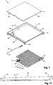
- FIG. 1 shows a shower tray 10 in a first embodiment in an exploded view.
- the shower tray 10 is formed as a heat exchanger 1 by a tub bottom 12, which is covered during the shower of sewage, is thermally conductively connected to tubes 14 through which fresh water is passed.
- the tubes 14 extend over as large a part of the tub bottom 12.
- the fresh water is supplied to the tubes 14 through a supply line 22 and a first claw 21, and there to several (two, three, four, five, six or more) parallel Pipes 14 distributed, flows in the opposite direction to the wastewater or in the same direction through the meandering tubes 14 to a second claw 21.
- the tubes 14 are guided substantially equidistant from each other, whereby a balanced heat transfer takes place over the surface.
- the tubes 14 are spaced apart both in the region in which they extend transversely to the slope of the trough bottom 12 and in the region in which they are parallel to the gradient.
- the distance of the tubes 14 is between 20mm and 30mm, for example 24mm (measured from center to center).
- the sections of the individual tubes 14 between the collecting pieces 21 are all of the same length, so that their flow resistance and thus also their flow rate are essentially the same.
- transitional tube 20 may be arranged for manufacturing reasons.
- the wastewater flows via a slightly inclined cover 4 to one side of the shower tray 10 toward an inlet region 33, and from this in turn, distributed over the width of the trough 12, via the trough bottom 12 to an outlet region 34 and from there a run 35.
- An edge region 32 which preferably leads around the shower tray 10, is in formed at an angle between about 40 ° to 70 ° obliquely.
- height adjustable feet 132 may be present.
- the lid 4 is formed at its lid edge 42 with a corresponding slope. As a result, the edge region 32 forms a cross-sectionally trapezoidal seat for the lid 4 and centers it in the shower tray 10.
- FIG. 2 shows a shower tray in a second embodiment in an exploded view. It is functionally the same elements in a slightly different configuration than in the FIG. 1 in front.
- the tub floor 12 has webs or ribs 31 for reinforcement.
- a metal plate hereinafter referred to as bottom plate 13 is arranged between the tub bottom 12 and the tubes 14 .
- This bottom plate 13 has cutouts 23 which correspond to the position of the ribs 31, ie each cut in the region of a rib 31, so that the bottom plate 13 can be fixed flat on the underside of the tub bottom 12.
- At the edge of the shower tray 10 can be bent down or molded side walls 37.
- FIG. 3 shows a cross section of the structure of a heat exchanger with a shower tray 10 made of aluminum , usually an aluminum alloy.
- the shower tray 10 is preferably made in one piece by a forming process, in particular hydroforming, and / or by cutting, bending and welding;
- the tub bottom 12 is made of this material.
- the tank bottom 12 is overflowed during operation with warm waste water 145.
- Below the trough 12 are tubes 14 with fresh water 144, for example in an arrangement according to the FIG. 1 or 2 , welded directly against the underside of the tub bottom 12, by laser welding.
- Contact areas of welding points 143 have a diameter d of preferably less than 2 mm. For example, the distance between welding points 143 is at least approximately 1mm (along the direction of the tube).
- the distance is the Welding points 143 in the range between 1.5mm and 2.5mm, especially at 2mm (measured from the center of a weld point to the middle of the next weld point, respectively). This results in a better heat transfer: a greater distance degrades the efficiency of the heat exchanger, a smaller distance does not improve it significantly.
- the diameter of a welding point is for example less than 2mm, in particular about 1mm.
- the tubes 14 are made of aluminum or an aluminum alloy. Preferably, they are also coated on the inside, for example with polyethylene (PE).
- the tubes 14 are composite tubes (bimetallic tubes, composite tubes, dual tubes) with an outer wall or outer layer 141 of aluminum or an aluminum alloy and with an inner wall or inner layer 142 of copper or a copper alloy.
- phosphorus deoxidized copper Cu-DHP
- Example composite tubes have a wall thickness of about 0.55 mm aluminum (alloy) and 0.25 mm copper (alloy) with an outer diameter of about 6.5 mm (1/4 "inch, 6.35mm) .
- the inner diameter is about 4.75mm
- the shower tray 10 and thus also the tub bottom 12 and the tubes 14 are anodized (anodized), in particular hard anodized, and thereby Abreibfest and yet thermally conductive.
- the edge of the tub, which is visible next to the lid 14, may be coated or painted in a different color.
- the anodization of composite pipes 14, these are closed at the ends, so that the inner layer of copper is not dissolved in the anodizing.
- FIG. 10 schematically shows shower trays 10 with different variants of outer edge regions 36.
- Such variants can be produced in the same form by forming, in particular hydroforming.
- the shape of the depression of the trough with the trough bottom 12 and the heat exchanger 1 is the same in these variants, an outer edge region 36 adjoining the depression is configured differently widely expanded in one or more directions.
- these outer edge portions 36 are substantially horizontal and form a tread.
- the footprint is 90cm by 90cm (standard size), or 90cm by 120cm, or 90cm by 140cm.
- additional side areas which are bent down to side walls 37 such as in the embodiment of FIGS. 8 and 9 to build.
- the shower tray 10 is made of stainless steel, in particular stainless steel, and tubes 14 are welded copper or a copper alloy.
- stainless steel in particular stainless steel
- tubes 14 are welded copper or a copper alloy.
- such an arrangement has a reduced efficiency as a heat exchanger.
- FIG. 4 shows for better understanding a cross section of the construction of a heat exchanger with a shower tray 10 made of steel , usually made of an enamelled steel.
- the shower tray 10 is preferably made in one piece by a forming process, and / or by cutting, bending and welding;
- the tub bottom 12 is made of this material.
- the tank bottom 12 is overflowed during operation with warm waste water 145.
- Below the trough 12 are tubes 14 with fresh water 144, for example in an arrangement according to the FIG. 1 or 2 , welded against the underside of a bottom plate 13, in particular by laser welding, or soldered. Contact areas of solder joints or welding points 143 in this case have a diameter d of preferably less than 2 mm, thereby standards for drinking water protection can be met.
- the bottom plate 13 in turn is glued by means of an adhesive layer 15 against the tub bottom 12.
- the material of the bottom plate 13 and tubes 14 is preferably substantially the same or the same, that is, for example, in each case an aluminum (alloy) or in each case a copper (alloy). As a result, they can be easily connected to each other, in particular by welding or soldering. If the material is aluminum or an aluminum alloy, the tubes 14 are, for example, composite tubes, as described above, ie at least on the outside of the tubes of aluminum or an aluminum alloy.
- the adhesive layer 15 causes on the one hand a compensation of different expansions of tub bottom 12 and bottom plate 13 when heated, and on the other hand, the heat transfer from the tub bottom 12 to the tubes 14.
- the adhesive layer 15 is formed according to a variant by an adhesive film, ie by a thin layer or film provided, adhesive material, for example of a thermoplastic material.
- adhesive material for example of a thermoplastic material.
- additives are for example powders of a metal (aluminum, copper, etc ...) or a carbide or boride (SiC, TiC, TiB 2 ).
- the adhesive layer 15 is an epoxy resin, which may also be mixed with one of said materials as an additive for improving the thermal conductivity.
- FIG. 5 shows accordingly a variant of FIG. 4 with metal particles 151 in the adhesive layer 15.
- the base material for the enamel layer 16 is mixed with a material for improving the thermal conductivity before enameling.
- this material is a stainless steel (inox), in particular a CrNi steel.
- the shower tray 10 In the production of the enamel layer, at least one base enamel layer, the shower tray 10 must be enamelled as a whole.
- ribs 31 may be welded or soldered below the trough bottom 12. Before gluing the bottom plate 13 with the tubes 14, the underside of the tub bottom 12 is sandblasted or removed there the enamel layer in other ways. The ribs 31 are then given a new corrosion protection instead of the removed enamel layer.
- FIG. 6 shows an embodiment in which the outlet 35 is arranged next to the effluent surface 17 acting as a heat exchanger.
- the drainage surface 17 forms in particular a rectangle (or a circle or an oval), and the drain is not arranged within this rectangular shape (or circular or oval shape).
- the entire drainage surface 17 is available as a heat exchanger surface.
- a more regular guidance of the example meandering tubes on the drainage surface is possible because there is no interruption of the rectangular (or circular or oval-shaped) surface through the drain. This also improves the heat transfer.
- FIG. 7 shows accordingly a bottom plate 13 with a substantially rectangular contour, wherein the tubes 14 are arranged for the connection of collecting pieces 21 (dashed lines) substantially outside this contour.
- the drain 35 may be arranged in particular in a projection 18 of the shower tray 10, so that the basic mass of the shower tray 10 are not affected. Only in the region of the projection 18 can be provided, for example, a corresponding opening in a wall 19, for example a lightweight wall, behind which lines, when installing the shower tray.
- the outlet region 34 is a groove or depression, which leads the waste water to the outlet 35.
- FIGS. 8 and 9 show a shower tray in a third embodiment in a plan view and a bottom view.
- the individual elements are, unless otherwise described, as in the embodiment of FIG. 1 designed with a tub made of aluminum or an aluminum alloy.
- a difference over FIG. 1 is that the tub bottom does not have a pronounced drainage channel towards the drain, but a transverse slope, for example in the form of a triangle.
- the bottom of the tank can have a gradient of 3.5% in the main direction of flow.
- additional reinforcing profiles 131 are present, which are firmly connected to the underside of the trough bottom 12, in particular by gluing, soldering or welding.
- the reinforcing profiles 131 are glued for manufacturing reasons on the underside of the trough bottom 12, for example with an epoxy adhesive.
- the reinforcing profiles 131 have a U-profile with additional flanges, which form the connection to the tub bottom.
- the reinforcing profiles 131 are respectively connected at the two ends of the two arms of the U-profile (viewed in cross section) with the underside of the tub bottom.
- the reinforcing profiles 131 extend parallel to sections of the tubes 14 and thereby encompass one or more of the tubes 14.
- the tubes 14 thus pass through the U-profile of the reinforcing profiles 131.
- the reinforcing profiles 131 stiffen the trough bottom and thus allow it to be made of thinner material shape.
- reinforcing profiles serve 131 as protection of the tubes 14 from damage to the construction, for example when parking the heat exchanger on an uneven surface.
- Ports 24 for the supply and discharge of water to / from the heat exchanger are arranged, for example, side by side on the same side wall 37.
- FIG. 11 shows a shower tray 10 with an undercut edge portion 38. This is a beveled support portion 39 opposite. These two areas form a seat for the lid 4.
- the edge is formed in the undercut region 38 on one side of the shower tray 10, viewed in a plane perpendicular to the edge cross-sectional plane, undercut. It thereby forms a recess, in which the edge of the lid 4 is located. This has the consequence that the cover 4 can not be moved vertically upwards at this point, but first a little, in the direction of the opposite side of the trough, must be pulled out of the indentation.
- the support region has an inclination of between 30 ° and 80 °, in particular between 45 ° and 70 ° and especially of 60 ° with respect to the normal (in the assembled state of the tub, wherein the upper edge of the tub is horizontal).
- the cover 4 thus rests on the support region 39 and can be lifted there without further ado. Due to the inclination of the support region 39, the cover 4 is pressed into the indentation under load.
- the design of the edge regions according to the FIG. 11 can with all described variants of shower trays, especially those of FIGS. 1 . 2 and 8th respectively 9 are combined.
Landscapes
- Engineering & Computer Science (AREA)
- Public Health (AREA)
- Health & Medical Sciences (AREA)
- Chemical & Material Sciences (AREA)
- Thermal Sciences (AREA)
- General Engineering & Computer Science (AREA)
- Mechanical Engineering (AREA)
- Physics & Mathematics (AREA)
- Materials Engineering (AREA)
- Organic Chemistry (AREA)
- Metallurgy (AREA)
- Electrochemistry (AREA)
- Epidemiology (AREA)
- General Health & Medical Sciences (AREA)
- Chemical Kinetics & Catalysis (AREA)
- Details Of Heat-Exchange And Heat-Transfer (AREA)
- Heat-Exchange Devices With Radiators And Conduit Assemblies (AREA)
- Laser Beam Processing (AREA)
Applications Claiming Priority (3)
| Application Number | Priority Date | Filing Date | Title |
|---|---|---|---|
| CH10342011 | 2011-06-17 | ||
| CH00059/12A CH705186A2 (de) | 2011-06-17 | 2012-01-11 | Duschwanne mit einem Wärmetauscher und Verfahren zur Herstellung einer Duschwanne. |
| PCT/CH2012/000127 WO2012171129A2 (de) | 2011-06-17 | 2012-06-07 | Wärmetauscher, duschwanne und verfahren zur herstellung einer duschwanne |
Publications (2)
| Publication Number | Publication Date |
|---|---|
| EP2720591A2 EP2720591A2 (de) | 2014-04-23 |
| EP2720591B1 true EP2720591B1 (de) | 2018-01-17 |
Family
ID=46320718
Family Applications (1)
| Application Number | Title | Priority Date | Filing Date |
|---|---|---|---|
| EP12728367.9A Active EP2720591B1 (de) | 2011-06-17 | 2012-06-07 | Duschwanne und verfahren zur herstellung einer duschwanne |
Country Status (7)
| Country | Link |
|---|---|
| US (1) | US20140237714A1 (enExample) |
| EP (1) | EP2720591B1 (enExample) |
| JP (1) | JP2014523511A (enExample) |
| CN (1) | CN103826514A (enExample) |
| CA (1) | CA2838494A1 (enExample) |
| CH (1) | CH705186A2 (enExample) |
| WO (1) | WO2012171129A2 (enExample) |
Families Citing this family (22)
| Publication number | Priority date | Publication date | Assignee | Title |
|---|---|---|---|---|
| US20150315666A1 (en) * | 2014-04-30 | 2015-11-05 | Ford Global Technologies, Llc | Induction annealing as a method for expanded hydroformed tube formability |
| US20170198982A1 (en) * | 2014-05-27 | 2017-07-13 | Recalor Ab | Floor drain |
| GB201415707D0 (en) * | 2014-09-05 | 2014-10-22 | Eco Tray Ltd | Heat recovery from grey water systems |
| DE102014218694A1 (de) * | 2014-09-17 | 2016-03-17 | Mahle International Gmbh | Verfahren zur Herstellung eines Wärmeübertragers |
| CN105534353A (zh) * | 2016-01-11 | 2016-05-04 | 上海电力学院 | 热回收式节能浴缸 |
| DE102016001974A1 (de) | 2016-02-22 | 2017-08-24 | Stiebel Eltron Gmbh & Co. Kg | Wärmeübertragereinheit für eine Dusche oder eine Duschwanne |
| ES2641283B1 (es) * | 2016-04-06 | 2018-09-13 | César González Valiente | Plato de ducha eficiente con recuperador de calor estático integrado en superficie, accesible y de fácil limpieza |
| US10006645B1 (en) * | 2017-01-27 | 2018-06-26 | Paul A. Howard | Greywater heat recovery with warm side agitation |
| USD860412S1 (en) * | 2017-12-20 | 2019-09-17 | As America, Inc. | Shower base |
| USD868222S1 (en) | 2017-12-20 | 2019-11-26 | As America, Inc. | Shower base |
| GB2570464B (en) * | 2018-01-25 | 2020-09-23 | Kohler Mira Ltd | Shower tray |
| USD858724S1 (en) * | 2018-02-22 | 2019-09-03 | As America, Inc. | Shower base |
| USD860415S1 (en) * | 2018-02-22 | 2019-09-17 | As America, Inc. | Shower base |
| PL234930B1 (pl) * | 2018-02-27 | 2020-05-18 | Politechnika Rzeszowska Im Ignacego Lukasiewicza | Poziomy prysznicowy wymiennik ciepła |
| IT202000023503A1 (it) * | 2020-10-06 | 2022-04-06 | Energy Plus Project Di Dorigo Michele | Serbatoio di scambio di calore |
| US11555654B2 (en) * | 2021-04-06 | 2023-01-17 | Intellihot, Inc. | Heat recovery system adaptable to a sink |
| DE102021117454A1 (de) * | 2021-07-06 | 2023-01-12 | Schmöle GmbH | Vorrichtung und Verfahren zur Wärmerückgewinnung bei Nutzwasser |
| CN114368245A (zh) * | 2021-12-23 | 2022-04-19 | 张柳松 | 一种不锈钢瓷画的制作方法 |
| DE102022117656A1 (de) | 2022-07-14 | 2024-01-25 | Bette Gesellschaft mit beschränkter Haftung & Co. K.G. | Sanitärwanneninstallation und Installationseinrichtung |
| US20240230243A1 (en) * | 2023-01-10 | 2024-07-11 | Kohler Mira Limited | Wastewater heat recovery systems |
| ES1299137Y (es) * | 2023-02-24 | 2023-07-07 | Cerian Shower S L | Sistema recuperador de calor para un plato de ducha, bañera o similar y plato de ducha provisto de dicho sistema |
| CH721017A1 (de) * | 2023-08-09 | 2025-02-14 | Joulia Ag | Wärmetauschereinheit und nachrüsteinheit |
Citations (3)
| Publication number | Priority date | Publication date | Assignee | Title |
|---|---|---|---|---|
| US20080000616A1 (en) * | 2006-06-21 | 2008-01-03 | Nobile John R | Heat exchanger and use thereof in showers |
| EP2072930A2 (de) * | 2007-12-20 | 2009-06-24 | Hydro Aluminium Deutschland GmbH | Beheizbare Bade- oder Duschwanne |
| US20090266105A1 (en) * | 2004-12-22 | 2009-10-29 | Bundy Refrigeration International Holdings B.V. | heat exchanger |
Family Cites Families (30)
| Publication number | Priority date | Publication date | Assignee | Title |
|---|---|---|---|---|
| DE2256396A1 (de) * | 1972-11-17 | 1974-05-30 | Niederscheld Gmbh Armaturwerk | Duschwanne |
| DE3021968A1 (de) * | 1980-06-12 | 1981-12-24 | Schmidt Reuter Ingenieurgesellschaft mbH & Co KG, 5000 Köln | Bade- oder duscheinrichtung |
| DE3319638A1 (de) * | 1982-06-19 | 1983-12-22 | Helmut 7441 Unterensingen Zink | Vorrichtung zum vorwaermen von zum duschen oder dgl. zu erwaermendes frischwasser unter verwendung von zum duschen benutztem brauchwasser |
| JPS604660U (ja) * | 1983-06-17 | 1985-01-14 | 株式会社イナックス | シヤワ−パン |
| CN2067541U (zh) * | 1989-12-19 | 1990-12-19 | 白庆玉 | 立靠墙角座式浴盆 |
| JPH07127994A (ja) * | 1993-11-05 | 1995-05-19 | Toshiba Corp | 空気調和機の輻射パネル |
| DE4406971A1 (de) * | 1994-03-03 | 1994-10-06 | Roland Empel | Dusch- bzw. Badewannen und Waschbecken mit integriertem Wärmeaustauscher |
| GB2315999B (en) * | 1997-04-16 | 1998-09-09 | Terence Luther Cundick | Shower tray arrangement for disabled persons |
| FR2784372B1 (fr) * | 1998-10-12 | 2001-09-07 | Lorraine Laminage | Composition d'application d'email et procede de fabrication de pieces formees emaillees |
| JP3651341B2 (ja) * | 2000-01-31 | 2005-05-25 | 日本電熱株式会社 | 加熱・冷却装置及びその製造方法 |
| DE10059982C1 (de) * | 2000-12-02 | 2002-06-20 | Michael Gerloff | Trägerkörper für eine Duschtasse |
| DE10114356A1 (de) * | 2001-03-22 | 2002-09-26 | Hansgrohe Ag | Sanitäreinrichtung |
| US20050040152A1 (en) * | 2002-02-01 | 2005-02-24 | Markus Koschenz | Thermoactive wall and ceiling element |
| JP3944147B2 (ja) * | 2002-10-02 | 2007-07-11 | 株式会社慶東ナビエン | 異種金属による腐食防止構造を有するコンデンシングガスボイラー |
| JP2005147588A (ja) * | 2003-11-18 | 2005-06-09 | Denso Corp | 熱交換器およびその製造方法 |
| CN2694882Y (zh) * | 2004-02-19 | 2005-04-27 | 张国军 | 一种金属箔饰面洁具 |
| GB0426743D0 (en) * | 2004-12-07 | 2005-01-12 | Rutherford Matthew S | Shower tray |
| US7849530B2 (en) * | 2005-10-25 | 2010-12-14 | Craig Hendricks | Waste-water heat recovery system |
| NL1031082C2 (nl) | 2006-02-06 | 2007-08-07 | Hei Tech Bv | Warmtewisselaar voor een douche- en/of badinrichting, alsmede douche- en/of badinrichting omvattende een dergelijke warmtewisselaar. |
| CN101037153B (zh) * | 2006-03-17 | 2011-05-25 | 福特詹姆斯公司 | 可重新封闭的杯盖 |
| CN200989701Y (zh) * | 2006-07-16 | 2007-12-12 | 张超 | 分体空调器连接装置 |
| NL1032458C1 (nl) * | 2006-09-07 | 2008-03-10 | Gertjan Jelle De Wit | Douchebak en warmtewisselaar. |
| JP2008175404A (ja) * | 2007-01-16 | 2008-07-31 | Daikin Ind Ltd | 熱交換器 |
| DE102007042387A1 (de) | 2007-09-04 | 2009-03-05 | Andreas Link | Absorber für einen thermischen Solarkollektor und Verfahren zum Herstellen eines derartigen Absorbers |
| NL1034625C1 (nl) * | 2007-11-02 | 2009-05-06 | Gertjan Jelle De Wit | Douchebak en warmtewisselaar. |
| GB2456570A (en) * | 2008-01-19 | 2009-07-22 | Joshua Nicholas George Reid | Shower tray heat exchanger |
| CN101298941A (zh) * | 2008-05-28 | 2008-11-05 | 吴俊田 | 平板型太阳能集热器 |
| US20100071125A1 (en) * | 2008-09-19 | 2010-03-25 | Gary Miller | Modular Shower Water-Proofing System and Method of Use |
| CH700393A1 (de) * | 2009-02-06 | 2010-08-13 | Creaholic Sa | Wärmetauscher. |
| US20110088160A1 (en) * | 2009-10-15 | 2011-04-21 | Dlp Limited | Shower floor formers |
-
2012
- 2012-01-11 CH CH00059/12A patent/CH705186A2/de not_active Application Discontinuation
- 2012-06-07 WO PCT/CH2012/000127 patent/WO2012171129A2/de not_active Ceased
- 2012-06-07 US US14/126,559 patent/US20140237714A1/en not_active Abandoned
- 2012-06-07 CN CN201280039968.4A patent/CN103826514A/zh active Pending
- 2012-06-07 CA CA2838494A patent/CA2838494A1/en not_active Abandoned
- 2012-06-07 EP EP12728367.9A patent/EP2720591B1/de active Active
- 2012-06-07 JP JP2014515017A patent/JP2014523511A/ja active Pending
Patent Citations (3)
| Publication number | Priority date | Publication date | Assignee | Title |
|---|---|---|---|---|
| US20090266105A1 (en) * | 2004-12-22 | 2009-10-29 | Bundy Refrigeration International Holdings B.V. | heat exchanger |
| US20080000616A1 (en) * | 2006-06-21 | 2008-01-03 | Nobile John R | Heat exchanger and use thereof in showers |
| EP2072930A2 (de) * | 2007-12-20 | 2009-06-24 | Hydro Aluminium Deutschland GmbH | Beheizbare Bade- oder Duschwanne |
Also Published As
| Publication number | Publication date |
|---|---|
| CA2838494A1 (en) | 2012-12-20 |
| CH705186A2 (de) | 2012-12-31 |
| WO2012171129A2 (de) | 2012-12-20 |
| WO2012171129A3 (de) | 2013-04-25 |
| JP2014523511A (ja) | 2014-09-11 |
| EP2720591A2 (de) | 2014-04-23 |
| CN103826514A (zh) | 2014-05-28 |
| US20140237714A1 (en) | 2014-08-28 |
Similar Documents
| Publication | Publication Date | Title |
|---|---|---|
| EP2720591B1 (de) | Duschwanne und verfahren zur herstellung einer duschwanne | |
| EP2126480B1 (de) | Absorber für solarthermie und verfahren zur herstellung eines absorbers | |
| EP2431642A2 (de) | Rohr zur Leitung eines Fluids | |
| DE20308205U1 (de) | Moduldach, insbesondere für Hallen und Wohngebäude | |
| DE2930044A1 (de) | Bauteil. | |
| DE3032694C2 (de) | Plattenförmiges Heiz- und/oder Kühlelement | |
| EP0017085B1 (de) | Verfahren und Vorrichtung zum elektrolytischen Abscheiden von Metallen, insbesondere Kupfer | |
| DE202019004099U1 (de) | Grillblech | |
| AT506382B1 (de) | Heizungsrohr | |
| DE10232387B4 (de) | Absorber und Verfahren zu seiner Herstellung | |
| EP4239134A1 (de) | Duschwanne mit wärmetauscher | |
| WO2013010663A1 (de) | Kokille zum stranggiessen von metallischen langprodukten | |
| WO2013030356A2 (de) | Deckenradiator | |
| EP2685200B1 (de) | Konduktionstragkörper mit geschäumtem metallischen Kern und Verfahren zu dessen Herstellung | |
| EP2072930A2 (de) | Beheizbare Bade- oder Duschwanne | |
| DE2921770C2 (de) | Wärmetauscher | |
| DE102004023140A1 (de) | Moduldach, insbesondere für Hallen und Wohngebäude | |
| DE102005012417A1 (de) | Heiz- oder Kühlelement, Einhüllung für eine Kapillarrohrmatte und Verfahren zum Herstellen des Heiz- oder Kühlelements | |
| DE202019004121U1 (de) | Grillblech | |
| DE3236906A1 (de) | Plattenwaermetauscher | |
| DE102022117656A1 (de) | Sanitärwanneninstallation und Installationseinrichtung | |
| DE3830751A1 (de) | Heizkoerperverkleidung | |
| DE202007003289U1 (de) | Heizkörper für eine Warmwasser-Heizungsanlage | |
| DE102017005079B4 (de) | Kochgefäß mit metallischem Einsatz | |
| DE102022002855A1 (de) | Duschrinnenvorrichtung |
Legal Events
| Date | Code | Title | Description |
|---|---|---|---|
| PUAI | Public reference made under article 153(3) epc to a published international application that has entered the european phase |
Free format text: ORIGINAL CODE: 0009012 |
|
| 17P | Request for examination filed |
Effective date: 20131203 |
|
| AK | Designated contracting states |
Kind code of ref document: A2 Designated state(s): AL AT BE BG CH CY CZ DE DK EE ES FI FR GB GR HR HU IE IS IT LI LT LU LV MC MK MT NL NO PL PT RO RS SE SI SK SM TR |
|
| DAX | Request for extension of the european patent (deleted) | ||
| 17Q | First examination report despatched |
Effective date: 20150917 |
|
| STAA | Information on the status of an ep patent application or granted ep patent |
Free format text: STATUS: EXAMINATION IS IN PROGRESS |
|
| GRAP | Despatch of communication of intention to grant a patent |
Free format text: ORIGINAL CODE: EPIDOSNIGR1 |
|
| STAA | Information on the status of an ep patent application or granted ep patent |
Free format text: STATUS: GRANT OF PATENT IS INTENDED |
|
| INTG | Intention to grant announced |
Effective date: 20170801 |
|
| GRAS | Grant fee paid |
Free format text: ORIGINAL CODE: EPIDOSNIGR3 |
|
| GRAA | (expected) grant |
Free format text: ORIGINAL CODE: 0009210 |
|
| STAA | Information on the status of an ep patent application or granted ep patent |
Free format text: STATUS: THE PATENT HAS BEEN GRANTED |
|
| AK | Designated contracting states |
Kind code of ref document: B1 Designated state(s): AL AT BE BG CH CY CZ DE DK EE ES FI FR GB GR HR HU IE IS IT LI LT LU LV MC MK MT NL NO PL PT RO RS SE SI SK SM TR |
|
| REG | Reference to a national code |
Ref country code: GB Ref legal event code: FG4D Free format text: NOT ENGLISH |
|
| REG | Reference to a national code |
Ref country code: CH Ref legal event code: EP |
|
| REG | Reference to a national code |
Ref country code: IE Ref legal event code: FG4D Free format text: LANGUAGE OF EP DOCUMENT: GERMAN |
|
| REG | Reference to a national code |
Ref country code: DE Ref legal event code: R096 Ref document number: 502012012032 Country of ref document: DE Ref country code: AT Ref legal event code: REF Ref document number: 963848 Country of ref document: AT Kind code of ref document: T Effective date: 20180215 |
|
| REG | Reference to a national code |
Ref country code: CH Ref legal event code: NV Representative=s name: FREI PATENTANWALTSBUERO AG, CH |
|
| REG | Reference to a national code |
Ref country code: NL Ref legal event code: MP Effective date: 20180117 |
|
| REG | Reference to a national code |
Ref country code: LT Ref legal event code: MG4D |
|
| PG25 | Lapsed in a contracting state [announced via postgrant information from national office to epo] |
Ref country code: NL Free format text: LAPSE BECAUSE OF FAILURE TO SUBMIT A TRANSLATION OF THE DESCRIPTION OR TO PAY THE FEE WITHIN THE PRESCRIBED TIME-LIMIT Effective date: 20180117 |
|
| PG25 | Lapsed in a contracting state [announced via postgrant information from national office to epo] |
Ref country code: NO Free format text: LAPSE BECAUSE OF FAILURE TO SUBMIT A TRANSLATION OF THE DESCRIPTION OR TO PAY THE FEE WITHIN THE PRESCRIBED TIME-LIMIT Effective date: 20180417 Ref country code: CY Free format text: LAPSE BECAUSE OF FAILURE TO SUBMIT A TRANSLATION OF THE DESCRIPTION OR TO PAY THE FEE WITHIN THE PRESCRIBED TIME-LIMIT Effective date: 20180117 Ref country code: FI Free format text: LAPSE BECAUSE OF FAILURE TO SUBMIT A TRANSLATION OF THE DESCRIPTION OR TO PAY THE FEE WITHIN THE PRESCRIBED TIME-LIMIT Effective date: 20180117 Ref country code: HR Free format text: LAPSE BECAUSE OF FAILURE TO SUBMIT A TRANSLATION OF THE DESCRIPTION OR TO PAY THE FEE WITHIN THE PRESCRIBED TIME-LIMIT Effective date: 20180117 Ref country code: LT Free format text: LAPSE BECAUSE OF FAILURE TO SUBMIT A TRANSLATION OF THE DESCRIPTION OR TO PAY THE FEE WITHIN THE PRESCRIBED TIME-LIMIT Effective date: 20180117 Ref country code: ES Free format text: LAPSE BECAUSE OF FAILURE TO SUBMIT A TRANSLATION OF THE DESCRIPTION OR TO PAY THE FEE WITHIN THE PRESCRIBED TIME-LIMIT Effective date: 20180117 |
|
| PG25 | Lapsed in a contracting state [announced via postgrant information from national office to epo] |
Ref country code: PL Free format text: LAPSE BECAUSE OF FAILURE TO SUBMIT A TRANSLATION OF THE DESCRIPTION OR TO PAY THE FEE WITHIN THE PRESCRIBED TIME-LIMIT Effective date: 20180117 Ref country code: GR Free format text: LAPSE BECAUSE OF FAILURE TO SUBMIT A TRANSLATION OF THE DESCRIPTION OR TO PAY THE FEE WITHIN THE PRESCRIBED TIME-LIMIT Effective date: 20180418 Ref country code: SE Free format text: LAPSE BECAUSE OF FAILURE TO SUBMIT A TRANSLATION OF THE DESCRIPTION OR TO PAY THE FEE WITHIN THE PRESCRIBED TIME-LIMIT Effective date: 20180117 Ref country code: LV Free format text: LAPSE BECAUSE OF FAILURE TO SUBMIT A TRANSLATION OF THE DESCRIPTION OR TO PAY THE FEE WITHIN THE PRESCRIBED TIME-LIMIT Effective date: 20180117 Ref country code: IS Free format text: LAPSE BECAUSE OF FAILURE TO SUBMIT A TRANSLATION OF THE DESCRIPTION OR TO PAY THE FEE WITHIN THE PRESCRIBED TIME-LIMIT Effective date: 20180517 Ref country code: BG Free format text: LAPSE BECAUSE OF FAILURE TO SUBMIT A TRANSLATION OF THE DESCRIPTION OR TO PAY THE FEE WITHIN THE PRESCRIBED TIME-LIMIT Effective date: 20180417 Ref country code: RS Free format text: LAPSE BECAUSE OF FAILURE TO SUBMIT A TRANSLATION OF THE DESCRIPTION OR TO PAY THE FEE WITHIN THE PRESCRIBED TIME-LIMIT Effective date: 20180117 |
|
| PG25 | Lapsed in a contracting state [announced via postgrant information from national office to epo] |
Ref country code: MT Free format text: LAPSE BECAUSE OF FAILURE TO SUBMIT A TRANSLATION OF THE DESCRIPTION OR TO PAY THE FEE WITHIN THE PRESCRIBED TIME-LIMIT Effective date: 20180117 |
|
| REG | Reference to a national code |
Ref country code: DE Ref legal event code: R097 Ref document number: 502012012032 Country of ref document: DE |
|
| PG25 | Lapsed in a contracting state [announced via postgrant information from national office to epo] |
Ref country code: EE Free format text: LAPSE BECAUSE OF FAILURE TO SUBMIT A TRANSLATION OF THE DESCRIPTION OR TO PAY THE FEE WITHIN THE PRESCRIBED TIME-LIMIT Effective date: 20180117 Ref country code: IT Free format text: LAPSE BECAUSE OF FAILURE TO SUBMIT A TRANSLATION OF THE DESCRIPTION OR TO PAY THE FEE WITHIN THE PRESCRIBED TIME-LIMIT Effective date: 20180117 Ref country code: RO Free format text: LAPSE BECAUSE OF FAILURE TO SUBMIT A TRANSLATION OF THE DESCRIPTION OR TO PAY THE FEE WITHIN THE PRESCRIBED TIME-LIMIT Effective date: 20180117 Ref country code: AL Free format text: LAPSE BECAUSE OF FAILURE TO SUBMIT A TRANSLATION OF THE DESCRIPTION OR TO PAY THE FEE WITHIN THE PRESCRIBED TIME-LIMIT Effective date: 20180117 |
|
| REG | Reference to a national code |
Ref country code: CH Ref legal event code: PCAR Free format text: NEW ADDRESS: POSTFACH, 8032 ZUERICH (CH) |
|
| PLBE | No opposition filed within time limit |
Free format text: ORIGINAL CODE: 0009261 |
|
| STAA | Information on the status of an ep patent application or granted ep patent |
Free format text: STATUS: NO OPPOSITION FILED WITHIN TIME LIMIT |
|
| PG25 | Lapsed in a contracting state [announced via postgrant information from national office to epo] |
Ref country code: CZ Free format text: LAPSE BECAUSE OF FAILURE TO SUBMIT A TRANSLATION OF THE DESCRIPTION OR TO PAY THE FEE WITHIN THE PRESCRIBED TIME-LIMIT Effective date: 20180117 Ref country code: SK Free format text: LAPSE BECAUSE OF FAILURE TO SUBMIT A TRANSLATION OF THE DESCRIPTION OR TO PAY THE FEE WITHIN THE PRESCRIBED TIME-LIMIT Effective date: 20180117 Ref country code: DK Free format text: LAPSE BECAUSE OF FAILURE TO SUBMIT A TRANSLATION OF THE DESCRIPTION OR TO PAY THE FEE WITHIN THE PRESCRIBED TIME-LIMIT Effective date: 20180117 Ref country code: SM Free format text: LAPSE BECAUSE OF FAILURE TO SUBMIT A TRANSLATION OF THE DESCRIPTION OR TO PAY THE FEE WITHIN THE PRESCRIBED TIME-LIMIT Effective date: 20180117 |
|
| 26N | No opposition filed |
Effective date: 20181018 |
|
| PG25 | Lapsed in a contracting state [announced via postgrant information from national office to epo] |
Ref country code: SI Free format text: LAPSE BECAUSE OF FAILURE TO SUBMIT A TRANSLATION OF THE DESCRIPTION OR TO PAY THE FEE WITHIN THE PRESCRIBED TIME-LIMIT Effective date: 20180117 |
|
| REG | Reference to a national code |
Ref country code: BE Ref legal event code: MM Effective date: 20180630 |
|
| REG | Reference to a national code |
Ref country code: IE Ref legal event code: MM4A |
|
| PG25 | Lapsed in a contracting state [announced via postgrant information from national office to epo] |
Ref country code: MC Free format text: LAPSE BECAUSE OF FAILURE TO SUBMIT A TRANSLATION OF THE DESCRIPTION OR TO PAY THE FEE WITHIN THE PRESCRIBED TIME-LIMIT Effective date: 20180117 Ref country code: LU Free format text: LAPSE BECAUSE OF NON-PAYMENT OF DUE FEES Effective date: 20180607 |
|
| PG25 | Lapsed in a contracting state [announced via postgrant information from national office to epo] |
Ref country code: FR Free format text: LAPSE BECAUSE OF NON-PAYMENT OF DUE FEES Effective date: 20180630 Ref country code: IE Free format text: LAPSE BECAUSE OF NON-PAYMENT OF DUE FEES Effective date: 20180607 |
|
| PG25 | Lapsed in a contracting state [announced via postgrant information from national office to epo] |
Ref country code: BE Free format text: LAPSE BECAUSE OF NON-PAYMENT OF DUE FEES Effective date: 20180630 |
|
| PG25 | Lapsed in a contracting state [announced via postgrant information from national office to epo] |
Ref country code: TR Free format text: LAPSE BECAUSE OF FAILURE TO SUBMIT A TRANSLATION OF THE DESCRIPTION OR TO PAY THE FEE WITHIN THE PRESCRIBED TIME-LIMIT Effective date: 20180117 |
|
| PG25 | Lapsed in a contracting state [announced via postgrant information from national office to epo] |
Ref country code: HU Free format text: LAPSE BECAUSE OF FAILURE TO SUBMIT A TRANSLATION OF THE DESCRIPTION OR TO PAY THE FEE WITHIN THE PRESCRIBED TIME-LIMIT; INVALID AB INITIO Effective date: 20120607 Ref country code: PT Free format text: LAPSE BECAUSE OF FAILURE TO SUBMIT A TRANSLATION OF THE DESCRIPTION OR TO PAY THE FEE WITHIN THE PRESCRIBED TIME-LIMIT Effective date: 20180117 |
|
| PG25 | Lapsed in a contracting state [announced via postgrant information from national office to epo] |
Ref country code: MK Free format text: LAPSE BECAUSE OF NON-PAYMENT OF DUE FEES Effective date: 20180117 |
|
| PGFP | Annual fee paid to national office [announced via postgrant information from national office to epo] |
Ref country code: DE Payment date: 20250618 Year of fee payment: 14 |
|
| PGFP | Annual fee paid to national office [announced via postgrant information from national office to epo] |
Ref country code: GB Payment date: 20250618 Year of fee payment: 14 |
|
| PGFP | Annual fee paid to national office [announced via postgrant information from national office to epo] |
Ref country code: AT Payment date: 20250620 Year of fee payment: 14 |
|
| PGFP | Annual fee paid to national office [announced via postgrant information from national office to epo] |
Ref country code: CH Payment date: 20250701 Year of fee payment: 14 |