EP2715895B1 - Dichtungselement und anschlussgehäuse mit einem dichtungselement - Google Patents
Dichtungselement und anschlussgehäuse mit einem dichtungselement Download PDFInfo
- Publication number
- EP2715895B1 EP2715895B1 EP12731297.3A EP12731297A EP2715895B1 EP 2715895 B1 EP2715895 B1 EP 2715895B1 EP 12731297 A EP12731297 A EP 12731297A EP 2715895 B1 EP2715895 B1 EP 2715895B1
- Authority
- EP
- European Patent Office
- Prior art keywords
- sealing element
- disk
- disc
- cable
- rib
- Prior art date
- Legal status (The legal status is an assumption and is not a legal conclusion. Google has not performed a legal analysis and makes no representation as to the accuracy of the status listed.)
- Not-in-force
Links
Images



Classifications
-
- H—ELECTRICITY
- H02—GENERATION; CONVERSION OR DISTRIBUTION OF ELECTRIC POWER
- H02G—INSTALLATION OF ELECTRIC CABLES OR LINES, OR OF COMBINED OPTICAL AND ELECTRIC CABLES OR LINES
- H02G15/00—Cable fittings
- H02G15/013—Sealing means for cable inlets
-
- H—ELECTRICITY
- H02—GENERATION; CONVERSION OR DISTRIBUTION OF ELECTRIC POWER
- H02G—INSTALLATION OF ELECTRIC CABLES OR LINES, OR OF COMBINED OPTICAL AND ELECTRIC CABLES OR LINES
- H02G15/00—Cable fittings
- H02G15/08—Cable junctions
- H02G15/10—Cable junctions protected by boxes, e.g. by distribution, connection or junction boxes
- H02G15/113—Boxes split longitudinally in main cable direction
-
- H—ELECTRICITY
- H02—GENERATION; CONVERSION OR DISTRIBUTION OF ELECTRIC POWER
- H02G—INSTALLATION OF ELECTRIC CABLES OR LINES, OR OF COMBINED OPTICAL AND ELECTRIC CABLES OR LINES
- H02G15/00—Cable fittings
- H02G15/08—Cable junctions
- H02G15/10—Cable junctions protected by boxes, e.g. by distribution, connection or junction boxes
- H02G15/117—Cable junctions protected by boxes, e.g. by distribution, connection or junction boxes for multiconductor cables
-
- H—ELECTRICITY
- H02—GENERATION; CONVERSION OR DISTRIBUTION OF ELECTRIC POWER
- H02G—INSTALLATION OF ELECTRIC CABLES OR LINES, OR OF COMBINED OPTICAL AND ELECTRIC CABLES OR LINES
- H02G3/00—Installations of electric cables or lines or protective tubing therefor in or on buildings, equivalent structures or vehicles
- H02G3/22—Installations of cables or lines through walls, floors or ceilings, e.g. into buildings
Definitions
- the invention is directed to a sealing element for sealing a cable inserted into a connection housing with a passage opening for the passage of the cable, wherein the sealing element disc-shaped with at least a first in its circumference substantially U-shaped disc and a second in its circumference substantially U
- the first disk has two opposite side flanks which run parallel to one another, and wherein the first disk has a sealing lip on its upper side connecting the two side flanks of the first disk.
- the invention is directed to a junction box for connecting conductors of two or more cables.
- a disc-shaped sealing element according to the preamble of claim 1 is for example from the WO 97/02637 A1 known.
- the sealing element in the cable insertion opening of the cable Terminal housing is arranged to protect the interior of the terminal housing against external influences in the region of the insertion of the cable.
- the interior of the connection housing then be poured or sprayed with a sealant or a potting material.
- connection housing is formed from a lower housing part and an upper housing part, it is usually provided to form a first subregion of the cable insertion opening in the housing lower part and a second subregion of the cable insertion opening in the housing upper part, wherein the sealing element is formed from two parts and the first part in the Housing base and the second part is fixedly disposed in the lower housing part, before the cable is inserted.
- the cable is then placed in the lower housing part on the first part of the sealing element.
- the upper housing part is mounted on the lower housing part, so that the second part of the sealing element rests against the cable.
- connection housing and the cable connected to it can not be guaranteed in relation to externally acting media.
- the present invention has therefore set itself the task of providing an improved sealing element and an improved connection housing, with which the sealing effect can be significantly improved.
- the object shown in a sealing element is achieved in that the second disc has a first flank pair with two opposite side edges, and the sealing lip is connected to the side flanks via a chamfered connection region in each case.
- the sealing element according to the invention is characterized in comparison with the hitherto known integrally formed sealing elements, which are drawn onto the outer peripheral surface of the cable before the cable is inserted into a connection housing, from that the sealing element is now formed of a plurality of adjacent discs.
- the sealing element is formed in its longitudinal cross-sectional area substantially U-shaped, wherein substantially centrally of the longitudinal side surface of the sealing element, a preferably annular, passage opening for the passage of the cable to be connected, is formed. About this passage opening, the sealing element can be drawn in the form of a press fit on the outer circumference of the cable, so that the outer circumference of the cable in the region of the sealing element is completely enclosed by the sealing element.
- the sealing element has at least two disks with two mutually opposite side edges, with which the sealing element rests in the region of a cable entry opening of a connection housing to the connection housing.
- the two side edges of the first disc, with which the first disc in the region of the cable insertion opening bears against the connection housing, run parallel to one another.
- the two side flanks of the second disc however, run conically to each other, so that the distance between the side edges of the second disc toward the top of the sealing element or the discs is larger.
- the side edges of the second disc Due to the conical design of the side edges of the second disc are the side edges of the second disc from the side edges of the first disc and form a rib-shaped bulge relative to the side edges of the first disc, whereby the side edges of the second disc are particularly tight against the terminal housing by means of a press fit.
- the side flanks of the second disc protrude from and protrude beyond the side flanks of the first disc, both on the side regions and on the underside of the sealing element.
- the first disk projects beyond the second disk, in that the first disk has a sealing lip on its upper side connecting the two side flanks of the first disk, which sealing lip is connected to the side flanks via a bevelled connecting region.
- the sealing lip allows a particularly tight seal with the connection housing in the region of the upper side of the sealing element.
- the sealing lip has a greater width than the rest, in particular in the region of the side flanks, of the first pane, so that a gap between the sealing element and the connection housing can be particularly effectively prevented, in particular in the area of the top side of the sealing element.
- the chamfered connection region is preferably conical, whereby a compressive force acting on the sealing element via the sealing lip is introduced particularly favorably into the lower part of the housing by a division of the compressive force upon introduction into the lower housing part.
- the second disc has, in addition to the first pair of flanks, a second flank pair with two opposite side flanks, which are conical to one another.
- the second flank pair is preferably designed according to the shape of the first flank pair of the second pane, so that the second flank pair, like the first flank pair, forms a rib-shaped bulge formed in the region of the side regions and the underside of the sealing element. Due to the two rib-shaped bulges, which run parallel to each other, the sealing effect of the second, Disc can be significantly improved towards the junction box.
- the second disc has a flat surface on its upper side connecting the side edges.
- the sealing element is thus preferably made flatter in its middle than at its side edge regions. Also by this possible inventive design of the sealing element, the sealing effect of the sealing element can be further improved.
- the sealing of the terminal housing according to the invention is thus carried out in contrast to the previously known terminal housings by means formed on the lower housing part of the terminal housing rib, a poured in the region of an inner space formed by the rib casting material, in particular a rubber-like plastic mass, one between the rib of the housing base and the housing upper part arranged flat sealing element and arranged in the region of the cable entry opening, integrally formed sealing element.
- the connection housing is in this case in two parts, formed from an upper housing part and a lower housing part.
- the sealing element in the region of the cable insertion opening is not already integrally formed on the lower housing part and the upper housing part in the form of a two-part design, but is a one-piece, separate component, which first pulled by means of a press fit over the outer circumference of the cable to be connected prior to placement in the terminal housing is and then inserted together with the cable first in the formed in the lower housing part
- a particularly secure seal is possible, in particular in the area between cable, sealing element and connection housing.
- the inclusion of the sealing element in the connection housing in the region of the cable insertion opening is designed such that the sealing element is pressed both axially to the cable and radially to the cable. By means of the flat sealing element is a secure seal to the upper housing part out.
- the flat sealing element is designed such that the flat sealing element at least partially overlaps the sealing element.
- a direct contact between the sealing element and the flat sealing element is made possible, wherein the contact in the region of the top of the sealing element, which is adjacent to the upper housing part takes place.
- a particularly secure sealing of the cable or of the sealing element to the upper housing part is possible, which usually represents a major weak point, especially in the case of two-part connection housings.
- the sealing element used in the connection housing is particularly preferably a sealing element designed and developed as above with at least a first disc substantially U-shaped in its handling and a second U-shaped in its circumference substantially at the first Disc adjacent, disc is formed, wherein the first disc has two opposite side edges, which are parallel to each other, and the second disc has a first pair of flanks with two opposite side edges, which are conical to each other, wherein the first disc at their two Side flanks of the first disc interconnecting top has a sealing lip, which is connected to the side edges in each case via a tapered connection region.
- the sealing element can have a third, substantially U-shaped disk with a shape corresponding to that of the first disk, the third disk being arranged in such a way that the second disc is arranged between the first disc and the third disc.
- the second disc may have a second flank pair with two opposite side flanks, which are conical to one another.
- the second disk may have a planar surface on its upper side connecting the side flanks.
- a region of the rib which adjoins the cable insertion opening has a bevelled edge area.
- the chamfered edge region is preferably adapted to the sealing lip or the chamfered connection region of the first disc of the sealing element, so that the sealing lip accurately covers the rib in the region of the chamfered edge region and thus overlaps the Jardineinrawö réelle to the upper housing part and can seal particularly effective.
- the rib has a branch in the region of the cable insertion opening, whereby a redundancy is achieved in the critical region at which the lower housing part, the upper housing part and the sealing element meet.
- the branch of the rib is preferably at both ends of the rib, where the rib has a recess and the branch is preferably formed in the form of a first rib arm and a second rib arm, wherein the first rib arm adjacent to a side edge of the first disc and the second rib arm to a side edge of the third disc by means of a press fit, so that in these areas an additional secure seal can be made.
- the lower housing part has a bulge at a region adjacent to the cable insertion opening.
- the bulge is formed in the housing lower part below the connected cable and allows the potting material introduced into the interior of the connection housing can also form sufficiently below the cable between the cable and the housing lower part, in order to achieve an improved seal in this area.
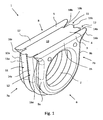
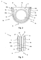
- Fig. 1 Fig. 2 and Fig. 3 is the sealing element 1 according to the invention according to a preferred embodiment shown in different views.
- the sealing element 1 which is made of an elastic plastic, serves to seal a cable inserted into a connection housing, as for example in FIG Fig. 4 is shown.
- the sealing element 1 is formed as a one-piece component and has a passage opening 2 for performing a in the Fig. 1-3 not shown on cable.
- the sealing element 1 is disc-shaped and, in the embodiment shown here, has three adjoining slices 3, 4, 5 which are connected to one another in a materially bonded manner and whose circumference is substantially U-shaped. Due to the U-shaped design of the discs 3, 4, 5, the entire sealing element 1 is formed in its shape substantially U-shaped.
- the first disc 3 and the third disc 5 are substantially the same in shape.
- the first disc 3 has, in the region of the side regions 7a, 7b of the sealing element 1, two opposite side flanks 9a, 9b, which run parallel to one another, so that their distance in the region of Side regions 7a, 7b substantially unchanged.
- the third disc 5 also has, in the region of the side regions 7a, 7b of the sealing element 1, two opposite side flanks 10a, 10b which run parallel to one another so that their spacing in the region of the side regions 7a, 7b does not substantially change.
- the second disc 4 is arranged between the first disc 3 and the third disc 5 and, in the embodiment shown here, has a first flank pair 11 and a second flank pair 12, which are arranged parallel to one another.
- the first flank pair 11 has two opposite side flanks 13a, 13b, which are conical to one another, ie that the distance between the opposite side flanks 13a, 13b increases from the underside 6 of the sealing element 1 towards the upper side 8 of the sealing element 1.
- the second flank pair 12 also has two opposite side flanks 14a, 14b, which are conical to one another.
- the side edges 13a, 13b, 14a, 14b of the second disc 4 Due to the conical design of the side flanks 13a, 13b, 14a, 14b of the second disc 4, the side edges 13a, 13b, 14a, 14b of the second disc 4 from the side edges 9a, 9b of the first disc 3 and the side edges 10a, 10b of the third disc 5 and form with respect to the side edges 9a, 9b of the first disc 3 and the side edges 10a, 10b, a rib-shaped bulge.
- the side edges 13a, 13b, 14a, 14b of the second disc 4 both on the side regions 7a, 7b and on the bottom 6 of the sealing member 1 of the side edges 9a, 9b of the first disc 3 and the side edges 10a, 10b of the third disc 5 and surmount them.
- the first disc 3 has a sealing lip 15, which is connected to the side flanks 9a, 9b of the first disc 3 in each case via a bevelled connecting region 16a, 16b.
- the sealing lip 15 has a greater length than the distance between the two side flanks 9a, 9b is formed, so that the two bevelled connecting portions 16a, 16b are tapered starting from the side edges 9a, 9b in the direction of the sealing lip 15, d. H. that the distance of the tapered connecting portions 16a, 16b towards the sealing lip 15 increases.
- the third disc 5 also has on the upper side 8 of the sealing element 1 a sealing lip 17 which is connected to the side flanks 10a, 10b of the third disc 5 in each case via a bevelled connecting region 18a, 18b.
- the sealing lip 17 has a greater length than the distance between the two side flanks 10a, 10b is formed, so that the two tapered connecting portions 18a, 18b are tapered starting from the side flanks 10a, 10b in the direction of the sealing lip 17, d. H. that the distance of the tapered connecting portions 18a, 18b towards the sealing lip 17 increases.
- the second disc 4 is flat or planar in the region of the upper side 8 of the sealing element. This flat surface 19 of the second disc 4 is adjacent to the sealing lip 15 of the first disc 3 and to the Seal lip 17 of the third disc 5, wherein the flat surface 19 of the second disc 4 is lower than the sealing lips 15, 17, which is particularly in Fig. 3 can be seen, so that the flat surface 19, which is formed between the two sealing lips 15, 17, is surmounted by the two sealing lips 15, 17.
- a housing bottom part 20 of a connection housing according to a possible embodiment of the invention is shown, in which a sealing element 1 as described above can be arranged.
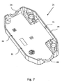
- an upper housing part 21 is shown, which can be connected to form the connection housing with the housing lower part 20.
- the connection housing has two cable insertion openings, which are each designed to be split, wherein in each case a first subregion 22 of the cable insertion opening is formed in the housing lower part 20 and a second subregion 23 in the housing upper part 21.
- a cable 24, 25 is inserted into the connection housing via the cable insertion openings.
- the lower housing part 20 has a substantially circumferential rib 26, which forms the boundary of an inner space 27 of the connection housing, in which a contacting of the individual conductors 24a - 24e, 25a - 25e of the cables 24, 25 takes place.
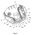
- the rib 26 may in this case be integrally formed on the housing lower part 20, made of the same material as the housing lower part 20. In the region of the cable insertion openings, the course of the rib 26 is interrupted, so that the rib 26 has a recess 28, as shown particularly in FIG Fig. 5 is shown.
- the sealing element 1 is arranged in the cable insertion opening such that the side edges 9a, 9b, 10a, 10b, 13a, 13b, 14a, 14b of the individual discs 3, 4, 5 of the sealing element 1 abut the rib 26.
- the rib 26 in each case adjacent to the recess 28 has a branch.
- the branch is in the form of a first rib arm 26a and a second rib arm 26b, wherein the first rib arm 26a abuts a side flank 9a, 9b of the first disc 3 and the second rib arm 26b abuts a side flank 10a, 10b of the third disc 5.
- the rib arms 26a, 26b span the recess 28 by means of one along the peripheral surface of the recess formed bulge 26c, on which the sealing element 1 with its bottom 6, in particular by the first disc 3 and the third disc 5 rest. Between the bulges 26c, a recess 26d is formed, in which the rib-shaped bulges of the two flank pairs 11, 12 of the second disc 4 rest.
- a potting material (not shown here) is produced injected into the limited by the rib 26 interior space 27 or poured so that the potting material distributed throughout the interior and this completely fills.
- the potting material is preferably a plastic injection molding material.
- the housing lower part 20 has a connection to the Cable insertion opening adjacent area a bulge 29, as shown in particular in Fig. 5 can be seen.
- the bulge 29 is preferably formed in the form of a recess or bulge in the housing base 20 and extends from the recess 28 of the rib 26 and the arrangement of the sealing element 1 in the recess 28 to the point in the interior 27 of the connection housing, from where the cable 24, 25 is stripped and the individual conductors 24a-24e, 25a-25e of the cable 24, 25 are exposed, as shown in FIG Fig. 4 is shown.
- flat sealing element 30 is placed on the housing lower part 20 such that the flat sealing element 30 rests on the rib 26 and at least partially on the sealing elements 1.
- the contour of the flat sealing element 30 is adapted by means of a stamping process to the shape of the rib 26 such that it completely covers the rib 26.
- the flat gasket 30 is preferably formed in the form of a thin rubber mat.
- the flat sealing element 30 is formed over the entire surface.
- the flat sealing element 30 it is also possible for the flat sealing element 30 to have a recess in the region of the inner space 27 of the lower housing part 20, so that the flat sealing element 30 does not completely overlap the inner space 27.
- an upper housing part 21, as shown in Fig. 7 is shown, placed on the housing base 20 and preferably by means of latching elements 31, which in formed on the rib 26 recesses 32, as shown in FIG Fig. 4 recognize, intervene, and additional Screws, not shown here, which are attached in the cable entry opening fixed.
- the flat gasket element 30 may be fastened on the inner surface of the upper housing part 21 pointing in the direction of the lower housing part 20, in particular adhesively bonded thereto by adhesive bonding. In the fastened or joined state, the edge 34 of the upper housing part 21 is on the outside of the rib 26, which points away from the interior 27 of the housing lower part, tight.
- Fig. 8 is a sectional view through a fully assembled connector housing shown, in which a provided with a sealing element 1 cable 24, 25 is disposed in a Jardineinfuelö réelle of the connection housing and between the lower housing part 20, or the rib 26 of the housing base 20, and the upper housing part 21, a flat sealing element 30 rests, which covers the top 8 of the sealing element 1.
- the flat sealing element 30 bears particularly tightly on the sealing lips 15, 17 of the first pane 3 and the third pane 5.
- a region of the rib 26 which adjoins the cable insertion opening has a bevelled edge region 33.
- the chamfered edge portion 33 is formed respectively at the free ends of the rib arms 26a, 26b, which adjoin the side edges 9a, 9b, 10a, 10b of the first disc 3 and the third disc 5. This facilitates the joining of the sealing element 1 into the recess 28 of the rib 26 in the region of the cable insertion opening.
- the terminal housing according to the invention can be preferably used or used as a so-called solar terminal housing for solar plug.
Landscapes
- Engineering & Computer Science (AREA)
- Architecture (AREA)
- Civil Engineering (AREA)
- Structural Engineering (AREA)
- Connector Housings Or Holding Contact Members (AREA)
- Cable Accessories (AREA)
- Connections Arranged To Contact A Plurality Of Conductors (AREA)
- Connection Or Junction Boxes (AREA)
Description
- Die Erfindung richtet sich auf ein Dichtungselement zur Abdichtung eines in ein Anschlussgehäuse eingeführten Kabels mit einer Durchführungsöffnung zur Durchführung des Kabels, wobei das Dichtungselement scheibenförmig mit mindestens einer ersten in ihrem Umfang im Wesentlichen U-förmig ausgebildeten Scheibe und einer zweiten in ihrem Umfang im Wesentlichen U-förmig ausgebildeten, an der ersten Scheibe anliegenden Scheibe ausgebildet ist, wobei die erste Scheibe zwei sich gegenüberliegende Seitenflanken aufweist, welche parallel zueinander verlaufen, und wobei die erste Scheibe an ihrer die beiden Seitenflanken der ersten Scheibe miteinander verbindenden Oberseite eine Dichtungslippe aufweist. Ferner richtet sich die Erfindung auf ein Anschlussgehäuse zum Verbinden von Leitern von zwei oder mehr Kabeln.
- Ein scheibenförmig ausgebildetes Dichtungselement nach dem Oberbegriff des Anspruchs 1 ist beispielsweise aus der
WO 97/02637 A1 - Um ein über eine Kabeleinführöffnung in ein Anschlussgehäuse eingeführtes Kabel abzudichten, ist es bekannt, ein im Wesentlichen ringförmig ausgebildetes Dichtungselement auf die Außenumfangsfläche des Kabels zu ziehen und das Kabel anschließend zusammen mit dem Dichtungselement in dem Gehäuse zu platzieren, wobei das Dichtungselement in der Kabeleinführöffnung des Anschlussgehäuses angeordnet wird, um den Innenraum des Anschlussgehäuses gegen Außeneinflüsse im Bereich der Einführöffnung des Kabels zu schützen. Zur weiteren Abdichtung kann der Innenraum des Anschlussgehäuses anschließend mit einer Dichtmasse bzw. einem Vergussmaterial ausgegossen oder ausgespritzt werden.
- Ist das Anschlussgehäuse aus einem Gehäuseunterteil und einem Gehäuseoberteil ausgebildet, ist es üblicherweise vorgesehen, einen ersten Teilbereich der Kabeleinführöffnung in dem Gehäuseunterteil und einen zweiten Teilbereich der Kabeleinführöffnung in dem Gehäuseoberteil auszubilden, wobei das Dichtungselement hierbei aus zwei Teilen ausgebildet ist und der erste Teil in dem Gehäuseunterteil und der zweite Teil in dem Gehäuseunterteil fest angeordnet ist, bevor das Kabel eingeführt wird. Zum Anschließen eines Kabels wird dann das Kabel in das Gehäuseunterteil auf den ersten Teil des Dichtungselements gelegt. Anschließend wird das Gehäuseoberteil auf dem Gehäuseunterteil befestigt, so dass auch der zweite Teil des Dichtungselements an dem Kabel anliegt.
- Beide mögliche Ausgestaltungen haben den Nachteil, dass eine sichere Abdichtung des Anschlussgehäuse und des darin angeschlossenen Kabels gegenüber von außen einwirkende Medien nicht gewährleistet werden kann.
- Die vorliegende Erfindung hat sich daher zur Aufgabe gemacht, ein verbessertes Dichtungselement und ein verbessertes Anschlussgehäuse zur Verfügung zu stellen, mit welchem die Dichtwirkung deutlich verbessert werden kann.
- Gemäß der Lehre der vorliegenden Erfindung wird die aufgezeigte Aufgabe bei einem Dichtungselement dadurch gelöst, dass die zweite Scheibe ein erstes Flankenpaar mit zwei sich gegenüberliegenden Seitenflanken aufweist, und dass die Dichtungslippe mit den Seitenflanken jeweils über einen abgeschrägten Verbindungsbereich verbunden ist.
- Das Dichtungselement gemäß der Erfindung zeichnet sich dadurch gegenüber den bisher bekannten einteilig ausgebildeten Dichtungselementen, welche auf die Außenumfangsfläche des Kabels gezogen werden, bevor das Kabel in ein Anschlussgehäuse eingelegt wird, aus, dass das Dichtungselement nunmehr aus mehreren nebeneinander liegenden Scheiben ausgebildet ist. Das Dichtungselement ist in seiner längsseitigen Querschnittsfläche im Wesentlichen U-förmig ausgebildet, wobei im Wesentlichen mittig der Längsseitenfläche des Dichtungselements eine, vorzugsweise kreisringförmige, Durchführungsöffnung zur Durchführung des anzuschließenden Kabels, ausgebildet ist. Über diese Durchführungsöffnung kann das Dichtungselement in Form einer Presspassung auf den Außenumfang des Kabels gezogen werden, so dass der Außenumfang des Kabels im Bereich des Dichtungselements vollständig von dem Dichtungselement umschlossen ist.
- Das Dichtungselement weist mindestens zwei Scheiben mit zwei sich jeweils gegenüberliegenden Seitenflanken auf, mit welchen das Dichtungselement im Bereich einer Kabeleinführungsöffnung eines Anschlussgehäuses an dem Anschlussgehäuse anliegt. Die beiden Seitenflanken der ersten Scheibe, mit welchen die erste Scheibe im Bereich der Kabeleinführöffnung an dem Anschlussgehäuse anliegt, verlaufen parallel zueinander. Die beiden Seitenflanken der zweiten Scheibe verlaufen hingegen konisch zueinander, so dass der Abstand der Seitenflanken der zweiten Scheibe hin zu der Oberseite des Dichtungselementes bzw. der Scheiben größer wird. Durch die konische Ausbildung der Seitenflanken der zweiten Scheibe stehen die Seitenflanken der zweiten Scheibe von den Seitenflanken der ersten Scheibe hervor und bilden gegenüber den Seitenflanken der ersten Scheibe eine rippenförmige Auswölbung aus, wodurch die Seitenflanken der zweiten Scheibe besonders dicht mittels einer Presspassung an dem Anschlussgehäuse anliegen. Vorzugsweise stehen die Seitenflanken der zweiten Scheibe sowohl an den Seitenbereichen als auch an der Unterseite des Dichtungselementes von den Seitenflanken der ersten Scheibe hervor und überragen diese. Im Bereich der Oberseite des Dichtungselementes hingegen überragt vorzugsweise die erste Scheibe die zweite Scheibe, indem die ersten Scheibe an ihrer die beiden Seitenflanken der ersten Scheibe miteinander verbindenden Oberseite eine Dichtungslippe aufweist, die mit den Seitenflanken jeweils über einen abgeschrägten Verbindungsbereich verbunden ist. Die Dichtungslippe ermöglicht eine besonders dichte Abdichtung zu dem Anschlussgehäuse im Bereich der Oberseite des Dichtungselementes. Die Dichtungslippe weist eine größere Breite auf als der Rest, insbesondere im Bereich der Seitenflanken, der ersten Scheibe, so dass insbesondere im Bereich der Oberseite des Dichtungselementes ein Spalt zwischen dem Dichtungselement und dem Anschlussgehäuse besonders wirkungsvoll verhindert werden kann. Der abgeschrägte Verbindungsbereich ist vorzugsweise konisch ausgebildet, wodurch eine über die Dichtungslippe auf das Dichtungselement wirkende Druckkraft durch eine Aufteilung der Druckkraft bei Einleitung in das Gehäuseunterteil besonders günstig in das Gehäuseunterteil eingeleitet.
- Gemäß einer bevorzugten Ausgestaltung der Erfindung weist das Dichtungselement eine dritte in ihrem Umfang im Wesentlichen U-förmig ausgebildete Scheibe mit einer entsprechend der ersten Scheibe ausgestalteten Form auf, wobei die dritte Scheibe derart angeordnet ist, dass die zweite Scheibe zwischen der ersten Scheibe und der dritten Scheibe angeordnet ist. Die dritte Scheibe weist somit ebenso wie die erste Scheibe zwei sich gegenüberliegende Seitenflanken auf, welche parallel zueinander verlaufen, und weist an ihrer die beiden Seitenflanken der dritten Scheibe miteinander verbindenden Oberseite eine Dichtungslippe, die mit den Seitenflanken jeweils über einen abgeschrägten Verbindungsbereich verbunden ist, auf. Die dritte Scheibe ist somit im Wesentlichen identisch zu der ersten Scheibe ausgebildet. Dadurch, dass die dritte Scheibe derart angeordnet ist, dass die zweite Scheibe zwischen der ersten Scheibe und der dritten Scheibe angeordnet ist, ist die zweite Scheibe von zwei im Wesentlichen baugleichen Scheiben eingerahmt. Das Dichtungselement weist dadurch eine Achssymmetrie auf, die es ermöglicht, das Dichtungselement über zwei Seiten in ein Anschlussgehäuse einzusetzen, was den Einbau des Dichtungselementes in einem Anschlussgehäuse erleichtert und Montagefehler verhindert.
- Um die Abdichtungswirkung der zweiten Scheibe zu erhöhen, welche vorzugsweise mittig in einem Dichtungselement angeordnet ist, ist es bevorzugt vorgesehen, dass die zweite Scheibe zusätzlich zu dem ersten Flankenpaar ein zweites Flankenpaar mit zwei sich gegenüberliegenden Seitenflanken aufweist, welche konisch zueinander ausgebildet sind. Das zweite Flankenpaar ist vorzugsweise entsprechend der Form des ersten Flankenpaares der zweiten Scheibe ausgebildet, so dass das zweite Flankenpaar ebenso wie das erste Flankenpaar eine im Bereich der Seitenbereiche und der Unterseite des Dichtungselementes ausgebildete rippenförmige Auswölbung bildet. Durch die zwei rippenförmigen Auswölbungen, welche parallel zueinander verlaufen, kann die Dichtwirkung der zweiten , Scheibe hin zu dem Anschlussgehäuse wesentlich verbessert werden.
- Vorzugsweise ist es ferner vorgesehen, dass die zweite Scheibe an ihrer die Seitenflanken miteinander verbindenden Oberseite eine eben ausgebildete Fläche aufweist. Die ebene Fläche grenzt an die Dichtungslippe der ersten Scheibe und der dritten Scheibe an, wobei die ebene Fläche tiefer liegt als die Dichtungslippen, so dass die ebene Fläche, welche zwischen den beiden Dichtungslippen ausgebildet ist, von den beiden Dichtungslippen überragt wird. Im Bereich der Oberseite des Dichtungselementes ist somit das Dichtungselement vorzugsweise in seiner Mitte flacher ausgebildet als an seinen Seitenkantenbereichen. Auch durch diese mögliche erfindungsgemäße Ausgestaltung des Dichtungselementes kann die Dichtwirkung des Dichtungselements weiter verbessert werden.
- Gemäß der Lehre der vorliegenden Erfindung wird die oben aufgezeigte Aufgabe für ein Anschlussgehäuse zum Verbinden von Leitern von zwei oder mehr Kabeln dadurch gelöst, dass das Anschlussgehäuse mindestens eine Kabeleinführöffnung, ein Gehäuseunterteil und ein Gehäuseoberteil aufweist, wobei ein erster Teilbereich der Kabeleinführöffnung in dem Gehäuseunterteil und ein zweiter Teilbereich der Kabeleinführöffnung in dem Gehäuseoberteil ausgebildet ist, wobei das Gehäuseunterteil eine im Wesentlichen umlaufende, einen Innenraum ausbildende Rippe aufweist, die im Bereich der Kabeleinführöffnung eine Aussparung aufweist, wobei in der Kabeleinführöffnung in der Aussparung der Rippe ein eine Durchführungsöffnung für ein anzuschließendes Kabel aufweisendes, einteilig ausgebildetes Dichtungselement angeordnet, welches nach einem der Ansprüche 1 bis 4 ausgebildet ist, wobei der durch die Rippe ausgebildete Innenraum mit einem Vergussmaterial gefüllt ist, und wobei im Bereich der Rippe zwischen dem Gehäuseunterteil und dem Gehäuseoberteil ein Flachdichtungselement angeordnet ist.
- Die Abdichtung des erfindungsgemäßen Anschlussgehäuses erfolgt somit im Gegensatz zu den bisher bekannten Anschlussgehäusen mittels einer an dem Gehäuseunterteil des Anschlussgehäuses ausgebildeten Rippe, einem im Bereich eines durch die Rippe ausgebildeten Innenraumes eingefüllten Vergussmaterials, insbesondere einer gummiartigen Kunststoffmasse, einem zwischen der Rippe des Gehäuseunterteils und dem Gehäuseoberteils angeordneten Flachdichtungselementes und einem im Bereich der Kabeleinführöffnung angeordneten, einteilig ausgebildeten Dichtungselementes. Durch die Kombination dieser verschiedenen Abdichtungselemente kann eine besonders wirkungsvolle Abdichtung des Anschlussgehäuses erreicht werden. Das Anschlussgehäuse ist hierbei zweiteilig, aus einem Gehäuseoberteil und einem Gehäuseunterteil ausgebildet. Das Dichtungselement im Bereich der Kabeleinführöffnung ist nicht bereits an dem Gehäuseunterteil und dem Gehäuseoberteil in Form einer zweiteiligen Ausbildung fest angeformt, sondern ist ein einteilig ausgebildetes, separates Bauteil, welches vor der Anordnung in dem Anschlussgehäuse zunächst mittels einer Presspassung über den Außenumfang des anzuschließenden Kabels gezogen wird und anschließend zusammen mit dem Kabel zunächst in die in dem Gehäuseunterteil ausgebildete Kabeleinführöffnung eingelegt wird. Hierdurch ist eine besonders sichere Abdichtung insbesondere im Bereich zwischen Kabel, Dichtungselement und Anschlussgehäuse möglich. Die Aufnahme des Dichtungselementes in dem Anschlussgehäuse im Bereich der Kabeleinführöffnung ist dabei derart gestaltet, dass das Dichtungselement sowohl axial zum Kabel als auch radial zum Kabel verpresst wird. Mittels des Flachdichtungselementes erfolgt eine sichere Abdichtung zum Gehäuseoberteil hin.
- Nach einer bevorzugten Ausgestaltung des Anschlussgehäuses ist das Flachdichtungselement derart ausgebildet, dass das Flachdichtungselement das Dichtungselement zumindest teilweise überlappt. Hierdurch ist ein direkter Kontakt zwischen dem Dichtungselement und dem Flachdichtungselement ermöglicht, wobei der Kontakt im Bereich der Oberseite des Dichtungselementes, welches an das Gehäuseoberteil angrenzt, erfolgt. Hierdurch ist eine besonders sichere Abdichtung des Kabels bzw. des Dichtungselementes zum Gehäuseoberteil hin möglich, was insbesondere bei zweiteilig ausgebildeten Anschlussgehäusen üblicherweise eine große Schwachstelle darstellt.
- Das in dem Anschlussgehäuse verwendete Dichtungselement ist besonders bevorzugt ein wie vorstehend aus- und weitergebildetes Dichtungselement, welches scheibenförmig mit mindestens einer ersten in ihrem Umgang im Wesentlichen U-förmig ausgebildeten Scheibe und einer zweiten in ihrem Umfang im Wesentlichen U-förmig ausgebildeten, an der ersten Scheibe anliegenden, Scheibe ausgebildet ist, wobei die erste Scheibe zwei sich gegenüberliegende Seitenflanken aufweist, welche parallel zueinander verlaufen, und die zweite Scheibe ein erstes Flankenpaar mit zwei sich gegenüberliegenden Seitenflanken aufweist, welche konisch zueinander ausgebildet sind, wobei die erste Scheibe an ihrer die beiden Seitenflanken der ersten Scheibe miteinander verbindenden Oberseite eine Dichtungslippe aufweist, die mit den Seitenflanken jeweils über einen abgeschrägten Verbindungsbereich verbunden ist. Das Dichtungselement kann dabei eine dritte in ihrem Umfang im Wesentlichen U-förmig ausgebildete Scheibe mit einer entsprechend der ersten Scheibe ausgestalteten Form aufweisen, wobei die dritte Scheibe derart angeordnet istm dass die zweite Scheibe zwischen der ersten Scheibe und der dritten Scheibe angeordnet ist. Ferner kann die zweite Scheibe ein zweites Flankenpaar mit zwei sich gegenüberliegenden Seitenflanken aufweisen, welche konisch zueinander ausgebildet sind. Weiter kann die zweite Scheibe an ihrer die Seitenflanken miteinander verbindenden Oberseite eine eben ausgebildete Oberfläche aufweisen. Ein derartig ausgebildetes Dichtungselement ermöglicht eine besonders sichere Abdichtung sowohl zum Kabel als auch zum Anschlussgehäuse hin, wodurch ein unerwünschtes Eindringen von Medien in das Anschlussgehäuse besonders wirkungsvoll verhindert werden kann.
- Um die Abdichtung zwischen dem Gehäuseoberteil und dem Gehäuseunterteil im Bereich der Kabeleinführöffnung besonders sicher ausgestalten zu können, ist es bevorzugt vorgesehen, dass ein Bereich der Rippe, welcher an die Kabeleinführöffnung angrenzt, einen abgeschrägten Kantenbereich aufweist. Der abgeschrägte Kantenbereich ist vorzugsweise an die Dichtungslippe bzw. den abgeschrägten Verbindungsbereich der ersten Scheibe des Dichtungselementes angepasst, so dass die Dichtungslippe passgenau im Bereich des abgeschrägten Kantenbereiches die Rippe überdeckt und damit die Kabeleinführöffnung zum Gehäuseoberteil hin überlappt und besonders wirkungsvoll abdichten kann.
- Ferner ist es vorzugsweise vorgesehen, dass die Rippe im Bereich der Kabeleinführöffnung eine Verzweigung aufweist, wodurch in dem kritischen Bereich, an dem das Gehäuseunterteil, das Gehäuseoberteil und das Dichtungselement aufeinandertreffen eine Redundanz erreicht wird. Die Verzweigung der Rippe ist vorzugsweise an beiden Enden der Rippe, wo die Rippe eine Aussparung aufweist und an die Kabeleinführöffnung angrenzt, ausgebildet, wobei die Verzweigung jeweils vorzugsweise in Form eines ersten Rippenarmes und eines zweiten Rippenarmes ausgebildet ist, wobei der erste Rippenarm an eine Seitenflanke der ersten Scheibe und der zweite Rippenarm an eine Seitenflanke der dritten Scheibe mittels einer Presspassung angrenzt, so dass in diesen Bereichen eine zusätzliche sichere Abdichtung erfolgen kann.
- Gemäß einer weiter bevorzugten Ausgestaltung des Anschlussgehäuses weist das Gehäuseunterteil an einem an die Kabeleinführöffnung angrenzenden Bereich eine Ausbuchtung auf. Die Ausbuchtung ist in dem Gehäuseunterteil unterhalb des angeschlossenen Kabels ausgebildet und ermöglicht, dass das in den Innenraum des Anschlussgehäuses eingebrachte Vergussmaterial sich auch ausreichend unterhalb des Kabels zwischen dem Kabel und dem Gehäuseunterteil ausbilden kann, um auch in diesem Bereich eine verbesserte Abdichtung zu erreichen.
- Es gibt nun eine Vielzahl von Möglichkeiten, das erfindungsgemäße Dichtungselement und das erfindungsgemäße Anschlussgehäuse auszugestalten und weiterzuentwickeln. Hierzu wird verwiesen einerseits auf die den Patentansprüchen 1 und 5 nachfolgenden Patentansprüche sowie auf die Beschreibung von Ausführungsbeispielen in Verbindung mit der Zeichnung. Die Zeichnung zeigt in
- Fig. 1
- eine schematische perspektivische Darstellung eines Dichtungselementes gemäß der Erfindung,
- Fig. 2
- eine schematische Darstellung des in
Fig. 1 gezeigten Dichtungselementes gemäß der Erfindung in einer Draufsicht auf eine Längsseite des Dichtungselementes, - Fig. 3
- eine schematische Darstellung des in
Fig. 1 gezeigten Dichtungselementes gemäß der Erfindung in einer Draufsicht auf eine Querseite des Dichtungselementes, - Fig. 4
- eine schematische Darstellung eines Gehäuseunterteils eines Anschlussgehäuses gemäß der Erfindung mit zwei in das Gehäuseunterteil eingeführten Kabeln und zwei im Bereich der Kabeleinführöffnungen des Gehäuseunterteils angeordneten Dichtungselementen, welche gemäß dem in
Fig. 1 gezeigten erfindungsgemäßen Dichtungselement ausgebildet ist, - Fig. 5
- eine schematische Detaildarstellung des in
Fig. 4 gezeigten Gehäuseunterteils gemäß der Erfindung, - Fig. 6
- eine schematische Darstellung eines Flachdichtungselementes gemäß der Erfindung in einer perspektivischen Ansicht,
- Fig. 7
- eine schematische Darstellung eines Gehäuseoberteils eines Anschlussgehäuses gemäß der Erfindung, und
- Fig. 8
- eine schematische Schnittdarstellung entlang der Querseite des Anschlussgehäuses gemäß der Erfindung im Bereich der Kabeleinführöffnung.
- In
Fig. 1 ,Fig. 2 und Fig. 3 wird das erfindungsgemäße Dichtungselement 1 gemäß einer bevorzugten Ausführungsform in verschiedenen Ansichten gezeigt. Das Dichtungselement 1, welches aus einem elastischen Kunststoff hergestellt ist, dient zur Abdichtung eines in ein Anschlussgehäuse eingeführten Kabels, wie es beispielsweise inFig. 4 gezeigt ist. Das Dichtungselement 1 ist als ein einteiliges Bauteil ausgebildet und weist eine Durchführungsöffnung 2 zur Durchführung eines in denFig. 1 - 3 nicht gezeigten Kabels auf. Das Dichtungselement 1 ist scheibenförmig ausgebildet und weist bei der hier gezeigten Ausführungsform drei aneinander angrenzende, stoffschlüssig miteinander verbundene, in ihrem Umfang im Wesentlichen U-förmig ausgebildete Scheiben 3, 4, 5 auf. Durch die U-förmige Ausbildung der Scheiben 3, 4, 5 ist das gesamte Dichtungselement 1 in seiner Form im Wesentlichen U-förmig ausgebildet. Dabei weist das Dichtungselement 1 eine Unterseite 6, zwei Seitenbereiche 7a, 7b und eine Oberseite 8 auf. Im Bereich der Unterseite 6 ist das Dichtungselement 1 und damit auch die Scheiben 3, 4, 5 im Wesentlichen halbkreisförmig ausgebildet. Im Bereich der Oberseite 8 ist das Dichtungselement 1 und damit auch die Scheiben 3, 4, 5 im Wesentlichen gerade ausgebildet. Die Form der Seitenbereiche 7a, 7b des Dichtungselementes 1 wird durch die einzelnen Scheiben 3, 4, 5 des Dichtungselementes bestimmt. Die Scheiben 3, 4, 5 selber sind im Bereich der Unterseite 6 und der Seitenbereiche 7a, 7b des Dichtungselementes 1 entlang ihrer Umrandung bzw. ihres Randbereiches abgerundet ausgebildet. - Die erste Scheibe 3 und die dritte Scheibe 5 sind im Wesentlichen in ihrer Form gleich ausgebildet. Die erste Scheibe 3 weist im Bereich der Seitenbereiche 7a, 7b des Dichtungselementes 1 zwei sich gegenüberliegende Seitenflanken 9a, 9b auf, welche parallel zueinander verlaufen, so dass sich deren Abstand im Bereich der Seitenbereiche 7a, 7b im Wesentlichen nicht verändert. Die dritte Scheibe 5 weist im Bereich der Seitenbereiche 7a, 7b des Dichtungselementes 1 ebenfalls zwei sich gegenüberliegende Seitenflanken 10a, 10b auf, welche parallel zueinander verlaufen, so dass sich deren Abstand im Bereich der Seitenbereiche 7a, 7b im Wesentlichen nicht verändert.
- Die zweite Scheibe 4 ist zwischen der ersten Scheibe 3 und der dritten Scheibe 5 angeordnet und weist bei der hier gezeigten Ausführungsform ein erstes Flankenpaar 11 und ein zweites Flankenpaar 12 auf, welche parallel zueinander angeordnet sind. Das erste Flankenpaar 11 weist zwei sich gegenüberliegende Seitenflanken 13a, 13b auf, welche konisch zueinander ausgebildet sind, d. h. dass sich der Abstand der gegenüberliegenden Seitenflanken 13a, 13b von der Unterseite 6 des Dichtungselementes 1 hin zu der Oberseite 8 des Dichtungselementes 1 vergrößert. Das zweite Flankenpaar 12 weist ebenfalls zwei sich gegenüberliegende Seitenflanken 14a, 14b auf, welche konisch zueinander ausgebildet sind. Durch die konische Ausbildung der Seitenflanken 13a, 13b, 14a, 14b der zweiten Scheibe 4 stehen die Seitenflanken 13a, 13b, 14a, 14b der zweiten Scheibe 4 von den Seitenflanken 9a, 9b der ersten Scheibe 3 und den Seitenflanken 10a, 10b der dritten Scheibe 5 hervor und bilden gegenüber den Seitenflanken 9a, 9b der ersten Scheibe 3 und der Seitenflanken 10a, 10b eine rippenförmige Auswölbung aus. Dabei stehen die Seitenflanken 13a, 13b, 14a, 14b der zweiten Scheibe 4 sowohl an den Seitenbereichen 7a, 7b als auch an der Unterseite 6 des Dichtungselements 1 von den Seitenflanken 9a, 9b der ersten Scheibe 3 und den Seitenflanken 10a, 10b der dritten Scheibe 5 hervor und überragen diese. Dadurch ist eine rippenförmige Auswölbung der Seitenflanken 13a, 13b, 14a, 14b der zweiten Scheibe 4 des Dichtungselementes über den gesamten Bereich der Seitenbereiche 7a, 7b und der Unterseite 6 des Dichtungselementes 1 ausgebildet.
- An der Oberseite 8 des Dichtungselementes 1 weist die erste Scheibe 3 eine Dichtungslippe 15 auf, die mit den Seitenflanken 9a, 9b der ersten Scheibe 3 jeweils über einen abgeschrägten Verbindungsbereich 16a, 16b verbunden ist. Die Dichtungslippe 15 weist eine größere Länge auf als der Abstand zwischen den beiden Seitenflanken 9a, 9b ausgebildet ist, so dass die beiden abgeschrägten Verbindungsbereiche 16a, 16b ausgehend von den Seitenflanken 9a, 9b in Richtung der Dichtungslippe 15 konisch ausgebildet sind, d. h. dass sich der Abstand der abgeschrägten Verbindungsbereiche 16a, 16b hin zu der Dichtungslippe 15 vergrößert.
- Die dritte Scheibe 5 weist ebenfalls an der Oberseite 8 des Dichtungselementes 1 eine Dichtungslippe 17 auf, die mit den Seitenflanken 10a, 10b der dritten Scheibe 5 jeweils über einen abgeschrägten Verbindungsbereich 18a, 18b verbunden ist. Die Dichtungslippe 17 weist eine größere Länge auf als der Abstand zwischen den beiden Seitenflanken 10a, 10b ausgebildet ist, so dass die beiden abgeschrägten Verbindungsbereiche 18a, 18b ausgehend von den Seitenflanken 10a, 10b in Richtung der Dichtungslippe 17 konisch ausgebildet sind, d. h. dass sich der Abstand der abgeschrägten Verbindungsbereiche 18a, 18b hin zu der Dichtungslippe 17 vergrößert.
- Die zweite Scheibe 4 ist im Bereich der Oberseite 8 des Dichtungselementes flach bzw. eben ausgebildet. Diese ebene Fläche 19 der zweiten Scheibe 4 grenzt an die Dichtungslippe 15 der ersten Scheibe 3 und an die Dichtungslippe 17 der dritten Scheibe 5 an, wobei die ebene Fläche 19 der zweiten Scheibe 4 tiefer liegt als die Dichtungslippen 15, 17, was insbesondere in
Fig. 3 zu erkennen ist, so dass die ebene Fläche 19, welche zwischen den beiden Dichtungslippen 15, 17 ausgebildet ist, von den beiden Dichtungslippen 15, 17 überragt wird. - In
Fig. 4 ist ein Gehäuseunterteil 20 eines Anschlussgehäuses gemäß einer möglichen Ausführungsform der Erfindung gezeigt, in welchem ein wie zuvor beschriebenes Dichtungselement 1 angeordnet werden kann. InFig. 7 ist ein Gehäuseoberteil 21 gezeigt, welches zur Ausbildung des Anschlussgehäuses mit dem Gehäuseunterteil 20 verbunden werden kann. Das Anschlussgehäuse weist bei der hier gezeigten Ausführungsform zwei Kabeleinführöffnungen auf, welche jeweils geteilt ausgebildet sind, wobei jeweils ein erster Teilbereich 22 der Kabeleinführöffnung in dem Gehäuseunterteil 20 und ein zweiter Teilbereich 23 in dem Gehäuseoberteil 21 ausgebildet ist. Über die Kabeleinführöffnungen ist jeweils ein Kabel 24, 25 in das Anschlussgehäuse eingeführt. - Das Gehäuseunterteil 20 weist eine im Wesentlichen umlaufende Rippe 26 auf, welche die Begrenzung eines Innenraumes 27 des Anschlussgehäuses ausbildet, in welchem eine Kontaktierung der einzelnen Leiter 24a - 24e, 25a - 25e der Kabel 24, 25 erfolgt. Die Rippe 26 kann hierbei einstückig an dem Gehäuseunterteil 20, aus dem gleichen Material wie das Gehäuseunterteil 20 ausgebildet sein. Im Bereich der Kabeleinführöffnungen ist der Verlauf der Rippe 26 unterbrochen, so dass die Rippe 26 eine Aussparung 28 aufweist, wie dies insbesondere in
Fig. 5 gezeigt ist. Das Dichtungselement 1 ist derart in der Kabeleinführöffnung angeordnet, dass die Seitenflanken 9a, 9b, 10a, 10b, 13a, 13b, 14a, 14b der einzelnen Scheiben 3, 4, 5 des Dichtungselementes 1 an der Rippe 26 anliegen. Im Bereich der zwei Kabeleinführöffnungen weist die Rippe 26 jeweils angrenzend zu der Aussparung 28 eine Verzweigung auf. Die Verzweigung ist jeweils in Form eines ersten Rippenarmes 26a und eines zweiten Rippenarmes 26b ausgebildet ist, wobei der erste Rippenarm 26a an eine Seitenflanke 9a, 9b der ersten Scheibe 3 und der zweite Rippenarm 26b an eine Seitenflanke 10a, 10b der dritten Scheibe 5 angrenzt. Wie inFig. 5 gezeigt ist, überspannen die Rippenarme 26a, 26b die Aussparung 28 mittels jeweils einer entlang der Umfangsfläche der Aussparung ausgebildeten Auswölbung 26c, auf welchen das Dichtungselement 1 mit seiner Unterseite 6, insbesondere der durch die erste Scheibe 3 und die dritte Scheibe 5 aufliegen. Zwischen den Auswölbungen 26c ist eine Vertiefung 26d ausgebildet, in welcher die rippenförmigen Auswölbungen der zwei Flankenpaare 11, 12 der zweiten Scheibe 4 aufliegen. - Nach dem Positionieren der Kabel 24, 25 mit den daran angeordneten Dichtungselementen 1 in dem Gehäuseunterteil 20 und dem Anschluss der Leiter 24a - 24e, 25a - 25e an in dem Anschlussgehäuse, insbesondere dem Gehäuseunterteil 20 des Anschlussgehäuses, ausgebildeten Kontakten wird ein hier nicht gezeigtes Vergussmaterial in den durch die Rippe 26 begrenzten Innenraum 27 eingespritzt oder eingegossen, so dass sich das Vergussmaterial in dem gesamten Innenraum verteilt und diesen vollständig ausfüllt. Das Vergussmaterial ist vorzugsweise ein Kunststoffspritzgussmaterial.
- Damit das Vergussmaterial auch das in das Anschlussgehäuse eingeführte Kabel 24, 25 vollständig umschließen kann, weist das Gehäuseunterteil 20 an einem an die Kabeleinführöffnung angrenzenden Bereich eine Ausbuchtung 29 auf, wie dies insbesondere in
Fig. 5 zu erkennen ist. Die Ausbuchtung 29 ist vorzugsweise in Form einer Vertiefung oder Auswölbung in dem Gehäuseunterteil 20 ausgebildet und erstreckt sich von der Aussparung 28 der Rippe 26 bzw. der Anordnung des Dichtungselementes 1 in der Aussparung 28 bis zu der Stelle in dem Innenraum 27 des Anschlussgehäuses, ab wo das Kabel 24, 25 abisoliert ist und die einzelnen Leiter 24a- 24e, 25a - 25e des Kabels 24, 25 frei liegen, wie dies inFig. 4 gezeigt ist. - Nach dem Einspritzen des Vergussmaterials in den Innenraum 27 wird ein wie in
Fig. 6 gezeigtes Flachdichtungselement 30 derart auf das Gehäuseunterteil 20 aufgelegt, dass das Flachdichtungselement 30 auf der Rippe 26 und zumindest teilweise auf den Dichtungselementen 1 aufliegt. Die Kontur des Flachdichtungselementes 30 ist dabei mittels eines Stanzprozesses an die Form der Rippe 26 derart angepasst, dass es die Rippe 26 vollständig überdeckt. Das Flachdichtungselement 30 ist vorzugsweise in Form einer dünnen Gummimatte ausgebildet. Bei der inFig. 6 gezeigten Ausführungsform ist das Flachdichtungselement 30 vollflächig ausgebildet. Es ist aber auch möglich, dass das Flachdichtungselement 30 im Bereich des Innenraumes 27 des Gehäuseunterteils 20 eine Aussparung aufweist, so dass das Flachdichtungselement 30 den Innenraum 27 nicht vollständig überlappt. - Zum Verschließen des Anschlussgehäuses wird zum Schluss ein Gehäuseoberteil 21, wie es in
Fig. 7 gezeigt ist, auf das Gehäuseunterteil 20 aufgesetzt und vorzugsweise mittels Verrastelementen 31, welche in an der Rippe 26 ausgebildeten Ausnehmungen 32, wie sie inFig. 4 zu erkennen sind, eingreifen können, und zusätzlichen Schrauben, hier nicht gezeigt, welche im Bereich der Kabeleinführöffnung befestigt werden, fixiert. Zur Vereinfachung der Montage, kann das Flachdichtungselement 30 auf der in Richtung Gehäuseunterteil 20 zeigenden Innenfläche des Gehäuseoberteils 21 befestigt, insbesondere durch eine Klebverbindung aufgeklebt, sein. Im befestigten bzw. zusammengefügten Zustand liegt der Rand 34 des Gehäuseoberteils 21 an der Außenseite der Rippe 26, welche von dem Innenraum 27 des Gehäuseunterteils weg zeigt, dicht an. - In
Fig. 8 ist eine Schnittdarstellung durch ein fertig montiertes Anschlussgehäuse gezeigt, bei welchem ein mit einem Dichtungselement 1 versehenes Kabel 24, 25 in einer Kabeleinführöffnung des Anschlussgehäuses angeordnet ist und zwischen dem Gehäuseunterteil 20, bzw. der Rippe 26 des Gehäuseunterteils 20, und dem Gehäuseoberteil 21 ein Flachdichtungselement 30 aufliegt, welches die Oberseite 8 des Dichtungselementes 1 überdeckt. Im Bereich des Dichtungselements 1 liegt das Flachdichtungselement 30 auf den Dichtungslippen 15, 17 der ersten Scheibe 3 und der dritten Scheibe 5 besonders dicht auf. Ferner ist hier zu erkennen, dass ein Bereich der Rippe 26, welcher an die Kabeleinführöffnung angrenzt, einen abgeschrägten Kantenbereich 33 aufweist. Wie insbesondere inFig. 5 zu erkennen ist, ist der abgeschrägte Kantenbereich 33 jeweils an den freien Enden der Rippenarme 26a, 26b, welche an die Seitenflanken 9a, 9b, 10a, 10b der ersten Scheibe 3 und der dritten Scheibe 5 angrenzen, ausgebildet. Hierdurch wird das Fügen des Dichtungselementes 1 in die Aussparung 28 der Rippe 26 im Bereich der Kabeleinführöffnung erleichtert. Das Anschlussgehäuse gemäß der Erfindung kann vorzugsweise als ein sogenanntes Solar-Anschlussgehäuse für Solarstecker eingesetzt bzw. verwendet werden. -
- Dichtungselement
- 1
- Durchführungsöffnung
- 2
- Erste Scheibe
- 3
- Zweite Scheibe
- 4
- Dritte Scheibe
- 5
- Unterseite
- 6
- Seitenbereich
- 7a, 7b
- Oberseite
- 8
- Seitenflanke
- 9a, 9b
- Seitenflanke
- 10a, 10b
- Erstes Flankenpaar
- 11
- Zweites Flankenpaar
- 12
- Seitenflanke
- 13a, 13b
- Seitenflanke
- 14a, 14b
- Dichtungslippe
- 15
- Abgeschrägter Verbindungsbereich
- 16a, 16b
- Dichtungslippe
- 17
- Abgeschrägter Verbindungsbereich
- 18a, 18b
- Ebene Fläche
- 19
- Gehäuseunterteil
- 20
- Gehäuseoberteil
- 21
- Erster Teilbereich der Kabeleinführöffnung
- 22
- Zweiter Teilbereich der Kabeleinführöffnung
- 23
- Kabel
- 24
- Leiter
- 24a - 24e
- Kabel
- 25
- Leiter
- 25a - 25e
- Rippe
- 26
- Rippenarm
- 26a, 26b
- Auswölbung
- 26c
- Vertiefung
- 26d
- Innenraum
- 27
- Aussparung
- 28
- Ausbuchtung
- 29
- Flachdichtungselement
- 30
- Verrastelement
- 31
- Ausnehmung
- 32
- Abgeschrägter Kantenbreich
- 33
- Rand
- 34
Claims (9)
- Dichtungselement (1) zur Abdichtung eines in ein Anschlussgehäuse eingeführten Kabels (24, 25), mit einer Durchführungsöffnung (2) zur Durchführung des Kabels (24, 25),
wobei das Dichtungselement (1) scheibenförmig mit mindestens einer ersten in ihrem Umfang im Wesentlichen U-förmig ausgebildeten Scheibe (3) und einer zweiten in ihrem Umfang im Wesentlichen U-förmig ausgebildeten, an der ersten Scheibe (3) anliegenden, Scheibe (4) ausgebildet ist,
wobei die erste Scheibe (3) zwei sich gegenüberliegende Seitenflanken (9a, 9b) aufweist, welche parallel zueinander verlaufen, und wobei die erste Scheibe (3) an ihrer die beiden Seitenflanken (9a, 9b) der ersten Scheibe (3) miteinander verbindenden Oberseite eine Dichtungslippe (15) aufweist,
dadurch gekennzeichnet, dass
die zweite Scheibe (4) ein erstes Flankenpaar (11) mit zwei sich gegenüberliegenden Seitenflanken (13a, 13b) aufweist, welche konisch zueinander ausgebildet sind, und dass die Dichtungslippe (15) mit den Seitenflanken (9a, 9b) jeweils über einen abgeschrägten Verbindungsbereich (16a, 16b) verbunden ist. - Dichtungselement (1) nach Anspruch 1, dadurch gekennzeichnet, dass das Dichtungselement (1) eine dritte in ihrem Umfang im Wesentlichen U-förmig ausgebildete Scheibe (5) mit einer entsprechend der ersten Scheibe (3) ausgestalteten Form aufweist, wobei die dritte Scheibe (5) derart angeordnet ist, dass die zweite Scheibe (4) zwischen der ersten Scheibe (3) und der dritten Scheibe (5) angeordnet ist.
- Dichtungselement (1) nach Anspruch 1 oder 2, dadurch gekennzeichnet, dass die zweite Scheibe (4) ein zweites Flankenpaar (12) mit zwei sich gegenüberliegenden Seitenflanken (14a, 14b) aufweist, welche konisch zueinander ausgebildet sind.
- Dichtungselement (1) nach einem der Ansprüche 1 bis 3, dadurch gekennzeichnet, dass die zweite Scheibe (4) an ihrer die Seitenflanken (14a, 14b) miteinander verbindenden Oberseite eine eben ausgebildete Fläche (19) aufweist.
- Anschlussgehäuse zum Verbinden von Leitern (24a - 24e, 25a - 25e) von zwei oder mehr Kabeln (24, 25),
mit mindestens einer Kabeleinführöffnung,
einem Gehäuseunterteil (20) und
einem Gehäuseoberteil (21),
wobei ein erster Teilbereich (22) der Kabeleinführöffnung in dem Gehäuseunterteil (20) und ein zweiter Teilbereich (23) der Kabeleinführöffnung in dem Gehäuseoberteil (21) ausgebildet ist,
wobei das Gehäuseunterteil (20) eine im Wesentlichen umlaufende, einen Innenraum (27) ausbildende Rippe (26) aufweist, die im Bereich der Kabeleinführöffnung eine Aussparung (28) aufweist,
wobei in der Kabeleinführöffnung in der Aussparung (28) der Rippe (26) ein eine Durchführungsöffnung (2) für ein anzuschließendes Kabel (24, 25) aufweisendes, einteilig ausgebildetes Dichtungselement (1) angeordnet ist, welches nach einem der Ansprüche 1 bis 4 ausgebildet ist,
wobei der durch die Rippe (26) ausgebildete Innenraum (27) mit einem Vergussmaterial gefüllt ist, und
wobei im Bereich der Rippe (26) zwischen dem Gehäuseunterteil (20) und dem Gehäuseoberteil (21) ein Flachdichtungselement (30) angeordnet ist. - Anschlussgehäuse nach Anspruch 5, dadurch gekennzeichnet, dass das Flachdichtungselement (30) das Dichtungselement (1) zumindest teilweise überlappt.
- Anschlussgehäuse nach Anspruch 5 oder 6, dadurch gekennzeichnet, dass ein Bereich der Rippe (26), welcher an die Kabeleinführöffnung angrenzt, einen abgeschrägten Kantenbereich (33) aufweist.
- Anschlussgehäuse nach einem der Ansprüche 5 bis 7, dadurch gekennzeichnet, dass die Rippe (26) im Bereich der Kabeleinführöffnung eine Verzweigung aufweist.
- Anschlussgehäuse nach einem der Ansprüche 5 bis 8, dadurch gekennzeichnet, dass das Gehäuseunterteil (20) an einem an die Kabeleinführöffnung angrenzenden Bereich eine Ausbuchtung (29) aufweist.
Applications Claiming Priority (2)
| Application Number | Priority Date | Filing Date | Title |
|---|---|---|---|
| DE102011103351A DE102011103351B3 (de) | 2011-05-27 | 2011-05-27 | Dichtungselement und Anschlussgehäuse mit einem Dichtungselement |
| PCT/EP2012/002247 WO2012163507A2 (de) | 2011-05-27 | 2012-05-25 | Dichtungselement und anschlussgehäuse mit einem dichtungselement |
Publications (2)
| Publication Number | Publication Date |
|---|---|
| EP2715895A2 EP2715895A2 (de) | 2014-04-09 |
| EP2715895B1 true EP2715895B1 (de) | 2015-08-19 |
Family
ID=46456480
Family Applications (1)
| Application Number | Title | Priority Date | Filing Date |
|---|---|---|---|
| EP12731297.3A Not-in-force EP2715895B1 (de) | 2011-05-27 | 2012-05-25 | Dichtungselement und anschlussgehäuse mit einem dichtungselement |
Country Status (5)
| Country | Link |
|---|---|
| US (1) | US9136686B2 (de) |
| EP (1) | EP2715895B1 (de) |
| CN (1) | CN103582986B (de) |
| DE (1) | DE102011103351B3 (de) |
| WO (1) | WO2012163507A2 (de) |
Families Citing this family (19)
| Publication number | Priority date | Publication date | Assignee | Title |
|---|---|---|---|---|
| US8315040B2 (en) * | 2007-10-16 | 2012-11-20 | Traxxas Lp | Protective enclosure for model vehicle |
| RU2015100264A (ru) | 2012-07-02 | 2016-08-20 | Тайко Электроникс Рейкем Бвба | Рентерабельный кожух |
| ITRE20130007A1 (it) * | 2013-02-12 | 2014-08-13 | Conchiglia Societa Per Azioni | Sistema di derivazione per cavi elettrici indivisi |
| DE102013004189B4 (de) * | 2013-03-12 | 2019-07-18 | Sew-Eurodrive Gmbh & Co Kg | Elektrogerät mit Gehäuse und auf dem Gehäuse aufsetzbarem Deckel |
| DE102013210532A1 (de) * | 2013-06-06 | 2014-12-11 | Siemens Aktiengesellschaft | Kabelanschlusskasten |
| US9425604B1 (en) * | 2013-12-13 | 2016-08-23 | James Brooks Lawrence | Adjustable electrical cord connector protection device |
| US9291786B2 (en) * | 2013-12-31 | 2016-03-22 | All Systems Broadband, Inc. | Grommet for fiber optic enclosures |
| EP3342006B1 (de) * | 2015-08-27 | 2022-08-03 | Phoenix Contact GmbH & Co. KG | Elektrische kabelbaugruppe |
| CN106876226A (zh) * | 2015-12-14 | 2017-06-20 | 比亚迪股份有限公司 | 防水保险盒及具有其的车辆 |
| DE102016114577A1 (de) * | 2016-08-05 | 2018-02-08 | Harting Electric Gmbh & Co. Kg | Vorrichtung und Verfahren zur Kabeldurchführung durch einen Wanddurchbruch |
| DE102017129923A1 (de) * | 2017-11-24 | 2019-05-29 | Harting Electric Gmbh & Co. Kg | Kabeldurchführung |
| DE102018104915A1 (de) * | 2018-03-05 | 2019-09-05 | Te Connectivity Germany Gmbh | Dichtungseinrichtung für eine Leitung sowie elektrischer Verbinder |
| JP6924387B2 (ja) * | 2018-03-15 | 2021-08-25 | 株式会社オートネットワーク技術研究所 | 電線の保持構造 |
| CN108695799B (zh) * | 2018-08-13 | 2023-08-25 | 珠海格力电器股份有限公司 | 过线结构、电器盒及空调器 |
| WO2021230938A1 (en) | 2020-05-13 | 2021-11-18 | GAF Energy LLC | Electrical cable passthrough |
| CN112018716B (zh) * | 2020-09-21 | 2021-12-28 | 安徽伊法拉电气股份有限公司 | 一种柔性电缆中间快速接头的绝缘防护装置 |
| CN115968155A (zh) * | 2021-10-13 | 2023-04-14 | 台达电子工业股份有限公司 | 电子装置防水结构 |
| DE102023202054A1 (de) * | 2023-03-08 | 2024-09-12 | Zf Friedrichshafen Ag | Verbindungsanordnung zwischen zwei Gehäusekammern eines Steuergeräts |
| CN223514306U (zh) * | 2024-11-19 | 2025-11-04 | 苏州钛尔拉科技有限公司 | 一种充电桩接口密封装置 |
Family Cites Families (15)
| Publication number | Priority date | Publication date | Assignee | Title |
|---|---|---|---|---|
| US5313546A (en) | 1991-11-29 | 1994-05-17 | Sirti, S.P.A. | Hermetically sealed joint cover for fibre optic cables |
| DE4207281C1 (de) * | 1992-03-07 | 1993-04-29 | Rittal-Werk Rudolf Loh Gmbh & Co Kg, 6348 Herborn, De | |
| DE4300521A1 (de) * | 1993-01-12 | 1994-07-14 | Weidmueller Interface | Kabelabdichtungs- und Zugentlastungsvorrichtung für Wanddurchbrüche |
| JP3010411B2 (ja) * | 1994-03-18 | 2000-02-21 | 矢崎総業株式会社 | 防水ゴム栓および防水コネクタ |
| EP0835544B1 (de) | 1995-06-30 | 2000-08-30 | N.V. Raychem S.A. | Kabelabdichtungseinsatz |
| DE19701511C2 (de) * | 1996-01-18 | 2000-10-26 | Draexlmaier Lisa Gmbh | Tülle zur Durchführung von elektrischen Leitungen durch Wandungen, insbesondere in Kraftfahrzeugen |
| JP2002117930A (ja) * | 2000-10-06 | 2002-04-19 | Tyco Electronics Amp Kk | 防水グロメット |
| JP3914399B2 (ja) * | 2001-06-12 | 2007-05-16 | 矢崎総業株式会社 | 電気接続箱の防水構造 |
| JP4114599B2 (ja) | 2003-12-01 | 2008-07-09 | 住友電装株式会社 | グロメットの取付構造 |
| US7186929B2 (en) * | 2005-07-08 | 2007-03-06 | 3M Innovative Properties Company | Sealing member for an entry port |
| FI119040B (fi) * | 2006-05-15 | 2008-06-30 | Ensto Control Oy | Läpiviennillinen kotelo ja läpivientitiiviste |
| FR2940534B1 (fr) | 2008-12-18 | 2013-01-25 | Leoni Wiring Systems France | Joint d'etancheite monofilaire a grande longevite. |
| DE202010005085U1 (de) * | 2010-04-15 | 2010-11-18 | Phoenix Contact Gmbh & Co. Kg | Leadframe und Anschlussdose mit einem Leadframe |
| WO2012074685A2 (en) * | 2010-11-29 | 2012-06-07 | 3M Innovative Properties Company | Strain relief device |
| JP5720362B2 (ja) * | 2011-03-28 | 2015-05-20 | 住友電装株式会社 | 仕切り付きシールドパイプ |
-
2011
- 2011-05-27 DE DE102011103351A patent/DE102011103351B3/de not_active Expired - Fee Related
-
2012
- 2012-05-25 US US14/122,249 patent/US9136686B2/en not_active Expired - Fee Related
- 2012-05-25 CN CN201280025919.5A patent/CN103582986B/zh not_active Expired - Fee Related
- 2012-05-25 EP EP12731297.3A patent/EP2715895B1/de not_active Not-in-force
- 2012-05-25 WO PCT/EP2012/002247 patent/WO2012163507A2/de not_active Ceased
Also Published As
| Publication number | Publication date |
|---|---|
| CN103582986A (zh) | 2014-02-12 |
| EP2715895A2 (de) | 2014-04-09 |
| WO2012163507A3 (de) | 2013-06-06 |
| DE102011103351B3 (de) | 2012-09-13 |
| WO2012163507A2 (de) | 2012-12-06 |
| US20140182928A1 (en) | 2014-07-03 |
| CN103582986B (zh) | 2017-02-22 |
| US9136686B2 (en) | 2015-09-15 |
Similar Documents
| Publication | Publication Date | Title |
|---|---|---|
| DE102011103351B3 (de) | Dichtungselement und Anschlussgehäuse mit einem Dichtungselement | |
| DE102017121459B4 (de) | Kabelabdichtung sowie Anordnung mit einem Gehäuse | |
| EP1516394B1 (de) | Kontakteinrichtung zur elektrischen kontaktierung von kabelschirmungen | |
| DE102020208149A1 (de) | Modulverbinder | |
| EP2979329B1 (de) | Fluiddichte kontaktdurchführung | |
| EP3622588B1 (de) | Verfahren zur montage eines steckers an einer mehradrigen mantelleitung sowie elektrischer stecker | |
| WO2020221537A1 (de) | Befestigungsanordnung mit dämpfungswirkung und bauteilverbindung mit der befestigungsanordnung | |
| EP3488128B1 (de) | Dichtungselement zur fluiddichten und elektrisch leitenden verbindung eines ersten bauteils und eines zweiten bauteils sowie entsprechende bauteilanordnung | |
| DE2440648A1 (de) | Elektrische steckverbindung | |
| DE112015001734T5 (de) | Elektromagnetisches Schirmelement | |
| EP1936750B1 (de) | Flachleiter-Dichtelement | |
| WO2016082822A1 (de) | Steckverbinder für flexible leiterfolien | |
| EP1796216B1 (de) | Kabelschuh | |
| EP2771949B1 (de) | Steckverbindung mit einer schirmkontaktfeder | |
| EP2337161B1 (de) | Steckeranordnung und Abdichteinrichtung für wenigstens eine, insbesondere elektrische Leitung | |
| DE102022109354A1 (de) | Dichtung für doppelschienen-leiteranordnung | |
| DE10021672B4 (de) | Hermetisch verkapselter Sensor und Verfahren zu seiner Herstellung | |
| EP1870909A1 (de) | Flachbandkabel | |
| EP2076946A1 (de) | Plankommutator | |
| EP2884598B1 (de) | Stecker für ein Datenkabel und Verfahren zu dessen Herstellung | |
| EP0987483A1 (de) | Elektrisch leitende Rohr- oder Kabelschelle | |
| DE112018005718T5 (de) | Verbinder | |
| EP3503307A1 (de) | Elektrisches kupplungsteil und dichtelement | |
| DE2525221A1 (de) | Elektrische reihenverbindungsanordnung | |
| EP3800749B1 (de) | Verfahren zur herstellung eines elektrisch leitenden kontaktelements, elektrisch leitendes kontaktelement und hülse mit einem elektrisch leitenden kontaktelement |
Legal Events
| Date | Code | Title | Description |
|---|---|---|---|
| PUAI | Public reference made under article 153(3) epc to a published international application that has entered the european phase |
Free format text: ORIGINAL CODE: 0009012 |
|
| 17P | Request for examination filed |
Effective date: 20131210 |
|
| AK | Designated contracting states |
Kind code of ref document: A2 Designated state(s): AL AT BE BG CH CY CZ DE DK EE ES FI FR GB GR HR HU IE IS IT LI LT LU LV MC MK MT NL NO PL PT RO RS SE SI SK SM TR |
|
| DAX | Request for extension of the european patent (deleted) | ||
| GRAP | Despatch of communication of intention to grant a patent |
Free format text: ORIGINAL CODE: EPIDOSNIGR1 |
|
| INTG | Intention to grant announced |
Effective date: 20150407 |
|
| RIN1 | Information on inventor provided before grant (corrected) |
Inventor name: ENGEL ANSGAR Inventor name: STARKE, CORD Inventor name: SCHAEFER, SEBASTIAN Inventor name: SCHOLZ SEBASTIAN Inventor name: REIMCHEN, VALERI Inventor name: LEINECKE GERD |
|
| GRAS | Grant fee paid |
Free format text: ORIGINAL CODE: EPIDOSNIGR3 |
|
| GRAA | (expected) grant |
Free format text: ORIGINAL CODE: 0009210 |
|
| RIN1 | Information on inventor provided before grant (corrected) |
Inventor name: ENGEL ANSGAR Inventor name: LEINECKE GERD Inventor name: SCHAEFER, SEBASTIAN Inventor name: STARKE, CORD Inventor name: REIMCHEN, VALERI Inventor name: SCHOLZ SEBASTIAN |
|
| AK | Designated contracting states |
Kind code of ref document: B1 Designated state(s): AL AT BE BG CH CY CZ DE DK EE ES FI FR GB GR HR HU IE IS IT LI LT LU LV MC MK MT NL NO PL PT RO RS SE SI SK SM TR |
|
| REG | Reference to a national code |
Ref country code: GB Ref legal event code: FG4D Free format text: NOT ENGLISH |
|
| REG | Reference to a national code |
Ref country code: CH Ref legal event code: EP |
|
| REG | Reference to a national code |
Ref country code: IE Ref legal event code: FG4D Free format text: LANGUAGE OF EP DOCUMENT: GERMAN |
|
| REG | Reference to a national code |
Ref country code: AT Ref legal event code: REF Ref document number: 744390 Country of ref document: AT Kind code of ref document: T Effective date: 20150915 |
|
| REG | Reference to a national code |
Ref country code: DE Ref legal event code: R096 Ref document number: 502012004235 Country of ref document: DE |
|
| REG | Reference to a national code |
Ref country code: LT Ref legal event code: MG4D |
|
| REG | Reference to a national code |
Ref country code: NL Ref legal event code: MP Effective date: 20150819 |
|
| PG25 | Lapsed in a contracting state [announced via postgrant information from national office to epo] |
Ref country code: FI Free format text: LAPSE BECAUSE OF FAILURE TO SUBMIT A TRANSLATION OF THE DESCRIPTION OR TO PAY THE FEE WITHIN THE PRESCRIBED TIME-LIMIT Effective date: 20150819 Ref country code: NO Free format text: LAPSE BECAUSE OF FAILURE TO SUBMIT A TRANSLATION OF THE DESCRIPTION OR TO PAY THE FEE WITHIN THE PRESCRIBED TIME-LIMIT Effective date: 20151119 Ref country code: LT Free format text: LAPSE BECAUSE OF FAILURE TO SUBMIT A TRANSLATION OF THE DESCRIPTION OR TO PAY THE FEE WITHIN THE PRESCRIBED TIME-LIMIT Effective date: 20150819 Ref country code: LV Free format text: LAPSE BECAUSE OF FAILURE TO SUBMIT A TRANSLATION OF THE DESCRIPTION OR TO PAY THE FEE WITHIN THE PRESCRIBED TIME-LIMIT Effective date: 20150819 Ref country code: GR Free format text: LAPSE BECAUSE OF FAILURE TO SUBMIT A TRANSLATION OF THE DESCRIPTION OR TO PAY THE FEE WITHIN THE PRESCRIBED TIME-LIMIT Effective date: 20151120 |
|
| PG25 | Lapsed in a contracting state [announced via postgrant information from national office to epo] |
Ref country code: PT Free format text: LAPSE BECAUSE OF FAILURE TO SUBMIT A TRANSLATION OF THE DESCRIPTION OR TO PAY THE FEE WITHIN THE PRESCRIBED TIME-LIMIT Effective date: 20151221 Ref country code: RS Free format text: LAPSE BECAUSE OF FAILURE TO SUBMIT A TRANSLATION OF THE DESCRIPTION OR TO PAY THE FEE WITHIN THE PRESCRIBED TIME-LIMIT Effective date: 20150819 Ref country code: PL Free format text: LAPSE BECAUSE OF FAILURE TO SUBMIT A TRANSLATION OF THE DESCRIPTION OR TO PAY THE FEE WITHIN THE PRESCRIBED TIME-LIMIT Effective date: 20150819 Ref country code: IS Free format text: LAPSE BECAUSE OF FAILURE TO SUBMIT A TRANSLATION OF THE DESCRIPTION OR TO PAY THE FEE WITHIN THE PRESCRIBED TIME-LIMIT Effective date: 20151219 Ref country code: ES Free format text: LAPSE BECAUSE OF FAILURE TO SUBMIT A TRANSLATION OF THE DESCRIPTION OR TO PAY THE FEE WITHIN THE PRESCRIBED TIME-LIMIT Effective date: 20150819 Ref country code: SE Free format text: LAPSE BECAUSE OF FAILURE TO SUBMIT A TRANSLATION OF THE DESCRIPTION OR TO PAY THE FEE WITHIN THE PRESCRIBED TIME-LIMIT Effective date: 20150819 |
|
| PG25 | Lapsed in a contracting state [announced via postgrant information from national office to epo] |
Ref country code: NL Free format text: LAPSE BECAUSE OF FAILURE TO SUBMIT A TRANSLATION OF THE DESCRIPTION OR TO PAY THE FEE WITHIN THE PRESCRIBED TIME-LIMIT Effective date: 20150819 |
|
| PG25 | Lapsed in a contracting state [announced via postgrant information from national office to epo] |
Ref country code: EE Free format text: LAPSE BECAUSE OF FAILURE TO SUBMIT A TRANSLATION OF THE DESCRIPTION OR TO PAY THE FEE WITHIN THE PRESCRIBED TIME-LIMIT Effective date: 20150819 Ref country code: CZ Free format text: LAPSE BECAUSE OF FAILURE TO SUBMIT A TRANSLATION OF THE DESCRIPTION OR TO PAY THE FEE WITHIN THE PRESCRIBED TIME-LIMIT Effective date: 20150819 Ref country code: DK Free format text: LAPSE BECAUSE OF FAILURE TO SUBMIT A TRANSLATION OF THE DESCRIPTION OR TO PAY THE FEE WITHIN THE PRESCRIBED TIME-LIMIT Effective date: 20150819 Ref country code: SK Free format text: LAPSE BECAUSE OF FAILURE TO SUBMIT A TRANSLATION OF THE DESCRIPTION OR TO PAY THE FEE WITHIN THE PRESCRIBED TIME-LIMIT Effective date: 20150819 |
|
| REG | Reference to a national code |
Ref country code: FR Ref legal event code: PLFP Year of fee payment: 5 |
|
| REG | Reference to a national code |
Ref country code: DE Ref legal event code: R097 Ref document number: 502012004235 Country of ref document: DE |
|
| PG25 | Lapsed in a contracting state [announced via postgrant information from national office to epo] |
Ref country code: RO Free format text: LAPSE BECAUSE OF FAILURE TO SUBMIT A TRANSLATION OF THE DESCRIPTION OR TO PAY THE FEE WITHIN THE PRESCRIBED TIME-LIMIT Effective date: 20150819 |
|
| PLBE | No opposition filed within time limit |
Free format text: ORIGINAL CODE: 0009261 |
|
| STAA | Information on the status of an ep patent application or granted ep patent |
Free format text: STATUS: NO OPPOSITION FILED WITHIN TIME LIMIT |
|
| 26N | No opposition filed |
Effective date: 20160520 |
|
| PG25 | Lapsed in a contracting state [announced via postgrant information from national office to epo] |
Ref country code: BE Free format text: LAPSE BECAUSE OF NON-PAYMENT OF DUE FEES Effective date: 20160531 Ref country code: SI Free format text: LAPSE BECAUSE OF FAILURE TO SUBMIT A TRANSLATION OF THE DESCRIPTION OR TO PAY THE FEE WITHIN THE PRESCRIBED TIME-LIMIT Effective date: 20150819 |
|
| PG25 | Lapsed in a contracting state [announced via postgrant information from national office to epo] |
Ref country code: LU Free format text: LAPSE BECAUSE OF FAILURE TO SUBMIT A TRANSLATION OF THE DESCRIPTION OR TO PAY THE FEE WITHIN THE PRESCRIBED TIME-LIMIT Effective date: 20160525 |
|
| REG | Reference to a national code |
Ref country code: CH Ref legal event code: PL |
|
| GBPC | Gb: european patent ceased through non-payment of renewal fee |
Effective date: 20160525 |
|
| PG25 | Lapsed in a contracting state [announced via postgrant information from national office to epo] |
Ref country code: LI Free format text: LAPSE BECAUSE OF NON-PAYMENT OF DUE FEES Effective date: 20160531 Ref country code: CH Free format text: LAPSE BECAUSE OF NON-PAYMENT OF DUE FEES Effective date: 20160531 |
|
| REG | Reference to a national code |
Ref country code: IE Ref legal event code: MM4A |
|
| REG | Reference to a national code |
Ref country code: FR Ref legal event code: PLFP Year of fee payment: 6 |
|
| PG25 | Lapsed in a contracting state [announced via postgrant information from national office to epo] |
Ref country code: GB Free format text: LAPSE BECAUSE OF NON-PAYMENT OF DUE FEES Effective date: 20160525 Ref country code: IE Free format text: LAPSE BECAUSE OF NON-PAYMENT OF DUE FEES Effective date: 20160525 |
|
| REG | Reference to a national code |
Ref country code: FR Ref legal event code: PLFP Year of fee payment: 7 |
|
| PG25 | Lapsed in a contracting state [announced via postgrant information from national office to epo] |
Ref country code: SM Free format text: LAPSE BECAUSE OF FAILURE TO SUBMIT A TRANSLATION OF THE DESCRIPTION OR TO PAY THE FEE WITHIN THE PRESCRIBED TIME-LIMIT Effective date: 20150819 Ref country code: HU Free format text: LAPSE BECAUSE OF FAILURE TO SUBMIT A TRANSLATION OF THE DESCRIPTION OR TO PAY THE FEE WITHIN THE PRESCRIBED TIME-LIMIT; INVALID AB INITIO Effective date: 20120525 Ref country code: CY Free format text: LAPSE BECAUSE OF FAILURE TO SUBMIT A TRANSLATION OF THE DESCRIPTION OR TO PAY THE FEE WITHIN THE PRESCRIBED TIME-LIMIT Effective date: 20150819 |
|
| PG25 | Lapsed in a contracting state [announced via postgrant information from national office to epo] |
Ref country code: MT Free format text: LAPSE BECAUSE OF FAILURE TO SUBMIT A TRANSLATION OF THE DESCRIPTION OR TO PAY THE FEE WITHIN THE PRESCRIBED TIME-LIMIT Effective date: 20150819 Ref country code: TR Free format text: LAPSE BECAUSE OF FAILURE TO SUBMIT A TRANSLATION OF THE DESCRIPTION OR TO PAY THE FEE WITHIN THE PRESCRIBED TIME-LIMIT Effective date: 20150819 Ref country code: MC Free format text: LAPSE BECAUSE OF FAILURE TO SUBMIT A TRANSLATION OF THE DESCRIPTION OR TO PAY THE FEE WITHIN THE PRESCRIBED TIME-LIMIT Effective date: 20150819 Ref country code: HR Free format text: LAPSE BECAUSE OF FAILURE TO SUBMIT A TRANSLATION OF THE DESCRIPTION OR TO PAY THE FEE WITHIN THE PRESCRIBED TIME-LIMIT Effective date: 20150819 Ref country code: MK Free format text: LAPSE BECAUSE OF FAILURE TO SUBMIT A TRANSLATION OF THE DESCRIPTION OR TO PAY THE FEE WITHIN THE PRESCRIBED TIME-LIMIT Effective date: 20150819 |
|
| REG | Reference to a national code |
Ref country code: AT Ref legal event code: MM01 Ref document number: 744390 Country of ref document: AT Kind code of ref document: T Effective date: 20170525 |
|
| PG25 | Lapsed in a contracting state [announced via postgrant information from national office to epo] |
Ref country code: BG Free format text: LAPSE BECAUSE OF FAILURE TO SUBMIT A TRANSLATION OF THE DESCRIPTION OR TO PAY THE FEE WITHIN THE PRESCRIBED TIME-LIMIT Effective date: 20150819 |
|
| PG25 | Lapsed in a contracting state [announced via postgrant information from national office to epo] |
Ref country code: AT Free format text: LAPSE BECAUSE OF NON-PAYMENT OF DUE FEES Effective date: 20170525 |
|
| PG25 | Lapsed in a contracting state [announced via postgrant information from national office to epo] |
Ref country code: AL Free format text: LAPSE BECAUSE OF FAILURE TO SUBMIT A TRANSLATION OF THE DESCRIPTION OR TO PAY THE FEE WITHIN THE PRESCRIBED TIME-LIMIT Effective date: 20150819 |
|
| PGFP | Annual fee paid to national office [announced via postgrant information from national office to epo] |
Ref country code: FR Payment date: 20200528 Year of fee payment: 9 |
|
| PGFP | Annual fee paid to national office [announced via postgrant information from national office to epo] |
Ref country code: IT Payment date: 20200522 Year of fee payment: 9 |
|
| PG25 | Lapsed in a contracting state [announced via postgrant information from national office to epo] |
Ref country code: FR Free format text: LAPSE BECAUSE OF NON-PAYMENT OF DUE FEES Effective date: 20210531 |
|
| PG25 | Lapsed in a contracting state [announced via postgrant information from national office to epo] |
Ref country code: IT Free format text: LAPSE BECAUSE OF NON-PAYMENT OF DUE FEES Effective date: 20200525 |
|
| P01 | Opt-out of the competence of the unified patent court (upc) registered |
Effective date: 20230424 |
|
| PGFP | Annual fee paid to national office [announced via postgrant information from national office to epo] |
Ref country code: DE Payment date: 20230726 Year of fee payment: 12 |
|
| REG | Reference to a national code |
Ref country code: DE Ref legal event code: R119 Ref document number: 502012004235 Country of ref document: DE |
|
| PG25 | Lapsed in a contracting state [announced via postgrant information from national office to epo] |
Ref country code: DE Free format text: LAPSE BECAUSE OF NON-PAYMENT OF DUE FEES Effective date: 20241203 |
|
| PG25 | Lapsed in a contracting state [announced via postgrant information from national office to epo] |
Ref country code: IT Free format text: LAPSE BECAUSE OF NON-PAYMENT OF DUE FEES Effective date: 20210525 |