EP2715162B2 - GROßWÄLZLAGER - Google Patents
GROßWÄLZLAGER Download PDFInfo
- Publication number
- EP2715162B2 EP2715162B2 EP12722732.0A EP12722732A EP2715162B2 EP 2715162 B2 EP2715162 B2 EP 2715162B2 EP 12722732 A EP12722732 A EP 12722732A EP 2715162 B2 EP2715162 B2 EP 2715162B2
- Authority
- EP
- European Patent Office
- Prior art keywords
- ball
- shoulder
- diameter
- row
- ball row
- Prior art date
- Legal status (The legal status is an assumption and is not a legal conclusion. Google has not performed a legal analysis and makes no representation as to the accuracy of the status listed.)
- Active
Links
Images


Classifications
-
- F—MECHANICAL ENGINEERING; LIGHTING; HEATING; WEAPONS; BLASTING
- F16—ENGINEERING ELEMENTS AND UNITS; GENERAL MEASURES FOR PRODUCING AND MAINTAINING EFFECTIVE FUNCTIONING OF MACHINES OR INSTALLATIONS; THERMAL INSULATION IN GENERAL
- F16C—SHAFTS; FLEXIBLE SHAFTS; ELEMENTS OR CRANKSHAFT MECHANISMS; ROTARY BODIES OTHER THAN GEARING ELEMENTS; BEARINGS
- F16C19/00—Bearings with rolling contact, for exclusively rotary movement
- F16C19/02—Bearings with rolling contact, for exclusively rotary movement with bearing balls essentially of the same size in one or more circular rows
- F16C19/04—Bearings with rolling contact, for exclusively rotary movement with bearing balls essentially of the same size in one or more circular rows for radial load mainly
- F16C19/08—Bearings with rolling contact, for exclusively rotary movement with bearing balls essentially of the same size in one or more circular rows for radial load mainly with two or more rows of balls
-
- F—MECHANICAL ENGINEERING; LIGHTING; HEATING; WEAPONS; BLASTING
- F16—ENGINEERING ELEMENTS AND UNITS; GENERAL MEASURES FOR PRODUCING AND MAINTAINING EFFECTIVE FUNCTIONING OF MACHINES OR INSTALLATIONS; THERMAL INSULATION IN GENERAL
- F16C—SHAFTS; FLEXIBLE SHAFTS; ELEMENTS OR CRANKSHAFT MECHANISMS; ROTARY BODIES OTHER THAN GEARING ELEMENTS; BEARINGS
- F16C33/00—Parts of bearings; Special methods for making bearings or parts thereof
- F16C33/30—Parts of ball or roller bearings
- F16C33/58—Raceways; Race rings
-
- F—MECHANICAL ENGINEERING; LIGHTING; HEATING; WEAPONS; BLASTING
- F03—MACHINES OR ENGINES FOR LIQUIDS; WIND, SPRING, OR WEIGHT MOTORS; PRODUCING MECHANICAL POWER OR A REACTIVE PROPULSIVE THRUST, NOT OTHERWISE PROVIDED FOR
- F03D—WIND MOTORS
- F03D80/00—Details, components or accessories not provided for in groups F03D1/00 - F03D17/00
- F03D80/70—Bearing or lubricating arrangements
-
- F—MECHANICAL ENGINEERING; LIGHTING; HEATING; WEAPONS; BLASTING
- F16—ENGINEERING ELEMENTS AND UNITS; GENERAL MEASURES FOR PRODUCING AND MAINTAINING EFFECTIVE FUNCTIONING OF MACHINES OR INSTALLATIONS; THERMAL INSULATION IN GENERAL
- F16C—SHAFTS; FLEXIBLE SHAFTS; ELEMENTS OR CRANKSHAFT MECHANISMS; ROTARY BODIES OTHER THAN GEARING ELEMENTS; BEARINGS
- F16C19/00—Bearings with rolling contact, for exclusively rotary movement
- F16C19/02—Bearings with rolling contact, for exclusively rotary movement with bearing balls essentially of the same size in one or more circular rows
- F16C19/14—Bearings with rolling contact, for exclusively rotary movement with bearing balls essentially of the same size in one or more circular rows for both radial and axial load
- F16C19/18—Bearings with rolling contact, for exclusively rotary movement with bearing balls essentially of the same size in one or more circular rows for both radial and axial load with two or more rows of balls
- F16C19/181—Bearings with rolling contact, for exclusively rotary movement with bearing balls essentially of the same size in one or more circular rows for both radial and axial load with two or more rows of balls with angular contact
-
- F—MECHANICAL ENGINEERING; LIGHTING; HEATING; WEAPONS; BLASTING
- F16—ENGINEERING ELEMENTS AND UNITS; GENERAL MEASURES FOR PRODUCING AND MAINTAINING EFFECTIVE FUNCTIONING OF MACHINES OR INSTALLATIONS; THERMAL INSULATION IN GENERAL
- F16C—SHAFTS; FLEXIBLE SHAFTS; ELEMENTS OR CRANKSHAFT MECHANISMS; ROTARY BODIES OTHER THAN GEARING ELEMENTS; BEARINGS
- F16C33/00—Parts of bearings; Special methods for making bearings or parts thereof
- F16C33/30—Parts of ball or roller bearings
- F16C33/58—Raceways; Race rings
- F16C33/583—Details of specific parts of races
-
- F—MECHANICAL ENGINEERING; LIGHTING; HEATING; WEAPONS; BLASTING
- F16—ENGINEERING ELEMENTS AND UNITS; GENERAL MEASURES FOR PRODUCING AND MAINTAINING EFFECTIVE FUNCTIONING OF MACHINES OR INSTALLATIONS; THERMAL INSULATION IN GENERAL
- F16C—SHAFTS; FLEXIBLE SHAFTS; ELEMENTS OR CRANKSHAFT MECHANISMS; ROTARY BODIES OTHER THAN GEARING ELEMENTS; BEARINGS
- F16C33/00—Parts of bearings; Special methods for making bearings or parts thereof
- F16C33/30—Parts of ball or roller bearings
- F16C33/58—Raceways; Race rings
- F16C33/60—Raceways; Race rings divided or split, e.g. comprising two juxtaposed rings
-
- F—MECHANICAL ENGINEERING; LIGHTING; HEATING; WEAPONS; BLASTING
- F16—ENGINEERING ELEMENTS AND UNITS; GENERAL MEASURES FOR PRODUCING AND MAINTAINING EFFECTIVE FUNCTIONING OF MACHINES OR INSTALLATIONS; THERMAL INSULATION IN GENERAL
- F16C—SHAFTS; FLEXIBLE SHAFTS; ELEMENTS OR CRANKSHAFT MECHANISMS; ROTARY BODIES OTHER THAN GEARING ELEMENTS; BEARINGS
- F16C2300/00—Application independent of particular apparatuses
- F16C2300/10—Application independent of particular apparatuses related to size
- F16C2300/14—Large applications, e.g. bearings having an inner diameter exceeding 500 mm
-
- F—MECHANICAL ENGINEERING; LIGHTING; HEATING; WEAPONS; BLASTING
- F16—ENGINEERING ELEMENTS AND UNITS; GENERAL MEASURES FOR PRODUCING AND MAINTAINING EFFECTIVE FUNCTIONING OF MACHINES OR INSTALLATIONS; THERMAL INSULATION IN GENERAL
- F16C—SHAFTS; FLEXIBLE SHAFTS; ELEMENTS OR CRANKSHAFT MECHANISMS; ROTARY BODIES OTHER THAN GEARING ELEMENTS; BEARINGS
- F16C2360/00—Engines or pumps
- F16C2360/31—Wind motors
-
- Y—GENERAL TAGGING OF NEW TECHNOLOGICAL DEVELOPMENTS; GENERAL TAGGING OF CROSS-SECTIONAL TECHNOLOGIES SPANNING OVER SEVERAL SECTIONS OF THE IPC; TECHNICAL SUBJECTS COVERED BY FORMER USPC CROSS-REFERENCE ART COLLECTIONS [XRACs] AND DIGESTS
- Y02—TECHNOLOGIES OR APPLICATIONS FOR MITIGATION OR ADAPTATION AGAINST CLIMATE CHANGE
- Y02E—REDUCTION OF GREENHOUSE GAS [GHG] EMISSIONS, RELATED TO ENERGY GENERATION, TRANSMISSION OR DISTRIBUTION
- Y02E10/00—Energy generation through renewable energy sources
- Y02E10/70—Wind energy
- Y02E10/72—Wind turbines with rotation axis in wind direction
Definitions
- the present invention relates to a large rolling bearing, which is designed as a multi-row ball slewing for receiving axial loads, radial loads and tilting moments, with an outer ring, an inner ring, a first row of balls and a second row of balls, wherein the first row of balls and the second row of balls axially spaced from each other in a four-point bearing are arranged, wherein the first ball row four track sections and the second ball row four track sections are assigned, each having a surface for receiving the ball track.
- the present invention was based on the object to provide a slewing bearing of the type mentioned with improved load bearing with the smallest possible installation dimensions.
- the invention solves the underlying task in a slewing bearing of the aforementioned type by the slewing bearing is designed according to claim 1, wherein the surface of each one provided in the inner raceway section is greater than the surface of each adjacent provided in the inner raceway track section and is equal to the area of the respective diametrically opposite provided in the outer raceway track section.
- the invention is based on the recognition that the ball row of a four-point bearing has a total of four contact points, each with separate surface sections in the inner and outer ring. These points of contact are not constant at the same point - relative to the cross section of the bearing - but change depending on the load situation. This also applies to the case of load reversals.
- each raceway section in the bearing is finite, upon reaching a critical axial load, a point is reached at which the contact area between the ball and the raceway surface (in the sense of: surface available for the raceway) to the Edge of the raceway surface or beyond wanders. As a result, both the balls and the edges of the raceway sections are subjected to heavy wear.
- the invention makes use of the fact that, when designing the bearing, it is already known in which direction - viewed axially - the load on the bearing will be greater.
- the bearing can therefore be specifically adapted to receive higher loads from one axial direction than from the other direction.
- the invention uses the knowledge about the displacement of the contact area within the raceway surfaces by the expected more heavily loaded areas are increased compared to the expected less loaded areas , The additional space required as a result of an increase in area can be compensated in this way by reducing the respective corresponding, less loaded area corresponding to the enlargement of the one area.
- the invention is advantageously further developed in that the surface of the raceway section provided in the inner ring is equal to the surface of the respectively diametrically opposite raceway section provided for the outer ring.
- the respective larger surfaces of the raceway sections are the same size. Under the same size surfaces is understood here that taking into account manufacturing tolerances, the length of a raceway surface in cross section should not change by more than +/- 3%.
- cross-sectional area is generally meant, not the actual circumferential area.
- the inner ring for the first row of balls on an annular first inner shoulder and an annular second inner shoulder, each defining one of the surfaces for receiving a ball track of the first row of balls.
- the inner ring for the second ball row on an annular third inner shoulder and an annular fourth inner shoulder, each defining one of the surfaces for receiving the ball track of the second row of balls, wherein a maximum diameter of the fourth inner shoulder of a maximum diameter of the first inner shoulder is different.
- the maximum diameter of the third inner shoulder is different from the maximum diameter of the second inner shoulder.
- the outer ring alternatively or additionally for the first row of balls on a first annular outer shoulder and a second annular outer shoulder, each defining one of the surfaces for receiving the ball raceways of the first row of balls.
- the outer ring additionally has, for the second row of balls, a third annular outer shoulder and a fourth annular outer shoulder each defining one of the surfaces for receiving the ball races of the second row of balls, the minimum diameter of the fourth outer shoulder being different from the minimum diameter of the first outer shoulder.
- the outer race and raceway portions provided in the outer race are preferably configured corresponding to the respective portions of the inner race to equally compensate for a symmetrical displacement of the contact area between the balls and the raceway area surfaces in both the inner race and the outer race.
- the minimum diameter of the third outer shoulder is different from the minimum diameter of the second outer shoulder.
- the largest of the maximum diameters of the inner shoulders is less than or equal to the smallest of the minimum diameters of the outer shoulders.
- the balls of the first row of balls are arranged in a preferred embodiment, together with the balls of the second row of balls along a first circle diameter.
- the largest of the maximum diameters of the inner shoulders and / or the smallest of the minimum diameters of the outer shoulders is equal to or in a range of up to 0.5 mm below the first pitch diameter of the first and second ball rows.
- the lowest of the minimum outer shoulder diameters is equal to or within a range of up to 0.5 mm above the first first and second ball raceway diameters.
- the maximum diameter of the first inner shoulder is equal to the maximum diameter of the third inner shoulder and greater than the maximum diameter of the respective second and fourth inner shoulder.
- the minimum diameter of the second outer shoulder is equal to the minimum diameter of the fourth outer shoulder and less than the minimum diameter of the respective first and third outer shoulder.
- the balls of the first ball row are arranged along the first pitch diameter, and the balls of the second ball row are arranged along a second pitch diameter, which is different from the diameter of the first ball row.
- the maximum diameter of the first inner shoulder is greater than the maximum diameter of the second Inner shoulder and the maximum diameter of the third inner shoulder larger than the maximum diameter of the fourth inner shoulder.
- the minimum diameter of the fourth outer shoulder is less than the minimum diameter of the third outer shoulder, and the minimum diameter of the second outer shoulder is less than the minimum diameter of the first inner shoulder.
- the first ball row consists of balls with a first ball diameter and the second ball row consists of balls with a second ball diameter, which is different from the first ball diameter.
- the large rolling bearing on one or more other rows of balls are preferably formed according to the first row of balls and / or the second row of balls according to the preferred embodiments explained above. This relates in particular to the design of opposite shoulders, raceway sections, ball diameter and / or diameter. According to a particularly preferred embodiment, the large rolling bearing on a third row of balls.
- the invention further relates to a wind energy plant with a tower having a tower head and a nacelle, which is adapted to receive a rotor, wherein the nacelle is rotatably supported by means of an azimuth bearing relative to the tower.
- the aforementioned wind turbine is inventively improved by the fact that the azimuth bearing is described as a large rolling bearing according to one of the above-described preferred embodiments.
- This load situation represents a lying load, which in relation to the FIGS. 1 to 6 - Vertical direction from above on the inner ring of each bearing shown acts. It can be seen that the appropriate training and numbering of the shoulders and rows of balls depending on the load case, taking into account the orientation of the bearings in the figures can be reversed to represent a different load case.
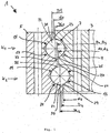
- FIG. 1 is a cross-sectional view through an inventive slewing bearing according to a first embodiment of the invention shown in detail.
- the slewing bearing 1 has an inner ring 3 and an outer ring 5.
- This in FIG. 1 shown large rolling bearing 1 is a double-row slewing bearing with a first row of balls K1 and a second row of balls K2.
- the second row of balls K2 is axially spaced from the first row of balls K1.
- the first ball row K1 includes a plurality of balls 22 arranged along a pitch diameter DL1.
- the second ball row K2 includes a plurality of balls 24 arranged along a second pitch diameter in DL2.
- the inner ring 3 has a first raceway section 7 and a second raceway section 9, which are associated with the first ball row K1.
- the inner ring 3 has a third raceway section 11 and a fourth raceway section 13, which are associated with the second ball row K2.
- the first raceway section 7 and the second raceway section 9 are arranged adjacent to each other and separated from each other by a circumferential annular groove.
- the first raceway section 7 is bounded by an annular first inner shoulder 23.
- the second raceway section 9 is bounded by an annular second inner shoulder 25.
- the first inner shoulder 23 has a maximum diameter d1.
- the second inner shoulder 25 has a second maximum diameter d2.
- the maximum diameter d1 of the first inner shoulder 23 is greater than the maximum diameter d2 of the second inner shoulder 25.
- the third raceway section 11 and the fourth raceway section 13 are arranged adjacent to each other in the inner ring 3 and separated from each other by a circumferential annular groove.
- the third raceway section 11 is bounded by an annular third inner shoulder 27.
- the fourth raceway section 13 is bounded by an annular fourth inner shoulder 29.
- the third inner shoulder 27 has a maximum diameter d3. In the in FIG. 1 In the embodiment shown, the maximum diameter d3 of the third inner shoulder 27 corresponds to the maximum diameter d2 of the second inner shoulder 25.
- the fourth inner shoulder 29 has a maximum diameter d4. In the in FIG. 1 In the embodiment shown, the maximum diameter d3 of the third inner shoulder 27 is greater than the maximum diameter d4 of the fourth inner shoulder 29.
- corresponding external shoulders are formed to the inner shoulders of the inner ring, which each define a likewise provided in the outer ring 5 raceway section.
- the outer ring 5 has in particular a first raceway section 15, and a second raceway section 17, which are associated with the first ball row K1.
- the outer ring 5 has a third raceway section 19 and a fourth raceway section 21, which are associated with the second ball row K2.
- the first raceway section 15 in the outer ring 5 is formed to the - relative to the ball 22 - diametrically opposite second raceway section 9 of the inner ring 3.
- the second raceway portion 17 in the outer ring 5 is formed corresponding to the -related to the ball 22 - diametrically opposite first raceway portion 7 of the inner ring 3.
- the third raceway section 19 in the outer ring 5 is formed corresponding to the - related to the ball 24 - diametrically opposite fourth raceway section 13 in the inner ring 3.
- the fourth raceway section 21 in the outer ring 5 is formed corresponding to the third raceway section 11 diametrically opposite in relation to the ball 24 in the inner ring 3.
- the first raceway section 15 is bounded by a first annular outer shoulder 31, which has a minimum diameter D1.
- the second raceway portion 17 is bounded by a second annular outer shoulder 33 which has a minimum diameter of D2.
- the third raceway section 19 is bounded by a third annular outer shoulder 35 which has a minimum diameter D3.
- the fourth raceway section 21 is bounded by an annular fourth outer shoulder 37, which has a minimum diameter D4.
- the balls 22 of the first row of balls K1 are arranged along a first circle diameter DL1.
- the balls 24 of the second row of balls K2 are arranged along a second circle diameter DL2.
- DL1 is according to FIG. 1 bigger than DL2.
- the area of the first raceway section 7 of the inner ring 3 is increased by the diameter d1 of the first inner shoulder 23 being larger than the diameter d2 of the second inner shoulder 25.
- d1 is also larger than DL1.
- the area of the second raceway portion 17 of the outer race is increased corresponding to the area of the first raceway portion 7 of the inner race 3 by the diameter D2 being smaller than the diameter D1 of the first outer shoulder 31.
- the diameter D2 of the second outer shoulder 33 is smaller by the same amount as the first pitch diameter DL1, as the diameter d1 of the first inner shoulder 23 is larger than DL1.
- the third raceway portion 11 has an enlarged area equal to the area of the fourth raceway portion 21 of the outer race 5.
- the diameter d3 of the third inner shoulder 27 is greater by the same amount than the running diameter DL2 of the second ball race K2, such as Diameter D4 of the fourth outer shoulder 37 of the fourth raceway section 21 of the outer ring 5 is less than the second running circle diameter DL2.
- the relation to the balls 24 diametrically opposite raceway sections 13 and 19 of the inner ring 3 and outer ring 5 are reduced in the same way relative to the raceway sections 11 and 21, as already discussed above with respect to the first ball row K1 and the raceway sections 9 and 15 ,
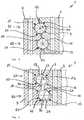
- FIG. 2 shows a slewing bearing 1 of the present invention according to a second embodiment.
- the slewing bearing 1 according to FIG. 2 similar in structure to the large rolling bearing 1 according to FIG. 1 with regard to the arrangement of the first ball row K1 and second ball row K2.
- the explanations are given in this regard FIG. 1 referred, as far as identical reference numerals were assigned.
- the embodiments of the FIGS. 1 and 2 differ, however, in terms of sizing the shoulders.
- the inner ring 3 according to FIG. 2 is designed in particular as follows:
- the first inner shoulder 23 of the inner ring 3 has a maximum diameter d1, which is equal to the running circle diameter DL1 of the first ball row K1.
- the minimum diameter D1 of the first outer shoulder 31 of the outer ring 5 is greater than the running circle diameter DL1 of the first ball row K1.
- the second inner shoulder 25 of the inner ring 3 has a maximum diameter d2 which is smaller than the running circle diameter DL1 of the first ball row K1.
- the corresponding minimum diameter D2 in the outer ring 5 of the second outer shoulder 33 has a minimum diameter D2, which is equal to the running circle diameter DL1 of the first ball row K1.
- the maximum diameter d3 of the third inner shoulder 27 in the inner ring 3 is equal to the maximum diameter d1 of the first inner shoulder 23 of the first ball row K1.
- the running circle diameter DL1 of the first ball row K1 corresponds to that in FIG FIG. 2 embodiment shown also the running circle diameter of the second ball row K2.
- the minimum diameter D3 of the third outer shoulder 35 in the outer ring 5 is again larger than the running circle diameter DL1. D3 is equal to D1.
- the maximum diameter d4 of the fourth inner shoulder 29 of the inner ring 3 is equal to the diameter d2 of the second inner shoulder 25.
- the corresponding minimum diameter D4 of the fourth outer shoulder 37 of the outer ring 5 is equal to the minimum diameter D2 of the second outer shoulder 33.
- FIG. 2 serves the running circle diameter DL1 as a reference size.
- a gap is formed in each case, which varies by the same amount in the direction of the outer ring or inner ring, whereby diametrically opposite (based on the respective row of balls K1, K2) evenly enlarged and reduced track sections are formed.
- the inner ring 3 can be pushed completely through the outer ring 3 because there is no overlap.
- FIGS. 3 and 4 first show a large roller bearing 101 from the prior art.
- the slewing bearing 101 has an inner ring 103 and an outer ring 105. Between the inner ring 103 and the outer ring 105, two rows of balls K11 and K12 are arranged.
- the large-diameter bearing 101 of the prior art is a double-row four-point bearing.
- the balls of the first ball row K11 each have two points of contact with the inner ring 103 and the outer ring 105. The points of contact are each arranged in a separate raceway section 107, 109, 115 and 117.
- FIG. 4 shows the camp FIG. 3 when a large overlying axial load is introduced via the inner ring and acts on the bearing.
- the inner ring 103 is pressed against the outer ring 105 down. Due to the employment of the balls of the first row of balls K11 and the second row of balls K12 against the surfaces of the raceway portions of the inner ring 103 and the outer ring 105 are driven apart, which in FIG. 4 is shown overdrawn.
- the pressure angle ⁇ which now assumes the value ⁇ 2.
- FIGS. 5 and 6 show the improved function of the large rolling bearing according to the present invention.
- the in the FIGS. 5 and 6 Operation shown applies to both embodiments of the present invention, for the sake of simplicity, however, reference is only made to the first embodiment of the invention, which is also in FIG. 1 already shown and explained.
- FIG. 5 is the slewing bearing off FIG. 1 shown in a substantially unloaded condition.
- the points of contact of the balls 22, 24 of the first and second rows of balls K1, K2 are aligned substantially at an angle of ⁇ 1 to the radial direction of the bearing with respect to the center of the balls.
- FIG. 6 shown state loads a thrust load on the inner ring, which in the orientation shown in FIG FIG.
- the surface of the raceway sections 9, 15 of the first ball row K1 and the surface of the raceway sections 13, 19 of the second ball row K2 are substantially unloaded, but in any case much less heavily loaded than the aforementioned surfaces of the raceway sections, 7, 11, 17, 21st
- the ellipse 26 is not in the region of the annular shoulders 23, 33, 27, 37 despite the strong axial load. Consequently, no wear of the balls and / or raceway sections occurs of the inner ring 3 and outer ring 5.
- no critical operating state has yet been reached in the bearing according to the invention.
- the present embodiments of preferred embodiments and the above description of the figures relate to double-row bearings.
- the invention relates
- multi-row embodiments of the large rolling bearing according to the present invention in particular, the invention relates to a three-row slewing bearing, which has a third row of balls.
- the third row of balls is arranged between the inner ring and the outer ring in a four-point bearing, wherein the third row of balls is axially spaced from the first row of balls and the second row of balls, wherein the third row of balls are associated with four track portions, each having a surface for receiving the ball track, and wherein the surface of each one provided in the inner ring raceway section of the third ball row is larger than the surface of each adjacent provided in the inner ring raceway section of the third row of balls and equal to the surface of the respective diametrically opposite provided in the outer ring raceway section of the third row of balls.
- Preferred embodiments which have been described above with reference to double-row versions of the large rolling bearing, are to be transferred in an analogous manner to the three-row design of the large roller bearing.
- the large rolling bearings according to the invention are preferably adapted to different deployment areas by means of further design details.
- the large rolling bearings according to the invention for example, have internal teeth, external teeth or no teeth.
- the large rolling bearings may have continuous, axially extending mounting holes or other, flange or radial mounting holes.
- the bearings according to the invention preferably have spacers between the balls, or cages for holding the balls.
- the large rolling bearings according to the invention have lubrication holes for filling and squeezing of lubricants, or openings for filling or removing the balls from the rows of balls.
Description
- Die vorliegende Erfindung betrifft ein Großwälzlager, welches als mehrreihige Kugeldrehverbindung zur Aufnahme von Axiallasten, Radiallasten und Kippmomenten ausgebildet ist, mit einem Außenring, einem Innenring, einer ersten Kugelreihe und einer zweiten Kugelreihe, wobei die erste Kugelreihe und die zweite Kugelreihe axial zueinander beabstandet jeweils in einer Vierpunktlagerung angeordnet sind, wobei der ersten Kugelreihe vier Laufbahnabschnitte und der zweiten Kugelreihe vier Laufbahnabschnitte zugeordnet sind, die jeweils eine Fläche zur Aufnahme der Kugellaufbahn aufweisen.
- Großwälzlager werden im Maschinen- und Anlagenbau zum Herstellen einer Drehverbindung bei großen Lasten eingesetzt. Man spricht insbesondere bei Laufkreisdurchmessern von 300 mm und größer von Großwälzlagern. Je nach Einbaubedingung und in Abhängigkeit der aufzunehmenden Kräfte betragen die Laufkreisdurchmesser der Großwälzlager durchaus auch mehrere 1000 mm. Bei Lagern dieser Größenordnung weisen die Großwälzlager selbst ein beträchtliches Eigengewicht auf und erfordern einen beträchtlichen Montageaufwand. Vor diesem Hintergrund wird die Verwendung integrierter Lager angestrebt, welche eine einzige montierbare Einheit aufweisen, die zur Aufnahme von Axialkräften, Radialkräften und gegebenenfalls Kippmomenten eingerichtet sind. Aus diesem Grund werden hauptsächlich Wälzlager in mehrreihiger Bauform eingesetzt, wenn die Aufnahme von Axialkräften, Radialkräften und Kippmomenten gefordert ist. Bekannt ist u.a. der Einsatz mehrreihiger Vierpunktlager.
- Konstrukteure sind bei der Auswahl des richtigen Lagers dem Zielkonflikt ausgesetzt, ein Lager mit möglichst hoher Belastbarkeit bei geringstem Einbauraum und möglichst geringem Montageaufwand vorzusehen. In Fällen, wo konstruktionsbedingt ein vorgegebener, begrenzter Bauraum eingehalten werden muss, oder (seltenen) Fällen des Nachrüstens von Großwälzlagern in einer bestehenden Umgebung mit dem Ziel, ein Lager mit höherer Belastbarkeit nachzurüsten (im Vergleich zu dem zuvor dort verbauten), besteht das Problem, dass eine höhere Stabilität mit bekannten Lagertypen nicht ohne Weiteres erreicht wird, ohne in axialer oder radialer Richtung einen größeren Bauraum bereitzustellen, was mit hohem konstruktiven Aufwand verbunden ist.
- Als Stand der Technik wird an dieser Stelle allgemein auf folgende Dokumente hingewiesen:
DE 10 2008 049 813 A1 ,DE 10 2004 023 774 A1 ,DE 10 2004 051 054 A1 ,DD 46 126 A5 DE 18 55 303 U undDE 10 2006 031 956 A1 . -
US-A-2011/0085756 zeigt die Merkmale des Oberbegriffs von Anspruch 1. - Vor diesem Hintergrund lag der vorliegenden Erfindung die Aufgabe zu Grunde, ein Großwälzlager der eingangs genannten Art mit verbesserter Lastaufnahme bei möglichst geringen Einbaumaßen bereitzustellen.
- Die Erfindung löst die ihr zu Grunde liegende Aufgabe bei einem Großwälzlager der eingangs genannten Art, indem das Großwälzlager nach Anspruch 1 ausgebildet ist, wobei die Fläche jeweils eines in dem Innenring vorgesehenen Laufbahnabschnitts größer als die Fläche des jeweils benachbarten in dem Innenring vorgesehenen Laufbahnabschnitts ist und gleich der Fläche des jeweils diametral gegenüberliegenden in dem Außenring vorgesehenen Laufbahnabschnitts ist. Die Erfindung beruht auf der Erkenntnis, dass die Kugelreihe eines Vierpunktlagers insgesamt vier Berührungspunkte mit jeweils separaten Flächenabschnitten im Innen- und Außenring aufweist. Diese Berührpunkte sind nicht konstant an derselben Stelle - bezogen auf den Querschnitt des Lagers - sondern verändern sich in Abhängigkeit der Lastsituation. Dies gilt auch für den Fall der Lastumkehr. Je größer die auf das Lager wirkende Kraft in axialer Richtung wird, desto stärker verschiebt sich der Berührungspunkt in den belasteten Laufbahnabschnitten in Richtung des Lagerspaltes zwischen dem Innenring und dem Außenring. Dies ist der Tatsache geschuldet, dass die Kugeln und Laufbahnflächen infolge der auftretenden Axialkraft einer Verformung ausgesetzt sind und jeweils mit dem Laufbahnabschnitt einen flächigen Kontakt herstellen. Um eine gewisse Lauftoleranz erzielen zu können, ist bei Vierpunktlagern der Krümmungsradius der Kugeln geringfügig kleiner als der Krümmungsradius der korrespondierenden Laufbahnabschnitte (im Querschnitt). Dies bewirkt, dass beim Auftreten großer Axialkräfte der Innenring und der Außenring eine auseinandertreibende Kraftbeaufschlagung erfahren, wodurch der Kontaktbereich zwischen den jeweiligen Kugeln und der korrespondierenden, belasteten Laufbahnfläche wandern kann. Erfindungsgemäß werden insbesondere diejenigen Flächen der Laufbahnabschnitte vergrößert, welche bei einer Vorzugsbelastung des Großwälzlagers stärker belastet werden. Unabhängig davon, ob es sich bei der Last um eine aufliegende Last oder eine anhebende Last handelt, ist das Lager erfindungsgemäße so auszugestalten, dass die jeweils in Vorzugsrichtung stärker belasteten Flächen der Laufbahnabschnitte vergrößert sind.
- Da jeder Laufbahnabschnitt in dem Lager endlich ist, ist bei Erreichen einer kritischen Axiallast ein Punkt erreicht, an welchem der Kontaktbereich zwischen Kugel und Laufbahnfläche (im Sinne von: für die Laufbahn zur Verfügung stehende Fläche) an die Kante der Laufbahnfläche oder darüber hinaus wandert. Infolge dessen werden sowohl die Kugeln als auch die Kanten der Laufbahnabschnitte starkem Verschleiß ausgesetzt.
- Auf diesen Erkenntnissen aufbauend macht sich die Erfindung zu Nutze, dass beim Konzipieren der Lagerung bereits bekannt ist, in welche Richtung - axial betrachtet - die Belastung auf das Lager größer sein wird. Das Lager kann also gezielt darauf abgestimmt sein, aus einer axialen Richtung höhere Lasten aufzunehmen als aus der anderen Richtung. Weil auf Grund der Axiallast immer zwei diagonal gegenüberliegende Laufbahnabschnitte stärker belastet werden als die jeweils anderen gegenüberliegenden Laufbahnabschnitte, nutzt die Erfindung die Kenntnis über die Verschiebung des Kontaktbereiches innerhalb der Laufbahnflächen, indem die erwartungsgemäß stärker belasteten Flächen im Vergleich zu den erwartungsgemäß weniger belasteten Flächen vergrößert sind. Der zusätzliche Bauraum, den man in Folge einer Flächenvergrößerung benötigt, kann auf diese Weise dadurch kompensiert werden, dass man die jeweils korrespondierende, geringer belastete Fläche entsprechend der Vergrößerung der einen Fläche verkleinert.
- Die Erfindung wird dadurch vorteilhaft weitergebildet, dass die Fläche des in dem Innenring vorgesehenen Laufbahnabschnitts gleich der Fläche des jeweils diametral gegenüberliegenden dem Außenring vorgesehenen Laufbahnabschnitts ist.
- Weiter vorzugsweise sind die jeweils größeren Flächen der Laufbahnabschnitte gleich groß. Unter gleich großen Flächen wird vorliegend verstanden, dass unter Berücksichtigung fertigungstechnischer Toleranzen die Länge einer Laufbahnfläche im Querschnitt sich nicht um mehr als +/- 3 % ändern soll.
- Wenn wie zuvor oder im Folgenden von Flächen die Rede ist, wird im Allgemeinen die Querschnittsfläche gemeint und nicht die tatsächliche umlaufende Fläche.
- In einer ersten beanspruchten Alternative der Erfindung weist der Innenring für die erste Kugelreihe eine ringförmige erste Innenschulter und eine ringförmige zweite Innenschulter auf, welche jeweils eine der Flächen zur Aufnahme einer Kugellaufbahn der ersten Kugelreihe begrenzen. Zusätzlich weist der Innenring für die zweite Kugelreihe eine ringförmige dritte Innenschulter und eine ringförmige vierte Innenschulter auf, welche jeweils eine der Flächen zur Aufnahme der Kugellaufbahn der zweiten Kugelreihe begrenzen, wobei ein maximaler Durchmesser der vierten Innenschulter von einem maximalen Durchmesser der ersten Innenschulter verschieden ist. Durch die Vergrößerung der Durchmesser der Innenschultern in vorstehend genannter Weise ist eine Flächenvergrößerung in geometrisch einfach vorhersehbarer und berechenbarer Weise ermöglicht, ohne die Geometrie des Lagers insgesamt vollständig neu auslegen zu müssen.
- In der vorbezeichneten ersten Alternative ist der maximale Durchmesser der dritten Innenschulter von dem maximalen Durchmesser der zweiten Innenschulter verschieden.
- In einer zweiten beanspruchten Alternative weist der Außenring alternativ oder zusätzlich für die erste Kugelreihe eine erste ringförmige Außenschulter und eine zweite ringförmige Außenschulter auf, welche jeweils eine der Flächen zur Aufnahme der Kugellaufbahnen der ersten Kugelreihe begrenzen. Der Außenring weist zusätzlich für die zweite Kugelreihe eine dritte ringförmige Außenschulter und eine vierte ringförmige Außenschulter auf, welche jeweils eine der Flächen zur Aufnahme der Kugellaufbahnen der zweiten Kugelreihe begrenzen, wobei der minimale Durchmesser der vierten Außenschulter von dem minimalen Durchmesser der ersten Außenschulter verschieden ist. Der Außenring und die in dem Außenring vorgesehenen Laufbahnabschnitte sind vorzugsweise korrespondierend zu den jeweiligen Abschnitten des Innenrings ausgestaltet, um eine sich symmetrisch ergebene Verschiebung des Kontaktbereichs zwischen den Kugeln und den Flächen der Laufbahnabschnitte sowohl im Innenring als auch im Außenring gleichermaßen zu kompensieren.
- In der zweiten beanspruchten Alternative ist der minimale Durchmesser der dritten Außenschulter von dem minimalen Durchmesser der zweiten Außenschulter verschieden.
- In einer besonders bevorzugten Ausführungsform der Erfindung ist der größte der maximalen Durchmesser der Innenschultern kleiner oder gleich dem geringsten der minimalen Durchmesser der Außenschultern. Diese Ausführungsform hat den zusätzlichen Vorteil, dass der Innenring trotz einer erfindungsgemäßen Vergrößerung der erwartungsgemäß stärker belasteten Flächen der Laufbahnabschnitte nach wie vor komplett durch den Außenring hindurchsteckbar ist, wodurch die Montage und Demontage des Lagers erheblich vereinfacht ist.
- Die Kugeln der ersten Kugelreihe sind in einer bevorzugten Ausführungsform gemeinsam mit den Kugeln der zweiten Kugelreihe entlang eines ersten Laufkreisdurchmessers angeordnet.
- Vorzugsweise ist der größte der maximalen Durchmesser der Innenschultern und/oder der geringste der minimalen Durchmesser der Außenschultern gleich oder in einem Bereich von bis zu 0,5 mm unterhalb des ersten Laufkreisdurchmessers der ersten und zweiten Kugelreihe.
- Weiter vorzugsweise ist der geringste der minimalen Durchmesser der Außenschultern gleich oder in einem Bereich von bis zu 0,5 mm oberhalb des ersten Laufkreisdurchmessers der ersten und zweiten Kugelreihe.
- Gemäß einer vorteilhaften Weiterbildung dieser Ausführungsform ist der maximale Durchmesser der ersten Innenschulter gleich dem maximalen Durchmesser der dritten Innenschulter und größer als der maximale Durchmesser der jeweils zweiten und vierten Innenschulter.
- Weiter vorzugsweise ist der minimale Durchmesser der zweiten Außenschulter gleich dem minimalen Durchmesser der vierten Außenschulter und geringer als der minimale Durchmesser der jeweils ersten und dritten Außenschulter.
- Gemäß einer alternativen Ausführungsform sind die Kugeln der ersten Kugelreihe entlang des ersten Laufkreisdurchmessers angeordnet, und die Kugeln der zweiten Kugelreihe entlang eines zweiten Laufkreisdurchmessers angeordnet, welcher von dem Durchmesser der ersten Kugelreihe verschieden ist. Hierdurch ergibt sich der Vorteil, dass der mögliche Druckwinkel, also die mögliche Verlagerung der Berührpunkte in Richtung des Spaltes zwischen Innenring- und Außenring des Lagers in einem wesentlich größeren Maße veränderbar ist, als es der Fall wäre, wenn die Kugeln aller Reihen auf einem gleichen Laufkreisdurchmesser angeordnet wären. Das Ausmaß der Steigerung erfolgt in Abhängigkeit der Größe des Versatzes zwischen dem ersten Laufkreisdurchmesser und dem zweiten Laufkreisdurchmesser.
- Gemäß dieser alternativen Ausführungsform ist vorzugsweise der maximale Durchmesser der ersten Innenschulter größer als der maximale Durchmesser der zweiten Innenschulter und der maximale Durchmesser der dritten Innenschulter größer als der maximale Durchmesser der vierten Innenschulter.
- Weiter vorzugsweise ist der minimale Durchmesser der vierten Außenschulter geringer als der minimale Durchmesser der dritten Außenschulter, und der minimale Durchmesser der zweiten Außenschulter ist geringer als der minimale Durchmesser der ersten Innenschulter.
- Gemäß einer weiteren bevorzugten Ausführungsform besteht die erste Kugelreihe aus Kugeln mit einem ersten Kugeldurchmesser und die zweite Kugelreihe besteht aus Kugeln mit einem zweiten Kugeldurchmesser, welcher von dem ersten Kugeldurchmesser verschieden ist.
- Gemäß einer weiteren bevorzugten Ausführungsform weist das Großwälzlager eine oder mehrere weitere Kugelreihen auf. Die eine oder mehreren weiteren Kugelreihen sind vorzugsweise entsprechend der ersten Kugelreihe und/oder der zweiten Kugelreihe gemäß den vorstehend erläuterten bevorzugten Ausführungsformen ausgebildet. Dies betrifft insbesondere die Ausgestaltung gegenüberliegender Schultern, Laufbahnabschnitte, Kugeldurchmesser und/oder Laufkreisdurchmesser. Gemäß einer besonders bevorzugten Ausführungsform weist das Großwälzlager eine dritte Kugelreihe auf.
- Die Erfindung betrifft weiterhin eine Windenergieanlage mit einem Turm, der einen Turmkopf aufweist und einer Gondel, welche zur Aufnahme eines Rotors eingerichtet ist, wobei die Gondel mittels eines Azimutlagers relativ zu dem Turm drehbar gelagert ist. Die vorstehend genannte Windenergieanlage wird erfindungsgemäß dadurch verbessert, dass das Azimutlager als ein Großwälzlager gemäß einer der vorstehend erläuterten bevorzugten Ausführungsformen beschrieben ist.
- Im Folgenden wird die Erfindung anhand zweier bevorzugter Ausführungsbeispiele und unter Bezugnahme auf die beiliegenden Figuren näher beschrieben. Hierbei zeigen:
- Figur 1
- eine Detailansicht eines Großwälzlagers gemäß eines ersten Ausführungsbeispiels der Erfindung;
- Figur 2
- eine Detailansicht eines Großwälzlagers gemäß einem zweiten Ausführungsbeispiel der vorliegenden Erfindung;
- Figur 3
- ein Großwälzlager aus dem Stand der Technik in einem ersten Zustand;
- Figur 4
- das Großwälzlager aus
Figur 3 in einem zweiten Zustand; - Figur 5
- eine Detailansicht des Großwälzlagers gemäß dem ersten Ausführungsbeispiel in einem ersten Zustand, ähnlich
Figur 3 ; und - Figur 6
- eine Detailansicht des Großwälzlagers gemäß dem ersten Ausführungsbeispiel der Erfindung in einem zweiten Zustand, ähnlich
Figur 4 . - Die nachfolgend näher beschriebenen Figuren erläutern die Erfindung anhand einer beispielhaften Lastsituation. Diese Lastsituation stellt eine aufliegende Last dar, die in - bezogen auf die
Figuren 1 bis 6 - vertikaler Richtung von oben auf den Innenring des jeweils abgebildeten Lagers wirkt. Es ist ersichtlich, dass die entsprechende Ausbildung und Nummerierung der Schultern und Kugelreihen in Abhängigkeit vom Lastfall unter Berücksichtigung der Orientierung der Lager in den Figuren umgekehrt werden kann, um einen jeweils anderen Lastfall abzubilden. - In
Figur 1 ist eine Querschnittsansicht durch ein erfindungsgemäßes Großwälzlager gemäß einem ersten Ausführungsbeispiel der Erfindung im Detail gezeigt. Das Großwälzlager 1 weist einen Innenring 3 und einen Außenring 5 auf. Das inFigur 1 dargestellte Großwälzlager 1 ist ein zweireihiges Großwälzlager mit einer ersten Kugelreihe K1 und einer zweiten Kugelreihe K2. Die zweite Kugelreihe K2 ist von der ersten Kugelreihe K1 axial beabstandet. Die erste Kugelreihe K1 umfasst eine Vielzahl von Kugeln 22, welche entlang eines Laufkreisdurchmessers DL1 angeordnet sind. Die zweite Kugelreihe K2 umfasst eine Vielzahl von Kugeln 24, welche entlang eines zweiten Laufkreisdurchmessers in DL2 angeordnet sind. - Der Innenring 3 weist einen ersten Laufbahnabschnitt 7 und einen zweiten Laufbahnabschnitt 9 auf, welche der ersten Kugelreihe K1 zugeordnet sind. Zudem weist der Innenring 3 einen dritten Laufbahnabschnitt 11 und einen vierten Laufbahnabschnitt 13 auf, welche der zweiten Kugelreihe K2 zugeordnet sind. Der erste Laufbahnabschnitt 7 und der zweite Laufbahnabschnitt 9 sind benachbart zueinander angeordnet und durch eine umlaufende Ringnut voneinander separiert. Der erste Laufbahnabschnitt 7 ist von einer ringförmigen ersten Innenschulter 23 begrenzt. Der zweite Laufbahnabschnitt 9 ist von einer ringförmigen zweiten Innenschulter 25 begrenzt. Die erste Innenschulter 23 weist einen maximalen Durchmesser d1 auf. Die zweite Innenschulter 25 weist einen zweiten maximalen Durchmesser d2 auf. Der maximale Durchmesser d1 der ersten Innenschulter 23 ist hierbei größer als der maximale Durchmesser d2 der zweiten Innenschulter 25.
- Der dritte Laufbahnabschnitt 11 und der vierte Laufbahnabschnitt 13 sind zueinander benachbart in dem Innenring 3 angeordnet und voneinander durch eine umlaufende Ringnut separiert. Der dritte Laufbahnabschnitt 11 ist durch eine ringförmige dritte Innenschulter 27 begrenzt. Der vierte Laufbahnabschnitt 13 ist durch eine ringförmige vierte Innenschulter 29 begrenzt. Die dritte Innenschulter 27 weist einen maximalen Durchmesser d3 auf. In dem in
Figur 1 gezeigten Ausführungsbeispiel entspricht der maximale Durchmesser d3 der dritten Innenschulter 27 dem maximalen Durchmesser d2 der zweiten Innenschulter 25. Die vierte Innenschulter 29 weist einen maximalen Durchmesser d4 auf. In dem inFigur 1 gezeigten Ausführungsbeispiel ist der maximale Durchmesser d3 der dritten Innenschulter 27 größer als der maximale Durchmesser d4 der vierten Innenschulter 29. - In dem Außenring 5 sind zu den Innenschultern des Innenrings 3 korrespondierende Außenschultern ausgebildet, welche jeweils einen ebenfalls in dem Außenring 5 vorgesehenen Laufbahnabschnitt begrenzen. Der Außenring 5 weist insbesondere einen ersten Laufbahnabschnitt 15, und einen zweiten Laufbahnabschnitt 17 auf, welche der ersten Kugelreihe K1 zugeordnet sind. Zudem weist der Außenring 5 einen dritten Laufbahnabschnitt 19 und einen vierten Laufbahnabschnitt 21 auf, welcher der zweiten Kugelreihe K2 zugeordnet sind. Der erste Laufbahnabschnitt 15 in dem Außenring 5 ist zu dem - bezogen auf die Kugel 22 - diametral gegenüberliegenden zweiten Laufbahnabschnitt 9 des Innenrings 3 ausgebildet. Der zweite Laufbahnabschnitt 17 in dem Außenring 5 ist zu dem -bezogen auf die Kugel 22 - diametral gegenüberliegenden ersten Laufbahnabschnitts 7 des Innenrings 3 korrespondierend ausgebildet.
- Der dritte Laufbahnabschnitt 19 in dem Außenring 5 ist zu dem - bezogen auf die Kugel 24 - diametral gegenüberliegenden vierten Laufbahnabschnitt 13 in dem Innenring 3 korrespondierend ausgebildet. Der vierte Laufbahnabschnitt 21 in dem Außenring 5 ist zu dem - bezogen auf die Kugel 24 - diametral gegenüberliegenden dritten Laufbahnabschnitt 11 in dem Innenring 3 korrespondierend ausgebildet.
- Der erste Laufbahnabschnitt 15 ist durch eine erste ringförmige Außenschulter 31 begrenzt, welche einen minimalen Durchmesser D1 aufweist. Der zweite Laufbahnabschnitt 17 ist durch eine zweite ringförmige Außenschulter 33 begrenzt, welche einen minimalen Durchmesser von D2 aufweist. Der dritte Laufbahnabschnitt 19 ist durch eine dritte ringförmige Außenschulter 35 begrenzt, welche einen minimalen Durchmesser D3 aufweist. Der vierte Laufbahnabschnitt 21 ist durch eine ringförmige vierte Außenschulter 37 begrenzt, welche einen minimalen Durchmesser D4 aufweist.
- Die Kugeln 22 der ersten Kugelreihe K1 sind entlang eines ersten Laufkreisdurchmessers DL1 angeordnet. Die Kugeln 24 der zweiten Kugelreihe K2 sind entlang eines zweiten Laufkreisdurchmessers DL2 angeordnet. DL1 ist gemäß
Figur 1 größer als DL2. - Die Fläche des ersten Laufbahnabschnitts 7 des Innenrings 3 ist vergrößert, indem der Durchmesser d1 der ersten Innenschulter 23 größer ist als der Durchmesser d2 der zweiten Innenschulter 25.
- Gemäß
Figur 1 ist d1 ebenfalls größer als DL1. Die Fläche des zweiten Laufbahnabschnitts 17 des Außenrings ist korrespondierend zu der Fläche des ersten Laufbahnabschnitts 7 des Innenrings 3 vergrößert, indem der Durchmesser D2 geringer ist als der Durchmesser D1 der ersten Außenschulter 31. Der Durchmesser D2 der zweiten Außenschulter 33 ist um das gleiche Maß geringer als der erste Laufkreisdurchmesser DL1, wie der Durchmesser d1 der ersten Innenschulter 23 größer ist als DL1. - In analoger Weise zur ersten Kugelreihe K1 sind auch die Laufbahnabschnitte der zweiten Kugelreihe K2 ausgebildet. Der dritte Laufbahnabschnitt 11 weist eine vergrößerte Fläche auf, die genau so groß ist wie die Fläche des vierten Laufbahnabschnitts 21 des Außenrings 5. Der Durchmesser d3 der dritten Innenschulter 27 ist um den gleichen Betrag größer als der Laufkreisdurchmesser DL2 der zweiten Kugelreihe K2, wie der Durchmesser D4 der vierten Außenschulter 37 des vierten Laufbahnabschnitts 21 des Außenrings 5 geringer ist als der zweite Laufkreisdurchmesser DL2. Die bezogen auf die Kugeln 24 diametral gegenüberliegenden Laufbahnabschnitte 13 und 19 des Innenrings 3 bzw. Außenrings 5 sind in gleicher Weise relativ zu den Laufbahnabschnitten 11 und 21 verkleinert, wie vorstehend bereits in Bezug auf die erste Kugelreihe K1 und die Laufbahnabschnitte 9 und 15 erörtert wurde.
-
Figur 2 zeigt ein Großwälzlager 1 der vorliegenden Erfindung nach einem zweiten Ausführungsbeispiel. Das Großwälzlager 1 gemäßFigur 2 ähnelt in seiner Struktur dem Großwälzlager 1 gemäßFigur 1 im Hinblick auf die Anordnung der ersten Kugelreihe K1 und zweiten Kugelreihe K2. In Bezug auf die Innenschultern, die von ihnen begrenzten Laufbahnabschnitte, die Außenschultern und die von diesen begrenzten Laufbahnabschnitte wird insoweit auf die Erläuterungen zuFigur 1 verwiesen, soweit identische Bezugszeichen vergeben wurden. - Die Ausführungsbeispiele der
Figuren 1 und2 unterscheiden sich allerdings im Hinblick auf die Dimensionierung der Schultern. Der Innenring 3 gemäßFigur 2 ist insbesondere wie folgt ausgestaltet:
Die erste Innenschulter 23 des Innenrings 3 weist einen maximalen Durchmesser d1 auf, welcher gleich dem Laufkreisdurchmesser DL1 der ersten Kugelreihe K1 ist. Der minimale Durchmesser D1 der ersten Außenschulter 31 des Außenrings 5 hingegen ist größer als der Laufkreisdurchmesser DL1 der ersten Kugelreihe K1. Die zweite Innenschulter 25 des Innenrings 3 weist einen maximalen Durchmesser d2 auf, welcher geringer ist als der Laufkreisdurchmesser DL1 der ersten Kugelreihe K1. Der korrespondierende minimale Durchmesser D2 in dem Außenring 5 der zweiten Außenschulter 33 weist einen minimalen Durchmesser D2 auf, welcher gleich dem Laufkreisdurchmesser DL1 der ersten Kugelreihe K1 ist. - Der maximale Durchmesser d3 der dritten Innenschulter 27 in dem Innenring 3 ist gleich dem maximalen Durchmesser d1 der ersten Innenschulter 23 der ersten Kugelreihe K1 ist. Der Laufkreisdurchmesser DL1 der ersten Kugelreihe K1 entspricht gemäß dem in
Figur 2 gezeigten Ausführungsbeispiel auch dem Laufkreisdurchmesser der zweiten Kugelreihe K2. Im Unterschied zuFigur 1 sind also die beiden Kugelreihen K1 und K2 auf einem gleichen Laufkreisdurchmesser DL1 angeordnet und axial zueinander beabstandet. Der minimale Durchmesser D3 der dritten Außenschulter 35 in dem Außenring 5 ist wiederum größer als der Laufkreisdurchmesser DL1. D3 ist gleich D1. - Der maximale Durchmesser d4 der vierten Innenschulter 29 des Innerings 3 ist gleich dem Durchmesser d2 der zweiten Innenschulter 25. Der korrespondierende minimale Durchmesser D4 der vierten Außenschulter 37 des Außenrings 5 ist gleich dem minimalen Durchmesser D2 der zweiten Außenschulter 33.
- Bei dem Ausführungsbeispiel gemäß
Figur 2 dient der Laufkreisdurchmesser DL1 als Referenzgröße. Zwischen dem Außenring und dem Innenring ist jeweils ein Spalt ausgebildet, welcher um den gleichen Betrag in Richtung des Außenrings oder Innenrings variiert, wodurch einander diametral gegenüberliegende (bezogen auf die jeweilige Kugelreihe K1, K2) gleichmäßig vergrößerte und verkleinerte Laufbahnabschnitte ausgebildet sind. Zugleich ist der Innenring 3 nach Entfernen der Kugeln 22, 24 bzw. vor dem Einführen der Kugeln 22, 24 vollständig durch den Außenring 3 hindurchsteckbar, weil es zu keiner Überschneidung kommt. - Anhand der
Figuren 3 bis 6 soll die Funktionsweise eines erfindungsgemäßen Großwälzlagers 1 im Vergleich zu einem Großwälzlager 101 aus dem Stand der Technik veranschaulicht werden.Figuren 3 und 4 zeigen zunächst ein Großwälzlager 101 aus dem Stand der Technik. Das Großwälzlager 101 weist einen Innenring 103 und einen Außenring 105 auf. Zwischen dem Innenring 103 und dem Außenring 105 sind zwei Kugelreihen K11 und K12 angeordnet. Das Großwälzlager 101 aus dem Stand der Technik ist ein zweireihiges Vierpunktlager. Die Kugeln der ersten Kugelreihe K11 weisen jeweils zwei Berührungspunkte mit dem Innenring 103 und dem Außenring 105 auf. Die Berührungspunkte sind jeweils in einen separaten Laufbahnabschnitt 107, 109, 115 und 117 angeordnet. Relativ zu einer radialen Achse ist Druckwinkel α1 ausgebildet. Für die zweite Kugelreihe K12 gilt in Bezug auf die Laufbahnabschnitte 111, 113, 119 und 121 das Gleiche wie für die erste Kugelreihe K11. Die Flächen der Laufbahnabschnitt 107, 109, 111, 113, 115, 117, 119 und 121 sind jeweils im Wesentlichen gleich groß. -
Figur 4 zeigt das Lager ausFigur 3 , wenn eine große aufliegende Axiallast über den Innenring eingeleitet wird und auf das Lager wirkt. Der Innenring 103 wird gegen den Außenring 105 nach unten gedrückt. Aufgrund der Anstellung der Kugeln der ersten Kugelreihe K11 und der zweiten Kugelreihe K12 gegen die Flächen der Laufbahnabschnitte werden der Innenring 103 und der Außenring 105 auseinandergetrieben, was inFigur 4 überzeichnet dargestellt ist. In Folge dieser Relativbewegung zwischen dem Innenring und dem Außenring und einer zusätzlichen Deformierung der Kugeln 122, 124 kommt es zu einer Erhöhung des Druckwinkels α, welcher nun den Wert α2 einnimmt. Auf Grund der Verformung der Kugeln und Laufbahnflächen ist die punktförmige Berührung einer Kugel zu der sie berührenden Fläche des Laufbahnabschnitts zu einer Fläche vergrößert, was in Bezug auf die zweite Kugelreihe K12 durch die Ellipse 126 angedeutet ist. Dieser Verformungsbereich befindet sich gemäß Darstellung ausFigur 4 im Bereich einer Kante, die den Laufbahnabschnitt 121 begrenzt. Das gleiche Phänomen zeigt sich aufgrund der symmetrischen Ausbildung des Lagers auch in Bezug auf die übrigen, stark belasteten Laufbahnabschnitte 111, 107 und 117. Es tritt starker Verschleiß auf, sowohl auf Seiten der Kugeln als auch auf Seiten der Laufbahnabschnitte. - In Abgrenzung zu den
Figuren 3 und 4 zeigen dieFiguren 5 und 6 die verbesserte Funktion des Großwälzlagers gemäß der vorliegenden Erfindung. Die in denFiguren 5 und 6 gezeigte Funktionsweise gilt für beide Ausführungsbeispiele der vorliegenden Erfindung, der Einfachheit halber wird allerdings lediglich auf das erste Ausführungsbeispiel der Erfindung Bezug genommen, welches auch inFigur 1 bereits gezeigt und erläutert ist. InFigur 5 ist das Großwälzlager ausFigur 1 in einem im Wesentlichen unbelasteten Zustand dargestellt. Die Berührungspunkte der Kugeln 22, 24 der ersten und zweiten Kugelreihe K1, K2 sind im Wesentlichen in einem Winkel von α1 zur Radialrichtung des Lagers bezogen auf den Mittelpunkt der Kugeln ausgerichtet. In dem inFigur 6 gezeigten Zustand lastet eine Axiallast auf dem Innenring, die in der gezeigten Orientierung inFigur 6 nach unten wirkt. Aufgrund der Anstellung der Kugeln 22, 24 der ersten Kugelreihe K1 und der zweiten Kugelreihe K2 gegen die Flächen der Laufbahnabschnitte werden der Innenring 3 und der Außenring 5 auseinandergetrieben. Infolgedessen verlagert sich der Kontakt der Kugeln 22, 24 mit den jeweiligen Laufbahnabschnitten. Eine aufgrund der Deformierung der Kugeln und Laufbahnflächen ausgebildete Kontaktfläche, dargestellt durch Ellipse 26, ist in Richtung der Innenschultern 23, 27 des Innenrings 3 und der Außenschultern 33, 37 des Außenrings 5 verlagert. Die Fläche der Laufbahnabschnitte 9, 15 der ersten Kugelreihe K1 und die Fläche der Laufbahnabschnitte 13, 19 der zweiten Kugelreihe K2 sind im Wesentlichen unbelastet, jedenfalls aber deutlich weniger stark belastet als die vorstehenden genannten Flächen der Laufbahnabschnitte, 7, 11, 17, 21. Allerdings befindet sich die Ellipse 26 auf Grund der erfindungsgemäß vergrößerten Fläche der Laufbahnabschnitte 7, 17, 11 und 21 trotz der starken Axiallast nicht in dem Bereich der ringförmigen Schultern 23, 33, 27, 37. Folglich tritt kein Verschleiß der Kugeln und/oder Laufbahnabschnitte des Innenrings 3 und Außenrings 5 auf. Bei ähnlicher Lastsituation und ähnlicher Druckwinkelverlagerung wie bei aus dem Stand der Technik bekannten Lagern (sieheFigur 3, 4 ) ist bei dem erfindungsgemäßen Lager noch kein kritischer Betriebszustand erreicht. - Die vorliegenden Ausführungen zu bevorzugten Ausführungsformen und die vorstehende Figurenbeschreibung beziehen sich auf zweireihige Lager. Die Erfindung betrifft darüberhinaus jedoch zusätzlich auch weitere, mehrreihige Ausführungsformen des Großwälzlagers gemäß der vorliegenden Erfindung. Insbesondere betrifft die Erfindung ein dreireihiges Großwälzlager, welches eine dritte Kugelreihe aufweist. Die dritte Kugelreihe ist zwischen dem Innenring und dem Außenring in einer Vierpunktlagerung angeordnet, wobei die dritte Kugelreihe zu der ersten Kugelreihe und der zweiten Kugelreihe axial beabstandet ist, wobei der dritten Kugelreihe vier Laufbahnabschnitte zugeordnet sind, die jeweils eine Fläche zur Aufnahme der Kugellaufbahn aufweisen, und wobei die Fläche jeweils eines in dem Innenring vorgesehenen Laufbahnabschnitts der dritten Kugelreihe größer ist als die Fläche des jeweils benachbarten in dem Innenring vorgesehenen Laufbahnabschnitts der dritten Kugelreihe und gleich der Fläche des jeweils diametral gegenüberliegenden in dem Außenring vorgesehenen Laufbahnabschnitts der dritten Kugelreihe ist.
- Bevorzugte Ausführungsformen, die vorstehend unter Bezugnahme auf zweireihige Ausführungen des Großwälzlagers geschildert wurden, sind in analoger Weise auch auf die dreireihige Ausführung des Großwälzlagers zu übertragen.
- Bevorzugte Ausführungsformen der vorliegenden Erfindung werden bevorzugt mittels weiterer konstruktiver Details an verschiedene Einsatzebereiche angepasst. So können die erfindungsgemäßen Großwälzlager beispielsweise eine Innenverzahnung, Außenverzahnung oder gar keine Verzahnung aufweisen. Die Großwälzlager können durchgehende, sich axial erstreckende Befestigungsbohrungen oder andere, flanschartige oder radiale Befestigungsbohrungen aufweisen. Weiterhin weisen die erfindungsgemäßen Lager vorzugsweise Abstandshalter zwischen den Kugeln auf, oder Käfige zum Halten der Kugeln. Gemäß weiterer bevorzugter Ausführungsformen verfügen die Großwälzlager gemäß der Erfindung über Schmierbohrungen zum Einfüllen und Auspressen von Schmiermitteln, oder etwa Öffnungen zum Einfüllen oder Entfernen der Kugeln aus den Kugelreihen.
Claims (14)
- Großwälzlager (1), welches als mehrreihige Kugeldrehverbindung zur Aufnahme von Axiallasten, Radiallasten und Kippmomenten ausgebildet ist, mit einem Außenring (5), einem Innenring (3), einer ersten Kugelreihe (K1) und einer zweiten Kugelreihe (K2), wobei die erste Kugelreihe (K1) und die zweite Kugelreihe (K2) axial zueinander beabstandet jeweils in einer Vierpunktlagerung angeordnet sind, wobei der ersten Kugelreihe vier Laufbahnabschnitte (7, 9, 15, 17) und der zweiten Kugelreihe vier Laufbahnabschnitte (11, 13, 19, 21) zugeordnet sind, die jeweils eine Fläche zur Aufnahme der Kugellaufbahn aufweisen,
wobei die Fläche jeweils eines in dem Innenring vorgesehenen Laufbahnabschnitts (7, 11) größer als die Fläche des jeweils benachbarten, in dem Innenring vorgesehenen Laufbahnabschnitts (9, 13) ist und gleich der Fläche des jeweils diametral gegenüberliegenden in dem Außenring vorgesehenen Laufbahnabschnitts (17, 21) ist;- der Innenring (3) für die erste Kugelreihe (K1) eine ringförmige erste Innenschulter (23) und eine ringförmige zweite Innenschulter (25) aufweist, welche jeweils eine der Flächen zur Aufnahme einer Kugellaufbahn der ersten Kugelreihe (K1) begrenzen, der Innenring (3) für die zweite Kugelreihe (K2) eine ringförmige dritte Innenschulter (27) und eine ringförmige vierte Innenschulter (29) aufweist, welche jeweils eine der Flächen zur Aufnahme der Kugellaufbahn der zweiten Kugelreihe (K2) begrenzen, wobei ein maximaler Durchmesser (d4) der vierten Innenschulter (29) von einem maximalen Durchmesser (d1) der ersten Innenschulter (23) verschieden ist,dadurch gekennzeichnet, dass der maximale Durchmesser (d3) der dritten Innenschulter (27) von dem maximalen Durchmesser (d2) der zweiten Innenschulter (25) verschieden ist, und/oder- der Außenring (5) für die erste Kugelreihe (K1) eine erste ringförmige Außenschulter (31) und eine zweite ringförmige Außenschulter (33) aufweist, welche jeweils eine der Flächen zur Aufnahme der Kugellaufbahnen der ersten Kugelreihe (K1) begrenzen, der Außenring (5) für die zweite Kugelreihe (K2) eine dritte ringförmige Außenschulter (35) und eine vierte ringförmige Außenschulter (37) aufweist, welche jeweils eine der Flächen zur Aufnahme der Kugellaufbahnen der zweiten Kugelreihe (K2) begrenzen, wobei der minimale Durchmesser (D4) der vierten Außenschulter (37) von dem minimalen Durchmesser (D1) der ersten Außenschulter (31) verschieden ist,dadurch gekennzeichnet, dass der minimale Durchmesser (D3) der dritten Außenschulter (35) von dem minimalen Durchmesser (D2) der zweiten Außenschulter (33) verschieden ist. - Großwälzlager (1) nach Anspruch 1,
dadurch gekennzeichnet, dass die Fläche des in dem Innenring (3) vorgesehenen Laufbahnabschnitts (9, 13) gleich der Fläche des jeweils diametral gegenüberliegenden in dem Außenring (5) vorgesehenen Laufbahnabschnitts (15, 19) ist. - Großwälzlager (1) nach einem der vorstehenden Ansprüche,
dadurch gekennzeichnet, dass der größte der maximalen Durchmesser (d1, d2, d3, d4) der Innenschultern (23, 25, 27, 29) kleiner oder gleich dem geringsten der minimalen Durchmesser (D1, D2, D3, D4) der Außenschultern (31, 33, 35, 37) ist. - Großwälzlager (1) nach einem der vorstehenden Ansprüche,
dadurch gekennzeichnet, dass die Kugeln (23) der ersten Kugelreihe (K1) und die Kugeln (24) der zweiten Kugelreihe (K2) entlang eines ersten Laufkreisdurchmessers (DL1) angeordnet sind. - Großwälzlager (1) nach Anspruch 4,
dadurch gekennzeichnet, dass der größte der maximalen Durchmesser (d1, d2, d3, d4) der Innenschultern (23, 25, 27, 29) gleich oder in einem Bereich von bis zu 0,5 mm unterhalb des ersten Laufkreisdurchmessers (DL1) der ersten und zweiten Kugelreihe ist. - Großwälzlager (1) nach Anspruch 4 oder 5,
dadurch gekennzeichnet, dass der geringste der minimalen Durchmesser (D1, D2, D3, D4) der Außenschultern (31, 33, 35, 37) gleich oder in einem Bereich von bis zu 0,5 mm oberhalb des ersten Laufkreisdurchmesser (DL1) der ersten und zweiten Kugelreihe ist. - Großwälzlager (1) nach Anspruch 5 oder 6,
dadurch gekennzeichnet, dass der maximale Durchmesser (d1) der ersten Innenschulter (23) gleich dem maximalen Durchmesser (d3) der dritten Innenschulter (27) ist, und größer als der maximale Durchmesser (d2, d4) jeweils der zweiten und vierten Innenschulter (25, 29). - Großwälzlager (1) nach einem der vorstehenden Ansprüche,
dadurch gekennzeichnet, dass der minimale Durchmesser (D2) der zweiten Außenschulter (33) gleich dem minimalen Durchmesser (D4) der vierten Außenschulter (37) ist, und geringer als der minimale Durchmesser (D1, D3) jeweils der ersten und dritten Außenschulter (31, 35). - Großwälzlager (1) nach einem der vorstehenden Ansprüche,
dadurch gekennzeichnet, dass die Kugeln (23) der ersten Kugelreihe (K1) entlang des ersten Laufkreisdurchmessers (DL1) angeordnet sind und die Kugeln (24) der zweiten Kugelreihe (K2) entlang eines zweiten Laufkreisdurchmessers (DL2) angeordnet sind, welcher von dem Durchmesser (DL1) der ersten Kugelreihe (K1) verschieden ist. - Großwälzlager (1) nach Anspruch 9,
dadurch gekennzeichnet, dass der maximale Durchmesser (d1) der ersten Innenschulter (23) größer ist als der maximale Durchmesser (d2) der zweiten Innenschulter (25), und der maximale Durchmesser (d3) der dritten Innenschulter (27) größer ist als der maximale Durchmesser (d4) der vierten Innenschulter (29). - Großwälzlager (1) nach Anspruch 9 oder 10,
dadurch gekennzeichnet, dass der minimale Durchmesser (D4) der vierten Außenschulter (37) geringer ist als der minimale Durchmesser (D3) der dritten Außenschulter (35), und der minimale Durchmesser (D2) der zweiten Außenschulter (33) geringer ist als der minimale Durchmesser (D1) der ersten Außenschulter (31). - Großwälzlager (1) nach einem der vorstehenden Ansprüche,
dadurch gekennzeichnet, dass die erste Kugelreihe (K1) aus Kugeln (23) mit einem ersten Kugeldurchmesser besteht, und die zweite Kugelreihe (K2) aus Kugeln (24) mit einem zweiten Kugeldurchmesser besteht, welcher von dem ersten Kugeldurchmesser verschieden ist. - Großwälzlager (1) nach einem der vorstehenden Ansprüche,
dadurch gekennzeichnet, dass das Großwälzlager (1) eine oder mehrere weitere Kugelreihen aufweist, wobei die eine oder die mehreren Kugelreihen axial zueinander beabstandet jeweils in einer Vierpunktlagerung angeordnet sind, wobei jeweils einer Kugelreihe vier Laufbahnabschnitte zugeordnet sind, die jeweils eine Fläche zur Aufnahme der Kugellaufbahn aufweisen, und wobei die Fläche jeweils eines in den Innenring vorgesehenen Laufbahnabschnitts größer als die Fläche des jeweils benachbarten, in dem Innenring vorgesehenen Laufbahnabschnitts ist und gleich der Fläche des jeweils diametral gegenüberliegenden in dem Außenring vorsehenden Laufbahnabschnitts ist. - Windenergieanlage, mit
einem Turm, der einen Turmkopf aufweist, und einer Gondel, welche zur Aufnahme eines Rotors eingerichtet ist, wobei die Gondel mittels eines Azimutlagers relativ zu dem Turm drehbar gelagert ist,
dadurch gekennzeichnet, dass das Azimutlager als ein Großwälzlager (1) nach einem der Ansprüche 1 bis 13 ausgebildet ist.
Priority Applications (6)
| Application Number | Priority Date | Filing Date | Title |
|---|---|---|---|
| SI201230243T SI2715162T2 (sl) | 2011-06-01 | 2012-05-21 | Velik kotalni ležaj |
| RS20150349A RS54029B2 (sr) | 2011-06-01 | 2012-05-21 | Veliki kotrljajući ležaj |
| PL12722732.0T PL2715162T5 (pl) | 2011-06-01 | 2012-05-21 | Wielkogabarytowe łożysko toczne |
| MEP-2015-75A ME02116B (me) | 2011-06-01 | 2012-05-21 | Veliki kotrljajući ležaj |
| HRP20150538TT HRP20150538T4 (hr) | 2011-06-01 | 2015-05-19 | Veliki kotrljajući ležaj |
| CY20151100565T CY1116570T1 (el) | 2011-06-01 | 2015-06-30 | Ογκωδες εδρανο κυλισης |
Applications Claiming Priority (2)
| Application Number | Priority Date | Filing Date | Title |
|---|---|---|---|
| DE102011076872A DE102011076872A1 (de) | 2011-06-01 | 2011-06-01 | Großwälzlager |
| PCT/EP2012/059342 WO2012163707A1 (de) | 2011-06-01 | 2012-05-21 | GROßWÄLZLAGER |
Publications (3)
| Publication Number | Publication Date |
|---|---|
| EP2715162A1 EP2715162A1 (de) | 2014-04-09 |
| EP2715162B1 EP2715162B1 (de) | 2015-05-13 |
| EP2715162B2 true EP2715162B2 (de) | 2018-08-15 |
Family
ID=46147452
Family Applications (1)
| Application Number | Title | Priority Date | Filing Date |
|---|---|---|---|
| EP12722732.0A Active EP2715162B2 (de) | 2011-06-01 | 2012-05-21 | GROßWÄLZLAGER |
Country Status (26)
| Country | Link |
|---|---|
| US (1) | US9541126B2 (de) |
| EP (1) | EP2715162B2 (de) |
| JP (2) | JP5797331B2 (de) |
| KR (1) | KR101494570B1 (de) |
| CN (1) | CN103562574B (de) |
| AR (1) | AR086628A1 (de) |
| AU (1) | AU2012264981B2 (de) |
| BR (1) | BR112013027326A2 (de) |
| CA (1) | CA2832201C (de) |
| CL (1) | CL2013003441A1 (de) |
| CY (1) | CY1116570T1 (de) |
| DE (1) | DE102011076872A1 (de) |
| DK (1) | DK2715162T4 (de) |
| ES (1) | ES2543444T5 (de) |
| HR (1) | HRP20150538T4 (de) |
| HU (1) | HUE025337T2 (de) |
| ME (1) | ME02116B (de) |
| MX (1) | MX2013012035A (de) |
| PL (1) | PL2715162T5 (de) |
| PT (1) | PT2715162E (de) |
| RS (1) | RS54029B2 (de) |
| RU (1) | RU2570240C1 (de) |
| SI (1) | SI2715162T2 (de) |
| TW (1) | TWI499726B (de) |
| WO (1) | WO2012163707A1 (de) |
| ZA (1) | ZA201307204B (de) |
Families Citing this family (11)
| Publication number | Priority date | Publication date | Assignee | Title |
|---|---|---|---|---|
| US9188107B2 (en) * | 2013-08-30 | 2015-11-17 | General Electric Company | Wind turbine bearings |
| DE102014216522A1 (de) | 2014-08-20 | 2016-02-25 | Schaeffler Technologies AG & Co. KG | Kugellager |
| US11725633B2 (en) * | 2017-03-28 | 2023-08-15 | General Electric Company | Pitch bearing for a wind turbine |
| WO2018194025A1 (ja) * | 2017-04-17 | 2018-10-25 | Ntn株式会社 | 旋回軸受およびその加工方法 |
| JP2018204681A (ja) * | 2017-06-02 | 2018-12-27 | 株式会社不二越 | 複列4点接触玉軸受 |
| EP3788260A4 (de) * | 2018-05-03 | 2021-11-24 | General Electric Company | Pitchlager für eine windturbine |
| DE102018208320B4 (de) * | 2018-05-25 | 2020-03-05 | Thyssenkrupp Ag | Doppelvierpunktlager |
| DE202019101697U1 (de) * | 2019-03-26 | 2020-07-02 | Liebherr-Components Biberach Gmbh | Großwälzlager |
| CN110848267A (zh) * | 2019-12-27 | 2020-02-28 | 瓦房店轴承集团国家轴承工程技术研究中心有限公司 | S形定位回转径结构的偏航轴承 |
| CN111347178A (zh) * | 2020-05-13 | 2020-06-30 | 常州奥旋重型轴承有限公司 | 一种用于激光切割设备上带底板的整体式轴承 |
| EP4043743B1 (de) * | 2021-02-12 | 2023-10-04 | Siemens Gamesa Renewable Energy A/S | Lager für eine windturbine, windturbine mit einem lager und verfahren zur herstellung eines lagerrings |
Family Cites Families (25)
| Publication number | Priority date | Publication date | Assignee | Title |
|---|---|---|---|---|
| DE1855303U (de) * | 1959-12-12 | 1962-07-19 | Rothe Erde Eisenwerk | Waelzlager. |
| DE1425933A1 (de) | 1964-01-13 | 1969-03-20 | Rothe Erde Eisenwerk | Einreihige Kugeldrehverbindung |
| RU2095650C1 (ru) | 1992-04-13 | 1997-11-10 | Василий Васильевич Онищенко | Конический шариковый подшипник |
| NL1006534C2 (nl) * | 1997-07-10 | 1999-01-12 | Skf Ind Trading & Dev | Asymmetrisch hoekcontactkogellager. |
| US6015264A (en) * | 1997-08-15 | 2000-01-18 | United Technologies Corporation | Preloaded retention assembly for aircraft propeller blade retention |
| US6827496B2 (en) * | 2001-08-28 | 2004-12-07 | Koyo Seiko Co., Ltd. | Four-point contact ball bearing |
| JP2003097564A (ja) * | 2001-09-25 | 2003-04-03 | Harmonic Drive Syst Ind Co Ltd | 4点接触ボールベアリング |
| US7416343B2 (en) | 2002-07-12 | 2008-08-26 | Nsk Ltd. | Pulley support double row ball bearing |
| DE102004021054B4 (de) | 2004-04-29 | 2014-09-18 | Infineon Technologies Ag | Halbleiterbauelement und Verfahren zu seiner Herstellung |
| DE102004023774A1 (de) * | 2004-05-11 | 2005-12-22 | Repower Systems Ag | Windenergieanlage |
| TWI246175B (en) | 2004-10-11 | 2005-12-21 | Ind Tech Res Inst | Bonding structure of device packaging |
| DE102004051054A1 (de) * | 2004-10-19 | 2006-04-20 | Repower Systems Ag | Vorrichtung für eine Windenergieanlage |
| JP2006118591A (ja) * | 2004-10-21 | 2006-05-11 | Nachi Fujikoshi Corp | 多点接触玉軸受 |
| DE202006007434U1 (de) | 2005-07-06 | 2006-11-09 | Rothe Erde Gmbh | Großwälzlager |
| DE102006003156A1 (de) | 2006-01-24 | 2007-07-26 | Daimlerchrysler Ag | Verfahren und Vorrichtung zur Vorhersage des Verlaufs einer zeitlich veränderlichen Größe |
| DE102006004297B4 (de) * | 2006-01-31 | 2019-03-07 | Schaeffler Kg | Asymmetrisches dreireihiges Wälzlager |
| DE102006031956A1 (de) * | 2006-07-11 | 2008-01-17 | Schaeffler Kg | Zweireihiges Kugellager |
| JP5011025B2 (ja) * | 2007-08-16 | 2012-08-29 | 株式会社アンテックス | 複列4点接触玉軸受 |
| JP2010281352A (ja) | 2008-06-06 | 2010-12-16 | Ntn Corp | 旋回軸受およびその軌道溝加工方法 |
| JP2010002011A (ja) * | 2008-06-20 | 2010-01-07 | Ntn Corp | 旋回軸受 |
| DE102008049813A1 (de) * | 2008-09-30 | 2010-04-01 | Schaeffler Kg | Drehverbindung, zum Beispiel für eine Windenergieanlage sowie Windenergieanlage mit der Drehverbindung |
| WO2010043248A1 (en) * | 2008-10-14 | 2010-04-22 | Aktiebolaget Skf | Seal for rolling bearing, in particular for rolling bearing used in a wind turbine |
| JP2010265095A (ja) | 2009-05-15 | 2010-11-25 | Iguchi Kiko Seisakusho:Kk | ベアリングユニット、フリーボールベアリング、支持テーブル、搬送設備、ターンテーブル |
| JP5763292B2 (ja) * | 2009-07-27 | 2015-08-12 | Ntn株式会社 | 旋回軸受 |
| EP3372852B1 (de) * | 2009-11-19 | 2019-08-21 | NSK Ltd. | Drehunterstützungsvorrichtung für eine ritzelwelle |
-
2011
- 2011-06-01 DE DE102011076872A patent/DE102011076872A1/de not_active Withdrawn
-
2012
- 2012-05-21 US US14/122,988 patent/US9541126B2/en active Active
- 2012-05-21 RU RU2013158948/11A patent/RU2570240C1/ru active
- 2012-05-21 HU HUE12722732A patent/HUE025337T2/en unknown
- 2012-05-21 JP JP2014513116A patent/JP5797331B2/ja active Active
- 2012-05-21 SI SI201230243T patent/SI2715162T2/sl unknown
- 2012-05-21 ME MEP-2015-75A patent/ME02116B/me unknown
- 2012-05-21 EP EP12722732.0A patent/EP2715162B2/de active Active
- 2012-05-21 CA CA2832201A patent/CA2832201C/en not_active Expired - Fee Related
- 2012-05-21 PT PT127227320T patent/PT2715162E/pt unknown
- 2012-05-21 RS RS20150349A patent/RS54029B2/sr unknown
- 2012-05-21 AU AU2012264981A patent/AU2012264981B2/en not_active Ceased
- 2012-05-21 DK DK12722732.0T patent/DK2715162T4/en active
- 2012-05-21 MX MX2013012035A patent/MX2013012035A/es unknown
- 2012-05-21 KR KR1020137032171A patent/KR101494570B1/ko active IP Right Grant
- 2012-05-21 BR BR112013027326-7A patent/BR112013027326A2/pt not_active Application Discontinuation
- 2012-05-21 WO PCT/EP2012/059342 patent/WO2012163707A1/de active Application Filing
- 2012-05-21 ES ES12722732T patent/ES2543444T5/es active Active
- 2012-05-21 PL PL12722732.0T patent/PL2715162T5/pl unknown
- 2012-05-21 CN CN201280026918.2A patent/CN103562574B/zh active Active
- 2012-05-31 TW TW101119622A patent/TWI499726B/zh not_active IP Right Cessation
- 2012-06-01 AR ARP120101930A patent/AR086628A1/es active IP Right Grant
-
2013
- 2013-09-26 ZA ZA2013/07204A patent/ZA201307204B/en unknown
- 2013-11-29 CL CL2013003441A patent/CL2013003441A1/es unknown
-
2015
- 2015-02-09 JP JP2015023136A patent/JP6267844B2/ja not_active Expired - Fee Related
- 2015-05-19 HR HRP20150538TT patent/HRP20150538T4/hr unknown
- 2015-06-30 CY CY20151100565T patent/CY1116570T1/el unknown
Also Published As
Similar Documents
| Publication | Publication Date | Title |
|---|---|---|
| EP2715162B2 (de) | GROßWÄLZLAGER | |
| EP2948688B1 (de) | Zylinderrollenlager | |
| WO2008131721A2 (de) | Mehrreihiges grosswälzlager, insbesondere axial-radiallager zur hauptlagerung der rotorwelle einer windkraftanlage | |
| DE102014104863B4 (de) | Wälzlageranordnung und Windkraftanlage | |
| EP3332134B1 (de) | Schrägrollenlager sowie verfahren und vorrichtung zu dessen montage | |
| EP2676042A1 (de) | Axial-radialwälzlager, insbesondere für die lagerung von rotorblättern an einer windkraftanlage | |
| EP3721104B1 (de) | Wälzlageranordnung | |
| WO2015150159A1 (de) | Wälzlageranordnung und windkraftanlage | |
| DE102009035750A1 (de) | Einlagerkonstruktion sowie Windkraftanlage mit der Einlagerkonstruktion | |
| DE102011083824A1 (de) | Drehverbindung für eine Arbeitsmaschine | |
| EP3601819B1 (de) | Wälzlageranordnung und windkraftanlage | |
| DE102010054319A1 (de) | Rotorlagerung einer Windkraftanlage | |
| EP3434917A1 (de) | Lageranordnung zum lagern einer welle eines getriebes | |
| WO2009059585A2 (de) | Lagerung eines planetenrades zur optimierung der lastverteilung | |
| EP3870869B1 (de) | Wälzlageranordnung und windkraftanlage | |
| DE102007055362A1 (de) | Wälzlager für ein wellenförmiges Bauteil | |
| EP2594750B1 (de) | Lagervorrichtung und Turbomaschine mit Lagervorrichtung | |
| DE102010011462A1 (de) | Kegelrollenlager mit profilierter Laufbahn | |
| EP3685059B1 (de) | Schrägrollenlager | |
| EP3670948B1 (de) | Wälzlager mit radialem fangring zur begrenzung von radialen verformungen des wälzlagers | |
| EP3421789B1 (de) | Wälzlager für windenergieanlagentriebstrang | |
| EP3721103B1 (de) | Wälzlageranordnung | |
| DE102015203414A1 (de) | Lageranordnung für einen Abgasturbolader | |
| WO2015144580A1 (de) | Pendelrollenlager | |
| DE102014205409B4 (de) | Wälzlageranordnung und Radlager |
Legal Events
| Date | Code | Title | Description |
|---|---|---|---|
| PUAI | Public reference made under article 153(3) epc to a published international application that has entered the european phase |
Free format text: ORIGINAL CODE: 0009012 |
|
| 17P | Request for examination filed |
Effective date: 20140102 |
|
| AK | Designated contracting states |
Kind code of ref document: A1 Designated state(s): AL AT BE BG CH CY CZ DE DK EE ES FI FR GB GR HR HU IE IS IT LI LT LU LV MC MK MT NL NO PL PT RO RS SE SI SK SM TR |
|
| AX | Request for extension of the european patent |
Extension state: BA ME |
|
| GRAP | Despatch of communication of intention to grant a patent |
Free format text: ORIGINAL CODE: EPIDOSNIGR1 |
|
| INTG | Intention to grant announced |
Effective date: 20150115 |
|
| GRAS | Grant fee paid |
Free format text: ORIGINAL CODE: EPIDOSNIGR3 |
|
| GRAA | (expected) grant |
Free format text: ORIGINAL CODE: 0009210 |
|
| AK | Designated contracting states |
Kind code of ref document: B1 Designated state(s): AL AT BE BG CH CY CZ DE DK EE ES FI FR GB GR HR HU IE IS IT LI LT LU LV MC MK MT NL NO PL PT RO RS SE SI SK SM TR |
|
| AX | Request for extension of the european patent |
Extension state: BA ME |
|
| REG | Reference to a national code |
Ref country code: GB Ref legal event code: FG4D Free format text: NOT ENGLISH |
|
| REG | Reference to a national code |
Ref country code: CH Ref legal event code: NV Representative=s name: WEINMANN ZIMMERLI, CH Ref country code: CH Ref legal event code: EP |
|
| REG | Reference to a national code |
Ref country code: HR Ref legal event code: TUEP Ref document number: P20150538 Country of ref document: HR |
|
| REG | Reference to a national code |
Ref country code: FR Ref legal event code: PLFP Year of fee payment: 4 |
|
| REG | Reference to a national code |
Ref country code: DK Ref legal event code: T3 Effective date: 20150527 |
|
| REG | Reference to a national code |
Ref country code: IE Ref legal event code: FG4D Free format text: LANGUAGE OF EP DOCUMENT: GERMAN |
|
| REG | Reference to a national code |
Ref country code: AT Ref legal event code: REF Ref document number: 726970 Country of ref document: AT Kind code of ref document: T Effective date: 20150615 |
|
| REG | Reference to a national code |
Ref country code: NL Ref legal event code: T3 |
|
| REG | Reference to a national code |
Ref country code: HR Ref legal event code: T1PR Ref document number: P20150538 Country of ref document: HR |
|
| REG | Reference to a national code |
Ref country code: DE Ref legal event code: R096 Ref document number: 502012003156 Country of ref document: DE Effective date: 20150625 |
|
| REG | Reference to a national code |
Ref country code: NL Ref legal event code: T3 |
|
| REG | Reference to a national code |
Ref country code: EE Ref legal event code: FG4A Ref document number: E010626 Country of ref document: EE Effective date: 20150609 |
|
| REG | Reference to a national code |
Ref country code: RO Ref legal event code: EPE |
|
| REG | Reference to a national code |
Ref country code: SE Ref legal event code: TRGR |
|
| REG | Reference to a national code |
Ref country code: ES Ref legal event code: FG2A Ref document number: 2543444 Country of ref document: ES Kind code of ref document: T3 Effective date: 20150819 |
|
| REG | Reference to a national code |
Ref country code: PT Ref legal event code: SC4A Free format text: AVAILABILITY OF NATIONAL TRANSLATION Effective date: 20150812 |
|
| REG | Reference to a national code |
Ref country code: NO Ref legal event code: T2 Effective date: 20150513 |
|
| REG | Reference to a national code |
Ref country code: PL Ref legal event code: T3 |
|
| REG | Reference to a national code |
Ref country code: SK Ref legal event code: T3 Ref document number: E 19094 Country of ref document: SK |
|
| REG | Reference to a national code |
Ref country code: GR Ref legal event code: EP Ref document number: 20150401324 Country of ref document: GR Effective date: 20150901 |
|
| RAP2 | Party data changed (patent owner data changed or rights of a patent transferred) |
Owner name: WOBBEN PROPERTIES GMBH |
|
| REG | Reference to a national code |
Ref country code: DE Ref legal event code: R026 Ref document number: 502012003156 Country of ref document: DE |
|
| PLBI | Opposition filed |
Free format text: ORIGINAL CODE: 0009260 |
|
| PG25 | Lapsed in a contracting state [announced via postgrant information from national office to epo] |
Ref country code: MC Free format text: LAPSE BECAUSE OF FAILURE TO SUBMIT A TRANSLATION OF THE DESCRIPTION OR TO PAY THE FEE WITHIN THE PRESCRIBED TIME-LIMIT Effective date: 20150513 |
|
| REG | Reference to a national code |
Ref country code: HU Ref legal event code: AG4A Ref document number: E025337 Country of ref document: HU |
|
| PLAX | Notice of opposition and request to file observation + time limit sent |
Free format text: ORIGINAL CODE: EPIDOSNOBS2 |
|
| 26 | Opposition filed |
Opponent name: SENVION GMBH Effective date: 20160211 |
|
| REG | Reference to a national code |
Ref country code: FR Ref legal event code: PLFP Year of fee payment: 5 |
|
| PLAB | Opposition data, opponent's data or that of the opponent's representative modified |
Free format text: ORIGINAL CODE: 0009299OPPO |
|
| PLAF | Information modified related to communication of a notice of opposition and request to file observations + time limit |
Free format text: ORIGINAL CODE: EPIDOSCOBS2 |
|
| R26 | Opposition filed (corrected) |
Opponent name: SENVION GMBH Effective date: 20160211 |
|
| PLBB | Reply of patent proprietor to notice(s) of opposition received |
Free format text: ORIGINAL CODE: EPIDOSNOBS3 |
|
| REG | Reference to a national code |
Ref country code: FR Ref legal event code: PLFP Year of fee payment: 6 |
|
| PG25 | Lapsed in a contracting state [announced via postgrant information from national office to epo] |
Ref country code: SM Free format text: LAPSE BECAUSE OF FAILURE TO SUBMIT A TRANSLATION OF THE DESCRIPTION OR TO PAY THE FEE WITHIN THE PRESCRIBED TIME-LIMIT Effective date: 20150513 |
|
| REG | Reference to a national code |
Ref country code: FR Ref legal event code: PLFP Year of fee payment: 7 |
|
| PUAH | Patent maintained in amended form |
Free format text: ORIGINAL CODE: 0009272 |
|
| STAA | Information on the status of an ep patent application or granted ep patent |
Free format text: STATUS: PATENT MAINTAINED AS AMENDED |
|
| REG | Reference to a national code |
Ref country code: CH Ref legal event code: AELC |
|
| 27A | Patent maintained in amended form |
Effective date: 20180815 |
|
| AK | Designated contracting states |
Kind code of ref document: B2 Designated state(s): AL AT BE BG CH CY CZ DE DK EE ES FI FR GB GR HR HU IE IS IT LI LT LU LV MC MK MT NL NO PL PT RO RS SE SI SK SM TR |
|
| AX | Request for extension of the european patent |
Extension state: BA ME |
|
| REG | Reference to a national code |
Ref country code: DE Ref legal event code: R102 Ref document number: 502012003156 Country of ref document: DE |
|
| REG | Reference to a national code |
Ref country code: EE Ref legal event code: LD4A Ref document number: E010626 Country of ref document: EE |
|
| REG | Reference to a national code |
Ref country code: DK Ref legal event code: T4 Effective date: 20181105 |
|
| REG | Reference to a national code |
Ref country code: SE Ref legal event code: RPEO |
|
| REG | Reference to a national code |
Ref country code: HR Ref legal event code: T4IZ Ref document number: P20150538 Country of ref document: HR |
|
| REG | Reference to a national code |
Ref country code: NL Ref legal event code: FP |
|
| REG | Reference to a national code |
Ref country code: NO Ref legal event code: TB2 |
|
| REG | Reference to a national code |
Ref country code: ES Ref legal event code: DC2A Ref document number: 2543444 Country of ref document: ES Kind code of ref document: T5 Effective date: 20190114 |
|
| REG | Reference to a national code |
Ref country code: HU Ref legal event code: HC9C Owner name: WOBBEN PROPERTIES GMBH, DE Free format text: FORMER OWNER(S): WOBBEN PROPERTIES GMBH, DE |
|
| REG | Reference to a national code |
Ref country code: GR Ref legal event code: EP Ref document number: 20180402992 Country of ref document: GR Effective date: 20190225 |
|
| REG | Reference to a national code |
Ref country code: SK Ref legal event code: T5 Ref document number: E 19094 Country of ref document: SK |
|
| REG | Reference to a national code |
Ref country code: HR Ref legal event code: ODRP Ref document number: P20150538 Country of ref document: HR Payment date: 20190513 Year of fee payment: 8 |
|
| REG | Reference to a national code |
Ref country code: HR Ref legal event code: ODRP Ref document number: P20150538 Country of ref document: HR Payment date: 20200512 Year of fee payment: 9 |
|
| PGFP | Annual fee paid to national office [announced via postgrant information from national office to epo] |
Ref country code: GR Payment date: 20200518 Year of fee payment: 9 Ref country code: CZ Payment date: 20200511 Year of fee payment: 9 Ref country code: LU Payment date: 20200518 Year of fee payment: 9 Ref country code: IE Payment date: 20200519 Year of fee payment: 9 Ref country code: LT Payment date: 20200507 Year of fee payment: 9 Ref country code: RO Payment date: 20200511 Year of fee payment: 9 Ref country code: FR Payment date: 20200519 Year of fee payment: 9 Ref country code: ES Payment date: 20200618 Year of fee payment: 9 Ref country code: PT Payment date: 20200507 Year of fee payment: 9 Ref country code: TR Payment date: 20200515 Year of fee payment: 9 Ref country code: EE Payment date: 20200518 Year of fee payment: 9 Ref country code: NO Payment date: 20200519 Year of fee payment: 9 Ref country code: FI Payment date: 20200515 Year of fee payment: 9 Ref country code: CY Payment date: 20200520 Year of fee payment: 9 Ref country code: CH Payment date: 20200522 Year of fee payment: 9 |
|
| PGFP | Annual fee paid to national office [announced via postgrant information from national office to epo] |
Ref country code: PL Payment date: 20200416 Year of fee payment: 9 Ref country code: GB Payment date: 20200522 Year of fee payment: 9 Ref country code: HU Payment date: 20200509 Year of fee payment: 9 Ref country code: SI Payment date: 20200508 Year of fee payment: 9 Ref country code: BE Payment date: 20200518 Year of fee payment: 9 Ref country code: SE Payment date: 20200525 Year of fee payment: 9 Ref country code: BG Payment date: 20200526 Year of fee payment: 9 Ref country code: SK Payment date: 20200507 Year of fee payment: 9 Ref country code: HR Payment date: 20200512 Year of fee payment: 9 Ref country code: RS Payment date: 20200521 Year of fee payment: 9 Ref country code: LV Payment date: 20200518 Year of fee payment: 9 Ref country code: IS Payment date: 20200515 Year of fee payment: 9 Ref country code: IT Payment date: 20200528 Year of fee payment: 9 |
|
| PGFP | Annual fee paid to national office [announced via postgrant information from national office to epo] |
Ref country code: MK Payment date: 20200514 Year of fee payment: 9 Ref country code: MT Payment date: 20200525 Year of fee payment: 9 Ref country code: AT Payment date: 20200515 Year of fee payment: 9 |
|
| PGFP | Annual fee paid to national office [announced via postgrant information from national office to epo] |
Ref country code: AL Payment date: 20200424 Year of fee payment: 9 |
|
| REG | Reference to a national code |
Ref country code: HR Ref legal event code: PBON Ref document number: P20150538 Country of ref document: HR Effective date: 20210521 |
|
| REG | Reference to a national code |
Ref country code: FI Ref legal event code: MAE |
|
| REG | Reference to a national code |
Ref country code: EE Ref legal event code: MM4A Ref document number: E010626 Country of ref document: EE Effective date: 20210531 |
|
| REG | Reference to a national code |
Ref country code: NO Ref legal event code: MMEP Ref country code: LT Ref legal event code: MM4D Effective date: 20210521 |
|
| REG | Reference to a national code |
Ref country code: SE Ref legal event code: EUG |
|
| REG | Reference to a national code |
Ref country code: CH Ref legal event code: PL |
|
| REG | Reference to a national code |
Ref country code: AT Ref legal event code: MM01 Ref document number: 726970 Country of ref document: AT Kind code of ref document: T Effective date: 20210521 |
|
| GBPC | Gb: european patent ceased through non-payment of renewal fee |
Effective date: 20210521 |
|
| REG | Reference to a national code |
Ref country code: SK Ref legal event code: MM4A Ref document number: E 19094 Country of ref document: SK Effective date: 20210521 |
|
| PG25 | Lapsed in a contracting state [announced via postgrant information from national office to epo] |
Ref country code: CY Free format text: LAPSE BECAUSE OF NON-PAYMENT OF DUE FEES Effective date: 20210521 Ref country code: CZ Free format text: LAPSE BECAUSE OF NON-PAYMENT OF DUE FEES Effective date: 20210521 Ref country code: EE Free format text: LAPSE BECAUSE OF NON-PAYMENT OF DUE FEES Effective date: 20210531 Ref country code: SK Free format text: LAPSE BECAUSE OF NON-PAYMENT OF DUE FEES Effective date: 20210521 Ref country code: SE Free format text: LAPSE BECAUSE OF NON-PAYMENT OF DUE FEES Effective date: 20210522 Ref country code: HU Free format text: LAPSE BECAUSE OF NON-PAYMENT OF DUE FEES Effective date: 20210522 Ref country code: HR Free format text: LAPSE BECAUSE OF NON-PAYMENT OF DUE FEES Effective date: 20210521 Ref country code: NO Free format text: LAPSE BECAUSE OF NON-PAYMENT OF DUE FEES Effective date: 20210531 Ref country code: RO Free format text: LAPSE BECAUSE OF NON-PAYMENT OF DUE FEES Effective date: 20210521 Ref country code: RS Free format text: LAPSE BECAUSE OF NON-PAYMENT OF DUE FEES Effective date: 20210521 Ref country code: PT Free format text: LAPSE BECAUSE OF NON-PAYMENT OF DUE FEES Effective date: 20211122 Ref country code: FI Free format text: LAPSE BECAUSE OF NON-PAYMENT OF DUE FEES Effective date: 20210521 Ref country code: LU Free format text: LAPSE BECAUSE OF NON-PAYMENT OF DUE FEES Effective date: 20210521 Ref country code: LI Free format text: LAPSE BECAUSE OF NON-PAYMENT OF DUE FEES Effective date: 20210531 Ref country code: LT Free format text: LAPSE BECAUSE OF NON-PAYMENT OF DUE FEES Effective date: 20210521 Ref country code: CH Free format text: LAPSE BECAUSE OF NON-PAYMENT OF DUE FEES Effective date: 20210531 Ref country code: AT Free format text: LAPSE BECAUSE OF NON-PAYMENT OF DUE FEES Effective date: 20210521 |
|
| REG | Reference to a national code |
Ref country code: BE Ref legal event code: MM Effective date: 20210531 |
|
| PG25 | Lapsed in a contracting state [announced via postgrant information from national office to epo] |
Ref country code: SI Free format text: LAPSE BECAUSE OF NON-PAYMENT OF DUE FEES Effective date: 20210522 Ref country code: LV Free format text: LAPSE BECAUSE OF NON-PAYMENT OF DUE FEES Effective date: 20210521 Ref country code: GR Free format text: LAPSE BECAUSE OF NON-PAYMENT OF DUE FEES Effective date: 20211207 |
|
| REG | Reference to a national code |
Ref country code: SI Ref legal event code: KO00 Effective date: 20220202 |
|
| PG25 | Lapsed in a contracting state [announced via postgrant information from national office to epo] |
Ref country code: IE Free format text: LAPSE BECAUSE OF NON-PAYMENT OF DUE FEES Effective date: 20210521 Ref country code: GB Free format text: LAPSE BECAUSE OF NON-PAYMENT OF DUE FEES Effective date: 20210521 |
|
| PG25 | Lapsed in a contracting state [announced via postgrant information from national office to epo] |
Ref country code: FR Free format text: LAPSE BECAUSE OF NON-PAYMENT OF DUE FEES Effective date: 20210531 |
|
| PG25 | Lapsed in a contracting state [announced via postgrant information from national office to epo] |
Ref country code: BE Free format text: LAPSE BECAUSE OF NON-PAYMENT OF DUE FEES Effective date: 20210531 |
|
| REG | Reference to a national code |
Ref country code: ES Ref legal event code: FD2A Effective date: 20220803 |
|
| PG25 | Lapsed in a contracting state [announced via postgrant information from national office to epo] |
Ref country code: ES Free format text: LAPSE BECAUSE OF NON-PAYMENT OF DUE FEES Effective date: 20210522 |
|
| PG25 | Lapsed in a contracting state [announced via postgrant information from national office to epo] |
Ref country code: PL Free format text: LAPSE BECAUSE OF NON-PAYMENT OF DUE FEES Effective date: 20210521 |
|
| PG25 | Lapsed in a contracting state [announced via postgrant information from national office to epo] |
Ref country code: IT Free format text: LAPSE BECAUSE OF NON-PAYMENT OF DUE FEES Effective date: 20200521 |
|
| PGFP | Annual fee paid to national office [announced via postgrant information from national office to epo] |
Ref country code: NL Payment date: 20230519 Year of fee payment: 12 Ref country code: DK Payment date: 20230522 Year of fee payment: 12 Ref country code: DE Payment date: 20220629 Year of fee payment: 12 |
|
| PG25 | Lapsed in a contracting state [announced via postgrant information from national office to epo] |
Ref country code: BG Free format text: LAPSE BECAUSE OF NON-PAYMENT OF DUE FEES Effective date: 20210531 |