EP2713939B1 - Implant dentaire - Google Patents
Implant dentaire Download PDFInfo
- Publication number
- EP2713939B1 EP2713939B1 EP12793774.6A EP12793774A EP2713939B1 EP 2713939 B1 EP2713939 B1 EP 2713939B1 EP 12793774 A EP12793774 A EP 12793774A EP 2713939 B1 EP2713939 B1 EP 2713939B1
- Authority
- EP
- European Patent Office
- Prior art keywords
- implant
- dental implant
- bone
- head
- periphery
- Prior art date
- Legal status (The legal status is an assumption and is not a legal conclusion. Google has not performed a legal analysis and makes no representation as to the accuracy of the status listed.)
- Active
Links
Images


Classifications
-
- A—HUMAN NECESSITIES
- A61—MEDICAL OR VETERINARY SCIENCE; HYGIENE
- A61C—DENTISTRY; APPARATUS OR METHODS FOR ORAL OR DENTAL HYGIENE
- A61C8/00—Means to be fixed to the jaw-bone for consolidating natural teeth or for fixing dental prostheses thereon; Dental implants; Implanting tools
- A61C8/0048—Connecting the upper structure to the implant, e.g. bridging bars
- A61C8/0075—Implant heads specially designed for receiving an upper structure
-
- A—HUMAN NECESSITIES
- A61—MEDICAL OR VETERINARY SCIENCE; HYGIENE
- A61C—DENTISTRY; APPARATUS OR METHODS FOR ORAL OR DENTAL HYGIENE
- A61C8/00—Means to be fixed to the jaw-bone for consolidating natural teeth or for fixing dental prostheses thereon; Dental implants; Implanting tools
- A61C8/0003—Not used, see subgroups
- A61C8/0004—Consolidating natural teeth
- A61C8/0006—Periodontal tissue or bone regeneration
-
- A—HUMAN NECESSITIES
- A61—MEDICAL OR VETERINARY SCIENCE; HYGIENE
- A61C—DENTISTRY; APPARATUS OR METHODS FOR ORAL OR DENTAL HYGIENE
- A61C8/00—Means to be fixed to the jaw-bone for consolidating natural teeth or for fixing dental prostheses thereon; Dental implants; Implanting tools
- A61C8/0018—Means to be fixed to the jaw-bone for consolidating natural teeth or for fixing dental prostheses thereon; Dental implants; Implanting tools characterised by the shape
- A61C8/0019—Blade implants
-
- A—HUMAN NECESSITIES
- A61—MEDICAL OR VETERINARY SCIENCE; HYGIENE
- A61C—DENTISTRY; APPARATUS OR METHODS FOR ORAL OR DENTAL HYGIENE
- A61C8/00—Means to be fixed to the jaw-bone for consolidating natural teeth or for fixing dental prostheses thereon; Dental implants; Implanting tools
- A61C8/0018—Means to be fixed to the jaw-bone for consolidating natural teeth or for fixing dental prostheses thereon; Dental implants; Implanting tools characterised by the shape
- A61C8/0022—Self-screwing
-
- A—HUMAN NECESSITIES
- A61—MEDICAL OR VETERINARY SCIENCE; HYGIENE
- A61C—DENTISTRY; APPARATUS OR METHODS FOR ORAL OR DENTAL HYGIENE
- A61C8/00—Means to be fixed to the jaw-bone for consolidating natural teeth or for fixing dental prostheses thereon; Dental implants; Implanting tools
- A61C8/0048—Connecting the upper structure to the implant, e.g. bridging bars
- A61C8/005—Connecting devices for joining an upper structure with an implant member, e.g. spacers
- A61C8/0066—Connecting devices for joining an upper structure with an implant member, e.g. spacers with positioning means
-
- A—HUMAN NECESSITIES
- A61—MEDICAL OR VETERINARY SCIENCE; HYGIENE
- A61C—DENTISTRY; APPARATUS OR METHODS FOR ORAL OR DENTAL HYGIENE
- A61C8/00—Means to be fixed to the jaw-bone for consolidating natural teeth or for fixing dental prostheses thereon; Dental implants; Implanting tools
- A61C8/0048—Connecting the upper structure to the implant, e.g. bridging bars
- A61C8/005—Connecting devices for joining an upper structure with an implant member, e.g. spacers
- A61C8/0068—Connecting devices for joining an upper structure with an implant member, e.g. spacers with an additional screw
-
- A—HUMAN NECESSITIES
- A61—MEDICAL OR VETERINARY SCIENCE; HYGIENE
- A61C—DENTISTRY; APPARATUS OR METHODS FOR ORAL OR DENTAL HYGIENE
- A61C8/00—Means to be fixed to the jaw-bone for consolidating natural teeth or for fixing dental prostheses thereon; Dental implants; Implanting tools
- A61C8/0048—Connecting the upper structure to the implant, e.g. bridging bars
- A61C8/005—Connecting devices for joining an upper structure with an implant member, e.g. spacers
- A61C8/0069—Connecting devices for joining an upper structure with an implant member, e.g. spacers tapered or conical connection
-
- A—HUMAN NECESSITIES
- A61—MEDICAL OR VETERINARY SCIENCE; HYGIENE
- A61C—DENTISTRY; APPARATUS OR METHODS FOR ORAL OR DENTAL HYGIENE
- A61C8/00—Means to be fixed to the jaw-bone for consolidating natural teeth or for fixing dental prostheses thereon; Dental implants; Implanting tools
- A61C8/0048—Connecting the upper structure to the implant, e.g. bridging bars
- A61C8/005—Connecting devices for joining an upper structure with an implant member, e.g. spacers
- A61C8/0074—Connecting devices for joining an upper structure with an implant member, e.g. spacers with external threads
-
- A—HUMAN NECESSITIES
- A61—MEDICAL OR VETERINARY SCIENCE; HYGIENE
- A61C—DENTISTRY; APPARATUS OR METHODS FOR ORAL OR DENTAL HYGIENE
- A61C8/00—Means to be fixed to the jaw-bone for consolidating natural teeth or for fixing dental prostheses thereon; Dental implants; Implanting tools
- A61C8/0048—Connecting the upper structure to the implant, e.g. bridging bars
- A61C8/0077—Connecting the upper structure to the implant, e.g. bridging bars with shape following the gingival surface or the bone surface
Definitions
- the present invention relates to the field of dental implants and, more particularly, to the design of the implant's head that maximizes long term stability of the hard and soft tissues surrounding the implant, the abutment and the prosthesis connected to it.
- Dental implants are used to replace teeth that have been lost.
- An implant is placed in the jaw bone at the site of the missing tooth and a dental prosthetic unit is attached to it.
- the long term functional and aesthetic success of dental implants, and the prostheses attached to them, is determined by the response of the hard and soft tissues around them.
- some bone loss and subsequent soft tissue recession always occur and have to be accepted.
- Implant 1 includes a body 2 having a root-like apex 3, typically with screw threads 4 around the outside surface, and an implant head 5 having a top surface 6.
- a screw receiving bore 7 is defined in body 2 for receiving the prosthetic unit, typically an abutment having an abutment screw 8 and a crown 9 mounted on the abutment.
- the implant (10) has an elongated base body provided with a shoulder section (16) in a longitudinal direction, a cervical part (18) and a fastening section (20) for anchoring the implant in a bone tissue.
- the fastening section is placed opposite to the shoulder section.
- the fastening section is formed with a buccal flat surface (32) for sectionally tapering of a cross-section of the fastening section.
- a surface between the flat surface and a bone lamella is filled with a bone-growth-stimulating material and/or substance e.g. absorbable ceramic elements and synthetic polymer pellet.
- the present invention solves this problem by providing a modified head portion on the dental implant that allows more bone volume in critical locations around the implant head. At the same time, the mechanical strength of the implant and of the connection is maintained by retaining the remainder of the implant unchanged with reference to conventional implants. In this way, bone resorption and gum recession in critical areas around dental implants can be reduced.
- a dental implant including an implant body having a top surface, a screw receiving bore extending downwards from the top surface for coupling an abutment to the implant and three cutaway portions longitudinally extending downwardly from the top surface equidistant around said body and outwardly to the periphery.
- the screw receiving bore may be concentric with the longitudinal axis of the implant, it may be non-concentric with the longitudinal axis of the implant, and/or it may be formed at an angle relative to the longitudinal axis of the implant.
- the implant is a one-piece implant and the cut away portion extends along at least part of the intrabony portion and may include the trans-mucosal portion of the implant.
- the cutaway portions are tapered. According to others, the cutaway portions end in a shoulder. According to still others, the cutaway portions extend along the entire length of the body.
- a dental implant including a body portion and a head portion integrally formed with the body portion, the head portion having a top surface; the body portion having a periphery and the head portion having a non-circular periphery; and wherein the periphery of the head portion is smaller than the periphery of the body portion.
- a method of forming a dental implant including forming an implant body having a top surface; and cutting away at least one non-annular portion longitudinally extending downwardly from the top surface along one side of the body and outwardly to the periphery.
- a method of forming a dental implant including providing a substantially cylindrical or conical implant body having a longitudinal axis; and forming a head portion having a top surface on the body.
- the head portion is formed by cutting away a portion of the periphery of the head portion so that the head portion has a non-circular periphery that is smaller than the periphery of the body.
- the present disclosure relates to a dental implant with a modified head portion that allows more bone in critical locations around the implant head without sacrificing the mechanical strength of the implant and of the connection.
- An object of the present invention is to reduce bone resorption in critical areas around dental implants by employing this modified design of the head of the implant.
- the new design involves providing an implant having a body and an integrally formed head of substantially smaller periphery than the periphery of the body, where the periphery of the head is not annular.
- An example of the implant includes an implant body having a top surface from which one or more parts of the circumference of the predominantly tubular shape of the implant body are cut away from the top surface down to a desired height.
- the flattened surface allows more bone thickness adjacent to it, as compared to an implant having a full contour tubular shape, as the cutaway area becomes filled with new bone growth.
- the gain in bone thickness in critical areas such as where there is a thin buccal bone plate or a thin mandibular ridge or between adjacent implants, is substantial and results in a lower risk of bone resorption and the consequent aesthetic compromise.
- Implant 10 includes an implant body 11 and an implant head 12 defining a top portion 13. Head 12 has a longitudinal, non-annular cutaway portion 14, extending downwards from top portion 13 and outwards to the periphery of the implant. The result is that the head 12 has a smaller periphery than the body. Implant 10 also includes a screw receiving bore 15 for receiving an abutment screw (not shown) to hold a prosthetic unit 17. The cutaway portion 14 of the implant head 12 is indicated in broken lines in Fig. 3 , to show the substantial difference in periphery of the head produced by the cut away portion 14.
- the cutaway portion can extend along the length of the implant as far as desired and may be parallel to the longitudinal axis of the implant or tapered at an angle to the longitudinal axis or may end in a shoulder 16, as in the example Illustrated in Fig. 3 .
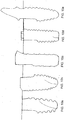
- Figs. 5b, 5c and 5d Several examples of flattened portions of different lengths are shown in Figs. 5b, 5c and 5d , shown alongside a conventional prior art implant in Fig. 5a .
- the topology of the cutaway portion of the implant head may be designed in any one of a variety of ways.
- the smaller periphery portion may be flat or planar, or it can be curved.
- the narrow periphery portion can have the same surface topology as the remainder of the head of the implant, for example, with microthreads or rings for improved adhesion to bone and tissue.
- the smaller periphery head portion may extend to include any part of the implant's length up to its entire length.
- more than one longitudinal cutaway portion may be provided, preferably arranged symmetrically around the body.
- Fig. 6a is an isometric view
- FIG. 7a is a top view of an implant 20 having two cut away portions 22, 24, one opposite the other.
- This type of implant is particularly suitable where the bone ridge is narrow, for example, in the posterior mandible. See, for example, Fig. 8b , showing a cross-section of a posterior mandible 26 with a mandibular nerve canal 27.
- An implant 20 having cut away portions 22, 24 is implanted therein.
- the body of the implant remains of conventional size to retain the mechanical strength of the fixture and of the connection in the bone, but the head has a smaller periphery to provide narrow emergence in the buccal/lingual dimension, which permits minimum bone loss around the implant head and enhanced soft tissue response.
- an enlarged area 28 of bone buccal to the implant head and an enlarged area 29 of bone lingual to the implant head relative to conventional implants are obtained.
- Fig. 6b shows an isometric view
- Fig. 7b shows a top view of an implant 30 having three cutouts 32, 34, 36 equidistant about the longitudinal axis of the implant.
- This type of implant is particularly suitable for use with adjacent implants, particularly in areas where there is low bone volume buccal to the implant heads and between the implants.
- This design is particularly advantageous in the anterior part of upper jaw. See, for example, Fig. 8a , showing an occlusal view of an anterior maxillary bone crest 31 wherein two adjacent teeth 33 have been replaced with implants, after healing of the bone.
- Two implants 30 having cut away portions 32, 34, 36 are implanted in place of the two removed teeth.
- an enlarged area 35 of bone buccal to the implant heads and an enlarged area 37 of bone between the implant heads is provided, relative to conventional cylindrical (not cut away) implants.
- the screw receiving bore for connecting the abutment is not concentric with the longitudinal axis of the implant. This permits the periphery of the implant head to be even smaller than in the symmetrical implant according to the invention described above.
- Fig. 6c shows an isometric view
- Fig. 7c shows a top view of an implant 40 having a single cutout 42, similar to the implant of Fig. 4 , but having an eccentrically disposed screw receiving bore 44 substantially aligned with the longitudinal axis of the implant.
- This design provides an implant having an even larger cutout area than the concentric implant of Fig. 4 , particularly useful in areas where it is desired to provide extra (maximum) bone volume.
- Fig. 6d shows an isometric view
- Fig. 7d shows a top view of an implant 50 having a single cutout 52, similar to the implant of Fig. 6c , having a screw receiving bore 54 non-concentrically disposed relative to the longitudinal axis of the implant.
- the screw receiving bore 54 is not aligned with the longitudinal axis of the implant but rather is formed at an angle thereto, as best seen in Fig. 7d .
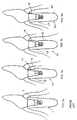
- This design is particularly useful in the anterior region of the upper jaw to ensure extra volume of buccal bone and lingual access to the abutment screw. See, for example, Fig.
- connection and screw hole centers can be positioned more lingually (away from the cutout 52 ) and they can be oriented so as to greatly increase the probability that the abutment screw could be accessed from the lingual aspect 59 of the restoration.
- connection itself (the interface between implant and abutment) could be tilted and in line with the tilted screw or, alternatively, the connection could be kept parallel to the longitudinal axis of the implant with just the screw hole and screw access tilted toward the lingual.
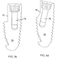
- Figs. 9a, 9b , 9c and 9d provide side sectional illustrations of the various angular possibilities.
- Fig. 9a shows an implant 60 with a cutaway 62 and a screw receiving bore 64 concentrically located and aligned with respect to the longitudinal axis of the implant.
- Fig. 9b shows an implant 65 with a cutaway 66 and a screw receiving bore 68 concentrically located but tilted at an angle with respect to the longitudinal axis of the implant.
- Fig. 9a shows an implant 60 with a cutaway 62 and a screw receiving bore 64 concentrically located and aligned with respect to the longitudinal axis of the implant.
- Fig. 9b shows an implant 65 with a cutaway 66 and a
- FIG. 9c shows an implant 70 with a cutaway 72 and a screw receiving bore 74 eccentrically located but aligned with respect to the longitudinal axis of the implant.
- the cut away portion 72 is enlarged in width, relative to the implant of Fig. 9a .
- Fig. 9d shows an implant 75 with a cutaway 76 and a screw receiving bore 78 eccentrically located and tilted at an angle with respect to the longitudinal axis of the implant.
- the cut away portion 76 can be enlarged in width, relative to the implant of Fig. 9b . It will be appreciated that any of these screw-receiving bore options can be used with any of the designs of implants described above and below and with any of the types of implants desired.
- the particular design of the implant can be selected according to the location in the patient's mouth and the state of the patient's jaw.
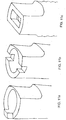
- the modified head design can be applied to all implant designs, regardless of body shape, thread type, length, diameter, connection, surface treatment and material used, or whether it is a bone level, tissue level or one-piece implant. See, for example, Figs. 10a - 10e , each illustrating a different type or design of implant implementing the cutaway portion of the present invention.
- Fig. 10a and Figs. 10b illustrate bone level implants.
- 10c illustrates a tissue level implant.
- Fig. 10d illustrates a bone level implant with an external connection and
- Fig. 10e illustrates a one-piece implant, having a prosthetic integrally formed with the implant body.
- An implant with a single flattened or cut away area will have a single most proper (optimal) orientation (i.e., with the cut away area oriented adjacent the thin bone portion of the jaw).
- This type of implant, with a single cut away portion has a single proper orientation within a full 360 degree of rotational insertion and is better suited for smaller step, tighter thread implants or non-threaded implants.
- this characteristic may be a detriment in the case of threaded implants with a large thread step. While that may not be a problem in the anterior region where sub-bone-level positioning is often carried out, when this is an issue, the heads of the implants could be made with two or three cutouts, as illustrated above, so as to provide two-way or three-way symmetry.
- the implant can be rotated until any one of several cutout portions is disposed facing the problematic area of the jaw, so that additional bone growth will be possible in that area.
- These examples allow for smaller depth variability.
- a two cutout implant head allows two proper positions within every full rotation and a three cutout implant head allows three proper positions within every full rotation.
- connection and the top surface of the implant could be made to suit the particular needs of such implant-abutment pair better than the conventional types of implant-abutment connections.
- FIGs. 11a, 11b and 11c Three exemplary instances of such a connection, having different features for receiving complementary features on the abutment, are depicted in Figs. 11a, 11b and 11c .
- the head defines a protrusion
- Fig. 11b the head defines a flattened portion with notches
- Fig. 11c the head defines a rectangular connection.
- FIG. 12a A further advantage is illustrated schematically in Figs. 12a , showing a prior art implant 80 with a prosthetic unit 82, and an implant 84, illustrated in Fig. 12b .
- Implant 84 has a single cutaway 86 as described above.
- Prior art implant 80 is a tissue level implant where bone and tissue loss may occur. When it does, the metal implant 80 becomes visible. That may be very disturbing, particularly if located in the anterior portion of the mouth.
- the implant 84 permits the prosthetic crown 88 to be extended along part or all of the length of the cut away portion 86. This portion is disposed to be visible in the mouth, so that even if there is some bone or tissue loss, the metal implant 84 will not be visible.
Claims (11)
- Implant dentaire (30) comprenant :un corps d'implant ayant une surface supérieure ;un alésage de réception de vis s'étendant vers le bas depuis la surface supérieure pour accoupler une butée à l'implant ; ettrois parties découpées (32, 34, 36) s'étendant longitudinalement vers le bas depuis la surface supérieure, à égale distance dudit corps et à l'extérieur de la périphérie.
- Implant dentaire selon la revendication 1, dans lequel ledit alésage n'est pas concentrique par rapport à l'axe longitudinal de l'implant.
- Implant dentaire selon la revendication 1 ou la revendication 2, dans lequel ledit alésage est formé selon un certain angle par rapport à un axe longitudinal de l'implant.
- Implant dentaire selon l'une quelconque des revendications précédentes, dans lequel lesdites parties découpées sont effilées.
- Implant dentaire selon l'une quelconque des revendications précédentes, dans lequel lesdites parties découpées se terminent par un épaulement.
- Implant dentaire selon l'une quelconque des revendications précédentes, dans lequel lesdites parties découpées s'étendent sur toute la longueur du corps.
- Implant dentaire selon l'une quelconque des revendications 1 à 6,
ledit corps d'implant comprenant une partie de corps et une partie de tête formée intégralement avec ladite partie de corps, ladite surface supérieure étant définie sur ladite partie de tête ;
ladite partie de corps ayant une périphérie et ladite partie de tête ayant une périphérie non circulaire ; et la périphérie de ladite partie de tête étant plus petite que la périphérie de la partie de corps. - Implant dentaire selon l'une quelconque des revendications précédentes, dans lequel les parties découpées sont aplaties.
- Implant dentaire selon l'une quelconque des revendications 1 à 7, dans lequel les parties découpées sont incurvées.
- Implant dentaire selon l'une quelconque des revendications précédentes, dans lequel la topologie de surface desdites parties découpées comprend des microspires ou des anneaux.
- Implant dentaire selon la revendication 1, ledit implant étant un implant monobloc.
Priority Applications (1)
| Application Number | Priority Date | Filing Date | Title |
|---|---|---|---|
| EP19191143.7A EP3682843B1 (fr) | 2011-06-02 | 2012-06-03 | Implant dentaire |
Applications Claiming Priority (2)
| Application Number | Priority Date | Filing Date | Title |
|---|---|---|---|
| US201161492382P | 2011-06-02 | 2011-06-02 | |
| PCT/IL2012/000218 WO2012164560A1 (fr) | 2011-06-02 | 2012-06-03 | Implant dentaire |
Related Child Applications (1)
| Application Number | Title | Priority Date | Filing Date |
|---|---|---|---|
| EP19191143.7A Division EP3682843B1 (fr) | 2011-06-02 | 2012-06-03 | Implant dentaire |
Publications (3)
| Publication Number | Publication Date |
|---|---|
| EP2713939A1 EP2713939A1 (fr) | 2014-04-09 |
| EP2713939A4 EP2713939A4 (fr) | 2014-12-03 |
| EP2713939B1 true EP2713939B1 (fr) | 2019-08-21 |
Family
ID=47258485
Family Applications (2)
| Application Number | Title | Priority Date | Filing Date |
|---|---|---|---|
| EP19191143.7A Active EP3682843B1 (fr) | 2011-06-02 | 2012-06-03 | Implant dentaire |
| EP12793774.6A Active EP2713939B1 (fr) | 2011-06-02 | 2012-06-03 | Implant dentaire |
Family Applications Before (1)
| Application Number | Title | Priority Date | Filing Date |
|---|---|---|---|
| EP19191143.7A Active EP3682843B1 (fr) | 2011-06-02 | 2012-06-03 | Implant dentaire |
Country Status (11)
| Country | Link |
|---|---|
| US (2) | US10441386B2 (fr) |
| EP (2) | EP3682843B1 (fr) |
| JP (1) | JP6133849B2 (fr) |
| KR (1) | KR102085066B1 (fr) |
| CN (1) | CN103717175A (fr) |
| BR (1) | BR112013030990B1 (fr) |
| ES (2) | ES2948570T3 (fr) |
| IL (1) | IL254322B (fr) |
| PT (2) | PT2713939T (fr) |
| RU (1) | RU2612487C2 (fr) |
| WO (1) | WO2012164560A1 (fr) |
Families Citing this family (34)
| Publication number | Priority date | Publication date | Assignee | Title |
|---|---|---|---|---|
| PL2566413T3 (pl) | 2010-05-05 | 2017-07-31 | Holger Zipprich | Implant stomatologiczny |
| DE102010051176A1 (de) | 2010-11-15 | 2012-05-16 | Urs Brodbeck | Dental-Implantatsystem und Verfahren zur Herstellung eines Dental-Implantatsystems |
| DE102011009906A1 (de) * | 2011-01-31 | 2012-08-02 | Holger Zipprich | Dental- Implantatsystem |
| EP2502600A1 (fr) | 2011-03-21 | 2012-09-26 | Biodenta Swiss AG | Système d'implant dentaire |
| KR102085066B1 (ko) | 2011-06-02 | 2020-03-05 | 엠아이에스 임플란츠 테크놀러지스 리미티드 | 치과용 임플란트 |
| JP6049422B2 (ja) * | 2012-11-27 | 2016-12-21 | 京セラメディカル株式会社 | 歯科インプラント用フィクスチャーおよび歯科インプラント |
| ITLI20130001A1 (it) * | 2013-01-08 | 2014-07-09 | Roberto Malasoma | Impianto dentale osteointegrato contraddistinto da un confine obliquo tra superficie ruvida e liscia |
| TWI583359B (zh) | 2013-02-22 | 2017-05-21 | 巴科納 包瑞斯 Ds | 預防骨質流失之骨內牙植體及基牙 |
| JP2017506122A (ja) * | 2014-02-20 | 2017-03-02 | エムアイエス インプランツ テクノロジーズ リミテッド | 歯科インプラント |
| US11090138B2 (en) | 2014-08-29 | 2021-08-17 | Fereidoun Daftary | Dental implant system and method |
| US10292792B2 (en) * | 2014-08-29 | 2019-05-21 | Nobel Biocare Services Ag | Restoration dental implant and method |
| AU2015311605B2 (en) * | 2014-09-05 | 2020-08-06 | Greg Miller | A dental implant |
| EP3267933A4 (fr) * | 2015-03-11 | 2018-10-17 | Nobel Biocare Services AG | Système d'implant dentaire de restauration et procédé correspondant |
| WO2017129828A1 (fr) * | 2016-01-29 | 2017-08-03 | Nobel Biocare Services Ag | Outil de dentisterie |
| CN108601635B (zh) | 2016-01-29 | 2021-10-08 | 诺贝尔生物服务公司 | 牙种植体、用于牙种植体的插入工具及牙种植体与插入工具的组合 |
| ES2773198T3 (es) | 2016-01-29 | 2020-07-09 | Nobel Biocare Services Ag | Implante dental |
| USD783825S1 (en) | 2016-02-05 | 2017-04-11 | Silvio Franco Emanuelli | Post part for a dental implant |
| USD783822S1 (en) | 2016-02-05 | 2017-04-11 | Silvio Franco Emanuelli | Root part for a dental implant |
| USD783823S1 (en) | 2016-02-05 | 2017-04-11 | Silvio Franco Emanuelli | Post part for a dental implant |
| USD783826S1 (en) | 2016-02-05 | 2017-04-11 | Silvio Franco Emanuelli | Root part for a dental implant |
| USD783824S1 (en) | 2016-02-05 | 2017-04-11 | Silvio Franco Emanuelli | Root part for a dental implant |
| USD785179S1 (en) | 2016-02-05 | 2017-04-25 | Silvio Franco Emanuelli | Post part for a dental implant |
| US10987201B2 (en) * | 2016-02-23 | 2021-04-27 | Paltop Advanced Dental Solutions Ltd. | Dental implant |
| AU2017286777C1 (en) | 2016-06-14 | 2022-04-14 | Southern Implants (Pty) Ltd | Dental implant having reverse-tapered main body for anterior post-extraction sockets |
| IL247473A0 (en) * | 2016-08-24 | 2016-12-29 | Ilia Musheev | Implant with integrated scanning body |
| KR101731542B1 (ko) * | 2016-10-05 | 2017-05-02 | 주식회사 트루어버트먼트코리아 | 임플란트용 픽스쳐 |
| KR101916210B1 (ko) * | 2017-01-13 | 2019-01-30 | 주식회사 덴플렉스 | 치과용 임플란트 |
| IL310554A (en) * | 2018-02-21 | 2024-03-01 | Southern Implants Pty Ltd | Asymmetric dental implant for the cheekbone with a partial microgroove |
| US20210236247A1 (en) * | 2018-05-03 | 2021-08-05 | João Manuel MENDES CARAMÊS | Medical implant and medical implant system for malar process of the maxilla |
| DE102018113237A1 (de) * | 2018-06-04 | 2019-12-05 | TRI Dental Implants Int. AG | Zahnimplantat und Zahnprothese |
| US10987196B2 (en) | 2018-06-27 | 2021-04-27 | Paltop Advanced Dental Solutions Ltd. | Drill guide |
| US11452583B2 (en) * | 2019-01-10 | 2022-09-27 | Paramvir Singh | Dental implant evaluation unit |
| BR202019001133U2 (pt) * | 2019-01-21 | 2020-08-04 | Jjgc Indústria E Comércio De Materiais Dentários S.A. | Implante zigomático com porção rosqueada parcialmente interrompida |
| WO2022132118A1 (fr) * | 2020-12-14 | 2022-06-23 | Борис Михайлович СИМАНОВСКИЙ | Implant dentaire |
Family Cites Families (52)
| Publication number | Priority date | Publication date | Assignee | Title |
|---|---|---|---|---|
| FR2508307A1 (fr) * | 1981-09-16 | 1982-12-31 | Lonca Philippe | Nouveaux implants dentaires et materiel ancillaire pour leur mise en place |
| JP2725194B2 (ja) * | 1988-12-16 | 1998-03-09 | 株式会社アドバンス | 人工歯根 |
| JP2605165B2 (ja) * | 1990-06-13 | 1997-04-30 | 分吉 東 | 人工歯根 |
| WO1992020306A1 (fr) * | 1991-05-24 | 1992-11-26 | Kerry Zang | Dispositif de contention de fracture osseuse |
| US5454811A (en) * | 1993-11-08 | 1995-10-03 | Smith & Nephew Dyonics, Inc. | Cam lock orthopedic fixation screw and method |
| AU6610196A (en) | 1995-08-17 | 1997-03-12 | Institut Straumann Ag | Device for holding small screws using an elastically clamping ring |
| US5785525A (en) * | 1996-05-17 | 1998-07-28 | Weissman; Bernard | Dental implant system |
| US6001100A (en) * | 1997-08-19 | 1999-12-14 | Bionx Implants Oy | Bone block fixation implant |
| US6039568A (en) | 1998-06-02 | 2000-03-21 | Hinds; Kenneth F. | Tooth shaped dental implants |
| IT1313580B1 (it) | 1999-07-26 | 2002-09-09 | Ioannis Corcolis | Dispositivo per impianto dentale. |
| US20060078847A1 (en) * | 2000-09-29 | 2006-04-13 | Kwan Norman H | Dental implant system and additional methods of attachment |
| GB0108551D0 (en) | 2001-04-05 | 2001-05-23 | Osseobiotek Ltd | Implant |
| GB0123804D0 (en) * | 2001-10-04 | 2001-11-21 | Osseobiotek Ltd | Implant |
| US6953463B2 (en) * | 2001-10-12 | 2005-10-11 | Hs West Investments, Llc | Interference screws having increased proximal diameter |
| US6723099B1 (en) * | 2001-11-08 | 2004-04-20 | Biomet, Inc. | Three sided tack for bone fixation |
| US7291012B2 (en) * | 2003-02-27 | 2007-11-06 | Lyren Philip S | Dental implant with porous body |
| IL156033A0 (en) * | 2003-05-21 | 2004-03-28 | Ophir Fromovich Ophir Fromovic | Dental implant |
| DE50309926D1 (de) | 2003-10-16 | 2008-07-10 | Straumann Holding Ag | Verbessertes Übertragungsteil für ein Implantat |
| ITMI20032618A1 (it) * | 2003-12-30 | 2005-06-30 | Ioannis Corcolis | Impianto dentale |
| US20060003290A1 (en) | 2004-07-01 | 2006-01-05 | Niznick Gerald A | Endosseous one-piece screw-type dental implants |
| US7300282B2 (en) * | 2004-07-16 | 2007-11-27 | Sapian Schubert L | Biofunctional dental implant |
| DE202005005421U1 (de) * | 2005-04-05 | 2006-08-10 | Dinkelacker, Wolfgang, Dr.med.dent. | Schraubenförmiges Dentalimplantat |
| ES2351277T3 (es) | 2005-08-03 | 2011-02-02 | Straumann Holding Ag | Elemento de sujeción para un implante dental. |
| AT502881B1 (de) * | 2005-10-05 | 2007-08-15 | Pirker Wolfgang Ddr | Zahnimplantat |
| EP1882458A1 (fr) * | 2006-07-27 | 2008-01-30 | Straumann Holding AG | Implant dentaire |
| DE202007018746U1 (de) | 2007-01-12 | 2009-03-19 | Zl Microdent-Attachment Gmbh & Co. Kg | Schraubwerkzeug und Halteelement für ein Schraubwerkzeug |
| US7806693B2 (en) * | 2007-04-23 | 2010-10-05 | Nobel Biocare Services Ag | Dental implant |
| WO2008157137A1 (fr) * | 2007-06-14 | 2008-12-24 | Southern Implants, Inc. | Système d'implant dentaire destiné à être utilisé avec des prothèses non alignées coaxialement |
| WO2008157138A2 (fr) * | 2007-06-14 | 2008-12-24 | Southern Implants, Inc. | Implant dentaire pour montage à point d'appui asymétrique |
| UA27037U (en) * | 2007-06-19 | 2007-10-10 | Dental implant | |
| WO2009015103A1 (fr) * | 2007-07-20 | 2009-01-29 | Cochlear Americas | Appareil d'accouplement pour un dispositif auditif ancré sur un os |
| US8066511B2 (en) * | 2008-03-18 | 2011-11-29 | Woehrle Peter | Asymmetrical dental implant |
| KR100931996B1 (ko) * | 2008-05-19 | 2009-12-15 | 오스템임플란트 주식회사 | 치과용 임플란트 픽스쳐 |
| DE102009060656A1 (de) | 2008-12-22 | 2010-08-12 | Neumeyer, Stefan, Dr. | Spreizelement zum Spreizen von Knochenstrukturen |
| DE102008063397B4 (de) * | 2008-12-30 | 2019-02-21 | Holger Zipprich | Dentalimplantatsschraube |
| USD616097S1 (en) * | 2009-09-15 | 2010-05-18 | 3M Innovative Properties Company | Dental implant abutment |
| JP5814255B2 (ja) * | 2009-12-11 | 2015-11-17 | ヴェルチェロッティ,トマソ | 歯科用骨内インプラント |
| EP2444023A1 (fr) | 2010-10-20 | 2012-04-25 | Astra Tech AB | Composant dentaire, appareil dentaire et ensemble formant implant dentaire |
| KR101050236B1 (ko) | 2010-12-20 | 2011-07-19 | 정효경 | 치공구 드라이버 |
| EP2510899A1 (fr) * | 2011-04-14 | 2012-10-17 | Astra Tech AB | Dispositif de fixation |
| KR102085066B1 (ko) | 2011-06-02 | 2020-03-05 | 엠아이에스 임플란츠 테크놀러지스 리미티드 | 치과용 임플란트 |
| WO2012173577A1 (fr) | 2011-06-13 | 2012-12-20 | Haydar Imad | Implant dentaire à section ovale |
| EP2570097A1 (fr) | 2011-09-14 | 2013-03-20 | Dentsply IH AB | Composant dentaire, fixation dentaire et implant dentaire |
| EP2570095A1 (fr) | 2011-09-14 | 2013-03-20 | Dentsply IH AB | Composant dentaire et implant dentaire |
| JP5512626B2 (ja) | 2011-10-03 | 2014-06-04 | ワイ.エス.ハング ウィリアム | 歯科インプラント |
| US20140030674A1 (en) | 2012-01-27 | 2014-01-30 | Hao Nguyen | Prefabricated immediate no-drill dental implant |
| US9119688B2 (en) | 2012-03-01 | 2015-09-01 | Straumann Holding Ag | Holding device for dental implant |
| KR101457011B1 (ko) | 2012-04-06 | 2014-11-04 | 오상훈 | 치과용 임플란트 고정구 천공 가이드 장치 및 이를 이용한 천공 방법 |
| JP5813080B2 (ja) * | 2013-12-11 | 2015-11-17 | 本田技研工業株式会社 | 背負い式動力噴霧機 |
| DE102014118723A1 (de) | 2013-12-17 | 2015-06-18 | Epiphanostics GmbH | Enossales Einzelzahnimplantat |
| JP2017506122A (ja) | 2014-02-20 | 2017-03-02 | エムアイエス インプランツ テクノロジーズ リミテッド | 歯科インプラント |
| KR101594095B1 (ko) * | 2014-03-05 | 2016-02-15 | 주식회사 이비아이 | 혈액 수용이 용이한 치과용 임플란트 픽스쳐 |
-
2012
- 2012-06-03 KR KR1020137035023A patent/KR102085066B1/ko active IP Right Grant
- 2012-06-03 RU RU2013158082A patent/RU2612487C2/ru active
- 2012-06-03 JP JP2014513308A patent/JP6133849B2/ja active Active
- 2012-06-03 CN CN201280037636.2A patent/CN103717175A/zh active Pending
- 2012-06-03 ES ES19191143T patent/ES2948570T3/es active Active
- 2012-06-03 ES ES12793774T patent/ES2753967T3/es active Active
- 2012-06-03 EP EP19191143.7A patent/EP3682843B1/fr active Active
- 2012-06-03 PT PT127937746T patent/PT2713939T/pt unknown
- 2012-06-03 US US14/123,289 patent/US10441386B2/en active Active
- 2012-06-03 WO PCT/IL2012/000218 patent/WO2012164560A1/fr active Application Filing
- 2012-06-03 PT PT191911437T patent/PT3682843T/pt unknown
- 2012-06-03 EP EP12793774.6A patent/EP2713939B1/fr active Active
- 2012-06-03 BR BR112013030990-3A patent/BR112013030990B1/pt active IP Right Grant
-
2017
- 2017-09-04 IL IL254322A patent/IL254322B/en unknown
-
2019
- 2019-09-19 US US16/575,467 patent/US20200078146A1/en active Pending
Non-Patent Citations (1)
| Title |
|---|
| None * |
Also Published As
| Publication number | Publication date |
|---|---|
| EP2713939A1 (fr) | 2014-04-09 |
| RU2013158082A (ru) | 2015-07-20 |
| WO2012164560A1 (fr) | 2012-12-06 |
| JP2014516721A (ja) | 2014-07-17 |
| ES2753967T3 (es) | 2020-04-15 |
| IL254322B (en) | 2021-12-01 |
| ES2948570T3 (es) | 2023-09-14 |
| PT2713939T (pt) | 2019-11-29 |
| JP6133849B2 (ja) | 2017-05-24 |
| KR102085066B1 (ko) | 2020-03-05 |
| US20200078146A1 (en) | 2020-03-12 |
| BR112013030990A2 (pt) | 2016-11-29 |
| RU2612487C2 (ru) | 2017-03-09 |
| US20140106305A1 (en) | 2014-04-17 |
| EP3682843A1 (fr) | 2020-07-22 |
| PT3682843T (pt) | 2023-06-22 |
| KR20150035351A (ko) | 2015-04-06 |
| EP2713939A4 (fr) | 2014-12-03 |
| IL254322A0 (en) | 2017-11-30 |
| EP3682843B1 (fr) | 2023-04-05 |
| CN103717175A (zh) | 2014-04-09 |
| BR112013030990B1 (pt) | 2020-12-22 |
| US10441386B2 (en) | 2019-10-15 |
Similar Documents
| Publication | Publication Date | Title |
|---|---|---|
| EP2713939B1 (fr) | Implant dentaire | |
| JP4747240B2 (ja) | 骨に使用するための固定要素 | |
| JP5275460B2 (ja) | 医療用インプラントおよび植設方法 | |
| EP1624826B1 (fr) | Implant squelettique à condensation facilitant l'introduction | |
| JP6259822B2 (ja) | アバットメントシステム及び歯科方法 | |
| CA2766927C (fr) | Implant dentaire asymetrique modifie | |
| KR20110033853A (ko) | 분리형 치과 임플란트의 개선된 고정체 | |
| JP2007502648A (ja) | 歯科用インプラント | |
| JP2008511350A (ja) | 歯科インプラントシステム、およびインプラントシステムの埋込みならびに植立のための方法 | |
| KR100807150B1 (ko) | 오버덴쳐 시술용 임플란트 | |
| EP3453358B1 (fr) | Implant de niveau tissulaire amélioré | |
| JP5259557B2 (ja) | 歯科インプラント | |
| US20140030674A1 (en) | Prefabricated immediate no-drill dental implant | |
| CA2959587C (fr) | Systeme d'implant dentaire de restauration et procede correspondant | |
| CN105101906B (zh) | 具有带一个或多个外圈的安装元件的单件式或多件式种植系统 | |
| US20100311014A1 (en) | Dental implant | |
| KR200392276Y1 (ko) | 치과용 임플란트 | |
| KR200392241Y1 (ko) | 치과용 임시 임플란트 | |
| KR20210071682A (ko) | 어버트먼트 조립체 및 그 조립 방법 | |
| IL229758A (en) | Dental implant | |
| WO2011056323A2 (fr) | Implant pouvant être monté de manière variable avec une alvéole dentaire en escalier |
Legal Events
| Date | Code | Title | Description |
|---|---|---|---|
| PUAI | Public reference made under article 153(3) epc to a published international application that has entered the european phase |
Free format text: ORIGINAL CODE: 0009012 |
|
| 17P | Request for examination filed |
Effective date: 20131218 |
|
| AK | Designated contracting states |
Kind code of ref document: A1 Designated state(s): AL AT BE BG CH CY CZ DE DK EE ES FI FR GB GR HR HU IE IS IT LI LT LU LV MC MK MT NL NO PL PT RO RS SE SI SK SM TR |
|
| DAX | Request for extension of the european patent (deleted) | ||
| A4 | Supplementary search report drawn up and despatched |
Effective date: 20141104 |
|
| RIC1 | Information provided on ipc code assigned before grant |
Ipc: A61C 8/00 20060101AFI20141029BHEP |
|
| STAA | Information on the status of an ep patent application or granted ep patent |
Free format text: STATUS: EXAMINATION IS IN PROGRESS |
|
| 17Q | First examination report despatched |
Effective date: 20170918 |
|
| REG | Reference to a national code |
Ref country code: DE Ref legal event code: R079 Ref document number: 602012063184 Country of ref document: DE Free format text: PREVIOUS MAIN CLASS: A61C0008000000 Ipc: A61C0008020000 |
|
| GRAP | Despatch of communication of intention to grant a patent |
Free format text: ORIGINAL CODE: EPIDOSNIGR1 |
|
| STAA | Information on the status of an ep patent application or granted ep patent |
Free format text: STATUS: GRANT OF PATENT IS INTENDED |
|
| RIC1 | Information provided on ipc code assigned before grant |
Ipc: A61C 8/02 20060101AFI20190314BHEP Ipc: A61C 8/00 20060101ALI20190314BHEP |
|
| INTG | Intention to grant announced |
Effective date: 20190416 |
|
| GRAJ | Information related to disapproval of communication of intention to grant by the applicant or resumption of examination proceedings by the epo deleted |
Free format text: ORIGINAL CODE: EPIDOSDIGR1 |
|
| STAA | Information on the status of an ep patent application or granted ep patent |
Free format text: STATUS: EXAMINATION IS IN PROGRESS |
|
| GRAR | Information related to intention to grant a patent recorded |
Free format text: ORIGINAL CODE: EPIDOSNIGR71 |
|
| GRAS | Grant fee paid |
Free format text: ORIGINAL CODE: EPIDOSNIGR3 |
|
| STAA | Information on the status of an ep patent application or granted ep patent |
Free format text: STATUS: GRANT OF PATENT IS INTENDED |
|
| GRAA | (expected) grant |
Free format text: ORIGINAL CODE: 0009210 |
|
| STAA | Information on the status of an ep patent application or granted ep patent |
Free format text: STATUS: THE PATENT HAS BEEN GRANTED |
|
| INTC | Intention to grant announced (deleted) | ||
| INTG | Intention to grant announced |
Effective date: 20190710 |
|
| AK | Designated contracting states |
Kind code of ref document: B1 Designated state(s): AL AT BE BG CH CY CZ DE DK EE ES FI FR GB GR HR HU IE IS IT LI LT LU LV MC MK MT NL NO PL PT RO RS SE SI SK SM TR |
|
| REG | Reference to a national code |
Ref country code: GB Ref legal event code: FG4D |
|
| REG | Reference to a national code |
Ref country code: CH Ref legal event code: EP |
|
| REG | Reference to a national code |
Ref country code: DE Ref legal event code: R096 Ref document number: 602012063184 Country of ref document: DE |
|
| REG | Reference to a national code |
Ref country code: AT Ref legal event code: REF Ref document number: 1168823 Country of ref document: AT Kind code of ref document: T Effective date: 20190915 |
|
| REG | Reference to a national code |
Ref country code: IE Ref legal event code: FG4D |
|
| REG | Reference to a national code |
Ref country code: CH Ref legal event code: NV Representative=s name: DENNEMEYER AG, CH |
|
| REG | Reference to a national code |
Ref country code: SE Ref legal event code: TRGR |
|
| REG | Reference to a national code |
Ref country code: RO Ref legal event code: EPE |
|
| REG | Reference to a national code |
Ref country code: PT Ref legal event code: SC4A Ref document number: 2713939 Country of ref document: PT Date of ref document: 20191129 Kind code of ref document: T Free format text: AVAILABILITY OF NATIONAL TRANSLATION Effective date: 20191121 |
|
| REG | Reference to a national code |
Ref country code: LT Ref legal event code: MG4D |
|
| REG | Reference to a national code |
Ref country code: NL Ref legal event code: MP Effective date: 20190821 |
|
| PG25 | Lapsed in a contracting state [announced via postgrant information from national office to epo] |
Ref country code: NO Free format text: LAPSE BECAUSE OF FAILURE TO SUBMIT A TRANSLATION OF THE DESCRIPTION OR TO PAY THE FEE WITHIN THE PRESCRIBED TIME-LIMIT Effective date: 20191121 Ref country code: FI Free format text: LAPSE BECAUSE OF FAILURE TO SUBMIT A TRANSLATION OF THE DESCRIPTION OR TO PAY THE FEE WITHIN THE PRESCRIBED TIME-LIMIT Effective date: 20190821 Ref country code: HR Free format text: LAPSE BECAUSE OF FAILURE TO SUBMIT A TRANSLATION OF THE DESCRIPTION OR TO PAY THE FEE WITHIN THE PRESCRIBED TIME-LIMIT Effective date: 20190821 Ref country code: NL Free format text: LAPSE BECAUSE OF FAILURE TO SUBMIT A TRANSLATION OF THE DESCRIPTION OR TO PAY THE FEE WITHIN THE PRESCRIBED TIME-LIMIT Effective date: 20190821 Ref country code: BG Free format text: LAPSE BECAUSE OF FAILURE TO SUBMIT A TRANSLATION OF THE DESCRIPTION OR TO PAY THE FEE WITHIN THE PRESCRIBED TIME-LIMIT Effective date: 20191121 Ref country code: LT Free format text: LAPSE BECAUSE OF FAILURE TO SUBMIT A TRANSLATION OF THE DESCRIPTION OR TO PAY THE FEE WITHIN THE PRESCRIBED TIME-LIMIT Effective date: 20190821 |
|
| PG25 | Lapsed in a contracting state [announced via postgrant information from national office to epo] |
Ref country code: AL Free format text: LAPSE BECAUSE OF FAILURE TO SUBMIT A TRANSLATION OF THE DESCRIPTION OR TO PAY THE FEE WITHIN THE PRESCRIBED TIME-LIMIT Effective date: 20190821 Ref country code: GR Free format text: LAPSE BECAUSE OF FAILURE TO SUBMIT A TRANSLATION OF THE DESCRIPTION OR TO PAY THE FEE WITHIN THE PRESCRIBED TIME-LIMIT Effective date: 20191122 Ref country code: LV Free format text: LAPSE BECAUSE OF FAILURE TO SUBMIT A TRANSLATION OF THE DESCRIPTION OR TO PAY THE FEE WITHIN THE PRESCRIBED TIME-LIMIT Effective date: 20190821 Ref country code: RS Free format text: LAPSE BECAUSE OF FAILURE TO SUBMIT A TRANSLATION OF THE DESCRIPTION OR TO PAY THE FEE WITHIN THE PRESCRIBED TIME-LIMIT Effective date: 20190821 Ref country code: IS Free format text: LAPSE BECAUSE OF FAILURE TO SUBMIT A TRANSLATION OF THE DESCRIPTION OR TO PAY THE FEE WITHIN THE PRESCRIBED TIME-LIMIT Effective date: 20191221 |
|
| REG | Reference to a national code |
Ref country code: AT Ref legal event code: MK05 Ref document number: 1168823 Country of ref document: AT Kind code of ref document: T Effective date: 20190821 |
|
| PG25 | Lapsed in a contracting state [announced via postgrant information from national office to epo] |
Ref country code: TR Free format text: LAPSE BECAUSE OF FAILURE TO SUBMIT A TRANSLATION OF THE DESCRIPTION OR TO PAY THE FEE WITHIN THE PRESCRIBED TIME-LIMIT Effective date: 20190821 |
|
| REG | Reference to a national code |
Ref country code: ES Ref legal event code: FG2A Ref document number: 2753967 Country of ref document: ES Kind code of ref document: T3 Effective date: 20200415 |
|
| PG25 | Lapsed in a contracting state [announced via postgrant information from national office to epo] |
Ref country code: PL Free format text: LAPSE BECAUSE OF FAILURE TO SUBMIT A TRANSLATION OF THE DESCRIPTION OR TO PAY THE FEE WITHIN THE PRESCRIBED TIME-LIMIT Effective date: 20190821 Ref country code: DK Free format text: LAPSE BECAUSE OF FAILURE TO SUBMIT A TRANSLATION OF THE DESCRIPTION OR TO PAY THE FEE WITHIN THE PRESCRIBED TIME-LIMIT Effective date: 20190821 Ref country code: AT Free format text: LAPSE BECAUSE OF FAILURE TO SUBMIT A TRANSLATION OF THE DESCRIPTION OR TO PAY THE FEE WITHIN THE PRESCRIBED TIME-LIMIT Effective date: 20190821 Ref country code: EE Free format text: LAPSE BECAUSE OF FAILURE TO SUBMIT A TRANSLATION OF THE DESCRIPTION OR TO PAY THE FEE WITHIN THE PRESCRIBED TIME-LIMIT Effective date: 20190821 |
|
| PG25 | Lapsed in a contracting state [announced via postgrant information from national office to epo] |
Ref country code: CZ Free format text: LAPSE BECAUSE OF FAILURE TO SUBMIT A TRANSLATION OF THE DESCRIPTION OR TO PAY THE FEE WITHIN THE PRESCRIBED TIME-LIMIT Effective date: 20190821 Ref country code: SM Free format text: LAPSE BECAUSE OF FAILURE TO SUBMIT A TRANSLATION OF THE DESCRIPTION OR TO PAY THE FEE WITHIN THE PRESCRIBED TIME-LIMIT Effective date: 20190821 Ref country code: SK Free format text: LAPSE BECAUSE OF FAILURE TO SUBMIT A TRANSLATION OF THE DESCRIPTION OR TO PAY THE FEE WITHIN THE PRESCRIBED TIME-LIMIT Effective date: 20190821 Ref country code: IS Free format text: LAPSE BECAUSE OF FAILURE TO SUBMIT A TRANSLATION OF THE DESCRIPTION OR TO PAY THE FEE WITHIN THE PRESCRIBED TIME-LIMIT Effective date: 20200224 |
|
| REG | Reference to a national code |
Ref country code: DE Ref legal event code: R097 Ref document number: 602012063184 Country of ref document: DE |
|
| PLBE | No opposition filed within time limit |
Free format text: ORIGINAL CODE: 0009261 |
|
| STAA | Information on the status of an ep patent application or granted ep patent |
Free format text: STATUS: NO OPPOSITION FILED WITHIN TIME LIMIT |
|
| PG2D | Information on lapse in contracting state deleted |
Ref country code: IS |
|
| 26N | No opposition filed |
Effective date: 20200603 |
|
| PG25 | Lapsed in a contracting state [announced via postgrant information from national office to epo] |
Ref country code: SI Free format text: LAPSE BECAUSE OF FAILURE TO SUBMIT A TRANSLATION OF THE DESCRIPTION OR TO PAY THE FEE WITHIN THE PRESCRIBED TIME-LIMIT Effective date: 20190821 |
|
| PG25 | Lapsed in a contracting state [announced via postgrant information from national office to epo] |
Ref country code: MC Free format text: LAPSE BECAUSE OF FAILURE TO SUBMIT A TRANSLATION OF THE DESCRIPTION OR TO PAY THE FEE WITHIN THE PRESCRIBED TIME-LIMIT Effective date: 20190821 |
|
| PG25 | Lapsed in a contracting state [announced via postgrant information from national office to epo] |
Ref country code: LU Free format text: LAPSE BECAUSE OF NON-PAYMENT OF DUE FEES Effective date: 20200603 |
|
| PG25 | Lapsed in a contracting state [announced via postgrant information from national office to epo] |
Ref country code: IE Free format text: LAPSE BECAUSE OF NON-PAYMENT OF DUE FEES Effective date: 20200603 |
|
| PG25 | Lapsed in a contracting state [announced via postgrant information from national office to epo] |
Ref country code: MT Free format text: LAPSE BECAUSE OF FAILURE TO SUBMIT A TRANSLATION OF THE DESCRIPTION OR TO PAY THE FEE WITHIN THE PRESCRIBED TIME-LIMIT Effective date: 20190821 Ref country code: CY Free format text: LAPSE BECAUSE OF FAILURE TO SUBMIT A TRANSLATION OF THE DESCRIPTION OR TO PAY THE FEE WITHIN THE PRESCRIBED TIME-LIMIT Effective date: 20190821 |
|
| PG25 | Lapsed in a contracting state [announced via postgrant information from national office to epo] |
Ref country code: MK Free format text: LAPSE BECAUSE OF FAILURE TO SUBMIT A TRANSLATION OF THE DESCRIPTION OR TO PAY THE FEE WITHIN THE PRESCRIBED TIME-LIMIT Effective date: 20190821 |
|
| P01 | Opt-out of the competence of the unified patent court (upc) registered |
Effective date: 20230509 |
|
| PGFP | Annual fee paid to national office [announced via postgrant information from national office to epo] |
Ref country code: RO Payment date: 20230529 Year of fee payment: 12 Ref country code: PT Payment date: 20230602 Year of fee payment: 12 Ref country code: IT Payment date: 20230510 Year of fee payment: 12 Ref country code: FR Payment date: 20230510 Year of fee payment: 12 Ref country code: DE Payment date: 20230502 Year of fee payment: 12 |
|
| PGFP | Annual fee paid to national office [announced via postgrant information from national office to epo] |
Ref country code: SE Payment date: 20230510 Year of fee payment: 12 |
|
| PGFP | Annual fee paid to national office [announced via postgrant information from national office to epo] |
Ref country code: BE Payment date: 20230517 Year of fee payment: 12 |
|
| PGFP | Annual fee paid to national office [announced via postgrant information from national office to epo] |
Ref country code: GB Payment date: 20230504 Year of fee payment: 12 Ref country code: ES Payment date: 20230707 Year of fee payment: 12 Ref country code: CH Payment date: 20230702 Year of fee payment: 12 |