EP2710255B1 - Centrale hydraulique comportant un ensemble à grille d'admission d'eau dans la turbine agence pour evacuer des débris flottants arrétés par la grille. - Google Patents
Centrale hydraulique comportant un ensemble à grille d'admission d'eau dans la turbine agence pour evacuer des débris flottants arrétés par la grille. Download PDFInfo
- Publication number
- EP2710255B1 EP2710255B1 EP12722775.9A EP12722775A EP2710255B1 EP 2710255 B1 EP2710255 B1 EP 2710255B1 EP 12722775 A EP12722775 A EP 12722775A EP 2710255 B1 EP2710255 B1 EP 2710255B1
- Authority
- EP
- European Patent Office
- Prior art keywords
- grating
- flap valve
- assembly
- turbine unit
- power plant
- Prior art date
- Legal status (The legal status is an assumption and is not a legal conclusion. Google has not performed a legal analysis and makes no representation as to the accuracy of the status listed.)
- Not-in-force
Links
- XLYOFNOQVPJJNP-UHFFFAOYSA-N water Substances O XLYOFNOQVPJJNP-UHFFFAOYSA-N 0.000 title claims description 76
- 238000011144 upstream manufacturing Methods 0.000 claims description 54
- 238000006073 displacement reaction Methods 0.000 claims description 20
- 239000007787 solid Substances 0.000 claims description 6
- 238000000034 method Methods 0.000 claims description 5
- 230000005611 electricity Effects 0.000 claims description 3
- 230000014759 maintenance of location Effects 0.000 claims 10
- 238000000638 solvent extraction Methods 0.000 claims 2
- 230000001419 dependent effect Effects 0.000 claims 1
- 238000007599 discharging Methods 0.000 claims 1
- 241000940835 Pales Species 0.000 description 13
- 206010033546 Pallor Diseases 0.000 description 13
- 230000004907 flux Effects 0.000 description 9
- 238000005192 partition Methods 0.000 description 6
- 230000000712 assembly Effects 0.000 description 4
- 238000000429 assembly Methods 0.000 description 4
- 241001465754 Metazoa Species 0.000 description 2
- 238000004140 cleaning Methods 0.000 description 2
- 230000009977 dual effect Effects 0.000 description 2
- 238000011010 flushing procedure Methods 0.000 description 2
- 239000010813 municipal solid waste Substances 0.000 description 2
- 241001080024 Telles Species 0.000 description 1
- 238000004891 communication Methods 0.000 description 1
- 238000001514 detection method Methods 0.000 description 1
- 230000009189 diving Effects 0.000 description 1
- 230000000694 effects Effects 0.000 description 1
- 230000001788 irregular Effects 0.000 description 1
- 238000004519 manufacturing process Methods 0.000 description 1
- 238000004806 packaging method and process Methods 0.000 description 1
- 238000005381 potential energy Methods 0.000 description 1
- ZJFJVRPLNAMIKH-UHFFFAOYSA-N pseudo-u Chemical compound O=C1NC(=O)C(C)=CN1C1OC(COP(O)(=S)OC2C(OC(C2)N2C(N=C(N)C=C2)=O)COP(O)(=S)OC2C(OC(C2)N2C(N=C(N)C=C2)=O)COP(O)(=S)OC2C(OC(C2)N2C(N=C(N)C=C2)=O)COP(O)(=S)OC2C(OC(C2)N2C(NC(=O)C(C)=C2)=O)COP(O)(=S)OC2C(OC(C2)N2C3=C(C(NC(N)=N3)=O)N=C2)COP(O)(=S)OC2C(OC(C2)N2C3=NC=NC(N)=C3N=C2)COP(O)(=S)OC2C(OC(C2)N2C3=NC=NC(N)=C3N=C2)COP(O)(=S)OC2C(OC(C2)N2C(N=C(N)C=C2)=O)COP(O)(=S)OC2C(OC(C2)N2C(NC(=O)C(C)=C2)=O)COP(O)(=S)OC2C(OC(C2)N2C(NC(=O)C(C)=C2)=O)COP(O)(=S)OC2C(OC(C2)N2C3=C(C(NC(N)=N3)=O)N=C2)COP(O)(=S)OC2C(OC(C2)N2C3=C(C(NC(N)=N3)=O)N=C2)COP(O)(=S)OC2C(OC(C2)N2C3=C(C(NC(N)=N3)=O)N=C2)COP(O)(=S)OC2C(OC(C2)N2C3=NC=NC(N)=C3N=C2)CO)C(O)C1 ZJFJVRPLNAMIKH-UHFFFAOYSA-N 0.000 description 1
Images
Classifications
-
- E—FIXED CONSTRUCTIONS
- E02—HYDRAULIC ENGINEERING; FOUNDATIONS; SOIL SHIFTING
- E02B—HYDRAULIC ENGINEERING
- E02B5/00—Artificial water canals, e.g. irrigation canals
- E02B5/08—Details, e.g. gates, screens
- E02B5/085—Arresting devices for waterborne materials, e.g. gratings
-
- B—PERFORMING OPERATIONS; TRANSPORTING
- B01—PHYSICAL OR CHEMICAL PROCESSES OR APPARATUS IN GENERAL
- B01D—SEPARATION
- B01D29/00—Filters with filtering elements stationary during filtration, e.g. pressure or suction filters, not covered by groups B01D24/00 - B01D27/00; Filtering elements therefor
- B01D29/96—Filters with filtering elements stationary during filtration, e.g. pressure or suction filters, not covered by groups B01D24/00 - B01D27/00; Filtering elements therefor in which the filtering elements are moved between filtering operations; Particular measures for removing or replacing the filtering elements; Transport systems for filters
- B01D29/965—Device for changing the inclination of the filtering element
-
- B—PERFORMING OPERATIONS; TRANSPORTING
- B01—PHYSICAL OR CHEMICAL PROCESSES OR APPARATUS IN GENERAL
- B01D—SEPARATION
- B01D35/00—Filtering devices having features not specifically covered by groups B01D24/00 - B01D33/00, or for applications not specifically covered by groups B01D24/00 - B01D33/00; Auxiliary devices for filtration; Filter housing constructions
- B01D35/02—Filters adapted for location in special places, e.g. pipe-lines, pumps, stop-cocks
-
- E—FIXED CONSTRUCTIONS
- E02—HYDRAULIC ENGINEERING; FOUNDATIONS; SOIL SHIFTING
- E02B—HYDRAULIC ENGINEERING
- E02B8/00—Details of barrages or weirs ; Energy dissipating devices carried by lock or dry-dock gates
- E02B8/02—Sediment base gates; Sand sluices; Structures for retaining arresting waterborne material
- E02B8/023—Arresting devices for waterborne materials
-
- F—MECHANICAL ENGINEERING; LIGHTING; HEATING; WEAPONS; BLASTING
- F03—MACHINES OR ENGINES FOR LIQUIDS; WIND, SPRING, OR WEIGHT MOTORS; PRODUCING MECHANICAL POWER OR A REACTIVE PROPULSIVE THRUST, NOT OTHERWISE PROVIDED FOR
- F03B—MACHINES OR ENGINES FOR LIQUIDS
- F03B11/00—Parts or details not provided for in, or of interest apart from, the preceding groups, e.g. wear-protection couplings, between turbine and generator
- F03B11/08—Parts or details not provided for in, or of interest apart from, the preceding groups, e.g. wear-protection couplings, between turbine and generator for removing foreign matter, e.g. mud
-
- F—MECHANICAL ENGINEERING; LIGHTING; HEATING; WEAPONS; BLASTING
- F03—MACHINES OR ENGINES FOR LIQUIDS; WIND, SPRING, OR WEIGHT MOTORS; PRODUCING MECHANICAL POWER OR A REACTIVE PROPULSIVE THRUST, NOT OTHERWISE PROVIDED FOR
- F03B—MACHINES OR ENGINES FOR LIQUIDS
- F03B13/00—Adaptations of machines or engines for special use; Combinations of machines or engines with driving or driven apparatus; Power stations or aggregates
- F03B13/08—Machine or engine aggregates in dams or the like; Conduits therefor, e.g. diffusors
-
- F—MECHANICAL ENGINEERING; LIGHTING; HEATING; WEAPONS; BLASTING
- F03—MACHINES OR ENGINES FOR LIQUIDS; WIND, SPRING, OR WEIGHT MOTORS; PRODUCING MECHANICAL POWER OR A REACTIVE PROPULSIVE THRUST, NOT OTHERWISE PROVIDED FOR
- F03B—MACHINES OR ENGINES FOR LIQUIDS
- F03B3/00—Machines or engines of reaction type; Parts or details peculiar thereto
- F03B3/04—Machines or engines of reaction type; Parts or details peculiar thereto with substantially axial flow throughout rotors, e.g. propeller turbines
-
- F—MECHANICAL ENGINEERING; LIGHTING; HEATING; WEAPONS; BLASTING
- F03—MACHINES OR ENGINES FOR LIQUIDS; WIND, SPRING, OR WEIGHT MOTORS; PRODUCING MECHANICAL POWER OR A REACTIVE PROPULSIVE THRUST, NOT OTHERWISE PROVIDED FOR
- F03B—MACHINES OR ENGINES FOR LIQUIDS
- F03B3/00—Machines or engines of reaction type; Parts or details peculiar thereto
- F03B3/12—Blades; Blade-carrying rotors
- F03B3/14—Rotors having adjustable blades
-
- E—FIXED CONSTRUCTIONS
- E02—HYDRAULIC ENGINEERING; FOUNDATIONS; SOIL SHIFTING
- E02B—HYDRAULIC ENGINEERING
- E02B9/00—Water-power plants; Layout, construction or equipment, methods of, or apparatus for, making same
- E02B9/02—Water-ways
- E02B9/04—Free-flow canals or flumes; Intakes
-
- Y—GENERAL TAGGING OF NEW TECHNOLOGICAL DEVELOPMENTS; GENERAL TAGGING OF CROSS-SECTIONAL TECHNOLOGIES SPANNING OVER SEVERAL SECTIONS OF THE IPC; TECHNICAL SUBJECTS COVERED BY FORMER USPC CROSS-REFERENCE ART COLLECTIONS [XRACs] AND DIGESTS
- Y02—TECHNOLOGIES OR APPLICATIONS FOR MITIGATION OR ADAPTATION AGAINST CLIMATE CHANGE
- Y02E—REDUCTION OF GREENHOUSE GAS [GHG] EMISSIONS, RELATED TO ENERGY GENERATION, TRANSMISSION OR DISTRIBUTION
- Y02E10/00—Energy generation through renewable energy sources
- Y02E10/20—Hydro energy
Definitions
- the invention relates to the protection of turbines of hydraulic power plants installed on water supply works, against the debris conveyed by the water which, if they crossed the impeller blades of the turbines, would be likely to deteriorate them or disrupt their operation.
- the invention relates more specifically to the evacuation of floating debris stopped by the grids of the grid assemblies which are provided with such hydraulic power plants without these debris passing through the impeller wheels of the turbine assemblies.
- the object of the invention is first and foremost a hydraulic power plant for a water supply structure such as including a flow channel of a flow of water limited by a structure having a base and two walls forming walls. comprising, functionally associated, downstream, a turbine assembly as just defined, and, upstream, an intake grid assembly of the water flow.
- the subject of the invention is, secondly, a grid assembly intended to be functionally associated with a turbine assembly, to form such a hydraulic power station.
- the subject of the invention is a method of implementing such a hydraulic unit in order to evacuate floating debris stopped by the grid.
- the document FR-A-2862723 describes a turbine assembly for a hydraulic power plant of the type which is the subject of the invention.
- a hydraulic power plant is intended to equip a stream at a very low drop of less than 10 meters, and preferably 1 to 5 meters. It comprises a paddle wheel, the ratio between the kinetic energy of the water flow at the outlet of the wheel and the potential energy of the fall being less than 20%.
- the turbine assembly is equipped with the upstream side and opposite the opening of the housing of the paddle wheel of a water flow intake grille suitable and intended to stop by its upstream side of the debris conveyed by the water flow of a size greater than that of the passages it comprises.
- the turbine assembly is equipped with the upstream side which is the grid in question, a screen with rotating arms associated with the gate having the function of unclog debris accumulating on it on the upstream side.
- an inlet pre-grid of suitable water flow and intended to be mounted with a position erected in and through the channel of the water supply structure. water, upstream of the turbine assembly.
- This pre-grid has passages of a size larger than the size of the passages of the grid equipping the turbine assembly.
- the pre-grid is adapted and intended to stop debris conveyed by the flow of large water, while the grid equipping the turbine assembly is adapted and intended to stop debris of smaller size.
- the pre-grid and the grid therefore combine their effects.
- Such an intake pre-grid is part of an intake grid assembly of the water flow which, in addition to the pre-grid, includes means for associating the pre-grid with the supporting structure of the assembly. turbine or, more frequently, to the structure of the water supply structure.
- the document FR-A-2835548 discloses an articulated linear grating unblocking module, comprising a scraper carried at the end of a movable arm, which makes this device unsuitable, as previously indicated.
- the document US 1,586,754 is a dual rack water supply device, with a pre-grid or front rack to stop debris.
- the retaining grid or bottom rack is then inactive.
- the dual rack device is in the up position, the pre-rack or front rack is disposed substantially horizontally and a valve is open, so that the debris that was on the pre-grid is sent into a tank and a passage who is in communication with a space.
- the water then passes through the retaining grid or bottom rack that holds the debris.
- the door is opened and the water is passed over the pre-grid, into the canal or passageway, and at the same time the debris from the pre-grid is washed out. -changing in the channel or passage around the turbine and downstream. So, the door is according to what you want, open or closed.
- the grid assembly and the turbine assembly are either arranged in the vicinity of each other, in particular adjacent, and structurally associated with each other to form a whole, the means of association the grid then being associated with the supporting structure of the turbine assembly, or structurally dissociated from one another, the means of association of the grid being then associated with the structure of the adduction structure d water or the supporting structure of the turbine assembly.
- the lower transverse edge of the grid assembly and the lower transverse edge of the turbine assembly are close to one another, in particular are adjacent, in particular are close to, or adjacent to, raft.
- the means for associating the gate have a structure, in particular of the type comprising a shaft mounted in a bearing, suitable for allowing the pivoting of at least the upper portion of the gate, around an axis arranged transversely.
- the grid forms a solid whole, moved as a whole and disposed as a whole in one or other of the two erected and folded positions.
- the association means of the grid have a structure adapted to allow the pivoting of the grid, about an axis arranged transversely, close to or adjacent to the raft, in particular on an angular stroke between the erected position and the folded position, between the order of 35 ° to 55 °.
- the grid is pivotally associated with the turbine assembly about an axis disposed transversely, close to or adjacent to the lower transverse edge of the grid assembly and lower transverse edge of the assembly. turbine. And the association means of the grid are associated with the supporting structure of the turbine assembly.
- the means for moving and maintaining the gate are chosen from the range comprising linear displacement means such as a jack, or rotary displacement means, such as a rotary motor, or manual means.
- the grid comprises bars, in particular regularly spaced, extending generally parallel to each other in a direction capable of being erected.
- the grid is curved convexly facing upstream and opposite the turbine assembly and concavity facing downstream and towards the turbine assembly, so that in the folded position, the upper part of the grid is apt and intended to be horizontal or slightly inclined to the horizontal.
- valve assembly and the turbine assembly are structurally associated with each other, the valve association means being associated with the supporting structure of the turbine assembly.
- the means for associating the valve have a structure, in particular of the type comprising a shaft mounted in a bearing, suitable for allowing the valve to pivot about an axis arranged transversely, in particular towards the lower transverse edge of the valve. valve, towards the upper edge of the caster of the paddle wheel and in the vicinity of the upper transverse edge of the gate in the folded position, in particular on an angular stroke between the erected closed position and the folded position of opening, included between the order of 50 ° to 90 °.
- the means for moving and maintaining the valve are selected from the range comprising linear displacement means such as a cylinder, or rotary displacement means such as a rotary motor, or manual means.
- the hydraulic unit further comprises means for detecting the degree of clogging of the gate associated with the servocontrol means of the means for moving and holding the gate, the means for moving and maintaining the valve, or for their control means.
- the main plane of the turbine assembly, the plane of the valve in its erect closure position, and the plane defined by the upper and lower transverse edges of the grid assembly extend in one or more planes. , in particular neighbors, inclined from upstream to downstream and from bottom to top with an angle of between 35 ° and 60 °.
- the hydraulic unit further comprises a partition wall and deflection which extends downstream of the turbine assembly and the valve assembly, is disposed between the upper portion of the edge of the housing of the paddle wheel and the lower transverse edge of the valve opening so as to separate the respective water flows therethrough, said partition wall and deflection being inclined from upstream to downstream and from top to bottom.
- the turbine assembly is equipped on the upstream side and opposite the opening of the caster of the impeller of a water intake intake grille adapted and intended to stop by its upstream side of debris conveyed by the water flow of a size greater than that of the passages it comprises, these passages being of a size smaller than the size of the passages of the grid of the grid assembly, which then constitutes a set to pre-grid.
- the turbine assembly is equipped with the upstream side of a screen, in particular with a rotary screen, associated with the inlet grille of the turbine assembly, and in which the control means of the turbine assembly means of movement of the screen are associated with the servo means of the means for moving and maintaining the gate, or the means for moving and maintaining the valve, or their control means.
- the paddle wheel and the casing of the turbine assembly are arranged so as to be suitable and intended to be arranged in one or the other of two positions, a submerged downward position for an electrical generating function, and a raised raised position for a function of access to the turbine assembly and / or release of the passage channel of the water flow.
- the gate of the grid assembly is also moved with the casing of the turbine assembly.
- the gate With the feed of the gate in the folded position and the bringing of the valve in the folded position, it brings the blades of the impeller in a position where they tend to close the passage of the flow of water.
- the water supply structure 2 includes a flow channel 3 of a water flow F and a structure 4 having a floor or bottom 5 and two walls forming walls 6.
- the channel 3 has for example in cross section a general shape of U or pseudo-U.
- the flow of the water flow F is in the direction from the upstream AM to the downstream AV.
- the raft 5 is typically plane and generally horizontal or slightly inclined to the horizontal. It comprises in the embodiment shown an upstream portion 5a and a downstream portion 5b located at a lower level than the upstream portion, a recess 5c downwardly connecting the upstream portion 5a to the downstream portion 5b.
- bajoyers 6 are typically vertical or substantially vertical and parallel to each other.
- NAM is still defined as the nominal water level upstream AM and NAV as the nominal water level downstream AV.
- the flow of water F is for example the flow of a watercourse or a diversion of a watercourse.
- the flow of water arriving from the upstream side can carry down solid debris such as plant debris (leaves, branches, plants ... for example), animal debris (dead animals for example), debris of any other kind (rubbish, garbage, packaging, etc.).
- solid debris such as plant debris (leaves, branches, plants ... for example), animal debris (dead animals for example), debris of any other kind (rubbish, garbage, packaging, etc.).
- debris should be considered in its most generic acceptance. These debris are of a more or less regular or irregular size and of a larger or smaller size.
- the hydraulic unit 1 comprises, functionally associated with each other, namely, downstream, a specific turbine assembly 7 and, upstream, an inlet grille assembly of the water flow 8.
- a specific turbine assembly 7 and, upstream, an inlet grille assembly of the water flow 8.
- One and the other are suitable and intended to be installed in and through the channel 3.
- the invention is also aimed at the case where the hydraulic unit 1 comprises several turbine assemblies 7 and / or a plurality of grid assemblies 8, arranged side by side in the channel 3.
- Such a turbine assembly 7 is of the general type described in the document FR-A-2862723 .
- Such a turbine assembly 7 includes a bearing structure 9 and a paddle wheel turbine mounted in a casing 10 having a flat cylinder shape with an opening on the upstream side and an opening on the downstream side.
- the supporting structure 9 extends in a plane which is the main plane of the turbine assembly 7, or which is parallel to the main plane of the turbine assembly 7.
- the turbine is for example KAPLAN type and, in any case, the blades are mounted so as to be inclined more or less around radial axes, the paddle wheel being more or less open or more or less closed.
- the supporting structure 9 has a main portion 9a where the housing 10 is located and an upper portion 9b extending the main portion 9a upwards.
- the main part 9a is closed except for the zone facing the openings of the housing 10.
- the upper part 9b comprises two lateral arms 11a on either side of an opening 11b, notwithstanding a valve 12.
- the lateral arms 11a are, at their upper end portions, mounted so as to be pivotable about an upper transverse axis 13.
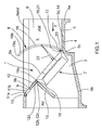
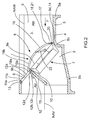
- the paddle wheel and the housing 10 are arranged so as to be suitable and intended to be arranged in one or the other of two positions, a downward position immersed in the channel 3, for an electrical production function ( figures 1 and 2 ), and a raised raised position (not shown) for a function of access to the turbine assembly 7 and / or release of the passage channel 3 of the flow of water F.
- the lower transverse edge 14 of the main part 9a, and therefore of the turbine assembly 7, and thus of its supporting structure 9, is, in the immersed downward position, close to or adjacent to the floor 5.
- the lower transverse edge 14 comes to rest on a transverse seat 5d formed towards the recess 5c.
- the seat 5d and the axis 13 are arranged longitudinally offset, the first to the upstream side AM and the second to the downstream side AV, so that the main plane of the turbine assembly 7 in the immersed down position is inclined from upstream to downstream and from bottom to top with an angle of between 35 ° and 60 °.
- the turbine assembly 7 is equipped on the upstream side and facing the opening of the casing 10 of an intake grille of the water flow F (not shown) adapted and intended to stop by its upstream side of the debris conveyed by the water flow F of a larger size than the passages it contains.
- the grid assembly 8 can be described as a pre-grid assembly 8.
- the turbine assembly 7 is equipped with the upstream side of a screen (not shown), in particular a rotary screen, associated with the inlet grille of the turbine assembly 7. .
- valve 12 which is part of a valve assembly also having a valve opening 12a extending downwardly of the opening 11b.
- the valve 12 is located so as to be adjacent to and above the upper portion 10a of the edge of the housing 10.
- the valve 12 is adapted and intended to be arranged in and through the channel 3.
- the valve 12 is adapted and intended to be disposed in one or the other of two positions. In an erect closing position ( figure 1 ), the plane of the valve 12 is in the main plane of the turbine assembly 7 or in a neighboring plane. The valve 12 then closes the valve opening 12a. Thus, the valve 12 provides a function of stopping the blade of the water flow F facing the upstream side AM and it defines the nominal level upstream side NAM.
- valve 12 In a folded opening position ( figure 2 ), the valve 12 is disposed horizontally or substantially horizontally and being directed towards the downstream side AV. It then leaves open the valve opening 12a. It then provides a function of passage of the flow of water from upstream to downstream through the valve opening 12a.
- valve 12 It is also provided means for associating the valve 12 with a structure, such that, in the embodiment shown, the supporting structure 9 of the turbine assembly 7, the valve assembly 12, 12a and the turbine assembly 7 being then structurally associated with each other.
- the association means of the valve 12 have a structure adapted to allow the displacement of the valve 12a so that it is fit and intended to be disposed in one or the other of its two erected positions of closure and folded of opening.
- the association means of the valve 12 have a structure, in particular of the type comprising a shaft mounted in a bearing, suitable for allowing the valve 12 to pivot about a transversely disposed axis 12b, in particular towards the lower transverse edge 12c of the valve, towards the edge of the upper portion 10a of the housing 10, in particular on an angular stroke between the erected closed position and the folded open position, between the order of 50 ° to 90 °.
- valve 12 which, responsive to a control or to control means, are adapted and intended to move the valve 12 between one and the other of its two positions and to keep him in one of his two positions.
- means for moving and maintaining the valve 12 are chosen for example from the range comprising linear displacement means such as a cylinder, or rotary displacement means such as a rotary motor, or manual means.
- partition wall and deflection 15 which extends downstream of the turbine assembly 7 and the valve assembly 12, 12a.
- This partition and deflection wall 15 is disposed between the edge of the upper portion 10a of the housing 10 and the lower transverse edge 12d of the valve opening 12a. Thus, one can separate the respective water flows through the housing 10 and the valve opening 12a.
- This partition wall and detection 15 is here inclined upstream downstream and from top to bottom.
- the grid (or pre-grid, as previously indicated) assembly 8 firstly includes a grid 16, which can be arranged in and through the channel 3. It includes, secondly, a supporting structure 17 of the grid 15.
- the grid 16 has solid portions which may be typically bars, in particular regularly spaced, extending generally parallel to each other in a direction capable of being erected. It also includes free passages. In the case where the turbine assembly 7 is equipped with an intake grid of the water flow as previously indicated, its passages are of a size smaller than the size of the passages of the grid 16 of the assembly to grid 8.
- association means 18 of the grid 16 to the supporting structure 9 of the turbine assembly 7, in the embodiment shown in the figures. But in others conceivable embodiments, the association means 18 of the grid 16 are associated alternately or cumulatively with the structure 4 of the water supply structure 2.
- the association means 18 of the grid 15 have a structure adapted to allow the displacement of at least the upper portion of the gate 16 opposite to the base 5 so that it is suitable and intended to be arranged in one or the other of two possible positions: an erected position ( figure 1 ) and a folded position ( figure 2 ).
- the grid 16 In its erected position, the grid 16 is erected so that it intersects the channel 3 so that the entire flow of water flowing therethrough, from the upstream side AM to the downstream side AV.
- the gate 16 provides a debris stop function, stopping by its upstream side the debris conveyed by the water flow of a size greater than that of the passages it comprises.
- the valve 12 in the erected closing position, performs its closing function.
- the grid 16 In its folded position, the grid 16 is less inclined on the horizontal and provides a function of evacuation of floating debris that have been stopped by the grid 16. These debris are discharged downstream of the grid16 by passing over its upper transverse edge 19a, which upper transverse edge 19a is located at the valve opening 12a, then open since the valve 12 is in its folded opening position, while the upper part 19b of the gate 16 , adjacent to the edge 19a is located above, and in particular at least slightly downstream, the edge of the upper portion 10a of the housing 10.
- the valve opening 12a provides a floating debris flushing function stopped by the gate 16, downstream of the valve 12 and via the valve opening 12a, without the debris discharged through the blade wheel, given the presence and disposition of the partition wall and deflection 15.
- the grid assembly 8 and the turbine assembly 7 are arranged in the vicinity of each other, in particular in an adjacent manner, and structurally associated with one another to form a whole, means of association 18 of the grid 16 being then associated with the supporting structure 9 of the turbine assembly 7, as previously indicated.
- the grid assembly and the turbine assembly are structurally dissociated from each other.
- the association means of the grid are then associated with the structure of the water supply structure or the supporting structure of the turbine assembly.
- the object of the invention is also the hydraulic unit 1 comprising the grid assembly 8 and the turbine assembly 7 structurally associated with each other to form a whole, and only the grid assembly 8 as far as it is suitable. and intended to be structurally associated with the turbine assembly 7 or that it is intended to be structurally dissociated from the turbine assembly 7, but functionally associated with it in the hydraulic power station in situation.
- the following description relates more particularly to the embodiment in which the grid assembly 8 and the turbine assembly 7 are structurally associated with each other to form a whole.
- the embodiment in which the two sets 7 and 8 are dissociated is within the reach of the skilled person.
- the erected and folded positions concern at least the upper portion of the grid 16.
- these positions relate to the grid 16 itself which forms a solid whole, displaced as a whole and disposed in its together in one or other of the two positions erected and folded.
- the following description focuses more specifically on this achievement.
- the embodiment in which only the upper portion of the grid 16 is disposed in one or the other of the two positions emerged and folded is within the reach of the skilled person.
- the association means 18 of the grid 16 have a structure adapted to allow the pivoting of the grid 16 as a whole, around an axis 20 disposed transversely, close to or adjacent to the floor 5.
- the angular travel between the erected position and the folded position of the grid 16 is between the order of 35 ° to 55 °.
- the grid 16 is pivotally associated with the turbine assembly 7, and more particularly with its supporting structure 9, around the axis 20 close to or adjacent to the lower transverse edge 21 of the grid assembly 8, therefore of the grid 16, and lower transverse edge 14 of the turbine assembly 7, therefore of the structure 9.
- the association means 18 of the grid 16 are associated with the supporting structure 9 of the turbine assembly 7.
- the lower transverse edge 21 of the grid assembly 8 and the edge transverse lower 14 of the turbine assembly 7 are close to each other, in particular are adjacent.
- the grid 16 is also moved with the casing 10 of the turbine assembly 7, when the latter is arranged movably between the immersed downward position and the raised raised position.
- the association means 18 of the grid 17, which allow its pivoting between the erected and folded positions have for example a structure of the type comprising a shaft mounted in a bearing.
- the main plane of the turbine assembly 7 and the plane defined by the upper and lower transverse edges 19a and 21 of the grid assembly 8 extend in one or more adjacent planes inclined from upstream to downstream. and from bottom to top at an angle between 35 ° and 60 °.
- the grid assembly comprises means for moving and holding 22 of the grid 16 which, responsive to a control or to control means, are adapted and intended to move the grid 16 between one and the other of its two positions erected and folded and maintain it in one or the other of its two positions.
- Such displacement and holding means 22 of the gate 16 are, for example, chosen from the range comprising linear displacement means such as a jack, or rotary displacement means, such as a rotary motor, or manual means.
- the displacement and holding means 22 are interposed between the supporting structure 9 of the turbine assembly 7 and the grid 16.
- the grid 16 is curved in a constant or more or less constant manner, so that its convexity faces upstream and away from the turbine assembly 7 and that its concavity is downstream and towards the turbine assembly 7.
- the mean plane of the grid 16 is arranged so as to be vertical or close to the vertical.
- gate 16 protrudes above the upstream nominal level NAM, and even for example above channel 3, as can be seen on FIG. figure 1 .
- the radius of curvature and the center of curvature of the grid 16 are such that, in the folded position of the grid 16, the upper part 19b of the grid 16 is horizontal or slightly inclined to the horizontal, coming just above the edge of the upper portion 10a of the housing 10, the lower transverse edge 12d of the valve opening 12a, and the valve 12 then in the folded opening position.
- the upper transverse edge 19a of the grid 16 is placed in the lower part of the valve opening 12a.
- servo means for moving and holding means 22 of the gate 16 and means for moving and maintaining the valve 12 or their controls or control means.
- the control means of the screen moving means when such a screen is provided are associated with the servo means of the displacement and holding means 22 of the gate 16, or the means for moving and maintaining the valve 12, or their control means.
- the turbine assembly 7 is operated, a flow of water passing through it. We can thus produce electricity.
- the movement of the gate 16 is controlled and thus the gate 16 is moved from its position erected ( figure 1 ) to bring it to its folded position ( figure 2 ).
- valve 12 controls the movement of the valve 12 and thus moves the valve 12 from its erected closing position to bring it into its folded opening position.
- the upper transverse edge 19a of the gate 16 is located at the valve opening 12a and the floating debris previously stopped by the gate 16 are thus driven downstream of the valve 12 and via the valve opening 12a , without they pass through the impeller, which is not damaged, the operation of the turbine is not disturbed.
- the gate 16 in the folded position and the supply of the valve 12 in the folded position it brings the blades of the impeller in a position where they tend to close the passage of the water flow , which is made possible by the choice of a paddle wheel whose blades may be more or less inclined and thus close or open more or less the opening of the turbine.
Applications Claiming Priority (2)
| Application Number | Priority Date | Filing Date | Title |
|---|---|---|---|
| FR1154257A FR2975444B1 (fr) | 2011-05-17 | 2011-05-17 | Centrale hydraulique comportant un ensemble a grille d'admission d'eau dans la turbine agence pour evacuer des debris flottants arretes par la grille. |
| PCT/FR2012/050788 WO2012156604A1 (fr) | 2011-05-17 | 2012-04-11 | Centrale hydraulique comportant un ensemble a grille d'admission d'eau dans la turbine agence pour evacuer des debris flottants arretes par la grille. |
Publications (2)
| Publication Number | Publication Date |
|---|---|
| EP2710255A1 EP2710255A1 (fr) | 2014-03-26 |
| EP2710255B1 true EP2710255B1 (fr) | 2016-10-26 |
Family
ID=46147494
Family Applications (1)
| Application Number | Title | Priority Date | Filing Date |
|---|---|---|---|
| EP12722775.9A Not-in-force EP2710255B1 (fr) | 2011-05-17 | 2012-04-11 | Centrale hydraulique comportant un ensemble à grille d'admission d'eau dans la turbine agence pour evacuer des débris flottants arrétés par la grille. |
Country Status (8)
| Country | Link |
|---|---|
| US (1) | US9611607B2 (zh) |
| EP (1) | EP2710255B1 (zh) |
| JP (1) | JP5952389B2 (zh) |
| CN (1) | CN103688048B (zh) |
| BR (1) | BR112013029594A2 (zh) |
| CA (1) | CA2836350C (zh) |
| FR (1) | FR2975444B1 (zh) |
| WO (1) | WO2012156604A1 (zh) |
Families Citing this family (6)
| Publication number | Priority date | Publication date | Assignee | Title |
|---|---|---|---|---|
| DE102014226682B3 (de) * | 2014-12-19 | 2016-06-23 | Siemens Aktiengesellschaft | Unterwasserturbine zum Umwandeln von hydrodynamischer Energie in elektrische Energie und Verfahren zum Reinigen einer Unterwasserturbine |
| US10997258B2 (en) * | 2018-02-28 | 2021-05-04 | Fujitsu Limited | Bot networks |
| US10876265B2 (en) * | 2018-04-11 | 2020-12-29 | BVH, Inc. | Modular hydropower unit |
| CN109032098B (zh) * | 2018-08-28 | 2021-04-09 | 云南电网有限责任公司电力科学研究院 | 一种水电机组全工况单参数退化趋势分析方法 |
| CA3077753A1 (en) * | 2019-04-12 | 2020-10-12 | Cameron Farms Hutterite Colony | Fluid pumping apparatus and methods of use |
| US11066798B2 (en) * | 2019-06-13 | 2021-07-20 | Sea To Sky Energy Solutions Corp. | Water intake structure |
Family Cites Families (27)
| Publication number | Priority date | Publication date | Assignee | Title |
|---|---|---|---|---|
| US1606546A (en) * | 1926-11-09 | Hydraulic plant and screen thbrefqe | ||
| US1411945A (en) * | 1920-09-11 | 1922-04-04 | Frank O Wallene | Hydraulic apparatus |
| US1586754A (en) * | 1925-03-23 | 1926-06-01 | Morgan Smith S Co | Double rack for water supply |
| DE759178C (de) * | 1939-12-17 | 1953-08-17 | Arno Fischer | UEberflutbares Unterwasserkraftwerk fuer Flusslaeufe |
| US4319142A (en) * | 1980-09-25 | 1982-03-09 | Allis-Chalmers Corporation | Power generation unit for spillway gate structures |
| FR2531118A1 (fr) * | 1982-07-30 | 1984-02-03 | Durafour Construction | Element de barrage hydraulique et procedes pour son installation |
| US4415462A (en) * | 1982-08-12 | 1983-11-15 | Finch Harvey E | Self-cleaning screen |
| US4804855A (en) * | 1987-02-13 | 1989-02-14 | Obermeyer Henry K | Hydromotive machine apparatus and method of constructing the same |
| JPH09112495A (ja) * | 1995-10-13 | 1997-05-02 | Mitsubishi Heavy Ind Ltd | スクリーン装置 |
| US5954474A (en) * | 1996-03-28 | 1999-09-21 | Voith Hydro, Inc. | Hydro-turbine runner |
| US5754446A (en) * | 1996-08-19 | 1998-05-19 | Voith Hydro, Inc. | Method and apparatus for optimizing performance of a kaplan turbine |
| US6281597B1 (en) * | 1999-08-13 | 2001-08-28 | Syndicated Technologies, Llc. | Hydroelectric installation and method of constructing same |
| AT4390U1 (de) * | 2000-03-31 | 2001-06-25 | Steiner Reinhard Dipl Ing | Verfahren zur ermittlung der nettofallhöhe von turbinen |
| AT409505B (de) * | 2000-04-28 | 2002-09-25 | Hans Kuenz Ges M B H | Rechenreinigungseinrichtung |
| AT411369B (de) * | 2001-12-20 | 2003-12-29 | Va Tech Hydro Gmbh & Co | Verfahren zur herstellung einer wasserkraftanlage |
| FR2835548B1 (fr) | 2002-02-06 | 2004-04-30 | Cocguen Marie Louise Le | Module lineaire articule de desobstruction de grille d'admission de liquide contenant des dechets |
| DE10231744A1 (de) * | 2002-07-13 | 2004-01-22 | Hermann Henkel | Klappwehr |
| US6864596B2 (en) * | 2002-10-07 | 2005-03-08 | Voith Siemens Hydro Power Generation, Gmbh & Co. Kg | Hydrogen production from hydro power |
| AT413425B (de) * | 2003-03-06 | 2006-02-15 | Va Tech Hydro Gmbh & Co | Einrichtung zur erzeugung elektrischer energie |
| FR2862723B1 (fr) * | 2003-11-20 | 2006-04-28 | Jacques Fonkenell | Turbine et centrale hydraulique pour tres basse chute |
| FR2865226B1 (fr) * | 2004-01-19 | 2007-04-13 | Cismac Electronique | Barrage hydroelectrique modulaire prefabrique incorporant tout ou partie des equipements hydrauliques et electriques necessaires a son fonctionnement. |
| FR2874334B1 (fr) * | 2004-08-20 | 2006-11-24 | Beaudrey Et Cie Sa E | Tamis rotatif pour prise d'eau |
| CA2531708A1 (en) * | 2005-04-15 | 2006-10-15 | Edouard Petrounevitch | Modular system for generating electricity from moving fluid |
| JP2007187083A (ja) * | 2006-01-13 | 2007-07-26 | Shinko Electric Co Ltd | 小規模水力発電装置 |
| DE102010018806A1 (de) | 2010-04-29 | 2011-11-03 | Voith Patent Gmbh | Flusskraftwerk |
| US20100327586A1 (en) * | 2010-05-28 | 2010-12-30 | Technology Patents, Llc | Drainage, filtration, and electricity generating systems and methods |
| US20120187692A1 (en) * | 2011-01-21 | 2012-07-26 | Walton Randal D | Hydroelectric generators |
-
2011
- 2011-05-17 FR FR1154257A patent/FR2975444B1/fr not_active Expired - Fee Related
-
2012
- 2012-04-11 JP JP2014510853A patent/JP5952389B2/ja not_active Expired - Fee Related
- 2012-04-11 BR BR112013029594A patent/BR112013029594A2/pt active Search and Examination
- 2012-04-11 CA CA2836350A patent/CA2836350C/fr not_active Expired - Fee Related
- 2012-04-11 US US14/117,971 patent/US9611607B2/en active Active
- 2012-04-11 CN CN201280035073.3A patent/CN103688048B/zh not_active Expired - Fee Related
- 2012-04-11 EP EP12722775.9A patent/EP2710255B1/fr not_active Not-in-force
- 2012-04-11 WO PCT/FR2012/050788 patent/WO2012156604A1/fr active Application Filing
Non-Patent Citations (1)
| Title |
|---|
| None * |
Also Published As
| Publication number | Publication date |
|---|---|
| FR2975444A1 (fr) | 2012-11-23 |
| CA2836350C (fr) | 2018-08-28 |
| US20140102989A1 (en) | 2014-04-17 |
| CN103688048A (zh) | 2014-03-26 |
| EP2710255A1 (fr) | 2014-03-26 |
| WO2012156604A1 (fr) | 2012-11-22 |
| BR112013029594A2 (pt) | 2017-03-21 |
| FR2975444B1 (fr) | 2016-12-23 |
| JP5952389B2 (ja) | 2016-07-13 |
| CN103688048B (zh) | 2017-03-15 |
| CA2836350A1 (fr) | 2012-11-22 |
| US9611607B2 (en) | 2017-04-04 |
| JP2014513777A (ja) | 2014-06-05 |
Similar Documents
| Publication | Publication Date | Title |
|---|---|---|
| EP2710255B1 (fr) | Centrale hydraulique comportant un ensemble à grille d'admission d'eau dans la turbine agence pour evacuer des débris flottants arrétés par la grille. | |
| EP2307711B1 (fr) | Dispositif d'admission pour machine à turbine hydraulique respectueuse de l'environnement | |
| WO2005054667A2 (fr) | Turbine et centrale hydraulique pour tres basse chute | |
| EP3173529B1 (fr) | Dispositif de brassage de neige | |
| EP3061891A1 (fr) | Mécanisme de vidage pour une benne à béton comportant un réceptacle pour les fuites de laitance | |
| FR3132723A1 (fr) | Tête de dragage de sédiments pour robot subaquatique | |
| FR2946063A1 (fr) | Separateur de matieres, notamment pour poste de relevage d'eaux usees, et poste de relevage en comportant application. | |
| EP1441125A1 (fr) | Turbine hydraulique siphonée | |
| FR2531118A1 (fr) | Element de barrage hydraulique et procedes pour son installation | |
| CA3056705A1 (fr) | Dispositif pour la production d'energie hydro-electrique | |
| EP3633185B1 (fr) | Auget destiné à équiper la roue a augets d'une machine hydrolienne | |
| FR3138672A1 (fr) | Centrale hydroélectrique | |
| FR2730509A1 (fr) | Barrage flottant | |
| FR2843312A1 (fr) | Installation de decantage des eaux de ruissellement avec un repartiteur hydraulique | |
| WO2007093416A1 (fr) | Centrale hydroelectrique de tres basse chute | |
| EP3012374B1 (fr) | Dégrilleur à poutre flottante | |
| FR2891286A1 (fr) | Vanne de barrage integrant une turbine | |
| FR2982347A1 (fr) | Appareil de collecte et d'evacuation de poussieres | |
| FR3107637A1 (fr) | Dispositif pour la méthanisation de matière organique | |
| FR3010151A1 (fr) | Dispositif de production d'electricite a l'aide du courant d'un cours d'eau. | |
| WO2013098494A1 (fr) | Turbine hydraulique destinee notamment a une installation maremotrice | |
| FR2553803A1 (fr) | Degrilleur automatique | |
| FR2998311A1 (fr) | Amenagement du reseau d'alimentation en eau d'un generateur hydraulique | |
| FR2940334A1 (fr) | Deversoir installe en bordure d'un plan de liquide, notamment un plan d'eau | |
| FR2995032A1 (fr) | Barrage hydroelectrique gestionnaire des ecosystemes d'un bassin hydraugraphique |
Legal Events
| Date | Code | Title | Description |
|---|---|---|---|
| PUAI | Public reference made under article 153(3) epc to a published international application that has entered the european phase |
Free format text: ORIGINAL CODE: 0009012 |
|
| 17P | Request for examination filed |
Effective date: 20131206 |
|
| AK | Designated contracting states |
Kind code of ref document: A1 Designated state(s): AL AT BE BG CH CY CZ DE DK EE ES FI FR GB GR HR HU IE IS IT LI LT LU LV MC MK MT NL NO PL PT RO RS SE SI SK SM TR |
|
| DAX | Request for extension of the european patent (deleted) | ||
| REG | Reference to a national code |
Ref country code: DE Ref legal event code: R079 Ref document number: 602012024572 Country of ref document: DE Free format text: PREVIOUS MAIN CLASS: F03B0011080000 Ipc: E02B0009040000 |
|
| RIC1 | Information provided on ipc code assigned before grant |
Ipc: E02B 5/08 20060101ALI20160310BHEP Ipc: E02B 9/04 20060101AFI20160310BHEP Ipc: F03B 11/08 20060101ALI20160310BHEP Ipc: F03B 3/04 20060101ALI20160310BHEP Ipc: F03B 13/08 20060101ALI20160310BHEP Ipc: F03B 3/14 20060101ALI20160310BHEP Ipc: E02B 8/02 20060101ALI20160310BHEP |
|
| GRAP | Despatch of communication of intention to grant a patent |
Free format text: ORIGINAL CODE: EPIDOSNIGR1 |
|
| INTG | Intention to grant announced |
Effective date: 20160510 |
|
| GRAJ | Information related to disapproval of communication of intention to grant by the applicant or resumption of examination proceedings by the epo deleted |
Free format text: ORIGINAL CODE: EPIDOSDIGR1 |
|
| GRAR | Information related to intention to grant a patent recorded |
Free format text: ORIGINAL CODE: EPIDOSNIGR71 |
|
| GRAS | Grant fee paid |
Free format text: ORIGINAL CODE: EPIDOSNIGR3 |
|
| GRAA | (expected) grant |
Free format text: ORIGINAL CODE: 0009210 |
|
| INTC | Intention to grant announced (deleted) | ||
| AK | Designated contracting states |
Kind code of ref document: B1 Designated state(s): AL AT BE BG CH CY CZ DE DK EE ES FI FR GB GR HR HU IE IS IT LI LT LU LV MC MK MT NL NO PL PT RO RS SE SI SK SM TR |
|
| INTG | Intention to grant announced |
Effective date: 20160921 |
|
| REG | Reference to a national code |
Ref country code: GB Ref legal event code: FG4D Free format text: NOT ENGLISH |
|
| REG | Reference to a national code |
Ref country code: CH Ref legal event code: EP |
|
| REG | Reference to a national code |
Ref country code: AT Ref legal event code: REF Ref document number: 840140 Country of ref document: AT Kind code of ref document: T Effective date: 20161115 |
|
| REG | Reference to a national code |
Ref country code: IE Ref legal event code: FG4D Free format text: LANGUAGE OF EP DOCUMENT: FRENCH |
|
| REG | Reference to a national code |
Ref country code: DE Ref legal event code: R096 Ref document number: 602012024572 Country of ref document: DE |
|
| REG | Reference to a national code |
Ref country code: LT Ref legal event code: MG4D |
|
| PG25 | Lapsed in a contracting state [announced via postgrant information from national office to epo] |
Ref country code: LV Free format text: LAPSE BECAUSE OF FAILURE TO SUBMIT A TRANSLATION OF THE DESCRIPTION OR TO PAY THE FEE WITHIN THE PRESCRIBED TIME-LIMIT Effective date: 20161026 |
|
| REG | Reference to a national code |
Ref country code: NL Ref legal event code: MP Effective date: 20161026 |
|
| REG | Reference to a national code |
Ref country code: AT Ref legal event code: MK05 Ref document number: 840140 Country of ref document: AT Kind code of ref document: T Effective date: 20161026 |
|
| REG | Reference to a national code |
Ref country code: FR Ref legal event code: PLFP Year of fee payment: 6 |
|
| PG25 | Lapsed in a contracting state [announced via postgrant information from national office to epo] |
Ref country code: SE Free format text: LAPSE BECAUSE OF FAILURE TO SUBMIT A TRANSLATION OF THE DESCRIPTION OR TO PAY THE FEE WITHIN THE PRESCRIBED TIME-LIMIT Effective date: 20161026 Ref country code: NO Free format text: LAPSE BECAUSE OF FAILURE TO SUBMIT A TRANSLATION OF THE DESCRIPTION OR TO PAY THE FEE WITHIN THE PRESCRIBED TIME-LIMIT Effective date: 20170126 Ref country code: LT Free format text: LAPSE BECAUSE OF FAILURE TO SUBMIT A TRANSLATION OF THE DESCRIPTION OR TO PAY THE FEE WITHIN THE PRESCRIBED TIME-LIMIT Effective date: 20161026 Ref country code: GR Free format text: LAPSE BECAUSE OF FAILURE TO SUBMIT A TRANSLATION OF THE DESCRIPTION OR TO PAY THE FEE WITHIN THE PRESCRIBED TIME-LIMIT Effective date: 20170127 |
|
| PG25 | Lapsed in a contracting state [announced via postgrant information from national office to epo] |
Ref country code: RS Free format text: LAPSE BECAUSE OF FAILURE TO SUBMIT A TRANSLATION OF THE DESCRIPTION OR TO PAY THE FEE WITHIN THE PRESCRIBED TIME-LIMIT Effective date: 20161026 Ref country code: PT Free format text: LAPSE BECAUSE OF FAILURE TO SUBMIT A TRANSLATION OF THE DESCRIPTION OR TO PAY THE FEE WITHIN THE PRESCRIBED TIME-LIMIT Effective date: 20170227 Ref country code: ES Free format text: LAPSE BECAUSE OF FAILURE TO SUBMIT A TRANSLATION OF THE DESCRIPTION OR TO PAY THE FEE WITHIN THE PRESCRIBED TIME-LIMIT Effective date: 20161026 Ref country code: IS Free format text: LAPSE BECAUSE OF FAILURE TO SUBMIT A TRANSLATION OF THE DESCRIPTION OR TO PAY THE FEE WITHIN THE PRESCRIBED TIME-LIMIT Effective date: 20170226 Ref country code: FI Free format text: LAPSE BECAUSE OF FAILURE TO SUBMIT A TRANSLATION OF THE DESCRIPTION OR TO PAY THE FEE WITHIN THE PRESCRIBED TIME-LIMIT Effective date: 20161026 Ref country code: PL Free format text: LAPSE BECAUSE OF FAILURE TO SUBMIT A TRANSLATION OF THE DESCRIPTION OR TO PAY THE FEE WITHIN THE PRESCRIBED TIME-LIMIT Effective date: 20161026 Ref country code: AT Free format text: LAPSE BECAUSE OF FAILURE TO SUBMIT A TRANSLATION OF THE DESCRIPTION OR TO PAY THE FEE WITHIN THE PRESCRIBED TIME-LIMIT Effective date: 20161026 Ref country code: HR Free format text: LAPSE BECAUSE OF FAILURE TO SUBMIT A TRANSLATION OF THE DESCRIPTION OR TO PAY THE FEE WITHIN THE PRESCRIBED TIME-LIMIT Effective date: 20161026 Ref country code: NL Free format text: LAPSE BECAUSE OF FAILURE TO SUBMIT A TRANSLATION OF THE DESCRIPTION OR TO PAY THE FEE WITHIN THE PRESCRIBED TIME-LIMIT Effective date: 20161026 |
|
| REG | Reference to a national code |
Ref country code: DE Ref legal event code: R097 Ref document number: 602012024572 Country of ref document: DE |
|
| PG25 | Lapsed in a contracting state [announced via postgrant information from national office to epo] |
Ref country code: DK Free format text: LAPSE BECAUSE OF FAILURE TO SUBMIT A TRANSLATION OF THE DESCRIPTION OR TO PAY THE FEE WITHIN THE PRESCRIBED TIME-LIMIT Effective date: 20161026 Ref country code: EE Free format text: LAPSE BECAUSE OF FAILURE TO SUBMIT A TRANSLATION OF THE DESCRIPTION OR TO PAY THE FEE WITHIN THE PRESCRIBED TIME-LIMIT Effective date: 20161026 Ref country code: CZ Free format text: LAPSE BECAUSE OF FAILURE TO SUBMIT A TRANSLATION OF THE DESCRIPTION OR TO PAY THE FEE WITHIN THE PRESCRIBED TIME-LIMIT Effective date: 20161026 Ref country code: SK Free format text: LAPSE BECAUSE OF FAILURE TO SUBMIT A TRANSLATION OF THE DESCRIPTION OR TO PAY THE FEE WITHIN THE PRESCRIBED TIME-LIMIT Effective date: 20161026 Ref country code: RO Free format text: LAPSE BECAUSE OF FAILURE TO SUBMIT A TRANSLATION OF THE DESCRIPTION OR TO PAY THE FEE WITHIN THE PRESCRIBED TIME-LIMIT Effective date: 20161026 |
|
| PG25 | Lapsed in a contracting state [announced via postgrant information from national office to epo] |
Ref country code: IT Free format text: LAPSE BECAUSE OF FAILURE TO SUBMIT A TRANSLATION OF THE DESCRIPTION OR TO PAY THE FEE WITHIN THE PRESCRIBED TIME-LIMIT Effective date: 20161026 Ref country code: BG Free format text: LAPSE BECAUSE OF FAILURE TO SUBMIT A TRANSLATION OF THE DESCRIPTION OR TO PAY THE FEE WITHIN THE PRESCRIBED TIME-LIMIT Effective date: 20170126 Ref country code: SM Free format text: LAPSE BECAUSE OF FAILURE TO SUBMIT A TRANSLATION OF THE DESCRIPTION OR TO PAY THE FEE WITHIN THE PRESCRIBED TIME-LIMIT Effective date: 20161026 |
|
| PLBE | No opposition filed within time limit |
Free format text: ORIGINAL CODE: 0009261 |
|
| STAA | Information on the status of an ep patent application or granted ep patent |
Free format text: STATUS: NO OPPOSITION FILED WITHIN TIME LIMIT |
|
| 26N | No opposition filed |
Effective date: 20170727 |
|
| PG25 | Lapsed in a contracting state [announced via postgrant information from national office to epo] |
Ref country code: SI Free format text: LAPSE BECAUSE OF FAILURE TO SUBMIT A TRANSLATION OF THE DESCRIPTION OR TO PAY THE FEE WITHIN THE PRESCRIBED TIME-LIMIT Effective date: 20161026 |
|
| REG | Reference to a national code |
Ref country code: IE Ref legal event code: MM4A |
|
| PG25 | Lapsed in a contracting state [announced via postgrant information from national office to epo] |
Ref country code: MC Free format text: LAPSE BECAUSE OF FAILURE TO SUBMIT A TRANSLATION OF THE DESCRIPTION OR TO PAY THE FEE WITHIN THE PRESCRIBED TIME-LIMIT Effective date: 20161026 |
|
| PG25 | Lapsed in a contracting state [announced via postgrant information from national office to epo] |
Ref country code: LU Free format text: LAPSE BECAUSE OF NON-PAYMENT OF DUE FEES Effective date: 20170411 |
|
| REG | Reference to a national code |
Ref country code: FR Ref legal event code: PLFP Year of fee payment: 7 |
|
| PG25 | Lapsed in a contracting state [announced via postgrant information from national office to epo] |
Ref country code: IE Free format text: LAPSE BECAUSE OF NON-PAYMENT OF DUE FEES Effective date: 20170411 |
|
| PG25 | Lapsed in a contracting state [announced via postgrant information from national office to epo] |
Ref country code: MT Free format text: LAPSE BECAUSE OF FAILURE TO SUBMIT A TRANSLATION OF THE DESCRIPTION OR TO PAY THE FEE WITHIN THE PRESCRIBED TIME-LIMIT Effective date: 20161026 |
|
| PG25 | Lapsed in a contracting state [announced via postgrant information from national office to epo] |
Ref country code: HU Free format text: LAPSE BECAUSE OF FAILURE TO SUBMIT A TRANSLATION OF THE DESCRIPTION OR TO PAY THE FEE WITHIN THE PRESCRIBED TIME-LIMIT; INVALID AB INITIO Effective date: 20120411 |
|
| PG25 | Lapsed in a contracting state [announced via postgrant information from national office to epo] |
Ref country code: CY Free format text: LAPSE BECAUSE OF NON-PAYMENT OF DUE FEES Effective date: 20161026 |
|
| PG25 | Lapsed in a contracting state [announced via postgrant information from national office to epo] |
Ref country code: MK Free format text: LAPSE BECAUSE OF FAILURE TO SUBMIT A TRANSLATION OF THE DESCRIPTION OR TO PAY THE FEE WITHIN THE PRESCRIBED TIME-LIMIT Effective date: 20161026 |
|
| PG25 | Lapsed in a contracting state [announced via postgrant information from national office to epo] |
Ref country code: TR Free format text: LAPSE BECAUSE OF FAILURE TO SUBMIT A TRANSLATION OF THE DESCRIPTION OR TO PAY THE FEE WITHIN THE PRESCRIBED TIME-LIMIT Effective date: 20161026 |
|
| PG25 | Lapsed in a contracting state [announced via postgrant information from national office to epo] |
Ref country code: AL Free format text: LAPSE BECAUSE OF FAILURE TO SUBMIT A TRANSLATION OF THE DESCRIPTION OR TO PAY THE FEE WITHIN THE PRESCRIBED TIME-LIMIT Effective date: 20161026 |
|
| PGFP | Annual fee paid to national office [announced via postgrant information from national office to epo] |
Ref country code: DE Payment date: 20200513 Year of fee payment: 9 Ref country code: CH Payment date: 20200528 Year of fee payment: 9 Ref country code: FR Payment date: 20200429 Year of fee payment: 9 |
|
| PGFP | Annual fee paid to national office [announced via postgrant information from national office to epo] |
Ref country code: GB Payment date: 20200527 Year of fee payment: 9 Ref country code: BE Payment date: 20200429 Year of fee payment: 9 |
|
| REG | Reference to a national code |
Ref country code: DE Ref legal event code: R119 Ref document number: 602012024572 Country of ref document: DE |
|
| GBPC | Gb: european patent ceased through non-payment of renewal fee |
Effective date: 20210411 |
|
| REG | Reference to a national code |
Ref country code: BE Ref legal event code: MM Effective date: 20210430 |
|
| PG25 | Lapsed in a contracting state [announced via postgrant information from national office to epo] |
Ref country code: FR Free format text: LAPSE BECAUSE OF NON-PAYMENT OF DUE FEES Effective date: 20210430 Ref country code: GB Free format text: LAPSE BECAUSE OF NON-PAYMENT OF DUE FEES Effective date: 20210411 Ref country code: DE Free format text: LAPSE BECAUSE OF NON-PAYMENT OF DUE FEES Effective date: 20211103 Ref country code: LI Free format text: LAPSE BECAUSE OF NON-PAYMENT OF DUE FEES Effective date: 20210430 Ref country code: CH Free format text: LAPSE BECAUSE OF NON-PAYMENT OF DUE FEES Effective date: 20210430 |
|
| PG25 | Lapsed in a contracting state [announced via postgrant information from national office to epo] |
Ref country code: BE Free format text: LAPSE BECAUSE OF NON-PAYMENT OF DUE FEES Effective date: 20210430 |