EP2710255B1 - Hydro-electric power plant comprising a grating assembly for taking water into the turbine, which is designed to discharge floating debris stopped by the grating - Google Patents
Hydro-electric power plant comprising a grating assembly for taking water into the turbine, which is designed to discharge floating debris stopped by the grating Download PDFInfo
- Publication number
- EP2710255B1 EP2710255B1 EP12722775.9A EP12722775A EP2710255B1 EP 2710255 B1 EP2710255 B1 EP 2710255B1 EP 12722775 A EP12722775 A EP 12722775A EP 2710255 B1 EP2710255 B1 EP 2710255B1
- Authority
- EP
- European Patent Office
- Prior art keywords
- grating
- flap valve
- assembly
- turbine unit
- power plant
- Prior art date
- Legal status (The legal status is an assumption and is not a legal conclusion. Google has not performed a legal analysis and makes no representation as to the accuracy of the status listed.)
- Not-in-force
Links
- XLYOFNOQVPJJNP-UHFFFAOYSA-N water Substances O XLYOFNOQVPJJNP-UHFFFAOYSA-N 0.000 title claims description 76
- 238000011144 upstream manufacturing Methods 0.000 claims description 54
- 238000006073 displacement reaction Methods 0.000 claims description 20
- 239000007787 solid Substances 0.000 claims description 6
- 238000000034 method Methods 0.000 claims description 5
- 230000005611 electricity Effects 0.000 claims description 3
- 230000014759 maintenance of location Effects 0.000 claims 10
- 238000000638 solvent extraction Methods 0.000 claims 2
- 230000001419 dependent effect Effects 0.000 claims 1
- 238000007599 discharging Methods 0.000 claims 1
- 241000940835 Pales Species 0.000 description 13
- 206010033546 Pallor Diseases 0.000 description 13
- 230000004907 flux Effects 0.000 description 9
- 238000005192 partition Methods 0.000 description 6
- 230000000712 assembly Effects 0.000 description 4
- 238000000429 assembly Methods 0.000 description 4
- 241001465754 Metazoa Species 0.000 description 2
- 238000004140 cleaning Methods 0.000 description 2
- 230000009977 dual effect Effects 0.000 description 2
- 238000011010 flushing procedure Methods 0.000 description 2
- 239000010813 municipal solid waste Substances 0.000 description 2
- 241001080024 Telles Species 0.000 description 1
- 238000004891 communication Methods 0.000 description 1
- 238000001514 detection method Methods 0.000 description 1
- 230000009189 diving Effects 0.000 description 1
- 230000000694 effects Effects 0.000 description 1
- 230000001788 irregular Effects 0.000 description 1
- 238000004519 manufacturing process Methods 0.000 description 1
- 238000004806 packaging method and process Methods 0.000 description 1
- 238000005381 potential energy Methods 0.000 description 1
- ZJFJVRPLNAMIKH-UHFFFAOYSA-N pseudo-u Chemical compound O=C1NC(=O)C(C)=CN1C1OC(COP(O)(=S)OC2C(OC(C2)N2C(N=C(N)C=C2)=O)COP(O)(=S)OC2C(OC(C2)N2C(N=C(N)C=C2)=O)COP(O)(=S)OC2C(OC(C2)N2C(N=C(N)C=C2)=O)COP(O)(=S)OC2C(OC(C2)N2C(NC(=O)C(C)=C2)=O)COP(O)(=S)OC2C(OC(C2)N2C3=C(C(NC(N)=N3)=O)N=C2)COP(O)(=S)OC2C(OC(C2)N2C3=NC=NC(N)=C3N=C2)COP(O)(=S)OC2C(OC(C2)N2C3=NC=NC(N)=C3N=C2)COP(O)(=S)OC2C(OC(C2)N2C(N=C(N)C=C2)=O)COP(O)(=S)OC2C(OC(C2)N2C(NC(=O)C(C)=C2)=O)COP(O)(=S)OC2C(OC(C2)N2C(NC(=O)C(C)=C2)=O)COP(O)(=S)OC2C(OC(C2)N2C3=C(C(NC(N)=N3)=O)N=C2)COP(O)(=S)OC2C(OC(C2)N2C3=C(C(NC(N)=N3)=O)N=C2)COP(O)(=S)OC2C(OC(C2)N2C3=C(C(NC(N)=N3)=O)N=C2)COP(O)(=S)OC2C(OC(C2)N2C3=NC=NC(N)=C3N=C2)CO)C(O)C1 ZJFJVRPLNAMIKH-UHFFFAOYSA-N 0.000 description 1
Images
Classifications
-
- E—FIXED CONSTRUCTIONS
- E02—HYDRAULIC ENGINEERING; FOUNDATIONS; SOIL SHIFTING
- E02B—HYDRAULIC ENGINEERING
- E02B5/00—Artificial water canals, e.g. irrigation canals
- E02B5/08—Details, e.g. gates, screens
- E02B5/085—Arresting devices for waterborne materials, e.g. gratings
-
- B—PERFORMING OPERATIONS; TRANSPORTING
- B01—PHYSICAL OR CHEMICAL PROCESSES OR APPARATUS IN GENERAL
- B01D—SEPARATION
- B01D29/00—Filters with filtering elements stationary during filtration, e.g. pressure or suction filters, not covered by groups B01D24/00 - B01D27/00; Filtering elements therefor
- B01D29/96—Filters with filtering elements stationary during filtration, e.g. pressure or suction filters, not covered by groups B01D24/00 - B01D27/00; Filtering elements therefor in which the filtering elements are moved between filtering operations; Particular measures for removing or replacing the filtering elements; Transport systems for filters
- B01D29/965—Device for changing the inclination of the filtering element
-
- B—PERFORMING OPERATIONS; TRANSPORTING
- B01—PHYSICAL OR CHEMICAL PROCESSES OR APPARATUS IN GENERAL
- B01D—SEPARATION
- B01D35/00—Filtering devices having features not specifically covered by groups B01D24/00 - B01D33/00, or for applications not specifically covered by groups B01D24/00 - B01D33/00; Auxiliary devices for filtration; Filter housing constructions
- B01D35/02—Filters adapted for location in special places, e.g. pipe-lines, pumps, stop-cocks
-
- E—FIXED CONSTRUCTIONS
- E02—HYDRAULIC ENGINEERING; FOUNDATIONS; SOIL SHIFTING
- E02B—HYDRAULIC ENGINEERING
- E02B8/00—Details of barrages or weirs ; Energy dissipating devices carried by lock or dry-dock gates
- E02B8/02—Sediment base gates; Sand sluices; Structures for retaining arresting waterborne material
- E02B8/023—Arresting devices for waterborne materials
-
- F—MECHANICAL ENGINEERING; LIGHTING; HEATING; WEAPONS; BLASTING
- F03—MACHINES OR ENGINES FOR LIQUIDS; WIND, SPRING, OR WEIGHT MOTORS; PRODUCING MECHANICAL POWER OR A REACTIVE PROPULSIVE THRUST, NOT OTHERWISE PROVIDED FOR
- F03B—MACHINES OR ENGINES FOR LIQUIDS
- F03B11/00—Parts or details not provided for in, or of interest apart from, the preceding groups, e.g. wear-protection couplings, between turbine and generator
- F03B11/08—Parts or details not provided for in, or of interest apart from, the preceding groups, e.g. wear-protection couplings, between turbine and generator for removing foreign matter, e.g. mud
-
- F—MECHANICAL ENGINEERING; LIGHTING; HEATING; WEAPONS; BLASTING
- F03—MACHINES OR ENGINES FOR LIQUIDS; WIND, SPRING, OR WEIGHT MOTORS; PRODUCING MECHANICAL POWER OR A REACTIVE PROPULSIVE THRUST, NOT OTHERWISE PROVIDED FOR
- F03B—MACHINES OR ENGINES FOR LIQUIDS
- F03B13/00—Adaptations of machines or engines for special use; Combinations of machines or engines with driving or driven apparatus; Power stations or aggregates
- F03B13/08—Machine or engine aggregates in dams or the like; Conduits therefor, e.g. diffusors
-
- F—MECHANICAL ENGINEERING; LIGHTING; HEATING; WEAPONS; BLASTING
- F03—MACHINES OR ENGINES FOR LIQUIDS; WIND, SPRING, OR WEIGHT MOTORS; PRODUCING MECHANICAL POWER OR A REACTIVE PROPULSIVE THRUST, NOT OTHERWISE PROVIDED FOR
- F03B—MACHINES OR ENGINES FOR LIQUIDS
- F03B3/00—Machines or engines of reaction type; Parts or details peculiar thereto
- F03B3/04—Machines or engines of reaction type; Parts or details peculiar thereto with substantially axial flow throughout rotors, e.g. propeller turbines
-
- F—MECHANICAL ENGINEERING; LIGHTING; HEATING; WEAPONS; BLASTING
- F03—MACHINES OR ENGINES FOR LIQUIDS; WIND, SPRING, OR WEIGHT MOTORS; PRODUCING MECHANICAL POWER OR A REACTIVE PROPULSIVE THRUST, NOT OTHERWISE PROVIDED FOR
- F03B—MACHINES OR ENGINES FOR LIQUIDS
- F03B3/00—Machines or engines of reaction type; Parts or details peculiar thereto
- F03B3/12—Blades; Blade-carrying rotors
- F03B3/14—Rotors having adjustable blades
-
- E—FIXED CONSTRUCTIONS
- E02—HYDRAULIC ENGINEERING; FOUNDATIONS; SOIL SHIFTING
- E02B—HYDRAULIC ENGINEERING
- E02B9/00—Water-power plants; Layout, construction or equipment, methods of, or apparatus for, making same
- E02B9/02—Water-ways
- E02B9/04—Free-flow canals or flumes; Intakes
-
- Y—GENERAL TAGGING OF NEW TECHNOLOGICAL DEVELOPMENTS; GENERAL TAGGING OF CROSS-SECTIONAL TECHNOLOGIES SPANNING OVER SEVERAL SECTIONS OF THE IPC; TECHNICAL SUBJECTS COVERED BY FORMER USPC CROSS-REFERENCE ART COLLECTIONS [XRACs] AND DIGESTS
- Y02—TECHNOLOGIES OR APPLICATIONS FOR MITIGATION OR ADAPTATION AGAINST CLIMATE CHANGE
- Y02E—REDUCTION OF GREENHOUSE GAS [GHG] EMISSIONS, RELATED TO ENERGY GENERATION, TRANSMISSION OR DISTRIBUTION
- Y02E10/00—Energy generation through renewable energy sources
- Y02E10/20—Hydro energy
Definitions
- the invention relates to the protection of turbines of hydraulic power plants installed on water supply works, against the debris conveyed by the water which, if they crossed the impeller blades of the turbines, would be likely to deteriorate them or disrupt their operation.
- the invention relates more specifically to the evacuation of floating debris stopped by the grids of the grid assemblies which are provided with such hydraulic power plants without these debris passing through the impeller wheels of the turbine assemblies.
- the object of the invention is first and foremost a hydraulic power plant for a water supply structure such as including a flow channel of a flow of water limited by a structure having a base and two walls forming walls. comprising, functionally associated, downstream, a turbine assembly as just defined, and, upstream, an intake grid assembly of the water flow.
- the subject of the invention is, secondly, a grid assembly intended to be functionally associated with a turbine assembly, to form such a hydraulic power station.
- the subject of the invention is a method of implementing such a hydraulic unit in order to evacuate floating debris stopped by the grid.
- the document FR-A-2862723 describes a turbine assembly for a hydraulic power plant of the type which is the subject of the invention.
- a hydraulic power plant is intended to equip a stream at a very low drop of less than 10 meters, and preferably 1 to 5 meters. It comprises a paddle wheel, the ratio between the kinetic energy of the water flow at the outlet of the wheel and the potential energy of the fall being less than 20%.
- the turbine assembly is equipped with the upstream side and opposite the opening of the housing of the paddle wheel of a water flow intake grille suitable and intended to stop by its upstream side of the debris conveyed by the water flow of a size greater than that of the passages it comprises.
- the turbine assembly is equipped with the upstream side which is the grid in question, a screen with rotating arms associated with the gate having the function of unclog debris accumulating on it on the upstream side.
- an inlet pre-grid of suitable water flow and intended to be mounted with a position erected in and through the channel of the water supply structure. water, upstream of the turbine assembly.
- This pre-grid has passages of a size larger than the size of the passages of the grid equipping the turbine assembly.
- the pre-grid is adapted and intended to stop debris conveyed by the flow of large water, while the grid equipping the turbine assembly is adapted and intended to stop debris of smaller size.
- the pre-grid and the grid therefore combine their effects.
- Such an intake pre-grid is part of an intake grid assembly of the water flow which, in addition to the pre-grid, includes means for associating the pre-grid with the supporting structure of the assembly. turbine or, more frequently, to the structure of the water supply structure.
- the document FR-A-2835548 discloses an articulated linear grating unblocking module, comprising a scraper carried at the end of a movable arm, which makes this device unsuitable, as previously indicated.
- the document US 1,586,754 is a dual rack water supply device, with a pre-grid or front rack to stop debris.
- the retaining grid or bottom rack is then inactive.
- the dual rack device is in the up position, the pre-rack or front rack is disposed substantially horizontally and a valve is open, so that the debris that was on the pre-grid is sent into a tank and a passage who is in communication with a space.
- the water then passes through the retaining grid or bottom rack that holds the debris.
- the door is opened and the water is passed over the pre-grid, into the canal or passageway, and at the same time the debris from the pre-grid is washed out. -changing in the channel or passage around the turbine and downstream. So, the door is according to what you want, open or closed.
- the grid assembly and the turbine assembly are either arranged in the vicinity of each other, in particular adjacent, and structurally associated with each other to form a whole, the means of association the grid then being associated with the supporting structure of the turbine assembly, or structurally dissociated from one another, the means of association of the grid being then associated with the structure of the adduction structure d water or the supporting structure of the turbine assembly.
- the lower transverse edge of the grid assembly and the lower transverse edge of the turbine assembly are close to one another, in particular are adjacent, in particular are close to, or adjacent to, raft.
- the means for associating the gate have a structure, in particular of the type comprising a shaft mounted in a bearing, suitable for allowing the pivoting of at least the upper portion of the gate, around an axis arranged transversely.
- the grid forms a solid whole, moved as a whole and disposed as a whole in one or other of the two erected and folded positions.
- the association means of the grid have a structure adapted to allow the pivoting of the grid, about an axis arranged transversely, close to or adjacent to the raft, in particular on an angular stroke between the erected position and the folded position, between the order of 35 ° to 55 °.
- the grid is pivotally associated with the turbine assembly about an axis disposed transversely, close to or adjacent to the lower transverse edge of the grid assembly and lower transverse edge of the assembly. turbine. And the association means of the grid are associated with the supporting structure of the turbine assembly.
- the means for moving and maintaining the gate are chosen from the range comprising linear displacement means such as a jack, or rotary displacement means, such as a rotary motor, or manual means.
- the grid comprises bars, in particular regularly spaced, extending generally parallel to each other in a direction capable of being erected.
- the grid is curved convexly facing upstream and opposite the turbine assembly and concavity facing downstream and towards the turbine assembly, so that in the folded position, the upper part of the grid is apt and intended to be horizontal or slightly inclined to the horizontal.
- valve assembly and the turbine assembly are structurally associated with each other, the valve association means being associated with the supporting structure of the turbine assembly.
- the means for associating the valve have a structure, in particular of the type comprising a shaft mounted in a bearing, suitable for allowing the valve to pivot about an axis arranged transversely, in particular towards the lower transverse edge of the valve. valve, towards the upper edge of the caster of the paddle wheel and in the vicinity of the upper transverse edge of the gate in the folded position, in particular on an angular stroke between the erected closed position and the folded position of opening, included between the order of 50 ° to 90 °.
- the means for moving and maintaining the valve are selected from the range comprising linear displacement means such as a cylinder, or rotary displacement means such as a rotary motor, or manual means.
- the hydraulic unit further comprises means for detecting the degree of clogging of the gate associated with the servocontrol means of the means for moving and holding the gate, the means for moving and maintaining the valve, or for their control means.
- the main plane of the turbine assembly, the plane of the valve in its erect closure position, and the plane defined by the upper and lower transverse edges of the grid assembly extend in one or more planes. , in particular neighbors, inclined from upstream to downstream and from bottom to top with an angle of between 35 ° and 60 °.
- the hydraulic unit further comprises a partition wall and deflection which extends downstream of the turbine assembly and the valve assembly, is disposed between the upper portion of the edge of the housing of the paddle wheel and the lower transverse edge of the valve opening so as to separate the respective water flows therethrough, said partition wall and deflection being inclined from upstream to downstream and from top to bottom.
- the turbine assembly is equipped on the upstream side and opposite the opening of the caster of the impeller of a water intake intake grille adapted and intended to stop by its upstream side of debris conveyed by the water flow of a size greater than that of the passages it comprises, these passages being of a size smaller than the size of the passages of the grid of the grid assembly, which then constitutes a set to pre-grid.
- the turbine assembly is equipped with the upstream side of a screen, in particular with a rotary screen, associated with the inlet grille of the turbine assembly, and in which the control means of the turbine assembly means of movement of the screen are associated with the servo means of the means for moving and maintaining the gate, or the means for moving and maintaining the valve, or their control means.
- the paddle wheel and the casing of the turbine assembly are arranged so as to be suitable and intended to be arranged in one or the other of two positions, a submerged downward position for an electrical generating function, and a raised raised position for a function of access to the turbine assembly and / or release of the passage channel of the water flow.
- the gate of the grid assembly is also moved with the casing of the turbine assembly.
- the gate With the feed of the gate in the folded position and the bringing of the valve in the folded position, it brings the blades of the impeller in a position where they tend to close the passage of the flow of water.
- the water supply structure 2 includes a flow channel 3 of a water flow F and a structure 4 having a floor or bottom 5 and two walls forming walls 6.
- the channel 3 has for example in cross section a general shape of U or pseudo-U.
- the flow of the water flow F is in the direction from the upstream AM to the downstream AV.
- the raft 5 is typically plane and generally horizontal or slightly inclined to the horizontal. It comprises in the embodiment shown an upstream portion 5a and a downstream portion 5b located at a lower level than the upstream portion, a recess 5c downwardly connecting the upstream portion 5a to the downstream portion 5b.
- bajoyers 6 are typically vertical or substantially vertical and parallel to each other.
- NAM is still defined as the nominal water level upstream AM and NAV as the nominal water level downstream AV.
- the flow of water F is for example the flow of a watercourse or a diversion of a watercourse.
- the flow of water arriving from the upstream side can carry down solid debris such as plant debris (leaves, branches, plants ... for example), animal debris (dead animals for example), debris of any other kind (rubbish, garbage, packaging, etc.).
- solid debris such as plant debris (leaves, branches, plants ... for example), animal debris (dead animals for example), debris of any other kind (rubbish, garbage, packaging, etc.).
- debris should be considered in its most generic acceptance. These debris are of a more or less regular or irregular size and of a larger or smaller size.
- the hydraulic unit 1 comprises, functionally associated with each other, namely, downstream, a specific turbine assembly 7 and, upstream, an inlet grille assembly of the water flow 8.
- a specific turbine assembly 7 and, upstream, an inlet grille assembly of the water flow 8.
- One and the other are suitable and intended to be installed in and through the channel 3.
- the invention is also aimed at the case where the hydraulic unit 1 comprises several turbine assemblies 7 and / or a plurality of grid assemblies 8, arranged side by side in the channel 3.
- Such a turbine assembly 7 is of the general type described in the document FR-A-2862723 .
- Such a turbine assembly 7 includes a bearing structure 9 and a paddle wheel turbine mounted in a casing 10 having a flat cylinder shape with an opening on the upstream side and an opening on the downstream side.
- the supporting structure 9 extends in a plane which is the main plane of the turbine assembly 7, or which is parallel to the main plane of the turbine assembly 7.
- the turbine is for example KAPLAN type and, in any case, the blades are mounted so as to be inclined more or less around radial axes, the paddle wheel being more or less open or more or less closed.
- the supporting structure 9 has a main portion 9a where the housing 10 is located and an upper portion 9b extending the main portion 9a upwards.
- the main part 9a is closed except for the zone facing the openings of the housing 10.
- the upper part 9b comprises two lateral arms 11a on either side of an opening 11b, notwithstanding a valve 12.
- the lateral arms 11a are, at their upper end portions, mounted so as to be pivotable about an upper transverse axis 13.
- the paddle wheel and the housing 10 are arranged so as to be suitable and intended to be arranged in one or the other of two positions, a downward position immersed in the channel 3, for an electrical production function ( figures 1 and 2 ), and a raised raised position (not shown) for a function of access to the turbine assembly 7 and / or release of the passage channel 3 of the flow of water F.
- the lower transverse edge 14 of the main part 9a, and therefore of the turbine assembly 7, and thus of its supporting structure 9, is, in the immersed downward position, close to or adjacent to the floor 5.
- the lower transverse edge 14 comes to rest on a transverse seat 5d formed towards the recess 5c.
- the seat 5d and the axis 13 are arranged longitudinally offset, the first to the upstream side AM and the second to the downstream side AV, so that the main plane of the turbine assembly 7 in the immersed down position is inclined from upstream to downstream and from bottom to top with an angle of between 35 ° and 60 °.
- the turbine assembly 7 is equipped on the upstream side and facing the opening of the casing 10 of an intake grille of the water flow F (not shown) adapted and intended to stop by its upstream side of the debris conveyed by the water flow F of a larger size than the passages it contains.
- the grid assembly 8 can be described as a pre-grid assembly 8.
- the turbine assembly 7 is equipped with the upstream side of a screen (not shown), in particular a rotary screen, associated with the inlet grille of the turbine assembly 7. .
- valve 12 which is part of a valve assembly also having a valve opening 12a extending downwardly of the opening 11b.
- the valve 12 is located so as to be adjacent to and above the upper portion 10a of the edge of the housing 10.
- the valve 12 is adapted and intended to be arranged in and through the channel 3.
- the valve 12 is adapted and intended to be disposed in one or the other of two positions. In an erect closing position ( figure 1 ), the plane of the valve 12 is in the main plane of the turbine assembly 7 or in a neighboring plane. The valve 12 then closes the valve opening 12a. Thus, the valve 12 provides a function of stopping the blade of the water flow F facing the upstream side AM and it defines the nominal level upstream side NAM.
- valve 12 In a folded opening position ( figure 2 ), the valve 12 is disposed horizontally or substantially horizontally and being directed towards the downstream side AV. It then leaves open the valve opening 12a. It then provides a function of passage of the flow of water from upstream to downstream through the valve opening 12a.
- valve 12 It is also provided means for associating the valve 12 with a structure, such that, in the embodiment shown, the supporting structure 9 of the turbine assembly 7, the valve assembly 12, 12a and the turbine assembly 7 being then structurally associated with each other.
- the association means of the valve 12 have a structure adapted to allow the displacement of the valve 12a so that it is fit and intended to be disposed in one or the other of its two erected positions of closure and folded of opening.
- the association means of the valve 12 have a structure, in particular of the type comprising a shaft mounted in a bearing, suitable for allowing the valve 12 to pivot about a transversely disposed axis 12b, in particular towards the lower transverse edge 12c of the valve, towards the edge of the upper portion 10a of the housing 10, in particular on an angular stroke between the erected closed position and the folded open position, between the order of 50 ° to 90 °.
- valve 12 which, responsive to a control or to control means, are adapted and intended to move the valve 12 between one and the other of its two positions and to keep him in one of his two positions.
- means for moving and maintaining the valve 12 are chosen for example from the range comprising linear displacement means such as a cylinder, or rotary displacement means such as a rotary motor, or manual means.
- partition wall and deflection 15 which extends downstream of the turbine assembly 7 and the valve assembly 12, 12a.
- This partition and deflection wall 15 is disposed between the edge of the upper portion 10a of the housing 10 and the lower transverse edge 12d of the valve opening 12a. Thus, one can separate the respective water flows through the housing 10 and the valve opening 12a.
- This partition wall and detection 15 is here inclined upstream downstream and from top to bottom.
- the grid (or pre-grid, as previously indicated) assembly 8 firstly includes a grid 16, which can be arranged in and through the channel 3. It includes, secondly, a supporting structure 17 of the grid 15.
- the grid 16 has solid portions which may be typically bars, in particular regularly spaced, extending generally parallel to each other in a direction capable of being erected. It also includes free passages. In the case where the turbine assembly 7 is equipped with an intake grid of the water flow as previously indicated, its passages are of a size smaller than the size of the passages of the grid 16 of the assembly to grid 8.
- association means 18 of the grid 16 to the supporting structure 9 of the turbine assembly 7, in the embodiment shown in the figures. But in others conceivable embodiments, the association means 18 of the grid 16 are associated alternately or cumulatively with the structure 4 of the water supply structure 2.
- the association means 18 of the grid 15 have a structure adapted to allow the displacement of at least the upper portion of the gate 16 opposite to the base 5 so that it is suitable and intended to be arranged in one or the other of two possible positions: an erected position ( figure 1 ) and a folded position ( figure 2 ).
- the grid 16 In its erected position, the grid 16 is erected so that it intersects the channel 3 so that the entire flow of water flowing therethrough, from the upstream side AM to the downstream side AV.
- the gate 16 provides a debris stop function, stopping by its upstream side the debris conveyed by the water flow of a size greater than that of the passages it comprises.
- the valve 12 in the erected closing position, performs its closing function.
- the grid 16 In its folded position, the grid 16 is less inclined on the horizontal and provides a function of evacuation of floating debris that have been stopped by the grid 16. These debris are discharged downstream of the grid16 by passing over its upper transverse edge 19a, which upper transverse edge 19a is located at the valve opening 12a, then open since the valve 12 is in its folded opening position, while the upper part 19b of the gate 16 , adjacent to the edge 19a is located above, and in particular at least slightly downstream, the edge of the upper portion 10a of the housing 10.
- the valve opening 12a provides a floating debris flushing function stopped by the gate 16, downstream of the valve 12 and via the valve opening 12a, without the debris discharged through the blade wheel, given the presence and disposition of the partition wall and deflection 15.
- the grid assembly 8 and the turbine assembly 7 are arranged in the vicinity of each other, in particular in an adjacent manner, and structurally associated with one another to form a whole, means of association 18 of the grid 16 being then associated with the supporting structure 9 of the turbine assembly 7, as previously indicated.
- the grid assembly and the turbine assembly are structurally dissociated from each other.
- the association means of the grid are then associated with the structure of the water supply structure or the supporting structure of the turbine assembly.
- the object of the invention is also the hydraulic unit 1 comprising the grid assembly 8 and the turbine assembly 7 structurally associated with each other to form a whole, and only the grid assembly 8 as far as it is suitable. and intended to be structurally associated with the turbine assembly 7 or that it is intended to be structurally dissociated from the turbine assembly 7, but functionally associated with it in the hydraulic power station in situation.
- the following description relates more particularly to the embodiment in which the grid assembly 8 and the turbine assembly 7 are structurally associated with each other to form a whole.
- the embodiment in which the two sets 7 and 8 are dissociated is within the reach of the skilled person.
- the erected and folded positions concern at least the upper portion of the grid 16.
- these positions relate to the grid 16 itself which forms a solid whole, displaced as a whole and disposed in its together in one or other of the two positions erected and folded.
- the following description focuses more specifically on this achievement.
- the embodiment in which only the upper portion of the grid 16 is disposed in one or the other of the two positions emerged and folded is within the reach of the skilled person.
- the association means 18 of the grid 16 have a structure adapted to allow the pivoting of the grid 16 as a whole, around an axis 20 disposed transversely, close to or adjacent to the floor 5.
- the angular travel between the erected position and the folded position of the grid 16 is between the order of 35 ° to 55 °.
- the grid 16 is pivotally associated with the turbine assembly 7, and more particularly with its supporting structure 9, around the axis 20 close to or adjacent to the lower transverse edge 21 of the grid assembly 8, therefore of the grid 16, and lower transverse edge 14 of the turbine assembly 7, therefore of the structure 9.
- the association means 18 of the grid 16 are associated with the supporting structure 9 of the turbine assembly 7.
- the lower transverse edge 21 of the grid assembly 8 and the edge transverse lower 14 of the turbine assembly 7 are close to each other, in particular are adjacent.
- the grid 16 is also moved with the casing 10 of the turbine assembly 7, when the latter is arranged movably between the immersed downward position and the raised raised position.
- the association means 18 of the grid 17, which allow its pivoting between the erected and folded positions have for example a structure of the type comprising a shaft mounted in a bearing.
- the main plane of the turbine assembly 7 and the plane defined by the upper and lower transverse edges 19a and 21 of the grid assembly 8 extend in one or more adjacent planes inclined from upstream to downstream. and from bottom to top at an angle between 35 ° and 60 °.
- the grid assembly comprises means for moving and holding 22 of the grid 16 which, responsive to a control or to control means, are adapted and intended to move the grid 16 between one and the other of its two positions erected and folded and maintain it in one or the other of its two positions.
- Such displacement and holding means 22 of the gate 16 are, for example, chosen from the range comprising linear displacement means such as a jack, or rotary displacement means, such as a rotary motor, or manual means.
- the displacement and holding means 22 are interposed between the supporting structure 9 of the turbine assembly 7 and the grid 16.
- the grid 16 is curved in a constant or more or less constant manner, so that its convexity faces upstream and away from the turbine assembly 7 and that its concavity is downstream and towards the turbine assembly 7.
- the mean plane of the grid 16 is arranged so as to be vertical or close to the vertical.
- gate 16 protrudes above the upstream nominal level NAM, and even for example above channel 3, as can be seen on FIG. figure 1 .
- the radius of curvature and the center of curvature of the grid 16 are such that, in the folded position of the grid 16, the upper part 19b of the grid 16 is horizontal or slightly inclined to the horizontal, coming just above the edge of the upper portion 10a of the housing 10, the lower transverse edge 12d of the valve opening 12a, and the valve 12 then in the folded opening position.
- the upper transverse edge 19a of the grid 16 is placed in the lower part of the valve opening 12a.
- servo means for moving and holding means 22 of the gate 16 and means for moving and maintaining the valve 12 or their controls or control means.
- the control means of the screen moving means when such a screen is provided are associated with the servo means of the displacement and holding means 22 of the gate 16, or the means for moving and maintaining the valve 12, or their control means.
- the turbine assembly 7 is operated, a flow of water passing through it. We can thus produce electricity.
- the movement of the gate 16 is controlled and thus the gate 16 is moved from its position erected ( figure 1 ) to bring it to its folded position ( figure 2 ).
- valve 12 controls the movement of the valve 12 and thus moves the valve 12 from its erected closing position to bring it into its folded opening position.
- the upper transverse edge 19a of the gate 16 is located at the valve opening 12a and the floating debris previously stopped by the gate 16 are thus driven downstream of the valve 12 and via the valve opening 12a , without they pass through the impeller, which is not damaged, the operation of the turbine is not disturbed.
- the gate 16 in the folded position and the supply of the valve 12 in the folded position it brings the blades of the impeller in a position where they tend to close the passage of the water flow , which is made possible by the choice of a paddle wheel whose blades may be more or less inclined and thus close or open more or less the opening of the turbine.
Description
L'invention est relative à la protection des turbines de centrales hydrauliques installées sur des ouvrages d'adduction d'eau, contre les débris véhiculés par l'eau qui, s'ils traversaient les roues à pales des turbines, seraient susceptibles de les détériorer ou de perturber leur fonctionnement. L'invention porte plus spécialement sur l'évacuation des débris flottants arrêtés par les grilles des ensembles à grille dont sont pourvues de telles centrales hydrauliques sans que ces débris ne traversent les roues à pales des ensembles à turbine.The invention relates to the protection of turbines of hydraulic power plants installed on water supply works, against the debris conveyed by the water which, if they crossed the impeller blades of the turbines, would be likely to deteriorate them or disrupt their operation. The invention relates more specifically to the evacuation of floating debris stopped by the grids of the grid assemblies which are provided with such hydraulic power plants without these debris passing through the impeller wheels of the turbine assemblies.
L'invention vise le cas d'une centrale hydraulique de type connu, comprenant un ensemble à turbine, incluant :
- ■ une structure portante dans ou parallèle au plan principal de l'ensemble, comportant une partie principale fermée où est situé un carter cylindrique avec ouvertures amont et aval, et une partie supérieure avec une ouverture,
- ■ et une turbine à roue à pales, en particulier pouvant être plus ou moins inclinées, montée dans le carter, pouvant avoir une position descendante immergée où l'ensemble est incliné d'amont en aval et du bas vers le haut.
- A bearing structure in or parallel to the main plane of the assembly, comprising a closed main part where is located a cylindrical housing with upstream and downstream openings, and an upper part with an opening,
- ■ and a blade impeller, in particular may be more or less inclined, mounted in the housing, may have a submerged downward position where the assembly is inclined from upstream to downstream and from bottom to top.
L'invention a pour objet en premier lieu, une centrale hydraulique pour un ouvrage d'adduction d'eau tel qu'incluant un canal d'écoulement d'un flux d'eau limité par une structure ayant un radier et deux murs formant bajoyers, comprenant, associés fonctionnellement, en aval, un ensemble à turbine tel qu'il vient d'être défini, et, en amont, un ensemble à grille d'admission du flux d'eau.The object of the invention is first and foremost a hydraulic power plant for a water supply structure such as including a flow channel of a flow of water limited by a structure having a base and two walls forming walls. comprising, functionally associated, downstream, a turbine assembly as just defined, and, upstream, an intake grid assembly of the water flow.
L'invention a pour objet, en deuxième lieu, un ensemble à grille destiné à être associé fonctionnellement à un ensemble à turbine, pour former une telle centrale hydraulique.The subject of the invention is, secondly, a grid assembly intended to be functionally associated with a turbine assembly, to form such a hydraulic power station.
L'invention a pour objet, en troisième lieu, un procédé de mise en oeuvre d'une telle centrale hydraulique en vue d'évacuer les débris flottants arrêtés par la grille.Thirdly, the subject of the invention is a method of implementing such a hydraulic unit in order to evacuate floating debris stopped by the grid.
Le document
Dans des réalisations de ce type, il est souvent prévu, également, une pré-grille d'admission du flux d'eau apte et destinée à être montée avec une position érigée dans et à travers le canal de l'ouvrage d'adduction d'eau, en amont de l'ensemble à turbine. Cette pré-grille a des passages d'une taille plus grande que la taille des passages de la grille équipant l'ensemble à turbine. Ainsi, la pré-grille est apte et destinée à arrêter des débris véhiculés par le flux d'eau de taille importante, tandis que la grille équipant l'ensemble à turbine est apte et destinée à arrêter des débris de taille plus petite. La pré-grille et la grille combinent par conséquent leurs effets. Une telle pré-grille d'admission fait partie d'un ensemble à grille d'admission du flux d'eau qui, outre la pré-grille, inclut des moyens d'association de la prégrille à la structure portante de l'ensemble à turbine ou, plus fréquemment à la structure de l'ouvrage d'adduction d'eau.In embodiments of this type, it is also provided, also, an inlet pre-grid of suitable water flow and intended to be mounted with a position erected in and through the channel of the water supply structure. water, upstream of the turbine assembly. This pre-grid has passages of a size larger than the size of the passages of the grid equipping the turbine assembly. Thus, the pre-grid is adapted and intended to stop debris conveyed by the flow of large water, while the grid equipping the turbine assembly is adapted and intended to stop debris of smaller size. The pre-grid and the grid therefore combine their effects. Such an intake pre-grid is part of an intake grid assembly of the water flow which, in addition to the pre-grid, includes means for associating the pre-grid with the supporting structure of the assembly. turbine or, more frequently, to the structure of the water supply structure.
Le document
Avec de telles réalisations, il est nécessaire de prévoir un nettoyage manuel de la pré-grille lorsque son colmatage atteint un certain degré maximum ou de façon préventive ou régulière. L'on prévoit parfois des aménagements tels qu'une orientation appropriée de la pré-grille pour faciliter l'évacuation des débris flottants, ou un masque plongeant pour faciliter le glissement des débris sur le plan de la pré-grille ou une pré-grille en avancée pour faciliter l'évacuation des débris par le haut.With such achievements, it is necessary to provide manual cleaning of the pre-grid when its clogging reaches a certain maximum degree or preventatively or regularly. Arrangements such as proper orientation of the pre-grid to facilitate the evacuation of floating debris or a diving mask are sometimes provided to facilitate the sliding of debris in the plane of the pre-grid or a pre-grid in advanced to facilitate the evacuation of debris from the top.
Cependant, ces aménagements ne sont pas toujours possibles ou faciles à réaliser.
D'autre part, les systèmes de nettoyage automatisés exigés sont coûteux, volumineux et peu adaptés à être intégrés de façon discrète ou esthétique.However, these arrangements are not always possible or easy to achieve.
On the other hand, the automated cleaning systems required are expensive, bulky and poorly adapted to be integrated discretely or aesthetically.
Le document
Ainsi, pour une centrale hydraulique comprenant, associés fonctionnellement, en aval, un ensemble à turbine et, en amont, un ensemble à grille d'admission du flux d'eau, il existe le besoin d'évacuer les débris flottants arrêtés par la grille de l'ensemble à grille pour qu'ils ne traversent pas la roue à pales, de façon efficace, aisée, aussi peu coûteuse que possible au moyen d'un agencement aussi simple, rustique et peu volumineux que possible.Thus, for a hydraulic power plant comprising, functionally associated, downstream, a turbine assembly and, upstream, an intake grid assembly of the water flow, there is the need to evacuate the floating debris stopped by the grate the grid assembly so that they do not pass through the blade wheel, effectively, easily, as inexpensively as possible by means of an arrangement as simple, rustic and as small as possible.
Tel est le problème auquel l'invention apporte une solution.This is the problem to which the invention provides a solution.
Le document
Comme on le comprend, une réalisation selon le document
A l'effet de résoudre le problème précédemment mentionné, selon un premier aspect, l'invention a pour objet une centrale hydraulique pour un ouvrage d'adduction d'eau tel qu'incluant un canal et une structure avec radier et bajoyers, comprenant, associés fonctionnellement :
- ■ en aval, un ensemble à turbine, incluant :
- ○ une structure portante dans ou parallèle au plan principal de l'ensemble, comportant une partie principale fermée où est situé un carter cylindrique avec ouvertures amont et aval, et une partie supérieure avec une ouverture,
- ○ et une turbine à roue à pales, en particulier pouvant être plus ou moins inclinées, montée dans le carter, pouvant avoir une position descendante immergée où l'ensemble est incliné d'amont en aval et du bas vers le haut,
- ■ en amont, un ensemble à grille d'admission du flux d'eau, apte et destiné à être installé dans et à travers le canal, incluant :
- o une grille portée par une structure portante et qui, remplissant une fonction d'arrêt de débris, est apte et destinée à arrêter par son côté amont des débris véhiculés par le flux d'eau d'une taille supérieure à celle des passages qu'elle comporte,
- o et des moyens d'association de la grille à la structure, aptes et destinés à ce que la grille puisse être disposée dans et à travers le canal dans une position érigée pour assurer la fonction d'arrêt de débris de sorte que la roue à pales soit traversée par un flux d'eau exempt des débris.
- ■ downstream, a turbine assembly, including:
- ○ a bearing structure in or parallel to the main plane of the assembly, comprising a closed main part where is located a cylindrical housing with upstream and downstream openings, and an upper part with an opening,
- ○ and a paddle wheel turbine, in particular being able to be more or less inclined, mounted in the casing, which can have a submerged downward position where the assembly is inclined from upstream to downstream and from the bottom to the top,
- ■ upstream, an inlet grille assembly for the water flow, suitable and intended to be installed in and through the channel, including:
- o a grid carried by a bearing structure and which, performing a debris stop function, is adapted and intended to stop by its upstream side debris conveyed by the water flow of a size greater than that of the passages that it involves,
- and means for associating the grid with the structure, adapted and adapted so that the grid can be arranged in and through the channel in an erected position to ensure the debris stop function so that the wheel blades is crossed by a stream of water free of debris.
Cette centrale hydraulique est telle que :
- ■ les moyens d'association ont une structure propre à permettre le déplacement d'au moins la portion supérieure de la grille de sorte qu'elle soit apte et destinée à être disposée dans l'une ou l'autre de la position érigée et d'une position rabattue dans laquelle sa partie supérieure est située au-dessus, et en particulier au moins légèrement en aval, de la partie supérieure du bord du carter, pour une fonction d'évacuation de débris flottants arrêtés par la grille vers l'aval et par-dessus son bord supérieur, sans que les débris ne traversent la roue à pales,
- ■ l'ensemble à grille comporte des moyens de déplacement et de maintien de la grille qui, responsifs à une commande ou à des moyens de commande, sont aptes et destinés à déplacer la grille entre l'une et l'autre de ses deux positions et de la maintenir dans l'une ou l'autre de ses deux positions.
- The association means have a structure capable of allowing the displacement of at least the upper portion of the grid so that it is suitable and intended to be disposed in one or the other of the erected position and a folded position in which its upper part is situated above, and in particular at least slightly downstream, of the upper part of the edge of the casing, for a function of evacuation of floating debris stopped by the gate downstream and over its top edge, without the debris passing through the paddle wheel,
- The grid assembly comprises means for moving and holding the grid which, responsive to a control or to control means, are adapted and intended to move the grid between one and the other of its two positions and to maintain it in one or the other of its two positions.
Selon deux réalisations envisageables, l'ensemble à grille et l'ensemble à turbine sont soit disposés au voisinage l'un de l'autre, en particulier de façon adjacente, et associés entre eux structurellement pour former un tout, les moyens d'association de la grille étant alors associés à la structure portante de l'ensemble à turbine, soit dissociés structurellement l'un de l'autre, les moyens d'association de la grille étant alors associés à la structure de l'ouvrage d'adduction d'eau ou à la structure portante de l'ensemble à turbine.According to two possible embodiments, the grid assembly and the turbine assembly are either arranged in the vicinity of each other, in particular adjacent, and structurally associated with each other to form a whole, the means of association the grid then being associated with the supporting structure of the turbine assembly, or structurally dissociated from one another, the means of association of the grid being then associated with the structure of the adduction structure d water or the supporting structure of the turbine assembly.
Selon une réalisation, le bord transversal inférieur de l'ensemble à grille et le bord transversal inférieur de l'ensemble à turbine sont proches l'un de l'autre, en particulier sont adjacents, en particulier sont proches du, ou adjacents au, radier.According to one embodiment, the lower transverse edge of the grid assembly and the lower transverse edge of the turbine assembly are close to one another, in particular are adjacent, in particular are close to, or adjacent to, raft.
Selon une réalisation, les moyens d'association de la grille ont une structure, en particulier du type comprenant un arbre monté dans un palier, propre à permettre le pivotement d'au moins la portion supérieure de la grille, autour d'un axe disposé transversalement.According to one embodiment, the means for associating the gate have a structure, in particular of the type comprising a shaft mounted in a bearing, suitable for allowing the pivoting of at least the upper portion of the gate, around an axis arranged transversely.
Selon une réalisation, la grille forme un tout solide, déplacé dans son ensemble et disposé dans son ensemble dans l'une ou l'autre des deux positions érigée et rabattue. Et les moyens d'association de la grille ont une structure propre à permettre le pivotement de la grille, autour d'un axe disposé transversalement, proche du, ou adjacent au, radier, en particulier sur une course angulaire entre la position érigée et la position rabattue, comprise entre de l'ordre de 35° à 55°.In one embodiment, the grid forms a solid whole, moved as a whole and disposed as a whole in one or other of the two erected and folded positions. And the association means of the grid have a structure adapted to allow the pivoting of the grid, about an axis arranged transversely, close to or adjacent to the raft, in particular on an angular stroke between the erected position and the folded position, between the order of 35 ° to 55 °.
Selon une réalisation typique, la grille est associée à pivotement à l'ensemble à turbine autour d'un axe disposé transversalement, proche des, ou adjacent aux, bord transversal inférieur de l'ensemble à grille et bord transversal inférieur de l'ensemble à turbine. Et les moyens d'association de la grille sont associés à la structure portante de l'ensemble à turbine.In a typical embodiment, the grid is pivotally associated with the turbine assembly about an axis disposed transversely, close to or adjacent to the lower transverse edge of the grid assembly and lower transverse edge of the assembly. turbine. And the association means of the grid are associated with the supporting structure of the turbine assembly.
Selon une réalisation, les moyens de déplacement et de maintien de la grille sont choisis dans la gamme comprenant des moyens de déplacement linéaire tels qu'un vérin, ou des moyens de déplacement rotatif, tels qu'un moteur rotatif, ou des moyens manuels.According to one embodiment, the means for moving and maintaining the gate are chosen from the range comprising linear displacement means such as a jack, or rotary displacement means, such as a rotary motor, or manual means.
Selon une réalisation, la grille comprend des barreaux, en particulier régulièrement espacés, s'étendant généralement parallèlement les uns aux autres dans une direction apte à être érigée.In one embodiment, the grid comprises bars, in particular regularly spaced, extending generally parallel to each other in a direction capable of being erected.
Selon une réalisation, la grille est incurvée à convexité tournée vers l'amont et à l'opposé de l'ensemble à turbine et à concavité tournée vers l'aval et vers l'ensemble à turbine, de sorte que dans la position rabattue, la partie supérieure de la grille soit apte et destinée à être horizontale ou faiblement inclinée sur l'horizontale.According to one embodiment, the grid is curved convexly facing upstream and opposite the turbine assembly and concavity facing downstream and towards the turbine assembly, so that in the folded position, the upper part of the grid is apt and intended to be horizontal or slightly inclined to the horizontal.
Selon une réalisation, et un développement, la centrale hydraulique comporte :
- ■ un clapet d'un ensemble à clapet ayant une ouverture de clapet, qui :
- o est localisé, d'une part, adjacent à et au-dessus de la partie supérieure du bord du carter de la roue à pales et, d'autre part, vers l'aval et le bord transversal supérieur de la grille dans la position rabattue lequel bord transversal supérieur est situé au niveau de l'ouverture de clapet,
- o est apte et destiné à être disposé dans et à travers le canal,
- o est apte et destiné à être disposé dans l'une ou l'autre de deux positions, une position érigée de fermeture pour une fonction d'arrêt de la lame du flux d'eau en regard, et une position rabattue d'ouverture pour une fonction de passage dudit flux d'eau, sans qu'il ne traverse la roue à pales,
- ■ des moyens d'association du clapet à la structure portante de l'ensemble à turbine et/ou à la structure portante de la grille et/ou à la structure de l'ouvrage d'adduction d'eau, ayant une structure propre à permettre le déplacement du clapet de sorte qu'il soit apte et destiné à être disposé dans l'une ou l'autre de ses deux positions érigée de fermeture et rabattue d'ouverture,
- ■ des moyens de déplacement et de maintien du clapet qui, responsifs à une commande ou à des moyens de commande, sont aptes et destinés à déplacer le clapet entre l'une et l'autre de ses deux positions et de le maintenir dans l'une ou l'autre de ses deux positions,
- ■ et des moyens d'asservissement des moyens de déplacement et de maintien de la grille et des moyens de déplacement et de maintien du clapet ou de leurs commandes ou moyens de commande, de telle sorte que :
- o lorsque la grille est dans la position érigée, le clapet assure une fonction de fermeture, étant apte et destiné à être en position érigée de fermeture de sorte que le flux d'eau ayant préalablement traversé l'ensemble à grille et exempt des débris arrêtés par celui-ci traverse la roue à pales sans pouvoir traverser l'ouverture de clapet,
- o et que, lorsque la grille est dans la position rabattue, le bord transversal supérieur de la grille est situé au niveau de l'ouverture de clapet qui assure une fonction de chasse de débris flottants arrêtés par la grille, vers l'aval du clapet et via l'ouverture de clapet, sans que les débris évacués ne traversent la roue à pales.
- ■ a flap of a valve assembly having a valve opening, which:
- o is located, on the one hand, adjacent to and above the upper part of the edge of the casing of the paddle wheel and, on the other hand, downstream and the upper transverse edge of the gate in the position folded which upper transverse edge is located at the level of the valve opening,
- o is suitable and intended to be placed in and through the channel,
- o is suitable and intended to be disposed in one or the other of two positions, an erected closing position for a stop function of the blade of the water flow opposite, and a folded position of opening for a function of passage of said stream of water, without it crossing the paddle wheel,
- Means for associating the valve with the load-bearing structure of the turbine assembly and / or with the supporting structure of the grate and / or with the structure of the water supply structure, having a structure suitable for allow the valve to move so that it is fit and intended to be disposed in one or the other of its two erected closing and folded opening positions,
- ■ means for moving and maintaining the valve which, responsive to a control or control means, are adapted and intended to move the valve between one and the other of its two positions and to maintain it in the one or the other of its two positions,
- And means for controlling the means for moving and holding the gate and means for moving and maintaining the valve or their controls or control means, so that:
- when the grid is in the erected position, the valve performs a closing function, being adapted and intended to be in the erected closing position so that the stream of water having previously passed through the grid assembly and free of debris stopped through it through the impeller without being able to pass through the valve opening,
- o and that, when the gate is in the folded position, the upper transverse edge of the gate is located at the valve opening which provides a floating debris flush function stopped by the gate, downstream of the flapper and via the valve opening, without the debris discharged passing through the impeller.
Selon une réalisation, l'ensemble à clapet et l'ensemble à turbine sont associés entre eux structurellement, les moyens d'association du clapet étant associés à la structure portante de l'ensemble à turbine.In one embodiment, the valve assembly and the turbine assembly are structurally associated with each other, the valve association means being associated with the supporting structure of the turbine assembly.
Selon une réalisation, les moyens d'association du clapet ont une structure, en particulier du type comprenant un arbre monté dans un palier, propre à permettre le pivotement du clapet autour d'un axe disposé transversalement, en particulier vers le bord transversal inférieur du clapet, vers le bord supérieur du carter de la roue à pales et au voisinage du bord transversal supérieur de la grille en position rabattue, en particulier sur une course angulaire entre la position érigée de fermeture et la position rabattue d'ouverture, comprise entre de l'ordre de 50° à 90°.According to one embodiment, the means for associating the valve have a structure, in particular of the type comprising a shaft mounted in a bearing, suitable for allowing the valve to pivot about an axis arranged transversely, in particular towards the lower transverse edge of the valve. valve, towards the upper edge of the caster of the paddle wheel and in the vicinity of the upper transverse edge of the gate in the folded position, in particular on an angular stroke between the erected closed position and the folded position of opening, included between the order of 50 ° to 90 °.
Selon une réalisation, les moyens de déplacement et de maintien du clapet sont choisis dans la gamme comprenant des moyens de déplacement linéaire tels qu'un vérin, ou des moyens de déplacement rotatif tels qu'un moteur rotatif, ou des moyens manuels.According to one embodiment, the means for moving and maintaining the valve are selected from the range comprising linear displacement means such as a cylinder, or rotary displacement means such as a rotary motor, or manual means.
Selon une réalisation, la centrale hydraulique comporte en outre des moyens de détection du degré de colmatage de la grille associés aux moyens d'asservissement des moyens de déplacement et de maintien de la grille, aux moyens de déplacement et de maintien du clapet, ou à leurs moyens de commande.According to one embodiment, the hydraulic unit further comprises means for detecting the degree of clogging of the gate associated with the servocontrol means of the means for moving and holding the gate, the means for moving and maintaining the valve, or for their control means.
Selon une réalisation, le plan principal de l'ensemble à turbine, le plan du clapet dans sa position érigée de fermeture, et le plan défini par les bords transversaux supérieur et inférieur de l'ensemble à grille s'étendent dans un ou des plans, en particuliers voisins, inclinés d'amont en aval et du bas vers le haut avec un angle compris entre 35° et 60°.In one embodiment, the main plane of the turbine assembly, the plane of the valve in its erect closure position, and the plane defined by the upper and lower transverse edges of the grid assembly extend in one or more planes. , in particular neighbors, inclined from upstream to downstream and from bottom to top with an angle of between 35 ° and 60 °.
Selon une réalisation, la centrale hydraulique comporte en outre une paroi de séparation et de déflection qui s'étend vers l'aval de l'ensemble à turbine et de l'ensemble à clapet, est disposée entre la partie supérieure du bord du carter de la roue à pales et le bord transversal inférieur de l'ouverture de clapet de sorte à séparer les flux d'eau respectifs qui les traversent, la dite paroi de séparation et de déflection étant inclinée d'amont en aval et de haut en bas.According to one embodiment, the hydraulic unit further comprises a partition wall and deflection which extends downstream of the turbine assembly and the valve assembly, is disposed between the upper portion of the edge of the housing of the paddle wheel and the lower transverse edge of the valve opening so as to separate the respective water flows therethrough, said partition wall and deflection being inclined from upstream to downstream and from top to bottom.
Selon une réalisation, l'ensemble à turbine est équipé du côté amont et en regard de l'ouverture du carter de la roue à pales d'une grille d'admission du flux d'eau apte et destinée à arrêter par son côté amont des débris véhiculés par le flux d'eau d'une taille supérieure à celle des passages qu'elle comporte, ces passages étant d'une taille plus petite que la taille des passages de la grille de l'ensemble à grille, lequel constitue alors un ensemble à pré-grille.According to one embodiment, the turbine assembly is equipped on the upstream side and opposite the opening of the caster of the impeller of a water intake intake grille adapted and intended to stop by its upstream side of debris conveyed by the water flow of a size greater than that of the passages it comprises, these passages being of a size smaller than the size of the passages of the grid of the grid assembly, which then constitutes a set to pre-grid.
Selon une réalisation particulière, l'ensemble à turbine est équipé du côté amont d'un dégrilleur, en particulier d'un dégrilleur rotatif, associé à la grille d'admission de l'ensemble à turbine, et dans laquelle les moyens de commande des moyens de déplacement du dégrilleur sont associés aux moyens d'asservissement des moyens de déplacement et de maintien de la grille, ou aux moyens de déplacement et de maintien du clapet, ou à leurs moyens de commande.According to a particular embodiment, the turbine assembly is equipped with the upstream side of a screen, in particular with a rotary screen, associated with the inlet grille of the turbine assembly, and in which the control means of the turbine assembly means of movement of the screen are associated with the servo means of the means for moving and maintaining the gate, or the means for moving and maintaining the valve, or their control means.
Selon une réalisation, typique, la roue à pales et le carter de l'ensemble à turbine sont agencés de sorte à être aptes et destinés à êtres disposés dans l'une ou l'autre de deux positions, une position descendante immergée pour une fonction de production électrique, et une position relevée émergée pour une fonction d'accès à l'ensemble à turbine et/ou de libération du canal de passage du flux d'eau. Ainsi, la grille de l'ensemble à grille est déplacée également avec le carter de l'ensemble à turbine.In a typical embodiment, the paddle wheel and the casing of the turbine assembly are arranged so as to be suitable and intended to be arranged in one or the other of two positions, a submerged downward position for an electrical generating function, and a raised raised position for a function of access to the turbine assembly and / or release of the passage channel of the water flow. Thus, the gate of the grid assembly is also moved with the casing of the turbine assembly.
Selon un deuxième aspect, l'invention a pour objet un ensemble à grille destiné à être associé fonctionnellement à un ensemble à turbine, pour former une centrale hydraulique telle qu'elle vient d'être décrite. Cet ensemble à grille inclut :
- ■ une grille portée par une structure portante et qui, remplissant une fonction d'arrêt de débris, est apte et destinée à arrêter par son côté amont des débris véhiculés par le flux d'eau d'une taille supérieure à celle des passages qu'elle comporte,
- ■ des moyens d'association de la grille à la structure portante de l'ensemble à turbine et/ou à la structure de l'ouvrage d'adduction d'eau, ayant une structure propre à permettre le déplacement d'au moins la portion supérieure de la grille de sorte qu'elle soit apte et destinée à être disposée dans l'une ou l'autre de deux positions :
- o une position érigée pour la fonction d'arrêt de débris, et
- o une position rabattue pour une fonction d'évacuation de débris flottants arrêtés par la grille, vers l'aval de la grille et par-dessus son bord transversal supérieur ;
- ■ des moyens de déplacement et de maintien de la grille qui, responsifs à une commande ou à des moyens de commande, sont aptes et destinés à déplacer la grille entre l'une et l'autre de ses deux positions et de la maintenir dans l'une ou l'autre de ses deux positions.
- A grid carried by a bearing structure and which, performing a debris stop function, is adapted and intended to stop by its upstream side debris conveyed by the water flow of a size greater than that of the passages that it involves,
- Means for associating the grid with the supporting structure of the turbine assembly and / or with the structure of the water supply structure, having a structure capable of allowing the displacement of at least the portion top of the grid so that it is fit and intended to be disposed in one or the other of two positions:
- o an erected position for the debris stop function, and
- o a folded position for a floating debris evacuation function stopped by the grid, downstream of the grid and over its upper transverse edge;
- ■ means for moving and maintaining the grid responsive to a command or control means, are adapted and intended to move the grid between one and the other of its two positions and maintain it in the one or the other of its two positions.
Selon un troisième aspect, l'invention a pour objet un procédé de mise en oeuvre d'une centrale hydraulique telle qu'elle vient d'être décrite, en vue d'évacuer les débris flottants arrêtés par la grille, dans lequel :
- ■ on part d'une situation où la grille est dans la position érigée et où le clapet est dans la position érigée de fermeture,
- ■ on fait fonctionner l'ensemble à turbine, un flux d'eau le traversant,
- ■ lorsque nécessaire ou souhaité, en particulier lorsque le degré de colmatage de la grille a atteint un certain degré maximum ou pourrait avoir atteint un certain degré maximum :
- ○ on commande le déplacement de la grille et ainsi on déplace la grille depuis sa position érigée pour l'amener dans sa position rabattue,
- o et on commande le déplacement du clapet et ainsi on déplace le clapet depuis sa position érigée de fermeture pour l'amener dans sa position rabattue d'ouverture, de sorte que le bord transversal supérieur de la grille est situé au niveau de l'ouverture de clapet, les débris flottants arrêtés par la grille étant ainsi chassés vers l'aval du clapet et via l'ouverture de clapet, sans qu'ils ne traversent la roue à pales.
- ■ starting from a situation where the grid is in the erected position and the flap is in the erected closing position,
- ■ the turbine assembly is operated, a stream of water passing through it,
- ■ when necessary or desired, in particular when the degree of clogging of the grid has reached a certain maximum degree or may have reached a certain maximum degree:
- ○ control the movement of the grid and thus move the gate from its erected position to bring it into its folded position,
- and controlling the displacement of the valve and thus moving the valve from its erected closing position to bring it into its folded opening position, so that the upper transverse edge of the gate is located at the opening valve, the floating debris stopped by the gate being thus driven downstream of the valve and via the valve opening, without they pass through the impeller.
Selon une réalisation, avec l'amenée de la grille en position rabattue et l'amenée du clapet en position rabattue, on amène les pales de la roue à pales dans une position où elles tendent à fermer le passage du flux d'eau.According to one embodiment, with the feed of the gate in the folded position and the bringing of the valve in the folded position, it brings the blades of the impeller in a position where they tend to close the passage of the flow of water.
L'invention est maintenant décrite en référence aux dessins annexés dans lesquels :
- La
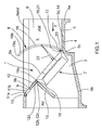
figure 1 est une vue schématique en coupe par un plan vertical longitudinal d'une centrale hydraulique installée dans un ouvrage d'adduction d'eau, dans la configuration où la roue à pales et le carter de l'ensemble à turbine sont en position descendante immergée, où la grille est dans la position érigée, et où le clapet est dans la position érigée de fermeture, de sorte que la centrale hydraulique peut produire de l'électricité par suite du passage du flux d'eau dans la roue à pales de la turbine, des débris étant arrêtés du côté amont de la grille de l'ensemble à grille. - La
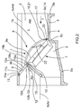
figure 2 est une vue schématique analogue à lafigure 1 , dans la configuration où la roue à pales et le carter de l'ensemble à turbine sont en position descendante immergée, où la grille est dans la position rabattue, et où le clapet est dans la position rabattue d'ouverture, de sorte que le bord transversal supérieur de la grille est situé au niveau de l'ouverture de clapet qui assure une fonction de chasse de débris flottants arrêtés par la grille, vers l'aval du clapet et via l'ouverture de clapet, sans que les débris évacués ne traversent la roue à pales.
- The
figure 1 is a diagrammatic sectional view through a longitudinal vertical plane of a hydraulic power plant installed in a water supply structure, in the configuration where the impeller and the casing of the turbine assembly are in submerged downward position, where the grid is in the erected position, and where the valve is in the erect closing position, so that the hydraulic power station can produce electricity as a result of the flow of water in the impeller wheel of the turbine , debris being stopped on the upstream side of the gate of the grid assembly. - The
figure 2 is a schematic view similar to thefigure 1 in the configuration where the impeller and the turbine assembly casing are in a submerged downward position, where the grate is in the folded position, and the flapper is in the folded open position, so that the upper transverse edge of the gate is located at the valve opening which provides a floating debris flush function stopped by the gate, downstream of the valve and via the valve opening, without the debris evacuated do not cross the paddle wheel.
On se réfère plus spécialement aux
L'ouvrage d'adduction d'eau 2 inclut un canal 3 d'écoulement d'un flux d'eau F et une structure 4 ayant un radier ou fond 5 et deux murs formant bajoyers 6.The
La description qui suit est faite en référence au cas où la centrale hydraulique 1 est montée en situation dans l'ouvrage d'adduction d'eau 2. Toutefois, l'invention vise également le cas où la centrale hydraulique 1, ou des ensembles ou parties de celle-ci, n'est pas montée en situation dans l'ouvrage d'adduction d'eau 2.The description which follows is made with reference to the case where the hydraulic unit 1 is mounted in a situation in the
Les termes tels que « supérieur », « inférieur », « haut », « bas », « au-dessus », « au niveau », « érigé », « rabattu », « incliné », « amont », « aval », « horizontal », « vertical », doivent être compris en relation avec la disposition où la centrale hydraulique 1 est montée en situation dans l'ouvrage d'adduction d'eau 2.Terms such as "superior", "lower", "high", "low", "above", "level", "erected", "folded", "inclined", "upstream", "downstream" , "Horizontal", "vertical", must be understood in relation to the arrangement where the hydraulic unit 1 is mounted in a situation in the
On désigne conventionnellement par « longitudinal » ce qui s'étend dans la direction du canal 3 et par « transversal » ce qui s'étend en travers du canal 3. Il est entendu que les termes « longitudinal », « transversal », « horizontal », « vertical » ne doivent pas en général être interprétés de façon totalement stricte et étroite.The term "longitudinal" conventionally designates that which extends in the direction of the
Le canal 3 a par exemple en section transversale une forme générale de U ou de pseudo-U. L'écoulement du flux d'eau F intervient dans le sens allant de l'amont AM à l'aval AV.The
Le radier 5 est typiquement plan et généralement horizontal ou légèrement incliné sur l'horizontale. Il comporte dans la réalisation représentée une partie amont 5a et une partie aval 5b située à un niveau plus bas que la partie amont, un décrochement 5c vers le bas reliant la partie amont 5a à la partie aval 5b.The
Les deux murs formant bajoyers 6 sont typiquement verticaux ou sensiblement verticaux et parallèles entre eux.The two walls forming bajoyers 6 are typically vertical or substantially vertical and parallel to each other.
On définit encore par NAM le niveau nominal de l'eau vers l'amont AM et par NAV le niveau nominal de l'eau vers l'aval AV.NAM is still defined as the nominal water level upstream AM and NAV as the nominal water level downstream AV.
Le flux d'eau F est par exemple le flux d'un cours d'eau ou d'une dérivation d'un cours d'eau. De façon typique, le flux d'eau arrivant du côté amont peut charrier vers l'aval des débris solides tels que des débris végétaux (feuilles, branches, plantes... par exemple), des débris animaux (animaux morts par exemple), des débris de toute autre sorte (des détritus, des déchets, des emballages.... par exemple). Le terme « débris » doit être considéré dans son acceptation la plus générique. Ces débris sont de taille plus ou moins régulière ou irrégulière et d'une taille plus ou moins grande.The flow of water F is for example the flow of a watercourse or a diversion of a watercourse. Typically, the flow of water arriving from the upstream side can carry down solid debris such as plant debris (leaves, branches, plants ... for example), animal debris (dead animals for example), debris of any other kind (rubbish, garbage, packaging, etc.). The term "debris" should be considered in its most generic acceptance. These debris are of a more or less regular or irregular size and of a larger or smaller size.
La centrale hydraulique 1 comprend, associés fonctionnellement l'un avec l'autre, à savoir, en aval, un ensemble à turbine 7 spécifique et, en amont, un ensemble à grille d'admission du flux d'eau 8. L'un et l'autre sont aptes et destinés à être installés dans et à travers le canal 3.The hydraulic unit 1 comprises, functionally associated with each other, namely, downstream, a
Il est entendu que l'invention vise aussi le cas où la centrale hydraulique 1 comprend plusieurs ensembles à turbine 7 et/ou plusieurs ensembles à grille 8, disposés côte à côte dans le canal 3.It is understood that the invention is also aimed at the case where the hydraulic unit 1 comprises
Un tel ensemble à turbine 7 est du type général décrit dans le document
Un tel ensemble à turbine 7 inclut une structure portante 9 et une turbine à roue à pales montée dans un carter 10 ayant une forme de cylindre plat avec une ouverture du côté amont et une ouverture du côté aval. La structure portante 9 s'étend dans un plan qui est le plan principal de l'ensemble à turbine 7, ou qui est parallèle au plan principal de l'ensemble à turbine 7.Such a
La turbine est par exemple de type KAPLAN et, en tout état de cause, les pales sont montées de sorte à pouvoir être inclinées plus ou moins autour d'axes radiaux, la roue à pales étant plus ou moins ouverte ou plus ou moins fermée.The turbine is for example KAPLAN type and, in any case, the blades are mounted so as to be inclined more or less around radial axes, the paddle wheel being more or less open or more or less closed.
La structure portante 9 comporte une partie principale 9a où est situé le carter 10 et une partie supérieure 9b prolongeant la partie principale 9a vers le haut. La partie principale 9a est fermée à l'exception de la zone en regard des ouvertures du carter 10. La partie supérieure 9b comprend deux bras latéraux 11 a de part et d'autre d'une ouverture 11 b, nonobstant un clapet 12.The supporting
Dans la réalisation représentée, les bras latéraux 11a sont, à leurs parties extrêmes supérieures, montés de manière à pouvoir pivoter autour d'un axe transversal supérieur 13. Ainsi, la roue à pales et le carter 10 sont agencés de sorte à être aptes et destinés à être disposés dans l'une ou l'autre de deux positions, une position descendante immergée dans la canal 3, pour une fonction de production électrique (
Le bord transversal inférieur 14 de la partie principale 9a, et donc de l'ensemble à turbine 7, et ce faisant de sa structure portante 9, est, dans la position descendante immergée, proche du radier 5 ou adjacent à lui. En particulier, le bord transversal inférieur 14 vient reposer sur un siège transversal 5d ménagé vers le décrochement 5c.The lower
Le siège 5d et l'axe 13 sont disposés décalés en direction longitudinale, le premier vers le côté amont AM et le second vers le côté aval AV, de sorte que le plan principal de l'ensemble à turbine 7 dans la position descendante immergée est incliné d'amont en aval et du bas vers le haut avec un angle compris entre 35° et 60°.The
L'ensemble à turbine 7 est équipé du côté amont et en regard de l'ouverture du carter 10 d'une grille d'admission du flux d'eau F (non représentée) apte et destinée à arrêter par son côté amont des débris véhiculés par le flux d'eau F d'une taille supérieure à celle des passages qu'elle comporte. Dans une telle réalisation, l'ensemble à grille 8 peut être qualifié d'ensemble à pré-grille 8.The
En outre, dans une réalisation possible, l'ensemble à turbine 7 est équipé du côté amont d'un dégrilleur (non représenté), en particulier d'un dégrilleur rotatif, associé à la grille d'admission de l'ensemble à turbine 7.Furthermore, in one possible embodiment, the
Dans la réalisation représentée, il est également prévu le clapet 12, lequel fait partie d'un ensemble à clapet ayant également une ouverture de clapet 12a venant en prolongement vers le bas de l'ouverture 11 b.In the embodiment shown, there is also provided the
Le clapet 12 est localisé de sorte à être adjacent à et au-dessus de la partie supérieure 10a du bord du carter 10. Le clapet 12 est apte et destiné à être disposé dans et à travers le canal 3.The
Le clapet 12 est apte et destiné à être disposé dans l'une ou l'autre de deux positions. Dans une position érigée de fermeture (
Dans une position rabattue d'ouverture (
Il est prévu également des moyens d'association du clapet 12 à une structure, telle que, dans la réalisation représentée, la structure portante 9 de l'ensemble à turbine 7, l'ensemble à clapet 12, 12a et l'ensemble à turbine 7 étant alors associés entre eux structurellement. Les moyens d'association du clapet 12 ont une structure propre à permettre le déplacement du clapet 12a de sorte qu'il soit apte et destiné à être disposé dans l'une ou l'autre de ses deux positions érigée de fermeture et rabattue d'ouverture.It is also provided means for associating the
Les moyens d'association du clapet 12 ont une structure, en particulier du type comprenant un arbre monté dans un palier, propre à permettre le pivotement du clapet 12 autour d'un axe 12b disposé transversalement, en particulier vers le bord transversal inférieur 12c du clapet, vers le bord de la partie supérieure 10a du carter 10, en particulier sur une course angulaire entre la position érigée de fermeture et la position rabattue d'ouverture, comprise entre de l'ordre de 50° à 90°.The association means of the
Il est prévu également des moyens de déplacement et de maintien du clapet 12 qui, responsifs à une commande ou à des moyens de commande, sont aptes et destinés à déplacer le clapet 12 entre l'une et l'autre de ses deux positions et de le maintenir dans l'une ou l'autre de ses deux positions. Ces moyens de déplacement et de maintien du clapet 12 sont choisis par exemple dans la gamme comprenant des moyens de déplacement linéaire tels qu'un vérin, ou des moyens de déplacement rotatif tels qu'un moteur rotatif, ou des moyens manuels.It is also provided means for moving and maintaining the
Dans la réalisation représentée, il est également prévu une paroi de séparation et de déflection 15 qui s'étend vers l'aval de l'ensemble à turbine 7 et de l'ensemble à clapet 12, 12a. Cette paroi de séparation et de déflection 15 est disposée entre le bord de la partie supérieure 10a du carter 10 et le bord transversal inférieur 12d de l'ouverture de clapet 12a. Ainsi, l'on peut séparer les flux d'eau respectifs qui traversent le carter 10 et l'ouverture de clapet 12a. Cette paroi de séparation et de détection 15 est ici inclinée d'amont en aval et de haut en bas.In the embodiment shown, there is also provided a partition wall and
L'ensemble à grille (ou à pré-grille, comme précédemment indiqué) 8 inclut en premier lieu une grille à proprement parler 16, laquelle peut être disposée dans et à travers le canal 3. Il inclut en deuxième lieu une structure portante 17 de la grille 15.The grid (or pre-grid, as previously indicated)
La grille 16 comporte des parties pleines qui peuvent être typiquement des barreaux, en particulier régulièrement espacés, s'étendant généralement parallèlement les uns aux autres dans une direction apte à être érigée. Elle comporte également des passages libres. Dans le cas où l'ensemble à turbine 7 est équipé d'une grille d'admission du flux d'eau comme précédemment indiqué, ses passages sont d'une taille plus petite que la taille des passages de la grille 16 de l'ensemble à grille 8.The
Il est prévu également des moyens d'association 18 de la grille 16 à la structure portante 9 de l'ensemble à turbine 7, dans la réalisation représentée sur les figures. Mais, dans d'autres réalisations envisageables, les moyens d'association 18 de la grille 16 sont associés alternativement ou cumulativement à la structure 4 de l'ouvrage d'adduction d'eau 2.It is also provided association means 18 of the
Les moyens d'association 18 de la grille 15 ont une structure propre à permettre le déplacement d'au moins la portion supérieure de la grille 16 opposée au radier 5 de sorte qu'elle soit apte et destinée à être disposée dans l'une ou l'autre de deux positions possibles : une position érigée (
Dans sa position érigée, la grille 16 est érigée de sorte qu'elle intersecte le canal 3 pour que la totalité du flux d'eau qui y circule la traverse, du côté amont AM au côté aval AV. Dans cette position, la grille 16 assure une fonction d'arrêt de débris, arrêtant par son côté amont les débris véhiculés par le flux d'eau d'une taille supérieure à celle des passages qu'elle comporte. Pour cette fonction, le clapet 12, en position érigée de fermeture, assure sa fonction de fermeture. Ainsi, la totalité du flux d'eau ayant préalablement traversé l'ensemble à grille 8 et exempt des débris arrêtés par celui-ci traverse la roue à pales de l'ensemble à turbine 7, sans pouvoir traverser l'ouverture de clapet 12a fermée par le clapet 12.In its erected position, the
Dans sa position rabattue, la grille 16 est moins inclinée sur l'horizontale et assure une fonction d'évacuation de débris flottants qui ont été arrêtés par la grille 16. Ces débris sont évacués vers l'aval de la grille16 en passant par-dessus son bord transversal supérieur 19a, lequel bord transversal supérieur 19a est situé au niveau de l'ouverture de clapet 12a, alors ouverte étant donné que le clapet 12 est dans sa position rabattue d'ouverture, tandis que la partie supérieure 19b de la grille 16, attenante au bord 19a est située au-dessus, et en particulier au moins légèrement en aval, du bord de la partie supérieure 10a du carter 10. Ainsi, l'ouverture de clapet 12a assure une fonction de chasse de débris flottants arrêtés par la grille 16, vers l'aval du clapet 12 et via l'ouverture de clapet 12a, sans que les débris évacués ne traversent la roue à pales, compte tenu de la présence et de la disposition de la paroi de séparation et de déflection 15.In its folded position, the
Il a été constaté que l'évacuation et chasse de débris qui vient d'être exposée est facilitée si les pales de la roue à pales sont amenées dans une position où elles tendent à fermer le passage du flux d'eau, ce qui est rendu possible par la mise en oeuvre d'une roue à pales déplaçables comme il a été indiqué.It has been found that the evacuation and flushing of debris that has just been exposed is facilitated if the blades of the impeller are brought into a position where they tend to close the passage of the flow of water, which is rendered possible by the implementation of a movable paddle wheel as has been indicated.
Dans la réalisation représentée sur les figures, l'ensemble à grille 8 et l'ensemble à turbine 7 sont disposés au voisinage l'un de l'autre, en particulier de façon adjacente, et associés entre eux structurellement pour former un tout, les moyens d'association 18 de la grille 16 étant alors associés à la structure portante 9 de l'ensemble à turbine 7, comme précédemment indiqué.In the embodiment shown in the figures, the
Dans une autre réalisation non représentée, l'ensemble à grille et l'ensemble à turbine sont dissociés structurellement l'un de l'autre. Les moyens d'association de la grille sont alors associés à la structure de l'ouvrage d'adduction d'eau ou à la structure portante de l'ensemble à turbine.In another embodiment not shown, the grid assembly and the turbine assembly are structurally dissociated from each other. The association means of the grid are then associated with the structure of the water supply structure or the supporting structure of the turbine assembly.
L'invention a pour objet aussi bien la centrale hydraulique 1 comportant l'ensemble à grille 8 et l'ensemble à turbine 7 associés entre eux structurellement pour former un tout, que l'ensemble à grille 8 seul en tant qu'il est apte et destiné à être associé structurellement à l'ensemble à turbine 7 ou qu'il est destiné à être structurellement dissocié de l'ensemble à turbine 7, mais associé fonctionnellement à lui dans la centrale hydraulique en situation.The object of the invention is also the hydraulic unit 1 comprising the
La description qui suit porte plus spécialement sur la réalisation dans laquelle l'ensemble à grille 8 et l'ensemble à turbine 7 sont associés entre eux structurellement pour former un tout. La réalisation dans laquelle les deux ensembles 7 et 8 sont dissociés est à la portée de l'homme du métier.The following description relates more particularly to the embodiment in which the
Comme indiqué, les positions érigée et rabattue concernent au moins la portion supérieure de la grille 16. Dans la réalisation représentée sur les figures, ces positions concernent la grille 16 elle-même qui forme un tout solide, déplacé dans son ensemble et disposé dans son ensemble dans l'une ou l'autre des deux positions érigée et rabattue. La description qui suit porte plus spécialement sur cette réalisation. La réalisation dans laquelle seule la portion supérieure de la grille 16 est disposée dans l'une ou l'autre des deux positions émergée et rabattue est à la portée de l'homme du métier.As indicated, the erected and folded positions concern at least the upper portion of the
Dans la réalisation où la grille 16 forme un tout solide, comme représenté sur les figures, les moyens d'association 18 de la grille 16 ont une structure propre à permettre le pivotement de la grille 16 dans son ensemble, autour d'un axe 20 disposé transversalement, proche du, ou adjacent au, radier 5. Dans une réalisation la course angulaire entre la position érigée et la position rabattue de la grille 16 est comprise entre de l'ordre de 35° à 55°.In the embodiment where the
Dans la réalisation représenté sur les figures, la grille 16 est associée à pivotement à l'ensemble à turbine 7, et plus spécialement à sa structure portante 9, autour de l'axe 20 proche des, ou adjacent aux, bord transversal inférieur 21 de l'ensemble à grille 8, donc de la grille 16, et bord transversal inférieur 14 de l'ensemble à turbine 7, donc de la structure portante 9. En outre, les moyens d'association 18 de la grille 16 sont associés à la structure portante 9 de l'ensemble à turbine 7. Dans cette réalisation, le bord transversal inférieur 21 de l'ensemble à grille 8 et le bord transversal inférieur 14 de l'ensemble à turbine 7 sont proches l'un de l'autre, en particulier sont adjacents. Dans cette réalisation, la grille 16 est déplacée également avec le carter 10 de l'ensemble à turbine 7, lorsque celui-ci est agencé de façon mobile entre la position descendante immergée et la position relevée émergée.In the embodiment shown in the figures, the
Les moyens d'association 18 de la grille 17, qui permettent son pivotement entre les positions érigée et rabattue ont par exemple une structure du type comprenant un arbre monté dans un palier.The association means 18 of the
Le plan principal de l'ensemble à turbine 7 et le plan défini par les bords transversaux supérieur et inférieur 19a et 21 de l'ensemble à grille 8 s'étendent dans un ou des plans, en particuliers voisins, inclinés d'amont en aval et du bas vers le haut avec un angle compris entre 35° et 60°.The main plane of the
L'ensemble à grille comporte des moyens de déplacement et de maintien 22 de la grille 16 qui, responsifs à une commande ou à des moyens de commande, sont aptes et destinés à déplacer la grille 16 entre l'une et l'autre de ses deux positions érigée et rabattue et de la maintenir dans l'une ou l'autre de ses deux positions. De tels moyens de déplacement et de maintien 22 de la grille 16 sont par exemple choisis dans la gamme comprenant des moyens de déplacement linéaire tels qu'un vérin, ou des moyens de déplacement rotatif, tels qu'un moteur rotatif, ou des moyens manuels. Ici, les moyens de déplacement et de maintien 22 sont interposés entre la structure portante 9 de l'ensemble à turbine 7 et la grille 16.The grid assembly comprises means for moving and holding 22 of the
Dans la réalisation représentée sur les figures, la grille 16 est incurvée de façon constante ou plus ou moins constante, de sorte que sa convexité soit tournée vers l'amont et à l'opposé de l'ensemble à turbine 7 et que sa concavité soit tournée vers l'aval et vers l'ensemble à turbine 7. Dans la position érigée de la grille 16, le plan moyen de la grille 16 est disposé de sorte à être vertical ou proche de la verticale. De façon générale, dans la position érigée, la grille 16 saille au dessus du niveau nominal amont NAM, et même par exemple au-dessus du canal 3, comme cela est visible sur la
Le rayon de courbure et le centre de courbure de la grille 16 sont tels que, dans la position rabattue de la grille 16, la partie supérieure 19b de la grille 16 soit horizontale ou faiblement inclinée sur l'horizontale, en venant juste au-dessus du bord de la partie supérieure 10a du carter 10, du bord transversal inférieur 12d de l'ouverture de clapet 12a, et du clapet 12 alors en position rabattue d'ouverture. Le bord transversal supérieur 19a de la grille 16 vient se placer en partie inférieure de l'ouverture de clapet 12a.The radius of curvature and the center of curvature of the
Dans une réalisation, il est prévu des moyens d'asservissement des moyens de déplacement et de maintien 22 de la grille 16 et des moyens de déplacement et de maintien du clapet 12 ou de leurs commandes ou moyens de commande.In one embodiment, there is provided servo means for moving and holding means 22 of the
Dans une réalisation, il est prévu en outre des moyens de détection du degré de colmatage de la grille 16 associés aux moyens d'asservissement des moyens de déplacement et de maintien 22 de la grille, aux moyens de déplacement et de maintien du clapet 12 ou à leurs moyens de commande. En outre, les moyens de commande des moyens de déplacement du dégrilleur lorsqu'un tel dégrilleur est prévu sont associés aux moyens d'asservissement des moyens de déplacement et de maintien 22 de la grille 16, ou aux moyens de déplacement et de maintien du clapet 12, ou à leurs moyens de commande.In one embodiment, there is further provided means for detecting the degree of clogging of the
Le procédé de mise en oeuvre d'une centrale hydraulique 1 telle qu'elle a été précédemment décrite est le suivant.The method of implementing a hydraulic unit 1 as previously described is as follows.
On part d'une situation où la grille 16 est dans la position érigée et où le clapet 12 est dans la position érigée de fermeture.We start from a situation where the
On fait fonctionner l'ensemble à turbine 7, un flux d'eau le traversant. On peut ainsi produire de l'électricité.The
Lorsque nécessaire ou lorsque souhaité, en particulier lorsque le degré de colmatage de la grille 16 a atteint un certain degré maximum ou pourrait avoir atteint un certain degré maximum, on commande le déplacement de la grille 16 et ainsi on déplace la grille 16 depuis sa position érigée (
D'autre part, on commande le déplacement du clapet 12 et ainsi on déplace le clapet 12 depuis sa position érigée de fermeture pour l'amener dans sa position rabattue d'ouverture.On the other hand, it controls the movement of the
Ainsi, le bord transversal supérieur 19a de la grille 16 est situé au niveau de l'ouverture de clapet 12a et les débris flottants précédemment arrêtés par la grille 16 sont ainsi chassés vers l'aval du clapet 12 et via l'ouverture de clapet 12a, sans qu'ils ne traversent la roue à pales, qui ainsi n'est pas détériorée, le fonctionnement de la turbine n'étant pas perturbé. Selon une réalisation, avec l'amenée de la grille 16 en position rabattue et l'amenée du clapet 12 en position rabattue, on amène les pales de la roue à pales dans une position où elles tendent à fermer le passage du flux d'eau, ce qui est rendu possible par le choix d'une roue à pales dont les pales peuvent être plus ou moins inclinées et ainsi fermer ou ouvrir plus ou moins l'ouverture de la turbine.Thus, the upper
Claims (14)
- Hydro-electric power plant for a civil waterworks (2), such as a civil waterworks which includes a channel (3) and a structure (4) with a bottom slab (5) and side walls, comprising, operatively associated:▪ a downstream turbine unit (7) including:o a supporting structure (9) in or parallel to the main plane of the assembly (7), comprising a closed main portion (9a) in which is located a cylindrical housing (10) with upstream and downstream openings, and an upper portion (9b) with an opening (11b),o and a turbine with impeller, in particular with blades which can be angled to a greater or lesser extent, mounted in the housing (10), which can be in an immersed downward position where the unit (7) is tilted from upstream to downstream and from the bottom toward the top,▪ a grating assembly (8) upstream for allowing the inflow of water, adapted and intended to be installed in and across the channel (3), including:o a grating (16) supported by a supporting structure (17) and which, fulfilling a debris-stopping function, is adapted and intended to stop, on its upstream side, any debris carried by the flow of water that is larger than the openings through the grating,o and means (18) for associating the grating (16) with supporting structure (9) of the turbine unit (7) and/or structure (4) of the civil waterworks (2), adapted and intended for placing the grating (16) in and across the channel (3) in an upright position in order to perform its debris-stopping function so that water free of debris travels through the impeller,characterized in that:▪ the association means (18) have a structure that allows the movement of at least the upper portion of the grating (16) such that it is adapted and intended for placement in one or the other of the upright position and a folded-down position in which its upper portion (19b) is located above, and in particular at least slightly downstream of, the upper portion (10a) of the edge of the housing (10), in order to discharge, in the downstream direction and above said upper edge (19a), the floating debris stopped by the grating (16), without the debris passing through the impeller,▪ the grating assembly (8) comprises grating (16) movement and retention means (22) which, in response to a control or to control means, are adapted and intended to move the grating (16) from one to the other of its two positions and to retain it in one or the other of its two positions.
- Hydro-electric power plant (1) according to claim 1, wherein the grating assembly (8) and the turbine unit (7) are either arranged near one another, in particular adjacent to one another, and structurally associated with each other to form a structural unit, the grating (16) association means (18) then being associated with the supporting structure (9) of the turbine unit (7), or structurally dissociated from one another, the grating (16) association means (18) then being associated with the structure (4) of the civil waterworks (2) or with the supporting structure (9) of the turbine unit (7).
- Hydro-electric power plant (1) according to either of claims 1 and 2, wherein the lower transverse edge (21) of the grating assembly (8) and the lower transverse edge (14) of the turbine unit (7) are close to each other, in particular are adjacent, and in particular are close to, or adjacent to, the bottom slab (5).
- Hydro-electric power plant (1) according to any one of claims 1 to 3, wherein the grating (16) association means (18) have a structure, in particular of the type comprising a shaft mounted in a bearing, suitable to allow at least the upper portion of the grating (16) to pivot about a transverse axis (20).
- Hydro-electric power plant (1) according to any one of claims 1 to 4, wherein the grating (16) form a solid unit, moved as a unit and placed as a unit in one of the two positions, upright or folded down, and wherein the grating (16) association means (18) have a structure allowing the grating (16) to pivot about a transverse axis (20) arranged close or adjacent to the bottom slab (5), in particular following an angular path between the upright position and the folded-down position of about 35° to 55°.
- Hydro-electric power plant (1) according to claim 5, wherein the grating (16) is pivotally associated with the turbine unit (7) so that it pivots about a transverse axis (20) arranged close to or adjacent to the lower transverse edge (21) of the grating assembly (8) and the lower transverse edge (14) of the turbine unit (7), and wherein the grating (16) association means (18) are associated with the supporting structure (9) of the turbine unit (7).
- Hydro-electric power plant (1) according to any one of claims 1 to 6, comprising one and/or the other of the following features:- the grating (16) movement and retention means (22) are selected from among an assortment comprising linear displacement means such as a jack, or rotary displacement means such as a rotary engine, or manual means;- the grating (16) comprises bars, in particular bars regularly spaced apart, in general extending parallel to one another in a direction that can be raised;- the grating (16) is curved with its convexity facing upstream and away from the turbine unit (7) and its concavity facing downstream and towards the turbine unit (7), so that when in the folded-down position, the upper portion (19b) of the grating (16) is adapted and intended to be horizontal or slightly inclined to the horizontal.
- Hydro-electric power plant (1) according to any one of claims 1 to 7, comprising:▪ a flap valve (12) of a flap valve assembly (12, 12a) having a valve opening (12a), which:o is located adjacent to and above the upper portion (10a) of the edge of the impeller housing (10) and in the downstream direction with the upper transverse edge (19a) of the grating (16) in the folded-down position, said upper transverse edge (19a) being level with the valve opening (12a),o is adapted and intended for placement in and across the channel (3),o is adapted and intended for placement in either of two positions, an upright closure position for stopping the incoming flow of water, and a folded-down opening position for allowing said flow of water to pass without passing through the impeller,▪ means for associating the flap valve (12) with the supporting structure (9) of the turbine unit (7) and/or with the supporting structure (17) of the grating (16) and/or with the structure (4) of the civil waterworks (2), having a structure which allows the movement of the flap valve (12) so that it is adapted and intended to be arranged in one of its two upright closure and folded down opening positions,▪ flap valve (12) movement and retention means which, in response to a control or to control means, are adapted and intended to move the flap valve (12) between one and the other of its two positions and to retain it in one or the other of its two positions,▪ and controller means for the grating (16) movement and retention means and for the flap valve (12) movement and retention means or for their controls or control means, such that:o when the grating (16) is in the upright position, the flap valve (12) performs a closure function, being adapted and intended to be in the upright closure position such that the flow of water having previously passed through the grating assembly (8) and free of the debris stopped by said grating assembly passes through the impeller without being able to pass through the valve opening (12a),o and when the grating (16) is in the folded-down position, the upper transverse edge (19a) of the grating (16) is level with the valve opening (12a), which acts to send, downstream of the flap valve (12) and through the valve opening (12a), the floating debris stopped by the grating (16), without the discharged debris passing through the impeller.
- Hydro-electric power plant (1) according to claim 8, comprising one and/or the other of the following features:- the flap valve assembly (12, 12a) and the turbine unit (7) are structurally associated with each other, the flap valve (12) association means being associated with the supporting structure (9) of the turbine unit (7);- the flap valve (12) association means have a structure, particularly of the type comprising a shaft mounted in a bearing, adapted to allow the flap valve (12) to pivot about an axis (12b) arranged transversely, in particular toward the lower transverse edge (12c) of the flap valve (12), toward the upper edge (10a) of the impeller housing (10), and near the upper transverse edge (19a) of the grating (16) in the folded-down position, in particular following an angular path between the upright closure position and the folded-down opening position of about 50° to 90 °;- the flap valve (12) movement and retention means are selected from among an assortment comprising linear displacement means such as a jack, or rotary displacement means such as a rotary engine, or manual means;- the hydro-electric power plant (1) further comprises means for detecting the degree of clogging of the grating (16), said means being associated with the controller means for the grating (16) movement and retention means (22), the flap valve (12) movement and retention means, or their control means;- the main plane of the turbine unit (7), the plane of the flap valve (12) in its upright closure position, and the plane defined by the upper (19a) and lower (21) transverse edges (19a) of the grating assembly (8), lie in one or more planes, in particular adjacent planes, inclined from upstream to downstream and from the bottom toward the top at an angle of between 35° to 60 °;- the hydro-electric power plant (1) further comprises a deflecting and partitioning wall (15) extending downstream from the turbine unit (7) and flap valve assembly (12, 12a), arranged between the upper portion (10a) of the edge (10) of the impeller housing and the lower transverse edge (12d) of the valve opening (12a) so as to separate the flows of water respectively passing through them, said deflecting and partitioning wall (15) being inclined from upstream to downstream and from the top downwards.
- Hydro-electric power plant (1) according to any one of claims 1 to 9, wherein the turbine unit (7) is equipped, on the upstream side and opposite the opening (10) of the impeller housing, with a water intake grating that is adapted and intended to stop, on its upstream side, any debris carried by the water of a size greater than the openings through said grating, these openings being smaller in size than the openings through the grating (16) of the grating assembly (8), which then constitutes a pre-grating assembly.
- Hydro-electric power plant (1) according to claim 10, wherein the turbine unit (7) is equipped on its upstream side with a scraper, particularly a rotating scraper, associated with the intake grating of the turbine unit (7), and wherein the control means for the scraper movement means are associated with the controller means for the grating (16) movement and retention means (22), or the flap valve (12) movement and retention means, or their control means.
- Hydro-electric power plant (1) according to any one of claims 6 to 11 when dependent on claim 6, wherein the impeller and the housing (10) of the turbine unit (7) are arranged so as to be adapted and intended for placement in one of two positions, an immersed downward position for an electricity generation function, and a non-immersed raised position for access to the turbine unit (7) and/or for clearing the water flow channel (3), the grating (16) of the grating assembly (8) also being moved with the housing (10) of the turbine unit (7).
- Method for utilizing a hydro-electric power plant (1) according to any one of claims 8 to 12, for the purposes of discharging the floating debris stopped by the grating (16), wherein:▪ initially the grating (16) is in the upright position and the flap valve (12) is in the upright closure position,▪ the turbine unit (7) is placed in operation, with water flowing through it,▪ when necessary or when desired, particularly when the degree of clogging of the grating (16) has reached a certain maximum degree or may have reached a certain maximum degree:o the grating (16) is told to move and the grating (16) is accordingly moved from its upright position to its folded-down position,o and the flap valve (12) is told to move and the flap valve (12) is accordingly moved from its upright closure position to its folded-down opening position, such that the upper transverse edge of the grating (16) is level with the valve opening (12a), the floating debris stopped by the grating (16) thus being sent downstream of the flap valve (12) and through the valve opening (12a) without passing through the impeller.
- Method according to claim 13, wherein, with the grating (16) placed in the folded-down position and the flap valve (12) placed in the folded-down position, the blades of the impeller are placed in a position where they more or less close off the passage of the stream of water.
Applications Claiming Priority (2)
| Application Number | Priority Date | Filing Date | Title |
|---|---|---|---|
| FR1154257A FR2975444B1 (en) | 2011-05-17 | 2011-05-17 | HYDRAULIC POWER PLANT COMPRISING AN INTAKE GRID ASSEMBLY IN THE TURBINE AGENCY FOR EVACUATING FLOATING DEBRIS ARRANGED BY THE GRID. |
| PCT/FR2012/050788 WO2012156604A1 (en) | 2011-05-17 | 2012-04-11 | Hydro-electric power plant comprising a grating assembly for taking water into the turbine, which is designed to discharge floating debris stopped by the grating |
Publications (2)
| Publication Number | Publication Date |
|---|---|
| EP2710255A1 EP2710255A1 (en) | 2014-03-26 |
| EP2710255B1 true EP2710255B1 (en) | 2016-10-26 |
Family
ID=46147494
Family Applications (1)
| Application Number | Title | Priority Date | Filing Date |
|---|---|---|---|
| EP12722775.9A Not-in-force EP2710255B1 (en) | 2011-05-17 | 2012-04-11 | Hydro-electric power plant comprising a grating assembly for taking water into the turbine, which is designed to discharge floating debris stopped by the grating |
Country Status (8)
| Country | Link |
|---|---|
| US (1) | US9611607B2 (en) |
| EP (1) | EP2710255B1 (en) |
| JP (1) | JP5952389B2 (en) |
| CN (1) | CN103688048B (en) |
| BR (1) | BR112013029594A2 (en) |
| CA (1) | CA2836350C (en) |
| FR (1) | FR2975444B1 (en) |
| WO (1) | WO2012156604A1 (en) |
Families Citing this family (6)
| Publication number | Priority date | Publication date | Assignee | Title |
|---|---|---|---|---|
| DE102014226682B3 (en) * | 2014-12-19 | 2016-06-23 | Siemens Aktiengesellschaft | Underwater turbine for converting hydrodynamic energy into electrical energy and method for cleaning an underwater turbine |
| US10997258B2 (en) * | 2018-02-28 | 2021-05-04 | Fujitsu Limited | Bot networks |
| WO2019200128A1 (en) * | 2018-04-11 | 2019-10-17 | BVH, Inc. | Modular hydropower unit |
| CN109032098B (en) * | 2018-08-28 | 2021-04-09 | 云南电网有限责任公司电力科学研究院 | Method for analyzing full-working-condition single-parameter degradation trend of hydroelectric generating set |
| CA3077753A1 (en) * | 2019-04-12 | 2020-10-12 | Cameron Farms Hutterite Colony | Fluid pumping apparatus and methods of use |
| US11066798B2 (en) * | 2019-06-13 | 2021-07-20 | Sea To Sky Energy Solutions Corp. | Water intake structure |
Family Cites Families (27)
| Publication number | Priority date | Publication date | Assignee | Title |
|---|---|---|---|---|
| US1606546A (en) * | 1926-11-09 | Hydraulic plant and screen thbrefqe | ||
| US1411945A (en) * | 1920-09-11 | 1922-04-04 | Frank O Wallene | Hydraulic apparatus |
| US1586754A (en) * | 1925-03-23 | 1926-06-01 | Morgan Smith S Co | Double rack for water supply |
| DE759178C (en) * | 1939-12-17 | 1953-08-17 | Arno Fischer | Floodable underwater power plant for rivers |
| US4319142A (en) * | 1980-09-25 | 1982-03-09 | Allis-Chalmers Corporation | Power generation unit for spillway gate structures |
| FR2531118A1 (en) * | 1982-07-30 | 1984-02-03 | Durafour Construction | Hydraulic barrage element and processes for installing it. |
| US4415462A (en) * | 1982-08-12 | 1983-11-15 | Finch Harvey E | Self-cleaning screen |
| US4804855A (en) * | 1987-02-13 | 1989-02-14 | Obermeyer Henry K | Hydromotive machine apparatus and method of constructing the same |
| JPH09112495A (en) * | 1995-10-13 | 1997-05-02 | Mitsubishi Heavy Ind Ltd | Screen device |
| US5954474A (en) * | 1996-03-28 | 1999-09-21 | Voith Hydro, Inc. | Hydro-turbine runner |
| US5754446A (en) * | 1996-08-19 | 1998-05-19 | Voith Hydro, Inc. | Method and apparatus for optimizing performance of a kaplan turbine |
| US6281597B1 (en) * | 1999-08-13 | 2001-08-28 | Syndicated Technologies, Llc. | Hydroelectric installation and method of constructing same |
| AT4390U1 (en) * | 2000-03-31 | 2001-06-25 | Steiner Reinhard Dipl Ing | METHOD FOR DETERMINING THE NET HEIGHT OF TURBINES |
| AT409505B (en) * | 2000-04-28 | 2002-09-25 | Hans Kuenz Ges M B H | CALCULATION CLEANING EQUIPMENT |
| AT411369B (en) * | 2001-12-20 | 2003-12-29 | Va Tech Hydro Gmbh & Co | METHOD FOR PRODUCING A HYDROPOWER PLANT |
| FR2835548B1 (en) | 2002-02-06 | 2004-04-30 | Cocguen Marie Louise Le | ARTICULATED LINEAR MODULE FOR DESOBSTRUCTION OF LIQUID INTAKE GRID CONTAINING WASTE |
| DE10231744A1 (en) * | 2002-07-13 | 2004-01-22 | Hermann Henkel | Hinged water barrier has turbine for generating current in chamber behind barrier wall, inlet aperture below upper water level to which operating water channel leading to turbine chamber is connected |
| US6864596B2 (en) * | 2002-10-07 | 2005-03-08 | Voith Siemens Hydro Power Generation, Gmbh & Co. Kg | Hydrogen production from hydro power |
| AT413425B (en) * | 2003-03-06 | 2006-02-15 | Va Tech Hydro Gmbh & Co | DEVICE FOR GENERATING ELECTRICAL ENERGY |
| FR2862723B1 (en) * | 2003-11-20 | 2006-04-28 | Jacques Fonkenell | TURBINE AND HYDRAULIC POWER PLANT FOR VERY LOW FALL |
| FR2865226B1 (en) * | 2004-01-19 | 2007-04-13 | Cismac Electronique | PREFABRICATED MODULAR HYDROELECTRIC DAM INCORPORATING ALL OR PART OF THE HYDRAULIC AND ELECTRICAL EQUIPMENT NECESSARY FOR ITS OPERATION. |
| FR2874334B1 (en) * | 2004-08-20 | 2006-11-24 | Beaudrey Et Cie Sa E | ROTARY SIEVE FOR WATER TAKING |
| CA2531708A1 (en) * | 2005-04-15 | 2006-10-15 | Edouard Petrounevitch | Modular system for generating electricity from moving fluid |
| JP2007187083A (en) * | 2006-01-13 | 2007-07-26 | Shinko Electric Co Ltd | Small scale hydraulic power generation device |
| DE102010018806A1 (en) * | 2010-04-29 | 2011-11-03 | Voith Patent Gmbh | Flusskraftwerk |
| US20100327586A1 (en) * | 2010-05-28 | 2010-12-30 | Technology Patents, Llc | Drainage, filtration, and electricity generating systems and methods |
| US20120187692A1 (en) * | 2011-01-21 | 2012-07-26 | Walton Randal D | Hydroelectric generators |
-
2011
- 2011-05-17 FR FR1154257A patent/FR2975444B1/en not_active Expired - Fee Related
-
2012
- 2012-04-11 BR BR112013029594A patent/BR112013029594A2/en active Search and Examination
- 2012-04-11 CN CN201280035073.3A patent/CN103688048B/en not_active Expired - Fee Related
- 2012-04-11 EP EP12722775.9A patent/EP2710255B1/en not_active Not-in-force
- 2012-04-11 CA CA2836350A patent/CA2836350C/en not_active Expired - Fee Related
- 2012-04-11 US US14/117,971 patent/US9611607B2/en active Active
- 2012-04-11 WO PCT/FR2012/050788 patent/WO2012156604A1/en active Application Filing
- 2012-04-11 JP JP2014510853A patent/JP5952389B2/en not_active Expired - Fee Related
Non-Patent Citations (1)
| Title |
|---|
| None * |
Also Published As
| Publication number | Publication date |
|---|---|
| FR2975444A1 (en) | 2012-11-23 |
| CN103688048A (en) | 2014-03-26 |
| CA2836350C (en) | 2018-08-28 |
| US9611607B2 (en) | 2017-04-04 |
| WO2012156604A1 (en) | 2012-11-22 |
| JP2014513777A (en) | 2014-06-05 |
| FR2975444B1 (en) | 2016-12-23 |
| EP2710255A1 (en) | 2014-03-26 |
| JP5952389B2 (en) | 2016-07-13 |
| US20140102989A1 (en) | 2014-04-17 |
| CN103688048B (en) | 2017-03-15 |
| CA2836350A1 (en) | 2012-11-22 |
| BR112013029594A2 (en) | 2017-03-21 |
Similar Documents
| Publication | Publication Date | Title |
|---|---|---|
| EP2710255B1 (en) | Hydro-electric power plant comprising a grating assembly for taking water into the turbine, which is designed to discharge floating debris stopped by the grating | |
| EP2307711B1 (en) | Inlet device for environmentally-friendly hydraulic turbine machine | |
| WO2005054667A2 (en) | Turbine and hydroelectric power plant for very low drops | |
| EP3173529B1 (en) | Snow stirring device | |
| EP3061891A1 (en) | Discharging mechanism for a concrete bucket comprising a receptacle for the leakage of the laitance | |
| WO2004048773A1 (en) | Hydraulic wheel | |
| FR2946062A1 (en) | Materials separator device for use in waste water pumping station, has flap associated to supply pipe connected to pump cooperating along bottom edge with seat delimited or carried by corresponding vertical wall | |
| EP2888414B1 (en) | Automatic adjustable valve | |
| EP1441125A1 (en) | Hydraulic turbine with siphon action | |
| FR2531118A1 (en) | Hydraulic barrage element and processes for installing it. | |
| CA3056705A1 (en) | Device for producing hydro-electric power | |
| EP3633185B1 (en) | Bucket intended to equip a water wheel of a hydrokinetic machine | |
| FR3138672A1 (en) | HYDROELECTRIC POWER PLANT | |
| FR2730509A1 (en) | Floating barrage for recovery of current driven floating waste, esp. solid bodies | |
| FR2843312A1 (en) | Surface water decantation plant has hydraulic distributor with deflector and adjustable partition forming inlet slit extending across tank width | |
| WO2007093416A1 (en) | Very low-head hydroelectric plant | |
| FR2891286A1 (en) | Water barrage sluice gate has hinge at lower end and contains turbine to generate electricity from overflow | |
| FR2982347A1 (en) | Apparatus for collecting and discharging dust generated from e.g. interior work, in boundary area, has box forming suction opening on lateral side and including wooden frame on lateral side, where seat completely surrounds suction opening | |
| FR3107637A1 (en) | Device for the methanization of organic matter | |
| WO2013098494A1 (en) | Hydraulic turbine intended, in particular, for a tidal power plant | |
| FR2553803A1 (en) | Automatic screen-cleaning machine | |
| FR2998311A1 (en) | Water supply installation for hydraulic generator that is utilized for facilitating e.g. maintenance of screen cleaner for cleaning waste storage grid, has diversion canal whose end is arranged on level of outlet conduit of energy generator | |
| EP3012374A1 (en) | Screen rake with floating beam | |
| CH223732A (en) | Hydraulic grid. | |
| FR2995032A1 (en) | Hydroelectric barrier for controlling water flow in waterway for production of electrical energy, has hydraulic apparatus whose box is supported in water, and vertical valve fixed under pin for occupying width of passage between walls |
Legal Events
| Date | Code | Title | Description |
|---|---|---|---|
| PUAI | Public reference made under article 153(3) epc to a published international application that has entered the european phase |
Free format text: ORIGINAL CODE: 0009012 |
|
| 17P | Request for examination filed |
Effective date: 20131206 |
|
| AK | Designated contracting states |
Kind code of ref document: A1 Designated state(s): AL AT BE BG CH CY CZ DE DK EE ES FI FR GB GR HR HU IE IS IT LI LT LU LV MC MK MT NL NO PL PT RO RS SE SI SK SM TR |
|
| DAX | Request for extension of the european patent (deleted) | ||
| REG | Reference to a national code |
Ref country code: DE Ref legal event code: R079 Ref document number: 602012024572 Country of ref document: DE Free format text: PREVIOUS MAIN CLASS: F03B0011080000 Ipc: E02B0009040000 |
|
| RIC1 | Information provided on ipc code assigned before grant |
Ipc: E02B 5/08 20060101ALI20160310BHEP Ipc: E02B 9/04 20060101AFI20160310BHEP Ipc: F03B 11/08 20060101ALI20160310BHEP Ipc: F03B 3/04 20060101ALI20160310BHEP Ipc: F03B 13/08 20060101ALI20160310BHEP Ipc: F03B 3/14 20060101ALI20160310BHEP Ipc: E02B 8/02 20060101ALI20160310BHEP |
|
| GRAP | Despatch of communication of intention to grant a patent |
Free format text: ORIGINAL CODE: EPIDOSNIGR1 |
|
| INTG | Intention to grant announced |
Effective date: 20160510 |
|
| GRAJ | Information related to disapproval of communication of intention to grant by the applicant or resumption of examination proceedings by the epo deleted |
Free format text: ORIGINAL CODE: EPIDOSDIGR1 |
|
| GRAR | Information related to intention to grant a patent recorded |
Free format text: ORIGINAL CODE: EPIDOSNIGR71 |
|
| GRAS | Grant fee paid |
Free format text: ORIGINAL CODE: EPIDOSNIGR3 |
|
| GRAA | (expected) grant |
Free format text: ORIGINAL CODE: 0009210 |
|
| INTC | Intention to grant announced (deleted) | ||
| AK | Designated contracting states |
Kind code of ref document: B1 Designated state(s): AL AT BE BG CH CY CZ DE DK EE ES FI FR GB GR HR HU IE IS IT LI LT LU LV MC MK MT NL NO PL PT RO RS SE SI SK SM TR |
|
| INTG | Intention to grant announced |
Effective date: 20160921 |
|
| REG | Reference to a national code |
Ref country code: GB Ref legal event code: FG4D Free format text: NOT ENGLISH |
|
| REG | Reference to a national code |
Ref country code: CH Ref legal event code: EP |
|
| REG | Reference to a national code |
Ref country code: AT Ref legal event code: REF Ref document number: 840140 Country of ref document: AT Kind code of ref document: T Effective date: 20161115 |
|
| REG | Reference to a national code |
Ref country code: IE Ref legal event code: FG4D Free format text: LANGUAGE OF EP DOCUMENT: FRENCH |
|
| REG | Reference to a national code |
Ref country code: DE Ref legal event code: R096 Ref document number: 602012024572 Country of ref document: DE |
|
| REG | Reference to a national code |
Ref country code: LT Ref legal event code: MG4D |
|
| PG25 | Lapsed in a contracting state [announced via postgrant information from national office to epo] |
Ref country code: LV Free format text: LAPSE BECAUSE OF FAILURE TO SUBMIT A TRANSLATION OF THE DESCRIPTION OR TO PAY THE FEE WITHIN THE PRESCRIBED TIME-LIMIT Effective date: 20161026 |
|
| REG | Reference to a national code |
Ref country code: NL Ref legal event code: MP Effective date: 20161026 |
|
| REG | Reference to a national code |
Ref country code: AT Ref legal event code: MK05 Ref document number: 840140 Country of ref document: AT Kind code of ref document: T Effective date: 20161026 |
|
| REG | Reference to a national code |
Ref country code: FR Ref legal event code: PLFP Year of fee payment: 6 |
|
| PG25 | Lapsed in a contracting state [announced via postgrant information from national office to epo] |
Ref country code: SE Free format text: LAPSE BECAUSE OF FAILURE TO SUBMIT A TRANSLATION OF THE DESCRIPTION OR TO PAY THE FEE WITHIN THE PRESCRIBED TIME-LIMIT Effective date: 20161026 Ref country code: NO Free format text: LAPSE BECAUSE OF FAILURE TO SUBMIT A TRANSLATION OF THE DESCRIPTION OR TO PAY THE FEE WITHIN THE PRESCRIBED TIME-LIMIT Effective date: 20170126 Ref country code: LT Free format text: LAPSE BECAUSE OF FAILURE TO SUBMIT A TRANSLATION OF THE DESCRIPTION OR TO PAY THE FEE WITHIN THE PRESCRIBED TIME-LIMIT Effective date: 20161026 Ref country code: GR Free format text: LAPSE BECAUSE OF FAILURE TO SUBMIT A TRANSLATION OF THE DESCRIPTION OR TO PAY THE FEE WITHIN THE PRESCRIBED TIME-LIMIT Effective date: 20170127 |
|
| PG25 | Lapsed in a contracting state [announced via postgrant information from national office to epo] |
Ref country code: RS Free format text: LAPSE BECAUSE OF FAILURE TO SUBMIT A TRANSLATION OF THE DESCRIPTION OR TO PAY THE FEE WITHIN THE PRESCRIBED TIME-LIMIT Effective date: 20161026 Ref country code: PT Free format text: LAPSE BECAUSE OF FAILURE TO SUBMIT A TRANSLATION OF THE DESCRIPTION OR TO PAY THE FEE WITHIN THE PRESCRIBED TIME-LIMIT Effective date: 20170227 Ref country code: ES Free format text: LAPSE BECAUSE OF FAILURE TO SUBMIT A TRANSLATION OF THE DESCRIPTION OR TO PAY THE FEE WITHIN THE PRESCRIBED TIME-LIMIT Effective date: 20161026 Ref country code: IS Free format text: LAPSE BECAUSE OF FAILURE TO SUBMIT A TRANSLATION OF THE DESCRIPTION OR TO PAY THE FEE WITHIN THE PRESCRIBED TIME-LIMIT Effective date: 20170226 Ref country code: FI Free format text: LAPSE BECAUSE OF FAILURE TO SUBMIT A TRANSLATION OF THE DESCRIPTION OR TO PAY THE FEE WITHIN THE PRESCRIBED TIME-LIMIT Effective date: 20161026 Ref country code: PL Free format text: LAPSE BECAUSE OF FAILURE TO SUBMIT A TRANSLATION OF THE DESCRIPTION OR TO PAY THE FEE WITHIN THE PRESCRIBED TIME-LIMIT Effective date: 20161026 Ref country code: AT Free format text: LAPSE BECAUSE OF FAILURE TO SUBMIT A TRANSLATION OF THE DESCRIPTION OR TO PAY THE FEE WITHIN THE PRESCRIBED TIME-LIMIT Effective date: 20161026 Ref country code: HR Free format text: LAPSE BECAUSE OF FAILURE TO SUBMIT A TRANSLATION OF THE DESCRIPTION OR TO PAY THE FEE WITHIN THE PRESCRIBED TIME-LIMIT Effective date: 20161026 Ref country code: NL Free format text: LAPSE BECAUSE OF FAILURE TO SUBMIT A TRANSLATION OF THE DESCRIPTION OR TO PAY THE FEE WITHIN THE PRESCRIBED TIME-LIMIT Effective date: 20161026 |
|
| REG | Reference to a national code |
Ref country code: DE Ref legal event code: R097 Ref document number: 602012024572 Country of ref document: DE |
|
| PG25 | Lapsed in a contracting state [announced via postgrant information from national office to epo] |
Ref country code: DK Free format text: LAPSE BECAUSE OF FAILURE TO SUBMIT A TRANSLATION OF THE DESCRIPTION OR TO PAY THE FEE WITHIN THE PRESCRIBED TIME-LIMIT Effective date: 20161026 Ref country code: EE Free format text: LAPSE BECAUSE OF FAILURE TO SUBMIT A TRANSLATION OF THE DESCRIPTION OR TO PAY THE FEE WITHIN THE PRESCRIBED TIME-LIMIT Effective date: 20161026 Ref country code: CZ Free format text: LAPSE BECAUSE OF FAILURE TO SUBMIT A TRANSLATION OF THE DESCRIPTION OR TO PAY THE FEE WITHIN THE PRESCRIBED TIME-LIMIT Effective date: 20161026 Ref country code: SK Free format text: LAPSE BECAUSE OF FAILURE TO SUBMIT A TRANSLATION OF THE DESCRIPTION OR TO PAY THE FEE WITHIN THE PRESCRIBED TIME-LIMIT Effective date: 20161026 Ref country code: RO Free format text: LAPSE BECAUSE OF FAILURE TO SUBMIT A TRANSLATION OF THE DESCRIPTION OR TO PAY THE FEE WITHIN THE PRESCRIBED TIME-LIMIT Effective date: 20161026 |
|
| PG25 | Lapsed in a contracting state [announced via postgrant information from national office to epo] |
Ref country code: IT Free format text: LAPSE BECAUSE OF FAILURE TO SUBMIT A TRANSLATION OF THE DESCRIPTION OR TO PAY THE FEE WITHIN THE PRESCRIBED TIME-LIMIT Effective date: 20161026 Ref country code: BG Free format text: LAPSE BECAUSE OF FAILURE TO SUBMIT A TRANSLATION OF THE DESCRIPTION OR TO PAY THE FEE WITHIN THE PRESCRIBED TIME-LIMIT Effective date: 20170126 Ref country code: SM Free format text: LAPSE BECAUSE OF FAILURE TO SUBMIT A TRANSLATION OF THE DESCRIPTION OR TO PAY THE FEE WITHIN THE PRESCRIBED TIME-LIMIT Effective date: 20161026 |
|
| PLBE | No opposition filed within time limit |
Free format text: ORIGINAL CODE: 0009261 |
|
| STAA | Information on the status of an ep patent application or granted ep patent |
Free format text: STATUS: NO OPPOSITION FILED WITHIN TIME LIMIT |
|
| 26N | No opposition filed |
Effective date: 20170727 |
|
| PG25 | Lapsed in a contracting state [announced via postgrant information from national office to epo] |
Ref country code: SI Free format text: LAPSE BECAUSE OF FAILURE TO SUBMIT A TRANSLATION OF THE DESCRIPTION OR TO PAY THE FEE WITHIN THE PRESCRIBED TIME-LIMIT Effective date: 20161026 |
|
| REG | Reference to a national code |
Ref country code: IE Ref legal event code: MM4A |
|
| PG25 | Lapsed in a contracting state [announced via postgrant information from national office to epo] |
Ref country code: MC Free format text: LAPSE BECAUSE OF FAILURE TO SUBMIT A TRANSLATION OF THE DESCRIPTION OR TO PAY THE FEE WITHIN THE PRESCRIBED TIME-LIMIT Effective date: 20161026 |
|
| PG25 | Lapsed in a contracting state [announced via postgrant information from national office to epo] |
Ref country code: LU Free format text: LAPSE BECAUSE OF NON-PAYMENT OF DUE FEES Effective date: 20170411 |
|
| REG | Reference to a national code |
Ref country code: FR Ref legal event code: PLFP Year of fee payment: 7 |
|
| PG25 | Lapsed in a contracting state [announced via postgrant information from national office to epo] |
Ref country code: IE Free format text: LAPSE BECAUSE OF NON-PAYMENT OF DUE FEES Effective date: 20170411 |
|
| PG25 | Lapsed in a contracting state [announced via postgrant information from national office to epo] |
Ref country code: MT Free format text: LAPSE BECAUSE OF FAILURE TO SUBMIT A TRANSLATION OF THE DESCRIPTION OR TO PAY THE FEE WITHIN THE PRESCRIBED TIME-LIMIT Effective date: 20161026 |
|
| PG25 | Lapsed in a contracting state [announced via postgrant information from national office to epo] |
Ref country code: HU Free format text: LAPSE BECAUSE OF FAILURE TO SUBMIT A TRANSLATION OF THE DESCRIPTION OR TO PAY THE FEE WITHIN THE PRESCRIBED TIME-LIMIT; INVALID AB INITIO Effective date: 20120411 |
|
| PG25 | Lapsed in a contracting state [announced via postgrant information from national office to epo] |
Ref country code: CY Free format text: LAPSE BECAUSE OF NON-PAYMENT OF DUE FEES Effective date: 20161026 |
|
| PG25 | Lapsed in a contracting state [announced via postgrant information from national office to epo] |
Ref country code: MK Free format text: LAPSE BECAUSE OF FAILURE TO SUBMIT A TRANSLATION OF THE DESCRIPTION OR TO PAY THE FEE WITHIN THE PRESCRIBED TIME-LIMIT Effective date: 20161026 |
|
| PG25 | Lapsed in a contracting state [announced via postgrant information from national office to epo] |
Ref country code: TR Free format text: LAPSE BECAUSE OF FAILURE TO SUBMIT A TRANSLATION OF THE DESCRIPTION OR TO PAY THE FEE WITHIN THE PRESCRIBED TIME-LIMIT Effective date: 20161026 |
|
| PG25 | Lapsed in a contracting state [announced via postgrant information from national office to epo] |
Ref country code: AL Free format text: LAPSE BECAUSE OF FAILURE TO SUBMIT A TRANSLATION OF THE DESCRIPTION OR TO PAY THE FEE WITHIN THE PRESCRIBED TIME-LIMIT Effective date: 20161026 |
|
| PGFP | Annual fee paid to national office [announced via postgrant information from national office to epo] |
Ref country code: DE Payment date: 20200513 Year of fee payment: 9 Ref country code: CH Payment date: 20200528 Year of fee payment: 9 Ref country code: FR Payment date: 20200429 Year of fee payment: 9 |
|
| PGFP | Annual fee paid to national office [announced via postgrant information from national office to epo] |
Ref country code: GB Payment date: 20200527 Year of fee payment: 9 Ref country code: BE Payment date: 20200429 Year of fee payment: 9 |
|
| REG | Reference to a national code |
Ref country code: DE Ref legal event code: R119 Ref document number: 602012024572 Country of ref document: DE |
|
| GBPC | Gb: european patent ceased through non-payment of renewal fee |
Effective date: 20210411 |
|
| REG | Reference to a national code |
Ref country code: BE Ref legal event code: MM Effective date: 20210430 |
|
| PG25 | Lapsed in a contracting state [announced via postgrant information from national office to epo] |
Ref country code: FR Free format text: LAPSE BECAUSE OF NON-PAYMENT OF DUE FEES Effective date: 20210430 Ref country code: GB Free format text: LAPSE BECAUSE OF NON-PAYMENT OF DUE FEES Effective date: 20210411 Ref country code: DE Free format text: LAPSE BECAUSE OF NON-PAYMENT OF DUE FEES Effective date: 20211103 Ref country code: LI Free format text: LAPSE BECAUSE OF NON-PAYMENT OF DUE FEES Effective date: 20210430 Ref country code: CH Free format text: LAPSE BECAUSE OF NON-PAYMENT OF DUE FEES Effective date: 20210430 |
|
| PG25 | Lapsed in a contracting state [announced via postgrant information from national office to epo] |
Ref country code: BE Free format text: LAPSE BECAUSE OF NON-PAYMENT OF DUE FEES Effective date: 20210430 |