EP2708839B1 - Permanent magnet type cylindrical molten metal stirring device, and melting furnace - Google Patents
Permanent magnet type cylindrical molten metal stirring device, and melting furnace Download PDFInfo
- Publication number
- EP2708839B1 EP2708839B1 EP12868335.6A EP12868335A EP2708839B1 EP 2708839 B1 EP2708839 B1 EP 2708839B1 EP 12868335 A EP12868335 A EP 12868335A EP 2708839 B1 EP2708839 B1 EP 2708839B1
- Authority
- EP
- European Patent Office
- Prior art keywords
- molten
- metal
- room
- driving room
- molten metal
- Prior art date
- Legal status (The legal status is an assumption and is not a legal conclusion. Google has not performed a legal analysis and makes no representation as to the accuracy of the status listed.)
- Active
Links
Images




Classifications
-
- F—MECHANICAL ENGINEERING; LIGHTING; HEATING; WEAPONS; BLASTING
- F27—FURNACES; KILNS; OVENS; RETORTS
- F27D—DETAILS OR ACCESSORIES OF FURNACES, KILNS, OVENS OR RETORTS, IN SO FAR AS THEY ARE OF KINDS OCCURRING IN MORE THAN ONE KIND OF FURNACE
- F27D27/00—Stirring devices for molten material
-
- F—MECHANICAL ENGINEERING; LIGHTING; HEATING; WEAPONS; BLASTING
- F27—FURNACES; KILNS; OVENS; RETORTS
- F27D—DETAILS OR ACCESSORIES OF FURNACES, KILNS, OVENS OR RETORTS, IN SO FAR AS THEY ARE OF KINDS OCCURRING IN MORE THAN ONE KIND OF FURNACE
- F27D27/00—Stirring devices for molten material
- F27D27/005—Pumps
-
- B—PERFORMING OPERATIONS; TRANSPORTING
- B22—CASTING; POWDER METALLURGY
- B22D—CASTING OF METALS; CASTING OF OTHER SUBSTANCES BY THE SAME PROCESSES OR DEVICES
- B22D45/00—Equipment for casting, not otherwise provided for
-
- F—MECHANICAL ENGINEERING; LIGHTING; HEATING; WEAPONS; BLASTING
- F27—FURNACES; KILNS; OVENS; RETORTS
- F27D—DETAILS OR ACCESSORIES OF FURNACES, KILNS, OVENS OR RETORTS, IN SO FAR AS THEY ARE OF KINDS OCCURRING IN MORE THAN ONE KIND OF FURNACE
- F27D3/00—Charging; Discharging; Manipulation of charge
- F27D3/14—Charging or discharging liquid or molten material
-
- H—ELECTRICITY
- H02—GENERATION; CONVERSION OR DISTRIBUTION OF ELECTRIC POWER
- H02K—DYNAMO-ELECTRIC MACHINES
- H02K44/00—Machines in which the dynamo-electric interaction between a plasma or flow of conductive liquid or of fluid-borne conductive or magnetic particles and a coil system or magnetic field converts energy of mass flow into electrical energy or vice versa
- H02K44/02—Electrodynamic pumps
- H02K44/04—Conduction pumps
Definitions
- the present invention relates to a permanent magnet type cylindrical molten-metal (melt) agitator that agitates molten metals of Al, Cu, Zn, Si, or an alloy of at least two of them, an Mg alloy, other metal, or the like; and a melting furnace.
- a permanent magnet type cylindrical molten-metal (melt) agitator that agitates molten metals of Al, Cu, Zn, Si, or an alloy of at least two of them, an Mg alloy, other metal, or the like; and a melting furnace.
- an electromagnetic agitator that generates a shifting field by making low-frequency current or high-frequency current flow in an electromagnetic coil in order to agitate a molten metal
- a mechanical agitator that directly agitates the molten metal by a rotary impeller inserted into the molten metal, or the like has been used to agitate the molten non-ferrous metal or other metal.
- the main objects of all these devices are to uniformize the composition of the molten metal present in a furnace, to uniformize the temperature distribution of the molten metal, to reduce the time for melting in a melting furnace, and the like.
- the device using the electromagnetic coil required large power consumption or complex maintenance and had a problem in that initial costs are high.
- the mechanical agitator there have been many problems in that the abrasion of the rotary blades is apt to occur, the costs for the replacement of the rotary impeller are very high per year, the stop of the furnace for a long time during the replacement cannot be avoided, and loss caused by down time is considerable, and the like.
- a permanent magnet-rotation shifting field system also has started to be used in recent years.
- performance is limited due to the heat generated from a furnace reinforcing plate, which is made of stainless steel.
- Patent EP2206998A2 14/07/2010 discloses a non-ferrous metal melting furnace including a non-ferrous metal melt pump, a vortex chamber body and a magnetic field device formed of permanent magnets.
- the invention has been made to solve the above-mentioned problems, and an object of the invention is to provide an energy-saving agitator that suppresses the amount of generated heat, is easy to use due to easy maintenance, has flexibility in an installation position, and can also adjust an agitating ability, and a melting furnace with a permanent magnet type suction pump. .
- a device and a melting furnace of the invention have the following structure.
- a permanent magnet type molten-metal agitator includes a furnace body that includes a molten metal room storing a molten metal and an agitating unit that agitates the molten metal stored in the furnace body.
- the agitating unit includes a molten-metal driving room-forming part that is disposed in the molten metal room, applies a driving force to the molten metal, and forms a driving room of which both ends are opened, a pair of electrodes that is disposed in the driving room and makes current flow in the driving room under the presence of the molten metal, and a magnetic field unit which is formed of a permanent magnet disposed outside the furnace body, of which one pole of an N pole and an S pole faces the furnace body so that magnetic lines of force generated from the one pole cross the current, and which generates an electromagnetic force for driving the molten metal from one end toward the other end in the driving room.
- the permanent magnet type molten-metal agitator includes a furnace body that includes a molten metal room storing a molten metal and an agitating unit that agitates the molten metal stored in the furnace body.
- the agitating unit includes a molten-metal driving room-forming part that is disposed outside the furnace body and forms a driving room in cooperation with an outer side wall of the furnace body so that the driving room communicates with the molten metal room through a molten metal outlet and a molten metal inlet formed in the side wall, a pair of electrodes that is disposed in the driving room and makes current flow in the driving room under the presence of the molten metal, and a magnetic field unit which is formed of a permanent magnet disposed outside the furnace body and the molten-metal driving room-forming part, of which one pole of an N pole and an S pole faces the molten-metal driving room-forming part so that magnetic lines of force generated from the one pole cross the current, and which generates an electromagnetic
- the permanent magnet type molten-metal agitator includes a furnace body that includes a molten metal room storing a molten metal and an agitating unit that agitates the molten metal stored in the furnace body.
- the agitating unit includes a molten-metal driving room-forming part that is disposed outside the furnace body and includes a driving room so that the driving room communicates with the molten metal room through a molten metal outlet and a molten metal inlet formed in a side wall of the furnace body, a pair of electrodes that is disposed in the driving room and makes current flow in the driving room under the presence of the molten metal, and a magnetic field unit which is formed of a permanent magnet received in a receiving space of the magnetic field unit formed by the molten-metal driving room-forming part and the side wall of the furnace body so as to be isolated from the molten metal, of which one pole of an N pole and an S pole faces the driving room of the molten-metal driving room-
- the melting furnace includes a furnace body that includes a molten metal room storing a molten metal and a pump unit that is disposed in the furnace body and discharges the molten metal to the outside.
- the pump unit includes a molten-metal driving room-forming part that applies a driving force to the molten metal and forms a driving room of which one end is opened in the molten metal room and the other end is opened outside the molten metal room, a pair of electrodes that is disposed in the driving room and makes current flow in the driving room under the presence of the molten metal, and a magnetic field unit which is formed of a permanent magnet disposed outside the furnace body, of which one pole of an N pole and an S pole faces the furnace body so that magnetic lines of force generated from the one pole cross the current, and which generates an electromagnetic force for driving the molten metal from one end toward the other end in the driving room.
- Fig. 1 is a plan view of a first embodiment of the invention and Fig. 2 is a longitudinal cross-sectional view taken along line II - II of Fig. 1 .
- a permanent magnet type molten-metal agitator 10 includes a furnace body 1 that includes a molten metal room MR, and a agitating unit 3 that is mounted on the furnace body 1.
- the agitating unit 3 includes a permanent magnet type magnetic field unit 4, a cylindrical molten-metal driving room-forming part 5, and a power source control panel 6 connected to a power source.
- the magnetic field unit 4 is a so-called single-pole permanent magnet.
- the magnetic field unit 4 is provided outside a side wall 1A of the furnace body 1, the molten-metal driving room-forming part 5 is provided in the furnace body 1, and the power source control panel 6 is provided at an arbitrary position outside the furnace body 1. Particularly, as understood from Fig.
- the agitating unit 3 is to rotationally drive counterclockwise a molten metal M, which is stored in the furnace body 1, by an electromagnetic force according to Fleming's left-hand rule as illustrated by arrows A in, for example, Fig. 1 .
- the magnetic field unit 4 and the molten-metal driving room-forming part 5 face each other with the side wall 1A of the furnace body 1 interposed therebetween.
- Figs. 3(a) and 3(b) The structure of the cylindrical molten-metal driving room-forming part 5 is particularly illustrated in Figs. 3(a) and 3(b).
- Fig. 3(a) is a front view of the molten-metal driving room-forming part 5 of which a part is illustrated in breakaway view
- Fig. 3(b) is a longitudinal cross-sectional view taken along line IIIb - IIIb of Fig. 3(a) .
- the molten-metal driving room-forming part 5 has the shape of a slightly long cylinder and the cross-section of the molten-metal driving room-forming part 5 has the shape of a frame.
- the interior space of the molten-metal driving room-forming part 5 is used as an accelerating space AS (driving room DR) in which an electromagnetic force F (directed to the left or right side in Fig. 3(a) ) according to Fleming's left-hand rule is applied to the molten metal M and the molten metal M is driven so as to be accelerated.
- a pair of electrodes 7a and 7b is embedded into the inner surfaces of a top plate 5a and a bottom plate 5b of the molten-metal driving room-forming part 5.
- Direct current I flows between these electrodes 7a and 7b, for example, into the electrode 7b from the electrode 7a (or into the electrode 7a from the electrode 7b) under the presence of the molten metal M.
- These electrodes 7a and 7b are connected to the power source control panel 6 through lines 9, 9. A part of these lines 9, 9 are embedded into the molten-metal driving room-forming part 5. The reason for this is to lengthen the life span of the agitating unit by preventing the direct contact between the high-temperature molten metal M and the lines 9, 9.
- the positions of the electrodes 7a and 7b embedded into the molten-metal driving room-forming part 5 correspond to the substantially middle of the length L of the molten-metal driving room-forming part 5.
- the length L be equal to or larger than a distance D between the electrodes 7a and 7b. The reason for that is to make current, which flows between the electrodes 7a and 7b, flow only in the accelerating space AS so that the current does not leak to the outside of the accelerating space AS of the molten-metal driving room-forming part 5.
- the electrodes 7a and 7b come into contact with the molten metal M, the damage to the electrodes 7a and 7b cannot be avoided.
- the electrodes 7a and 7b are provided so as to be capable of being replaced in not only this embodiment but also other embodiments to be described below.
- the power source control panel 6 is adapted to adjust the outputs to the lines 9, 9 in terms of both a voltage and current. Further, the power source control panel 6 is also adapted so as to be capable of switching polarities of a pair of output terminals.
- the magnetic field unit 4 is formed of a permanent magnet as described above and is used as a so-called single-pole magnet. That is, the magnetic field unit 4 is disposed so that one (N pole in this embodiment) of an S pole and an N pole faces the furnace body 1. That is, particularly, as understood from Fig. 2 , the magnetic field unit 4 is disposed so that an N pole faces the molten-metal driving room-forming part 5 with the side wall 1A of the furnace body 1 interposed therebetween. A gap is formed between the magnetic field unit 4 and the side wall 1A in Fig. 2 , but the gap may not be formed so that the magnetic field unit 4 is installed close to the molten-metal driving room-forming part 5 as much as possible. Due to this structure, particularly, as understood from Fig.
- magnetic lines ML of force generated from the N pole of the magnetic field unit 4 are substantially vertical to the current I that flows between the electrodes 7a and 7b. Accordingly, particularly, as understood from Fig. 1 , an electromagnetic force F according to Fleming's left-hand rule is generated.
- the molten metal M stored in the accelerating space AS is driven by the electromagnetic force F. Accordingly, eventually, the molten metal M stored in the furnace body 1 is rotationally driven counterclockwise as illustrated by the arrows A in Fig. 1 . In this case, it is possible to change the value of the current I flowing between the electrodes 7a and 7b and to control the magnitude of the electromagnetic force F by controlling an output from the power source control panel 6.
- the magnetic field unit 4 has been disposed on the lateral side of the furnace body 1 in the above-mentioned first embodiment. However, the magnetic field unit 4 may be disposed below the furnace body 1 instead. This is illustrated in Figs. 4(a) and 4(b) as a second embodiment.
- Fig. 4(a) is a plan view and Fig. 4(b) is a longitudinal cross-sectional view taken along line IVb - IVb of Fig. 4(a) .
- a molten-metal driving room-forming part 5 is disposed so that current I flows in a lateral direction in Fig. 4(b) .
- Figs. 5(a) and 5(b) illustrate a third embodiment where molten metal M stored in a furnace body 1 is rotationally driven in a vertical direction as illustrated by arrows A in Fig. 5(b).
- Fig. 5(a) is a plan view
- Fig. 5(b) is a longitudinal cross-sectional view taken along line Vb - Vb of Fig. 5(a) .
- current I and magnetic lines ML of force are generated so that an electromagnetic force F for allowing molten metal M to be sucked from below and discharged to the upper side by a molten-metal driving room-forming part 5 is generated as illustrated in Fig. 5(b) . This will be described in more detail below.
- the molten-metal driving room-forming part 5 illustrated in Figs. 3(a) and 3(b) is assembled in a furnace body 1 in a so-called upright state by intended means.
- current I flows between electrodes 7a and 7b in a vertical direction in Fig. 5(a) and the magnetic lines ML of force flow in a lateral direction in Fig. 5(a) .
- an upward electromagnetic force F according to Fleming's rule is generated as illustrated in Fig. 5(b) . Therefore, the molten metal M stored in the furnace body 1 is rotationally driven in the vertical direction as illustrated by arrows A illustrated in Fig. 5(b) .
- the electromagnetic force F according to Fleming's left-hand rule is applied to the molten metal M stored in the accelerating space AS of the cylindrical molten-metal driving room-forming part 5 in order to drive the molten metal M. That is, in the embodiment of the invention, such an accelerating space AS only has to be formed by any means. Accordingly, the molten-metal driving room-forming part 5 itself does not need to have a cylindrical shape in order to have such an accelerating space AS.
- a fourth embodiment of the invention, which is formed in consideration of this, will be described below.
- Figs. 6(a) and 6(b) illustrate a molten-metal driving room-forming part 5A that is used in fourth and fifth embodiments.
- the molten-metal driving room-forming part 5A is formed by cutting one side surface of the molten-metal driving room-forming part 5 illustrated in Fig. 3(a) , and the cross-section of the molten-metal driving room-forming part 5A has a U shape, that is, the shape of a lateral channel.
- the molten-metal driving room-forming part 5A may be used instead of the molten-metal driving room-forming part 5 of Fig. 3 .
- the molten-metal driving room-forming part 5A is not used alone and is used so as to form the accelerating space AS in cooperation with the side wall 1A (bottom wall 1B) of the furnace body 1. That is, the molten-metal driving room-forming part 5A is used so that an end face 5a1 of a top plate 5a and an end face 5b1 of a bottom plate 5b come into contact with the inner surface of the furnace body 1 to form the accelerating space AS.
- Figs. 7 and 8 illustrate fourth and fifth embodiments that are formed on the basis of such a technical idea. That is, Fig. 7 illustrates a cross-section corresponding to Fig. 2 of the first embodiment, and illustrates a fourth embodiment that uses the molten-metal driving room-forming part 5A. Fig. 8 illustrates a cross-section corresponding to Fig. 4(b) of the second embodiment, and illustrates a fifth embodiment that uses the molten-metal driving room-forming part 5A.
- the accelerating space AS has been formed by the molten-metal driving room-forming part 5 or 5A that is received in the furnace body 1.
- the molten-metal driving room-forming part 5 or 5A does not need to be necessarily received in the furnace body 1 and the accelerating space AS only has to be formed by any means.
- a sixth embodiment, which is formed according to such a technical idea, will be described below.
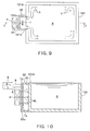
- Figs. 9 to 11 illustrate a sixth embodiment.
- a molten-metal driving room-forming part 5B is mounted on the outside of the furnace body 1 to form an accelerating space AS. This will be described in more detail below.
- a molten-metal driving room-forming part 5B illustrated in Fig. 11 is used in the sixth embodiment.
- the molten-metal driving room-forming part 5B has the shape of a container of which only a top plate portion among six surfaces is opened, and is mounted while electrodes 7a and 7b protrude from the inner surface of a bottom plate 5Ba.
- a side wall 101A of a furnace body 101 is provided with an outlet 101a from which molten metal M stored in the furnace body flows out and an inlet 101b through which molten metal M flows into the furnace body from the outside.
- the molten-metal driving room-forming part 5B illustrated in Fig. 11 is hermetically mounted on the side wall 101A of the furnace body 101 from the outside. Further, as in each of the above-mentioned embodiments, a magnetic field unit 4 is provided so as to face the electrodes 7a and 7b in the lateral direction in Fig. 10 with the bottom plate 5Ba of the molten-metal driving room-forming part 5B interposed therebetween. Due to the above-mentioned structure, current I flowing between the electrodes 7a and 7b and magnetic lines ML of force generated from the magnetic field unit 4 cross each other so as to be substantially vertical to each other, so that an electromagnetic force F illustrated in Fig. 9 is obtained.
- the molten metal M stored in the accelerating space AS is driven by the electromagnetic force F in the same manner as described above, so that the molten metal M stored in the furnace body 101 flows out from the outlet 101a and enters the accelerating space AS and the molten metal M stored in the accelerating space AS flows into the furnace body 101 from the inlet 101b. Accordingly, the molten metal M stored in the furnace body 1 is rotationally driven as illustrated by arrows A of Fig. 9 .
- Figs. 12 and 13 illustrate a seventh embodiment.
- the seventh embodiment shows an example where the magnetic field unit 4 is disposed between the electrodes 7a and 7b and the furnace body 101 so as to be isolated. This will be described in more detail below.
- a separate molten-metal driving/storing unit 105 is hermetically mounted on the furnace body 101.
- the molten-metal driving/storing unit 105 has an accelerating space AS so as to have a function of forming a receiving space 105A, in which the magnetic field unit 4 is received, together with the side wall 101A of the furnace body 101 in addition to a function as a so-called original molten-metal driving room-forming part. Since the receiving space 105A is naturally isolated from the molten metal M, the magnetic field unit 4 does not come into contact with the molten metal M.
- the electrodes 7a and 7b are provided in the accelerating space AS of the molten-metal driving/storing unit 105 in a vertical direction in Fig. 13 . Only the upper side of the accelerating space AS is opened as understood from Fig. 13 , and the accelerating space AS communicates with the furnace body 101 through the outlet 101a and the inlet 101b as understood from Fig. 12 . Further, the magnetic field unit 4 is received in the receiving space 105A. Accordingly, particularly, as understood from Fig. 13 , current I flowing between the electrodes 7a and 7b and the magnetic lines ML of force generated from the magnetic field unit 4 cross each other, so that an electromagnetic force F is generated. As in the above-mentioned embodiments, the molten metal M is eventually driven along the arrows A as illustrated in Fig. 12 .
- the following structure may be employed as an embodiment different from the above-mentioned embodiments. That is, for example, the molten-metal driving room-forming part 5 illustrated in Fig. 2 may be adapted so as to be capable of continuously rotating about an axis perpendicular to the plane of Fig. 2 . According to such a structure, it is possible to change the orientation of the molten-metal driving room-forming part 5 to the orientation of the molten-metal driving room-forming part 5 illustrated in Fig. 4(b) by the rotation. In this case, the orientation of the magnetic field unit 4 also needs to be changed so as to follow the change of the orientation of the molten-metal driving room-forming part 5.
- the N pole of the permanent magnet of the magnetic field unit 4 has faced the molten-metal driving room-forming part in each of the above-mentioned embodiments, but it is natural that an S pole may face the molten-metal driving room-forming part.
- One characteristic in the embodiments of the invention is to form a driving room, to make current I flow between a pair of electrodes provided in the driving room, and to apply a magnetic field to the current I so that the molten metal is efficiently agitated by an agitator.
- a material to be agitated molten metal or molten non-ferrous metal in the invention
- a force applied to the fluid is dispersed in all directions.
- the inventor found that the magnitude and direction of an agitating force are regulated and the molten metal can be driven with high efficiency when the agitating force is applied to the molten metal in a limited space (driving room DR).
- the invention is made on the basis of knowledge that is really unique to the inventor.
- the limited space (driving room DR) is formed by a cylindrical or U-shaped (channel type) molten-metal driving room-forming part 5.
- the material to be agitated is the molten metal and the molten non-ferrous metal in this case, but both molten metal and molten non-ferrous metal have high electrical conductivity (have low resistance). Accordingly, a voltage applied between the electrodes is small. For this reason, power consumption can be suppressed so as to be very small. Even though the invention is applied to a so-called large furnace, it is estimated that the value of power consumption is 10 Kw or less. Considering that an agitator in the related art (the most common linear furnace bottom agitator) requires power consumption of 500 Kw or more, it is found that the permanent magnet type molten-metal agitator of the invention is superior.
- the driving room DR (accelerating space AS) is formed, the current I flows in the driving room, the current I is made not to leak to the outside of the driving room DR, a magnetic field is applied to the current I so that an electromagnetic force F according to Fleming's rule is generated, and a driving force is applied to the molten metal M stored in the driving room DR serving as a closed space by the electromagnetic force F. Accordingly, it is possible to rotationally drive the molten metal M stored in the furnace body with high efficiency or to discharge the molten metal M stored in the furnace body to the outside with high efficiency by reliably driving the molten metal M that is stored in the driving room DR.
Landscapes
- Engineering & Computer Science (AREA)
- Mechanical Engineering (AREA)
- General Engineering & Computer Science (AREA)
- Power Engineering (AREA)
- Vertical, Hearth, Or Arc Furnaces (AREA)
- Waste-Gas Treatment And Other Accessory Devices For Furnaces (AREA)
Applications Claiming Priority (2)
| Application Number | Priority Date | Filing Date | Title |
|---|---|---|---|
| JP2012176275A JP5819270B2 (ja) | 2012-08-08 | 2012-08-08 | 永久磁石式筒型溶湯攪拌装置及び永久磁石式汲み出しポンプ付溶解炉 |
| PCT/JP2012/078636 WO2014024330A1 (ja) | 2012-08-08 | 2012-11-05 | 永久磁石式筒型溶湯攪拌装置及び永久磁石式汲み出しポンプ付溶解炉 |
Publications (3)
| Publication Number | Publication Date |
|---|---|
| EP2708839A1 EP2708839A1 (en) | 2014-03-19 |
| EP2708839A4 EP2708839A4 (en) | 2014-10-29 |
| EP2708839B1 true EP2708839B1 (en) | 2016-09-21 |
Family
ID=49584574
Family Applications (1)
| Application Number | Title | Priority Date | Filing Date |
|---|---|---|---|
| EP12868335.6A Active EP2708839B1 (en) | 2012-08-08 | 2012-11-05 | Permanent magnet type cylindrical molten metal stirring device, and melting furnace |
Country Status (7)
| Country | Link |
|---|---|
| US (1) | US9593884B2 (https=) |
| EP (1) | EP2708839B1 (https=) |
| JP (1) | JP5819270B2 (https=) |
| KR (1) | KR101644978B1 (https=) |
| CN (2) | CN203550641U (https=) |
| AU (1) | AU2012365869B2 (https=) |
| WO (1) | WO2014024330A1 (https=) |
Families Citing this family (14)
| Publication number | Priority date | Publication date | Assignee | Title |
|---|---|---|---|---|
| JP5819270B2 (ja) | 2012-08-08 | 2015-11-18 | 高橋 謙三 | 永久磁石式筒型溶湯攪拌装置及び永久磁石式汲み出しポンプ付溶解炉 |
| JP5551297B1 (ja) | 2013-08-08 | 2014-07-16 | 高橋 謙三 | 攪拌装置付き連続鋳造用鋳型装置 |
| JP5815763B2 (ja) * | 2014-01-24 | 2015-11-17 | 高橋 謙三 | 永久磁石式溶湯攪拌装置及びそれを有する溶解炉並びに連続鋳造装置 |
| JP6033807B2 (ja) * | 2014-03-27 | 2016-11-30 | 高橋 謙三 | 金属溶湯攪拌装置及び金属溶湯移送装置 |
| CA3092053C (en) | 2014-05-21 | 2026-01-06 | Novelis Inc. | Mixing eductor nozzle and flow control device |
| JP5948405B1 (ja) * | 2014-12-26 | 2016-07-06 | 高橋 謙三 | 導電性金属の駆動方法及び駆動装置 |
| JP6039010B1 (ja) * | 2015-04-23 | 2016-12-07 | 高橋 謙三 | 導電性金属溶解炉及びそれを備えた導電性金属溶解炉システム並びに導電性金属溶解方法 |
| EP3086069B1 (en) * | 2015-04-23 | 2019-06-05 | Digimet 2013 Sl | Furnace for melting and treating metal and metallic waste and method therefor |
| US10619928B2 (en) | 2015-06-03 | 2020-04-14 | Kenzo Takahashi | Conductive metal melting furnace, conductive metal melting furnace system equipped with same, and conductive metal melting method |
| JP6445201B2 (ja) * | 2017-04-13 | 2018-12-26 | 高橋 謙三 | 溶湯攪拌装置及びそれを備えた連続鋳造装置システム |
| CA3057130C (en) * | 2017-04-13 | 2021-12-28 | Kenzo Takahashi | Molten metal stirring device and continuous casting device system provided with same |
| AT521190B1 (de) * | 2018-04-27 | 2021-08-15 | Fill Gmbh | Verfahren zum Gießen einer Schmelze eines metallischen Werkstoffes, sowie zum Durchführen des Verfahrens ausgebildete Gießvorrichtung |
| JP7315218B2 (ja) * | 2019-12-24 | 2023-07-26 | 株式会社ヂーマグ | 金属溶湯駆動装置および金属溶湯駆動方法 |
| KR102478006B1 (ko) | 2020-12-03 | 2022-12-15 | 정승찬 | 자동차 긴급 제동장치 |
Family Cites Families (29)
| Publication number | Priority date | Publication date | Assignee | Title |
|---|---|---|---|---|
| JPS5857678B2 (ja) * | 1976-02-14 | 1983-12-21 | 株式会社東芝 | 電磁撹拌装置 |
| JP4245673B2 (ja) | 1996-11-14 | 2009-03-25 | 高橋 謙三 | 攪拌装置付きアルミ溶解炉、溶融アルミ攪拌装置及び溶湯アルミ攪拌方法 |
| KR100419757B1 (ko) * | 2001-08-22 | 2004-02-21 | 김춘식 | 연속주조장치에 있어서의 전자기 교반장치 |
| GB0213848D0 (en) * | 2002-06-15 | 2002-07-24 | Stein Atkinson Strody Ltd | Furnace |
| US20040234379A1 (en) | 2003-05-22 | 2004-11-25 | Nanocoolers, Inc. | Direct current magnetohydrodynamic pump configurations |
| KR101213559B1 (ko) | 2004-12-22 | 2012-12-18 | 겐조 다카하시 | 교반장치 및 방법과, 그 교반장치를 이용한 교반장치 부착용해로 |
| JP4413786B2 (ja) * | 2005-01-07 | 2010-02-10 | 高橋 謙三 | 溶湯攪拌装置及び攪拌装置付非鉄金属溶解炉 |
| JP4376771B2 (ja) | 2004-12-22 | 2009-12-02 | 高橋 謙三 | 攪拌装置 |
| JP2006349293A (ja) * | 2005-06-17 | 2006-12-28 | Kenzo Takahashi | 攪拌装置付溶解炉及び溶解炉用攪拌装置 |
| JP4772407B2 (ja) * | 2005-07-15 | 2011-09-14 | 高橋 謙三 | 溶湯搬送装置 |
| CN100373120C (zh) * | 2006-01-16 | 2008-03-05 | 山东华特磁电科技股份有限公司 | 超强永磁旋流搅拌器 |
| LV13636B (en) | 2006-04-19 | 2007-12-20 | Gors Sia | Technique and device for inductive mixing of liquid metal |
| US7651656B2 (en) * | 2006-07-20 | 2010-01-26 | Kenzo Takahashi | Melting furnace with agitator and agitator for melting furnace |
| EP2045553B1 (en) * | 2006-07-20 | 2012-04-25 | Kenzo Takahashi | Melting furnace with agitator |
| CN200963579Y (zh) * | 2006-11-02 | 2007-10-24 | 潍坊华特磁电设备有限公司 | 循环式永磁搅拌器 |
| CN100516253C (zh) * | 2007-07-10 | 2009-07-22 | 山东华特磁电科技股份有限公司 | 一种搅拌熔池及其在线设置方法 |
| CN201104121Y (zh) * | 2007-10-15 | 2008-08-20 | 曹建光 | 永磁搅拌合金电熔炉 |
| JP5242254B2 (ja) * | 2008-06-25 | 2013-07-24 | 高橋 謙三 | アルミニウム溶解炉及びアルミニウム溶解炉付溶解炉システム |
| JP5646138B2 (ja) * | 2008-06-27 | 2014-12-24 | 高橋 謙三 | 攪拌装置付溶解炉 |
| JP5163615B2 (ja) * | 2008-10-29 | 2013-03-13 | トヨタ自動車株式会社 | 撹拌装置、溶解装置および溶解方法 |
| JP4995234B2 (ja) * | 2008-12-26 | 2012-08-08 | 株式会社ヂーマグ | 非鉄金属溶湯ポンプ及びそれを用いた非鉄金属溶解炉 |
| WO2011038495A1 (en) | 2009-09-30 | 2011-04-07 | Novelis Inc. | Side well for metal melting furnace |
| JP5496647B2 (ja) * | 2009-12-28 | 2014-05-21 | 高橋 謙三 | 非鉄金属溶湯ポンプ |
| JP5546974B2 (ja) | 2010-04-07 | 2014-07-09 | 株式会社ヂーマグ | 非鉄金属溶湯ポンプ及びそれを用いた溶解炉システム |
| JP5432812B2 (ja) * | 2010-05-06 | 2014-03-05 | 三建産業株式会社 | 非鉄金属用溶解炉及び非鉄金属の溶解方法 |
| JP5669509B2 (ja) | 2010-07-16 | 2015-02-12 | 高橋 謙三 | 攪拌装置付き連続鋳造用鋳型装置 |
| CN201844702U (zh) * | 2010-11-02 | 2011-05-25 | 山东华特磁电科技股份有限公司 | 斜向流动搅拌熔炉 |
| JP5474879B2 (ja) * | 2011-07-04 | 2014-04-16 | 高橋 謙三 | 攪拌装置付金属溶解炉 |
| JP5819270B2 (ja) | 2012-08-08 | 2015-11-18 | 高橋 謙三 | 永久磁石式筒型溶湯攪拌装置及び永久磁石式汲み出しポンプ付溶解炉 |
-
2012
- 2012-08-08 JP JP2012176275A patent/JP5819270B2/ja active Active
- 2012-11-05 EP EP12868335.6A patent/EP2708839B1/en active Active
- 2012-11-05 US US14/111,130 patent/US9593884B2/en active Active
- 2012-11-05 KR KR1020137023852A patent/KR101644978B1/ko not_active Expired - Fee Related
- 2012-11-05 AU AU2012365869A patent/AU2012365869B2/en active Active
- 2012-11-05 WO PCT/JP2012/078636 patent/WO2014024330A1/ja not_active Ceased
-
2013
- 2013-07-29 CN CN201320456330.2U patent/CN203550641U/zh not_active Expired - Lifetime
- 2013-07-29 CN CN201310322723.9A patent/CN103575121B/zh not_active Expired - Fee Related
Also Published As
| Publication number | Publication date |
|---|---|
| JP5819270B2 (ja) | 2015-11-18 |
| US9593884B2 (en) | 2017-03-14 |
| US20140079561A1 (en) | 2014-03-20 |
| CN103575121A (zh) | 2014-02-12 |
| WO2014024330A1 (ja) | 2014-02-13 |
| CN203550641U (zh) | 2014-04-16 |
| EP2708839A1 (en) | 2014-03-19 |
| CN103575121B (zh) | 2015-12-23 |
| EP2708839A4 (en) | 2014-10-29 |
| KR101644978B1 (ko) | 2016-08-02 |
| AU2012365869B2 (en) | 2016-01-14 |
| JP2014035131A (ja) | 2014-02-24 |
| AU2012365869A1 (en) | 2014-02-27 |
| KR20140049978A (ko) | 2014-04-28 |
Similar Documents
| Publication | Publication Date | Title |
|---|---|---|
| EP2708839B1 (en) | Permanent magnet type cylindrical molten metal stirring device, and melting furnace | |
| JP2014035131A5 (https=) | ||
| EP2206998B1 (en) | Non-ferrous metal melt pump and non-ferrous metal melting furnace using the same | |
| US9597726B2 (en) | Metal melt circulating drive device and main bath including the same | |
| US3683094A (en) | Arc positioning system for rotating electrode wheel arc furnace | |
| CN103097554A (zh) | 用于在电弧炉中电磁搅拌的装置和方法 | |
| US10281216B2 (en) | Molten metal stirring device and molten metal transfer device | |
| EP2045553B1 (en) | Melting furnace with agitator | |
| CN105939799A (zh) | 永磁体式熔融金属搅拌装置、具有其的熔化炉和连续铸造装置 | |
| JP2006349293A (ja) | 攪拌装置付溶解炉及び溶解炉用攪拌装置 | |
| CA2831598C (en) | Permanent magnet type cylindrical molten-metal agitator and melting furnace with permanent magnet type suction pump | |
| JP5474879B2 (ja) | 攪拌装置付金属溶解炉 | |
| US12405062B2 (en) | Metal melt pump with heat insulating hood | |
| WO2023033637A1 (en) | A device for non-contact induction of flow in electrically conductive liquids | |
| CN104550798A (zh) | 一种铝合金半连续铸造电磁搅拌装置及方法 |
Legal Events
| Date | Code | Title | Description |
|---|---|---|---|
| PUAI | Public reference made under article 153(3) epc to a published international application that has entered the european phase |
Free format text: ORIGINAL CODE: 0009012 |
|
| 17P | Request for examination filed |
Effective date: 20130822 |
|
| AK | Designated contracting states |
Kind code of ref document: A1 Designated state(s): AL AT BE BG CH CY CZ DE DK EE ES FI FR GB GR HR HU IE IS IT LI LT LU LV MC MK MT NL NO PL PT RO RS SE SI SK SM TR |
|
| RIC1 | Information provided on ipc code assigned before grant |
Ipc: B22D 45/00 20060101ALI20140310BHEP Ipc: F27D 3/14 20060101ALI20140310BHEP Ipc: F27D 27/00 20100101AFI20140310BHEP |
|
| A4 | Supplementary search report drawn up and despatched |
Effective date: 20140926 |
|
| RIC1 | Information provided on ipc code assigned before grant |
Ipc: B22D 45/00 20060101ALI20140922BHEP Ipc: F27D 3/14 20060101ALI20140922BHEP Ipc: F27D 27/00 20100101AFI20140922BHEP Ipc: H02K 44/04 20060101ALI20140922BHEP |
|
| 17Q | First examination report despatched |
Effective date: 20150729 |
|
| DAX | Request for extension of the european patent (deleted) | ||
| GRAP | Despatch of communication of intention to grant a patent |
Free format text: ORIGINAL CODE: EPIDOSNIGR1 |
|
| INTG | Intention to grant announced |
Effective date: 20160411 |
|
| GRAS | Grant fee paid |
Free format text: ORIGINAL CODE: EPIDOSNIGR3 |
|
| GRAA | (expected) grant |
Free format text: ORIGINAL CODE: 0009210 |
|
| AK | Designated contracting states |
Kind code of ref document: B1 Designated state(s): AL AT BE BG CH CY CZ DE DK EE ES FI FR GB GR HR HU IE IS IT LI LT LU LV MC MK MT NL NO PL PT RO RS SE SI SK SM TR |
|
| REG | Reference to a national code |
Ref country code: GB Ref legal event code: FG4D |
|
| REG | Reference to a national code |
Ref country code: CH Ref legal event code: EP |
|
| REG | Reference to a national code |
Ref country code: AT Ref legal event code: REF Ref document number: 831391 Country of ref document: AT Kind code of ref document: T Effective date: 20161015 |
|
| REG | Reference to a national code |
Ref country code: IE Ref legal event code: FG4D |
|
| REG | Reference to a national code |
Ref country code: DE Ref legal event code: R096 Ref document number: 602012023406 Country of ref document: DE |
|
| REG | Reference to a national code |
Ref country code: CH Ref legal event code: NV Representative=s name: SCHNEIDER FELDMANN AG PATENT- UND MARKENANWAEL, CH |
|
| REG | Reference to a national code |
Ref country code: FR Ref legal event code: PLFP Year of fee payment: 5 |
|
| REG | Reference to a national code |
Ref country code: LT Ref legal event code: MG4D Ref country code: NL Ref legal event code: MP Effective date: 20160921 |
|
| PG25 | Lapsed in a contracting state [announced via postgrant information from national office to epo] |
Ref country code: LT Free format text: LAPSE BECAUSE OF FAILURE TO SUBMIT A TRANSLATION OF THE DESCRIPTION OR TO PAY THE FEE WITHIN THE PRESCRIBED TIME-LIMIT Effective date: 20160921 Ref country code: FI Free format text: LAPSE BECAUSE OF FAILURE TO SUBMIT A TRANSLATION OF THE DESCRIPTION OR TO PAY THE FEE WITHIN THE PRESCRIBED TIME-LIMIT Effective date: 20160921 Ref country code: RS Free format text: LAPSE BECAUSE OF FAILURE TO SUBMIT A TRANSLATION OF THE DESCRIPTION OR TO PAY THE FEE WITHIN THE PRESCRIBED TIME-LIMIT Effective date: 20160921 |
|
| REG | Reference to a national code |
Ref country code: NO Ref legal event code: T2 Effective date: 20160921 |
|
| PG25 | Lapsed in a contracting state [announced via postgrant information from national office to epo] |
Ref country code: GR Free format text: LAPSE BECAUSE OF FAILURE TO SUBMIT A TRANSLATION OF THE DESCRIPTION OR TO PAY THE FEE WITHIN THE PRESCRIBED TIME-LIMIT Effective date: 20161222 Ref country code: SE Free format text: LAPSE BECAUSE OF FAILURE TO SUBMIT A TRANSLATION OF THE DESCRIPTION OR TO PAY THE FEE WITHIN THE PRESCRIBED TIME-LIMIT Effective date: 20160921 Ref country code: LV Free format text: LAPSE BECAUSE OF FAILURE TO SUBMIT A TRANSLATION OF THE DESCRIPTION OR TO PAY THE FEE WITHIN THE PRESCRIBED TIME-LIMIT Effective date: 20160921 Ref country code: NL Free format text: LAPSE BECAUSE OF FAILURE TO SUBMIT A TRANSLATION OF THE DESCRIPTION OR TO PAY THE FEE WITHIN THE PRESCRIBED TIME-LIMIT Effective date: 20160921 |
|
| PG25 | Lapsed in a contracting state [announced via postgrant information from national office to epo] |
Ref country code: RO Free format text: LAPSE BECAUSE OF FAILURE TO SUBMIT A TRANSLATION OF THE DESCRIPTION OR TO PAY THE FEE WITHIN THE PRESCRIBED TIME-LIMIT Effective date: 20160921 Ref country code: EE Free format text: LAPSE BECAUSE OF FAILURE TO SUBMIT A TRANSLATION OF THE DESCRIPTION OR TO PAY THE FEE WITHIN THE PRESCRIBED TIME-LIMIT Effective date: 20160921 |
|
| PG25 | Lapsed in a contracting state [announced via postgrant information from national office to epo] |
Ref country code: PL Free format text: LAPSE BECAUSE OF FAILURE TO SUBMIT A TRANSLATION OF THE DESCRIPTION OR TO PAY THE FEE WITHIN THE PRESCRIBED TIME-LIMIT Effective date: 20160921 Ref country code: PT Free format text: LAPSE BECAUSE OF FAILURE TO SUBMIT A TRANSLATION OF THE DESCRIPTION OR TO PAY THE FEE WITHIN THE PRESCRIBED TIME-LIMIT Effective date: 20170123 Ref country code: ES Free format text: LAPSE BECAUSE OF FAILURE TO SUBMIT A TRANSLATION OF THE DESCRIPTION OR TO PAY THE FEE WITHIN THE PRESCRIBED TIME-LIMIT Effective date: 20160921 Ref country code: SK Free format text: LAPSE BECAUSE OF FAILURE TO SUBMIT A TRANSLATION OF THE DESCRIPTION OR TO PAY THE FEE WITHIN THE PRESCRIBED TIME-LIMIT Effective date: 20160921 Ref country code: CZ Free format text: LAPSE BECAUSE OF FAILURE TO SUBMIT A TRANSLATION OF THE DESCRIPTION OR TO PAY THE FEE WITHIN THE PRESCRIBED TIME-LIMIT Effective date: 20160921 Ref country code: IS Free format text: LAPSE BECAUSE OF FAILURE TO SUBMIT A TRANSLATION OF THE DESCRIPTION OR TO PAY THE FEE WITHIN THE PRESCRIBED TIME-LIMIT Effective date: 20170121 Ref country code: SM Free format text: LAPSE BECAUSE OF FAILURE TO SUBMIT A TRANSLATION OF THE DESCRIPTION OR TO PAY THE FEE WITHIN THE PRESCRIBED TIME-LIMIT Effective date: 20160921 Ref country code: BG Free format text: LAPSE BECAUSE OF FAILURE TO SUBMIT A TRANSLATION OF THE DESCRIPTION OR TO PAY THE FEE WITHIN THE PRESCRIBED TIME-LIMIT Effective date: 20161221 |
|
| REG | Reference to a national code |
Ref country code: DE Ref legal event code: R097 Ref document number: 602012023406 Country of ref document: DE |
|
| PLBE | No opposition filed within time limit |
Free format text: ORIGINAL CODE: 0009261 |
|
| STAA | Information on the status of an ep patent application or granted ep patent |
Free format text: STATUS: NO OPPOSITION FILED WITHIN TIME LIMIT |
|
| PG25 | Lapsed in a contracting state [announced via postgrant information from national office to epo] |
Ref country code: DK Free format text: LAPSE BECAUSE OF FAILURE TO SUBMIT A TRANSLATION OF THE DESCRIPTION OR TO PAY THE FEE WITHIN THE PRESCRIBED TIME-LIMIT Effective date: 20160921 |
|
| REG | Reference to a national code |
Ref country code: IE Ref legal event code: MM4A |
|
| 26N | No opposition filed |
Effective date: 20170622 |
|
| PG25 | Lapsed in a contracting state [announced via postgrant information from national office to epo] |
Ref country code: LU Free format text: LAPSE BECAUSE OF NON-PAYMENT OF DUE FEES Effective date: 20161130 |
|
| REG | Reference to a national code |
Ref country code: FR Ref legal event code: PLFP Year of fee payment: 6 |
|
| PG25 | Lapsed in a contracting state [announced via postgrant information from national office to epo] |
Ref country code: SI Free format text: LAPSE BECAUSE OF FAILURE TO SUBMIT A TRANSLATION OF THE DESCRIPTION OR TO PAY THE FEE WITHIN THE PRESCRIBED TIME-LIMIT Effective date: 20160921 Ref country code: IE Free format text: LAPSE BECAUSE OF NON-PAYMENT OF DUE FEES Effective date: 20161105 |
|
| PG25 | Lapsed in a contracting state [announced via postgrant information from national office to epo] |
Ref country code: CY Free format text: LAPSE BECAUSE OF FAILURE TO SUBMIT A TRANSLATION OF THE DESCRIPTION OR TO PAY THE FEE WITHIN THE PRESCRIBED TIME-LIMIT Effective date: 20160921 Ref country code: HU Free format text: LAPSE BECAUSE OF FAILURE TO SUBMIT A TRANSLATION OF THE DESCRIPTION OR TO PAY THE FEE WITHIN THE PRESCRIBED TIME-LIMIT; INVALID AB INITIO Effective date: 20121105 |
|
| PG25 | Lapsed in a contracting state [announced via postgrant information from national office to epo] |
Ref country code: MC Free format text: LAPSE BECAUSE OF FAILURE TO SUBMIT A TRANSLATION OF THE DESCRIPTION OR TO PAY THE FEE WITHIN THE PRESCRIBED TIME-LIMIT Effective date: 20160921 Ref country code: HR Free format text: LAPSE BECAUSE OF FAILURE TO SUBMIT A TRANSLATION OF THE DESCRIPTION OR TO PAY THE FEE WITHIN THE PRESCRIBED TIME-LIMIT Effective date: 20160921 Ref country code: MK Free format text: LAPSE BECAUSE OF FAILURE TO SUBMIT A TRANSLATION OF THE DESCRIPTION OR TO PAY THE FEE WITHIN THE PRESCRIBED TIME-LIMIT Effective date: 20160921 |
|
| PG25 | Lapsed in a contracting state [announced via postgrant information from national office to epo] |
Ref country code: MT Free format text: LAPSE BECAUSE OF NON-PAYMENT OF DUE FEES Effective date: 20161105 |
|
| PG25 | Lapsed in a contracting state [announced via postgrant information from national office to epo] |
Ref country code: AL Free format text: LAPSE BECAUSE OF FAILURE TO SUBMIT A TRANSLATION OF THE DESCRIPTION OR TO PAY THE FEE WITHIN THE PRESCRIBED TIME-LIMIT Effective date: 20160921 Ref country code: TR Free format text: LAPSE BECAUSE OF FAILURE TO SUBMIT A TRANSLATION OF THE DESCRIPTION OR TO PAY THE FEE WITHIN THE PRESCRIBED TIME-LIMIT Effective date: 20160921 |
|
| REG | Reference to a national code |
Ref country code: AT Ref legal event code: UEP Ref document number: 831391 Country of ref document: AT Kind code of ref document: T Effective date: 20160921 |
|
| REG | Reference to a national code |
Ref country code: CH Ref legal event code: PFA Owner name: TAKAHASHI, KENZO, JP Free format text: FORMER OWNER: TAKAHASHI, KENZO, JP |
|
| P01 | Opt-out of the competence of the unified patent court (upc) registered |
Effective date: 20230530 |
|
| PGFP | Annual fee paid to national office [announced via postgrant information from national office to epo] |
Ref country code: IT Payment date: 20241126 Year of fee payment: 13 |
|
| REG | Reference to a national code |
Ref country code: CH Ref legal event code: U11 Free format text: ST27 STATUS EVENT CODE: U-0-0-U10-U11 (AS PROVIDED BY THE NATIONAL OFFICE) Effective date: 20251201 |
|
| PGFP | Annual fee paid to national office [announced via postgrant information from national office to epo] |
Ref country code: DE Payment date: 20251119 Year of fee payment: 14 |
|
| PGFP | Annual fee paid to national office [announced via postgrant information from national office to epo] |
Ref country code: GB Payment date: 20251121 Year of fee payment: 14 |
|
| PGFP | Annual fee paid to national office [announced via postgrant information from national office to epo] |
Ref country code: NO Payment date: 20251125 Year of fee payment: 14 |
|
| PGFP | Annual fee paid to national office [announced via postgrant information from national office to epo] |
Ref country code: AT Payment date: 20251120 Year of fee payment: 14 |
|
| PGFP | Annual fee paid to national office [announced via postgrant information from national office to epo] |
Ref country code: FR Payment date: 20251125 Year of fee payment: 14 |
|
| PGFP | Annual fee paid to national office [announced via postgrant information from national office to epo] |
Ref country code: BE Payment date: 20251119 Year of fee payment: 14 |
|
| PGFP | Annual fee paid to national office [announced via postgrant information from national office to epo] |
Ref country code: CH Payment date: 20251201 Year of fee payment: 14 |