EP2708750A1 - Compresseur à spirales - Google Patents
Compresseur à spirales Download PDFInfo
- Publication number
- EP2708750A1 EP2708750A1 EP12786179.7A EP12786179A EP2708750A1 EP 2708750 A1 EP2708750 A1 EP 2708750A1 EP 12786179 A EP12786179 A EP 12786179A EP 2708750 A1 EP2708750 A1 EP 2708750A1
- Authority
- EP
- European Patent Office
- Prior art keywords
- scroll
- gas passageway
- gas
- type compressor
- main shaft
- Prior art date
- Legal status (The legal status is an assumption and is not a legal conclusion. Google has not performed a legal analysis and makes no representation as to the accuracy of the status listed.)
- Withdrawn
Links
Images


Classifications
-
- F—MECHANICAL ENGINEERING; LIGHTING; HEATING; WEAPONS; BLASTING
- F04—POSITIVE - DISPLACEMENT MACHINES FOR LIQUIDS; PUMPS FOR LIQUIDS OR ELASTIC FLUIDS
- F04C—ROTARY-PISTON, OR OSCILLATING-PISTON, POSITIVE-DISPLACEMENT MACHINES FOR LIQUIDS; ROTARY-PISTON, OR OSCILLATING-PISTON, POSITIVE-DISPLACEMENT PUMPS
- F04C29/00—Component parts, details or accessories of pumps or pumping installations, not provided for in groups F04C18/00 - F04C28/00
- F04C29/02—Lubrication; Lubricant separation
- F04C29/028—Means for improving or restricting lubricant flow
-
- F—MECHANICAL ENGINEERING; LIGHTING; HEATING; WEAPONS; BLASTING
- F01—MACHINES OR ENGINES IN GENERAL; ENGINE PLANTS IN GENERAL; STEAM ENGINES
- F01C—ROTARY-PISTON OR OSCILLATING-PISTON MACHINES OR ENGINES
- F01C21/00—Component parts, details or accessories not provided for in groups F01C1/00 - F01C20/00
- F01C21/10—Outer members for co-operation with rotary pistons; Casings
-
- F—MECHANICAL ENGINEERING; LIGHTING; HEATING; WEAPONS; BLASTING
- F04—POSITIVE - DISPLACEMENT MACHINES FOR LIQUIDS; PUMPS FOR LIQUIDS OR ELASTIC FLUIDS
- F04C—ROTARY-PISTON, OR OSCILLATING-PISTON, POSITIVE-DISPLACEMENT MACHINES FOR LIQUIDS; ROTARY-PISTON, OR OSCILLATING-PISTON, POSITIVE-DISPLACEMENT PUMPS
- F04C18/00—Rotary-piston pumps specially adapted for elastic fluids
- F04C18/02—Rotary-piston pumps specially adapted for elastic fluids of arcuate-engagement type, i.e. with circular translatory movement of co-operating members, each member having the same number of teeth or tooth-equivalents
- F04C18/0207—Rotary-piston pumps specially adapted for elastic fluids of arcuate-engagement type, i.e. with circular translatory movement of co-operating members, each member having the same number of teeth or tooth-equivalents both members having co-operating elements in spiral form
- F04C18/0215—Rotary-piston pumps specially adapted for elastic fluids of arcuate-engagement type, i.e. with circular translatory movement of co-operating members, each member having the same number of teeth or tooth-equivalents both members having co-operating elements in spiral form where only one member is moving
-
- F—MECHANICAL ENGINEERING; LIGHTING; HEATING; WEAPONS; BLASTING
- F04—POSITIVE - DISPLACEMENT MACHINES FOR LIQUIDS; PUMPS FOR LIQUIDS OR ELASTIC FLUIDS
- F04C—ROTARY-PISTON, OR OSCILLATING-PISTON, POSITIVE-DISPLACEMENT MACHINES FOR LIQUIDS; ROTARY-PISTON, OR OSCILLATING-PISTON, POSITIVE-DISPLACEMENT PUMPS
- F04C29/00—Component parts, details or accessories of pumps or pumping installations, not provided for in groups F04C18/00 - F04C28/00
- F04C29/04—Heating; Cooling; Heat insulation
-
- F—MECHANICAL ENGINEERING; LIGHTING; HEATING; WEAPONS; BLASTING
- F04—POSITIVE - DISPLACEMENT MACHINES FOR LIQUIDS; PUMPS FOR LIQUIDS OR ELASTIC FLUIDS
- F04C—ROTARY-PISTON, OR OSCILLATING-PISTON, POSITIVE-DISPLACEMENT MACHINES FOR LIQUIDS; ROTARY-PISTON, OR OSCILLATING-PISTON, POSITIVE-DISPLACEMENT PUMPS
- F04C29/00—Component parts, details or accessories of pumps or pumping installations, not provided for in groups F04C18/00 - F04C28/00
- F04C29/12—Arrangements for admission or discharge of the working fluid, e.g. constructional features of the inlet or outlet
-
- F—MECHANICAL ENGINEERING; LIGHTING; HEATING; WEAPONS; BLASTING
- F04—POSITIVE - DISPLACEMENT MACHINES FOR LIQUIDS; PUMPS FOR LIQUIDS OR ELASTIC FLUIDS
- F04C—ROTARY-PISTON, OR OSCILLATING-PISTON, POSITIVE-DISPLACEMENT MACHINES FOR LIQUIDS; ROTARY-PISTON, OR OSCILLATING-PISTON, POSITIVE-DISPLACEMENT PUMPS
- F04C2240/00—Components
- F04C2240/50—Bearings
- F04C2240/56—Bearing bushings or details thereof
-
- F—MECHANICAL ENGINEERING; LIGHTING; HEATING; WEAPONS; BLASTING
- F04—POSITIVE - DISPLACEMENT MACHINES FOR LIQUIDS; PUMPS FOR LIQUIDS OR ELASTIC FLUIDS
- F04C—ROTARY-PISTON, OR OSCILLATING-PISTON, POSITIVE-DISPLACEMENT MACHINES FOR LIQUIDS; ROTARY-PISTON, OR OSCILLATING-PISTON, POSITIVE-DISPLACEMENT PUMPS
- F04C2240/00—Components
- F04C2240/80—Other components
- F04C2240/807—Balance weight, counterweight
-
- F—MECHANICAL ENGINEERING; LIGHTING; HEATING; WEAPONS; BLASTING
- F04—POSITIVE - DISPLACEMENT MACHINES FOR LIQUIDS; PUMPS FOR LIQUIDS OR ELASTIC FLUIDS
- F04C—ROTARY-PISTON, OR OSCILLATING-PISTON, POSITIVE-DISPLACEMENT MACHINES FOR LIQUIDS; ROTARY-PISTON, OR OSCILLATING-PISTON, POSITIVE-DISPLACEMENT PUMPS
- F04C27/00—Sealing arrangements in rotary-piston pumps specially adapted for elastic fluids
- F04C27/005—Axial sealings for working fluid
Definitions
- the present invention relates to a scroll-type compressor having a front housing with multipath gas passageways through which the gas to be compressed is sucked.
- Patent document 1 discloses a scroll-type compressor provided with a main suction hole and auxiliary suction hole in a front housing.
- Patent document 2 discloses a scroll compressor of which passageway for a lubricant mist and a working medium flowing from a suction hole comprises two circuits (first circuit and second circuit).
- Patent document 3 discloses a scroll compressor provided with a plurality of suction passageways so that lubricating oil in the refrigerant passes by a sliding contact portion such as main shaft bearing through the suction passageways.
- a scroll-type compressor should be designed to prevent an excessive superheat degree of the suction gas in case that the pressure loss in the gas passageway from the suction port of the housing to the compression chamber sectioned with scroll walls to determine the suction displacement or the heat received from the sliding contact portion might increase the superheat degree of the suction gas.
- any conventional scroll-type compressors don't have a structure capable of satisfying both the prevention of excessive superheat of the suction gas and the lubrication of bearing, lip seal and thrust plate.
- a scroll-type compressor is a scroll-type compressor comprising: a housing which forms one portion of a compressor case and which supports a bearing for a main shaft having an opening through which a gas to be compressed is sucked, a suction space extending with a cylindrical-shape from the opening into the compressor, a first gas passageway extending from the suction space along a rotation axis of the main shaft, and a second gas passageway communicating with the first gas passageway and a space in which the bearing is disposed; and a shell which forms the other portion of the compressor case and which is fastened to the housing having a third gas passageway communicating with the first gas passageway and an internal space of a compression mechanism, characterized in that the first gas passageway and the third gas passageway communicate with each other at an outer side than a region where a bottom plate of a movable scroll can move with respect to a direction of a turning radius of the main shaft.
- Such a scroll-type compressor makes it possible that the above-described suction space and the first to third gas passageways control the superheat degree of the suction gas appropriately and lubricate the bearing for the main shaft and the sliding contact portion around the compression mechanism effectively.
- the bottom plate does not block the portion at which the passageways communicate with each other even when the main shaft rotates to swing the movable scroll, so that the suction gas flows in the gas passageways properly.
- the housing has a lubricating oil passageway which is independent from the first gas passageway and communicates with the suction space and the space in which the bearing is disposed.
- a lubricating oil passageway With such a lubricating oil passageway, the lubricating oil contained in the refrigeration gas or the like to be compressed which has been sucked from the opening on the housing could be delivered directly to the bearing for the main shaft from the suction space without going through the first gas passageway.
- a porous filling material is filled in a neighborhood of a portion which the suction space and the lubricating oil passageway communicate with each other.
- the porous filling material may be made of a porous material such as sponge and sintered metal, and alternatively made of a fiber material such as steel wool and porous filter.
- the housing and the shell are fastened with a plurality of fastening means while the first gas passageway and the third gas passageway communicate with each other in a region between the fastening means which are adjacent to each other.
- fastening means such as bolts fastening the housing and the shell
- the gas passageways could be configured to communicate with each other in the region between the adjacent bolts or the like, so that the compressor case is made compact.
- the suction space extends inward along the turning radius of the main shaft.
- the suction gas containing the lubricating oil could be easily led close to the sliding contact portion such as bearing required to be highly lubricated.
- Such a scroll-type compressor is suitable to a scroll-type compressor of which fixed scroll is formed integrally with the shell.
- a scroll-type compressor provided with a fixed scroll integral with the shell to which the present invention has been applied the superheat degree of the suction gas could be controlled appropriately without an additional peripheral port provided.
- a fin structure is formed inside the first gas passageway.
- the lubricating oil contained in the suction gas flowing in the first gas passageway could be trapped effectively.
- the lubricating oil trapped with the fin structure is delivered through the second gas passageway into the space in which the bearing is disposed so that the neighborhood of the bearing is improved in lubricity, and is delivered through the third gas passageway to the compression mechanism side so that the neighborhood of the compression mechanism is improved in lubricity.
- the first gas passageway is formed on a side surface of the suction space.
- the gas to be compressed flowing in the suction space could configure a flow bending at a right angle when flows into the first gas passageway.
- the lubricating oil in the gas to be compressed is subject to an inertial force at the bending portion of the gas flow, and therefore a part of the lubricating oil accumulates in the suction space without flowing into the first gas passageway.
- the lubricating oil in the gas to be compressed could be trapped selectively.
- the suction space extends to a level lower than the first gas passageway in a vertical direction.
- the lubricating oil trapped with the above-described simple separation mechanism could be stored at the bottom of the suction space, so that the trapped lubricating oil is efficiently supplied to each sliding contact portion if the suction space is provided with the lubricating oil passageway or the like at the bottom.
- the scroll-type compressor according to the present invention makes it possible that the suction gas flow is kept in a good flow condition while the superheat degree of the suction gas is controlled appropriately, so that the bearing for the main shaft and the sliding contact portions around the compression mechanism are lubricated effectively.
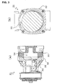
- Fig. 1 shows a scroll-type compressor according to the first embodiment of the present invention, where (a) is a front view and (b) is a longitudinal section view of section A-A in (a).
- main shaft 2 rotates to swing movable scroll 3, so that the gas is compressed by compression mechanism 5 comprising movable scroll 3 and fixed scroll 4.
- Refrigerant gas to be compressed is sucked from opening 7 on a side surface of front housing 6 into suction space 8.
- Suction space 8 is shaped like a cylinder extending toward the inside (or downward in Fig. 1 ) along the turning radius of main shaft 2 from opening 7.
- Suction space 8 communicates on the side surface with first gas passageway 9 extending along the rotation axis of main shaft 2. Diverging from first gas passageway 9, second gas passageway 13 extends toward bearing 11 for main shaft 2 opening on container space 12 where counterweight 10 is placed.
- Front housing 6 and shell 15 integral with fixed scroll 4 are fastened with bolts 14 as fastening means.
- first gas passageway 9 and third gas passageway 16 communicate with each other at an outer side (or an upper side in the Fig.) than a movable region where bottom plate 3a of movable scroll 3 can move, with respect to a direction of the turning radius of main shaft 2.
- Third gas passageway 16 extends at the inside of shell 15 along the rotation axis of main shaft 2 (or toward the right in the Fig.) so that first gas passageway 9 communicates with internal space 5a of compression mechanism 5. Because first gas passageway 9 and third gas passageway 16 communicate with each other at an outer side than the movable region of bottom plate 3a in the direction of the turning radius of main shaft 2, such a communication is maintained even when compressor 1 is in operation.
- suction space 8 On the bottom of suction space 8, lubricating oil passageway 17 extending to container space 12 without going through first gas passageway 9 as well as lubricating oil passageway 18 extending to lip seal lubrication space 20 without going through first gas passageway 9 are provided.
- suction space 8 functions as a simple oil separator for separating lubricating oil from suction gas to be compressed. Namely, the refrigerant component in the gas to be compressed tends to flow into first gas passageway 9 communicating with the side of suction space 8 while the lubricating oil component in the gas to be compressed tends to flow into lubricating oil passageway 17 communicating with the bottom of suction space 8. Therefore, the lubricating oil can be preferentially delivered toward bearing 11 for main shaft 2 required to be highly lubricated.
- Fig. 2 shows compressor 1 shown in Fig. 1 , where (a) is a longitudinal section view showing section B-B in Fig. 1(b) and (b) is a cross section view showing section C-C in Fig. 1 (b) .
- first gas passageway 9 extends with approximately uniform cross section toward shell 15 along the rotation axis of main shaft 2, so as to have almost the same cross-section shape as third gas passageway 16 near shell 15.
- FIG. 3 shows scroll-type compressor 31 according to the second embodiment of the present invention, where (a) is a longitudinal section view corresponding to Fig. 2(a) and (b) is a cross section view corresponding to Fig. 2(b) .
- Front housing 32 of compressor 31 is provided with first gas passageway 33 of which cross-section has been enlarged along the rotation axis of main shaft 2 to have a greater curvature and which extends toward shell 35 with almost the same cross-section shape as third gas passageway 34.
- FIG. 4 shows scroll-type compressor 41 according to the third embodiment of the present invention, where (a) is a longitudinal section view corresponding to Fig. 2(a) and (b) is a cross section view corresponding to Fig. 2(b) .
- Front housing 42 of compressor 41 is provided with first gas passageway 43 of which cross-section has been enlarged along the rotation axis of main shaft 2 by a constant ratio and which extends toward shell 45 with almost the same cross-section shape as third gas passageway 44.
- fins 46 having greater surface area extend along the rotation axis of main shaft 2.
- FIG. 5 shows scroll-type compressor 51 according to the fourth embodiment of the present invention, where (a) is a longitudinal section view corresponding to Fig. 2(a) and (b) is a cross section view corresponding to Fig. 2(b) .
- Front housing 52 of compressor 51 is provided with first gas passageway 53 of which cross-section has been enlarged along the rotation axis of main shaft 2 by a constant ratio and which extends toward shell 55 with almost the same cross-section shape as third gas passageway 54.
- a part of first gas passageway 53 is formed as fins 56 extending along the rotation axis of main shaft 2.
- Such a structure makes it possible that the lubricating oil in the gas flowing inside first gas passageway 53 is trapped by fins 56 and is led through second gas passageway 57 to bearings and the portion by which the movable scroll is supported as being brought into sliding contact.
- Fig. 6 is a longitudinal section view corresponding to Fig. 1(b) , showing scroll-type compressor 61 according to the fifth embodiment of the present invention.
- the bottom of suction space 63 of front housing 62 is filled with porous filling material 64 comprising porous particles or fibers.
- the filled porous filling material 64 can trap the lubricating oil component in the gas to be compressed efficiently, so that the lubricating oil is easily led to lubricating oil passageway 65, 66.
- the other configuration is the same as Fig. 1(b) with its detailed explanation omitted.
- the structure of the scroll-type compressor according to the present invention is applicable to every scroll-type compressor required to have a high lubricity on a sliding portion.
Landscapes
- Engineering & Computer Science (AREA)
- Mechanical Engineering (AREA)
- General Engineering & Computer Science (AREA)
- Rotary Pumps (AREA)
- Applications Or Details Of Rotary Compressors (AREA)
Applications Claiming Priority (2)
| Application Number | Priority Date | Filing Date | Title |
|---|---|---|---|
| JP2011108350A JP5782296B2 (ja) | 2011-05-13 | 2011-05-13 | スクロール型圧縮機 |
| PCT/JP2012/061634 WO2012157453A1 (fr) | 2011-05-13 | 2012-05-07 | Compresseur à spirales |
Publications (2)
| Publication Number | Publication Date |
|---|---|
| EP2708750A1 true EP2708750A1 (fr) | 2014-03-19 |
| EP2708750A4 EP2708750A4 (fr) | 2014-11-26 |
Family
ID=47176787
Family Applications (1)
| Application Number | Title | Priority Date | Filing Date |
|---|---|---|---|
| EP12786179.7A Withdrawn EP2708750A4 (fr) | 2011-05-13 | 2012-05-07 | Compresseur à spirales |
Country Status (5)
| Country | Link |
|---|---|
| US (1) | US20140119972A1 (fr) |
| EP (1) | EP2708750A4 (fr) |
| JP (1) | JP5782296B2 (fr) |
| CN (1) | CN103597211B (fr) |
| WO (1) | WO2012157453A1 (fr) |
Cited By (2)
| Publication number | Priority date | Publication date | Assignee | Title |
|---|---|---|---|---|
| EP3315781A1 (fr) * | 2016-10-31 | 2018-05-02 | Mitsubishi Heavy Industries Thermal Systems, Ltd. | Compresseur de type ouvert |
| EP3418569A4 (fr) * | 2016-07-11 | 2019-04-17 | Mitsubishi Heavy Industries Thermal Systems, Ltd. | Compresseur de fluide frigorigène de type ouvert |
Families Citing this family (4)
| Publication number | Priority date | Publication date | Assignee | Title |
|---|---|---|---|---|
| JP6291685B2 (ja) * | 2014-04-08 | 2018-03-14 | サンデンホールディングス株式会社 | スクロール型流体機械 |
| US11415135B2 (en) * | 2017-06-16 | 2022-08-16 | Trane International Inc. | Aerostatic thrust bearing and method of aerostatically supporting a thrust load in a scroll compressor |
| US20230037942A1 (en) * | 2017-06-16 | 2023-02-09 | Trane International Inc. | Aerostatic thrust bearing and method of aerostatically supporting a thrust load in a scroll compressor |
| US11761446B2 (en) * | 2021-09-30 | 2023-09-19 | Trane International Inc. | Scroll compressor with engineered shared communication port |
Citations (3)
| Publication number | Priority date | Publication date | Assignee | Title |
|---|---|---|---|---|
| EP0133625A1 (fr) * | 1983-08-16 | 1985-03-06 | Sanden Corporation | Système de lubrification pour un compresseur de type à volutes |
| EP0467342A1 (fr) * | 1990-07-18 | 1992-01-22 | Kabushiki Kaisha Toyoda Jidoshokki Seisakusho | Compresseur à spirales |
| US5395223A (en) * | 1992-02-21 | 1995-03-07 | Kabushiki Kaisha Toyoda Jidoshokki Seisakusho | Scroll type compressor having communication passage means with lubricating arrangement associated therewith |
Family Cites Families (15)
| Publication number | Priority date | Publication date | Assignee | Title |
|---|---|---|---|---|
| US2346398A (en) * | 1940-07-17 | 1944-04-11 | Gen Motors Corp | Oil burner |
| JPH0392580U (fr) * | 1990-01-11 | 1991-09-20 | ||
| JPH04279786A (ja) * | 1991-03-06 | 1992-10-05 | Toyota Autom Loom Works Ltd | スクロール型圧縮機 |
| JPH062673A (ja) * | 1992-06-18 | 1994-01-11 | Daikin Ind Ltd | 密閉横形スクロール流体機械 |
| JP2868998B2 (ja) * | 1994-03-14 | 1999-03-10 | 株式会社デンソー | スクロール型圧縮機 |
| JP3227075B2 (ja) * | 1994-12-08 | 2001-11-12 | 株式会社デンソー | スクロール型圧縮機 |
| JPH08200244A (ja) * | 1995-01-23 | 1996-08-06 | Nippon Soken Inc | スクロール型圧縮機 |
| JPH0932745A (ja) * | 1995-07-17 | 1997-02-04 | Matsushita Electric Ind Co Ltd | 開放型スクロール圧縮機 |
| CN1046790C (zh) | 1995-11-17 | 1999-11-24 | 倪诗茂 | 具有滑动平面推力轴承的容积式涡旋流体压缩装置 |
| JP2002257063A (ja) * | 2001-02-28 | 2002-09-11 | Sanden Corp | スクロール型圧縮機 |
| JP4403670B2 (ja) * | 2001-05-16 | 2010-01-27 | 株式会社デンソー | コンプレッサ |
| JP2004218536A (ja) * | 2003-01-15 | 2004-08-05 | Mitsubishi Heavy Ind Ltd | 電動圧縮機 |
| JP4822943B2 (ja) * | 2006-06-14 | 2011-11-24 | 三菱重工業株式会社 | 流体機械 |
| US8747088B2 (en) * | 2007-11-27 | 2014-06-10 | Emerson Climate Technologies, Inc. | Open drive scroll compressor with lubrication system |
| JP5421725B2 (ja) * | 2009-10-15 | 2014-02-19 | サンデン株式会社 | スクロール型流体装置 |
-
2011
- 2011-05-13 JP JP2011108350A patent/JP5782296B2/ja active Active
-
2012
- 2012-05-07 WO PCT/JP2012/061634 patent/WO2012157453A1/fr active Application Filing
- 2012-05-07 US US14/116,705 patent/US20140119972A1/en not_active Abandoned
- 2012-05-07 EP EP12786179.7A patent/EP2708750A4/fr not_active Withdrawn
- 2012-05-07 CN CN201280023365.5A patent/CN103597211B/zh active Active
Patent Citations (3)
| Publication number | Priority date | Publication date | Assignee | Title |
|---|---|---|---|---|
| EP0133625A1 (fr) * | 1983-08-16 | 1985-03-06 | Sanden Corporation | Système de lubrification pour un compresseur de type à volutes |
| EP0467342A1 (fr) * | 1990-07-18 | 1992-01-22 | Kabushiki Kaisha Toyoda Jidoshokki Seisakusho | Compresseur à spirales |
| US5395223A (en) * | 1992-02-21 | 1995-03-07 | Kabushiki Kaisha Toyoda Jidoshokki Seisakusho | Scroll type compressor having communication passage means with lubricating arrangement associated therewith |
Non-Patent Citations (1)
| Title |
|---|
| See also references of WO2012157453A1 * |
Cited By (2)
| Publication number | Priority date | Publication date | Assignee | Title |
|---|---|---|---|---|
| EP3418569A4 (fr) * | 2016-07-11 | 2019-04-17 | Mitsubishi Heavy Industries Thermal Systems, Ltd. | Compresseur de fluide frigorigène de type ouvert |
| EP3315781A1 (fr) * | 2016-10-31 | 2018-05-02 | Mitsubishi Heavy Industries Thermal Systems, Ltd. | Compresseur de type ouvert |
Also Published As
| Publication number | Publication date |
|---|---|
| US20140119972A1 (en) | 2014-05-01 |
| CN103597211A (zh) | 2014-02-19 |
| EP2708750A4 (fr) | 2014-11-26 |
| CN103597211B (zh) | 2016-08-17 |
| WO2012157453A1 (fr) | 2012-11-22 |
| JP2012237288A (ja) | 2012-12-06 |
| JP5782296B2 (ja) | 2015-09-24 |
Similar Documents
| Publication | Publication Date | Title |
|---|---|---|
| EP2708750A1 (fr) | Compresseur à spirales | |
| CN1325796C (zh) | 密闭型电动压缩机 | |
| KR100212292B1 (ko) | 압축기 | |
| US5088897A (en) | Swash plate type compressor with internal refrigerant and lubricant separating system | |
| JP4881666B2 (ja) | 横型スクロール圧縮機 | |
| CN101639069A (zh) | 叶片式压缩机 | |
| US9651047B2 (en) | Compressor having a partitioned discharge chamber | |
| JP2007182773A (ja) | 圧縮機 | |
| EP2236828A1 (fr) | Compresseur à spirale | |
| JP2013072365A (ja) | 圧縮機 | |
| CN103982437A (zh) | 容积型压缩机 | |
| JP4696240B2 (ja) | スクロール圧縮機 | |
| US10436201B2 (en) | Scroll compressor provided with a lubrication system | |
| CN114857010A (zh) | 一种压缩机的回油结构、压缩机和空调器 | |
| EP1954944B1 (fr) | Compresseur | |
| JP5209279B2 (ja) | スクロール圧縮機 | |
| CN101163886B (zh) | 旋转式压缩机 | |
| JP5372869B2 (ja) | 密閉型圧縮機及びこれを用いた冷蔵庫 | |
| JP2005146856A (ja) | レシプロ圧縮機 | |
| CN105508252B (zh) | 压缩机 | |
| JP6209730B2 (ja) | 密閉型圧縮機 | |
| JP2009510298A (ja) | 圧縮機 | |
| CN115324897A (zh) | 一种曲轴、涡旋压缩机及空调器 | |
| JP2007247562A (ja) | 冷媒圧縮機 | |
| KR100297177B1 (ko) | 유체기계 |
Legal Events
| Date | Code | Title | Description |
|---|---|---|---|
| PUAI | Public reference made under article 153(3) epc to a published international application that has entered the european phase |
Free format text: ORIGINAL CODE: 0009012 |
|
| 17P | Request for examination filed |
Effective date: 20131114 |
|
| AK | Designated contracting states |
Kind code of ref document: A1 Designated state(s): AL AT BE BG CH CY CZ DE DK EE ES FI FR GB GR HR HU IE IS IT LI LT LU LV MC MK MT NL NO PL PT RO RS SE SI SK SM TR |
|
| DAX | Request for extension of the european patent (deleted) | ||
| A4 | Supplementary search report drawn up and despatched |
Effective date: 20141029 |
|
| RIC1 | Information provided on ipc code assigned before grant |
Ipc: F04C 29/02 20060101ALI20141023BHEP Ipc: F04C 29/04 20060101ALI20141023BHEP Ipc: F04C 18/02 20060101AFI20141023BHEP |
|
| 17Q | First examination report despatched |
Effective date: 20150915 |
|
| RAP1 | Party data changed (applicant data changed or rights of an application transferred) |
Owner name: SANDEN HOLDINGS CORPORATION Owner name: HONDA MOTOR CO., LTD. |
|
| STAA | Information on the status of an ep patent application or granted ep patent |
Free format text: STATUS: THE APPLICATION IS DEEMED TO BE WITHDRAWN |
|
| 18D | Application deemed to be withdrawn |
Effective date: 20160830 |