EP2708687B1 - Bausatz für die Fertigung unterschiedlicher Varianten einer Betätigungshandhabe - Google Patents
Bausatz für die Fertigung unterschiedlicher Varianten einer Betätigungshandhabe Download PDFInfo
- Publication number
- EP2708687B1 EP2708687B1 EP13184400.3A EP13184400A EP2708687B1 EP 2708687 B1 EP2708687 B1 EP 2708687B1 EP 13184400 A EP13184400 A EP 13184400A EP 2708687 B1 EP2708687 B1 EP 2708687B1
- Authority
- EP
- European Patent Office
- Prior art keywords
- component
- hole pattern
- bearing device
- bearing
- construction set
- Prior art date
- Legal status (The legal status is an assumption and is not a legal conclusion. Google has not performed a legal analysis and makes no representation as to the accuracy of the status listed.)
- Active
Links
- 238000004519 manufacturing process Methods 0.000 title claims description 12
- 238000010276 construction Methods 0.000 claims description 36
- 238000009411 base construction Methods 0.000 claims description 14
- 239000000463 material Substances 0.000 claims description 2
- 230000015572 biosynthetic process Effects 0.000 claims 1
- 230000008878 coupling Effects 0.000 description 12
- 238000010168 coupling process Methods 0.000 description 12
- 238000005859 coupling reaction Methods 0.000 description 12
- 230000000284 resting effect Effects 0.000 description 3
- 230000000295 complement effect Effects 0.000 description 2
- 238000005553 drilling Methods 0.000 description 2
- 230000006978 adaptation Effects 0.000 description 1
- 230000005540 biological transmission Effects 0.000 description 1
- 239000002131 composite material Substances 0.000 description 1
- 238000011161 development Methods 0.000 description 1
- 230000018109 developmental process Effects 0.000 description 1
- 230000002349 favourable effect Effects 0.000 description 1
- 238000009434 installation Methods 0.000 description 1
Images


Classifications
-
- E—FIXED CONSTRUCTIONS
- E05—LOCKS; KEYS; WINDOW OR DOOR FITTINGS; SAFES
- E05B—LOCKS; ACCESSORIES THEREFOR; HANDCUFFS
- E05B65/00—Locks or fastenings for special use
- E05B65/10—Locks or fastenings for special use for panic or emergency doors
- E05B65/1046—Panic bars
- E05B65/106—Panic bars pivoting
- E05B65/1066—Panic bars pivoting the pivot axis being substantially parallel to the longitudinal axis of the bar
-
- E—FIXED CONSTRUCTIONS
- E05—LOCKS; KEYS; WINDOW OR DOOR FITTINGS; SAFES
- E05C—BOLTS OR FASTENING DEVICES FOR WINGS, SPECIALLY FOR DOORS OR WINDOWS
- E05C21/00—Arrangements or combinations of wing fastening, securing, or holding devices, not covered by a single preceding main group; Locking kits
-
- E—FIXED CONSTRUCTIONS
- E05—LOCKS; KEYS; WINDOW OR DOOR FITTINGS; SAFES
- E05B—LOCKS; ACCESSORIES THEREFOR; HANDCUFFS
- E05B63/00—Locks or fastenings with special structural characteristics
- E05B63/0056—Locks with adjustable or exchangeable lock parts
-
- E—FIXED CONSTRUCTIONS
- E05—LOCKS; KEYS; WINDOW OR DOOR FITTINGS; SAFES
- E05B—LOCKS; ACCESSORIES THEREFOR; HANDCUFFS
- E05B65/00—Locks or fastenings for special use
- E05B65/10—Locks or fastenings for special use for panic or emergency doors
- E05B65/1046—Panic bars
- E05B65/1053—Panic bars sliding towards and away form the door
-
- E—FIXED CONSTRUCTIONS
- E05—LOCKS; KEYS; WINDOW OR DOOR FITTINGS; SAFES
- E05B—LOCKS; ACCESSORIES THEREFOR; HANDCUFFS
- E05B9/00—Lock casings or latch-mechanism casings ; Fastening locks or fasteners or parts thereof to the wing
- E05B9/08—Fastening locks or fasteners or parts thereof, e.g. the casings of latch-bolt locks or cylinder locks to the wing
Definitions
- the invention relates to a kit for the production of different variants of an actuating handle for a lock for a door.
- the lock is intended for a door that. a fixed door frame and a door wing movably mounted therein.
- Preferred embodiments of such doors are single-leaf or double-leaf doors, each with a stop wing.
- the actuating handle has a horizontal in the mounting position on the door leaf actuating rod and at least one bearing device in which the actuating rod is movably mounted.
- the actuating handle is mounted on the door leaf, that is, the bearing device is mounted on the door leaf.
- the actuating handle is mounted so that the actuating rod is arranged horizontally on the door leaf.
- the actuating handle is designed as a handle bar, which is rotatably mounted about a horizontal axis of rotation of the bearing device.
- the handle bar is rotatably mounted in each case with its two ends in separate storage facilities, which are mounted on the door leaf.
- the handle bar is usually designed so that it has a horizontal straight actuating rod, at the ends of each of which a lever arm is connected.
- the free ends of the lever arms store rotatably in the two associated storage facilities.
- a bearing shaft is provided for the storage, which is rotatably mounted horizontally in the storage facilities and which is rotatably connected to the ends of the lever arms of the handle bar.
- the actuating rod forms a push rod, which is mounted displaceably in the bearing device perpendicular to the door leaf plane.
- the door lock is actuated upon actuation of the actuating rod, that is, the lock is actuated at least in the sense of unlocking.
- the door lock can be designed as a so-called mortise in the door, but alternatively it can also be designed as a door lock resting on the door.
- the DIN 11 25 describes such operating handles under the heading: panic door locks with horizontal operating rod for doors in escape routes.
- This DIN EN standard distinguishes between type A bar actuation (handle bar) and type B bar actuation (push bar).
- the handlebars are actuation handles that are rotatably mounted on the door leaf so as to be horizontally aligned about a horizontal bearing axis.
- the push rods are, as stated above, to operating rods, the are slidably mounted perpendicular to the door leaf level in the storage device on the door leaf.
- the handle bars and push rods actuating handles currently available on the market each have manufacturer-specific, different hole patterns which are each specifically designed for the associated doors of specific door manufacturers with regard to their hole pattern.
- the US 6,205,825 B1 describes the use of different bearing plates for a push rod. The bearing plates differ in the hole pattern for the mounting screws. The bearing plates are different hole pattern specific. Goal in the US 6,205,825 B1 is to replace different makes of push rods, each having different hole patterns, uniformly by a single push rod design.
- the invention has for its object to produce an alternative kit for the production of different variants of an actuating handle for a lock of a door, with which the use of different doors is possible.
- the invention solves this problem with a kit according to claim 1.
- It is a kit for the production of different variants of the actuating handle.
- the different variants to be made with the kit differ in their hole pattern for the mounting screws.
- the invention provides that the bearing device forms a component of the kit and this component bearing device is present in different versions, namely at least a first and a second embodiment.
- the different embodiments of the component bearing device have in their construction coincidentally an identical base construction unit, for example comprising a preferably housing-like bearing body, with bearing receptacle for a bearing shaft.
- the different versions of the component bearing device now differ but in their hole pattern for the mounting screws in such a way that the first embodiment of the component bearing means, that is, at least one embodiment of the component bearing means a first hole pattern for the fastening screws and the second embodiment of the component bearing means, that is, at least one other embodiment of this component has a second hole pattern for the fastening screws.
- the kit can thus be prepared by suitable selection of the relevant embodiment of the component bearing means or suitable combination of sub-components, which form the component bearing means, actuating handles which are mounted on the desired hole pattern of the door.
- the first hole pattern of the first embodiment of the component bearing device is formed by a hole pattern which is formed in a bearing plate which is part of the base construction unit and in that the second hole pattern of the second embodiment of the component bearing means formed by the hole pattern of an adapter bearing plate which is mounted on the bearing plate of the basic construction unit.
- the adapter bearing plate is disposed in or on the base construction unit, replacing the above-mentioned bearing plate of the basic construction unit.
- Adapter bearing plate means that the bearing plate of this second embodiment of the component bearing means has the second hole pattern for the mounting screws and thus modified or replaced the originally existing hole pattern, in the sense of an adaptation to a hole pattern of the door.
- the adapter bearing plate is used in particular when the component bearing device has its own bearing plate with certain other hole pattern.
- Embodiments of the kit are possible in which it is provided that the adapter bearing plate is formed as a component of the kit and / or as a subcomponent of the component bearing device. It may be provided here that the component adapter bearing plate is present in different versions, wherein the Different versions differ in the hole pattern for the mounting screws. This allows mounting on other doors with the relevant specific hole patterns of these designs.
- the base construction unit is designed as a separate structural unit.
- the adapter bearing plate is formed as a component of the kit and / or as a subcomponent of the component bearing device.
- the component adapter bearing plate is present in different versions, the different versions differ in the hole pattern for the mounting screws.
- the structural unit forming the basic construction unit has an integrated bearing plate with a hole pattern for the fastening screws. Integrated bearing plate means that in these cases the bearing plate forms part of the basic construction unit.
- the integrated bearing plate is designed differently.
- an identical bearing plate is used in the different embodiments and only another plate is placed as an adapter bearing plate on this bearing plate to produce the different versions of the component.
- the bearing plate is formed as a component of the kit and / or as a subcomponent of the component bearing device.
- the component basic construction unit can be combined with the component bearing plate and / or with the component adapter bearing plate.
- the basic construction unit has a bearing housing with a rotary bearing recess for receiving a bearing shaft, a return spring device and a driving device for actuating the lock.
- the kit may provide that the other components of the operating rod are formed by other components of the kit. It can be provided in this case a more or less strong division into components.
- the actuating rod of the actuating handle forms such a further component of the kit.
- the Actuating rod can be designed to be cut to length.
- the component actuating rod is present in different versions, wherein the different embodiments may differ in terms of their color and / or in terms of their length and / or in terms of their cross-section and / or in terms of their surface and / or in terms of their equipment Functional components and / or with regard to their material training.
- lever arm and / or the Hebelarmcru is formed for the rotatable mounting of the actuating rod as a component of the kit.
- component lever arm or Hebelarmcru is present in different versions.
- the different embodiments may differ in terms of their color and / or in terms of their length dimension and / or in terms of their structural design and / or in terms of their bearing support for the bearing shaft and / or in terms of their support receptacle for the actuating rod.
- the bearing shaft of the bearing device can be designed as a component of the bearing device, but also as a separate component of the kit. It can be provided that the component bearing device can be combined with a bearing shaft, which is designed as a separate structural unit and / or as a component of the kit.
- the component bearing shaft may be present in different versions in the kit, for example, with different terminal ends for engagement in the bearing receptacle of the lever arms of the actuating rod.
- the embodiments shown in the figures are each an actuating rod fitting for a door, preferably for a door in escape and rescue routes.
- the embodiments shown in the figures are very similar in construction.
- the same or functionally identical components are denoted by the same reference numerals in the figures.
- the actuating rod fitting is also referred to in the following description as Betuschistsstangenhandhabe or actuating rod means.
- the actuating rod handle of the embodiments of the figures is designed according to the nomenclature of DIN EN 1125 as a "handlebar". According to the standard, it is a type A bar operation.
- the type A operating rod - the so-called handle bar - has a horizontal pivot axis about which the actuating rod is pivotally when actuated by hand.
- the actuating rod 1 is mounted on the door leaf TF via a left-side bearing device 2 and a right-side bearing device 2.
- the actuating rod 1 has at its ends in each case a lever arm 1h, so that it has the shape of a U-shaped bracket.
- the free ends of the lever arms 1h are pivotally mounted in the bearing devices 2, 2 about a pivot axis XA.
- the fitting, ie the actuating rod device is mounted on the door so that the actuating rod 1 and, accordingly, the pivot axis XA are aligned parallel to the door leaf plane and that horizontally.
- the lock mechanism arranged in the door leaf, to which the actuating rod device is connected is actuated in the up direction.
- the lock mechanism is arranged in the door leaf immediately below one of the bearing devices 2 and connected via a connection device 3 arranged in the bearing device 2. The action of the actuating rod device including the connecting device 3 on the lock mechanism will be described in detail.
- the free end Each lever arm is rotatably connected to a driven-side bearing shaft 2a.
- the bearing shafts 2a are each aligned parallel to the actuating rod 1. They are from the respective free lever arm end on the side facing away from the actuating rod 1 side to the outside.
- the bearing shaft 2a is supported respectively in its associated bearing device 2, namely the left bearing shaft 2a in the left bearing device 2 and the right bearing shaft 2a in the right bearing device 2.
- connection of the actuating rod 1 to the bearing devices 2, 2 is a so-called Axial gleichan gleich in the illustrated embodiments. That is, for connecting the Hebelarmenden to the bearing shaft 2a of the associated bearing device 2 engages an axial connection piece of the bearing shaft 2a in a recess at the free end of the lever arm.
- Modified embodiments, in which the connection of the lever arms 1h respectively takes place radially on the bearing shaft 2a, are possible with otherwise the same configuration.
- the storage device 2 is formed in each case from a bearing body 2k.
- the bearing body 2k is U-shaped in cross section. It has a bearing plate 2p, projecting from the vertically upwards U-legs 2u.
- the U-legs 2u have cursing bearing receivers.
- the bearing mounts are penetrated by the respective associated bearing shaft 2a such that the bearing shaft are each mounted with their ends in the associated bearing mounts in the U-legs 2u rotatable about the axis XA.
- one end of the bearing shaft 2a is inserted directly in the bearing recess and rotatably supported, the other end of the bearing shaft carries a on the bearing shaft 2a rotatably mounted bushing 2b, which is rotatably inserted in the associated bearing mount.
- a leg spring 2s is mounted in each case, which, as FIG. 2b shows, with its one end to a stop pin in the U-leg 2u and supported with its other end a fixed to the bearing shaft 2a Hebelmit nutrition 2m.
- the hexagon engages twice in the bearing mount of the lever arm.
- a coupling pin 3k provided with a rotatably connected driver 3m.
- the coupling pin 3k engages in a locknut, not shown in the figures, which is part of the lock mechanism mounted in the door leaf.
- the lock nut represents a rotary receptacle of the lock mechanism. It is arranged so that the coupling pin 3k can be inserted in axial alignment.
- the coupling pin has a square. The lock nut drives the lock mechanism by the coupling pin 3k is rotated by actuation of the actuating rod 1.
- a gear is arranged, which causes a rotation of the coupling pin 3k upon rotation of the bearing shafts 2a.
- the transmission is formed by the fact that on the bearing shaft 2a rotatable lever cam 2m and the coupling pin 3k rotatably driver 3m cooperate, ie the lever cam 2m actuates the driver 3m, while the actuating rod 1 by operation by hand is pivoted down.
- the leg spring 2s is stretched. It serves after the actuation of the push rod to reset it again under the action of the spring 2s.
- the lock is preferably designed as a plug lock concealed in the door mounted.
- the lock bolt cooperates with a locking plate formed in the stationary door frame or in an adjacent inactive leaf.
- the lock can also be designed as a lock mounted on the door leaf.
- the controlled by the actuating rod latch can interact with a resting on the stationary door frame mounted strike plate.
- the lock may preferably be located in the actuating bar means, e.g. be integrated in a bearing housing.
- FIG. 5 shows a door leaf 17 on the inside of an actuating rod handle 1 and on the outside of a doorknob or door handle 10 is mounted.
- the operating rod handle 1 is a handlebar, ie type A actuating rod, namely an embodiment according to the embodiments of FIGS. 1 to 4 , It is a handle bar, in which the left and right lever arm of the actuating rod is connected axially to the horizontal bearing shaft of the associated bearing device, ie, an embodiment of the so-called axial concept.
- the pivot axis XA which is thus a so-called handlebar forming actuating rod 1, in the illustration in FIG. 5 located. It runs perpendicular to the plane of the drawing.
- the knob or door handle 10 mounted on the outside of the door panel TF is also merely schematic shown. It is essential that the axis X of the doorknob or pusher 10 is arranged at the same height above the floor, in which the pivot axis XA of the handle bar extends and also the axis XN of the nut of the built-in mortise mortise lock is arranged.
- the attachment of the handle bar 1 in the hole pattern of the rosette of the mounted on the outside of the door handle or door knob 10 takes place.
- the bearing device 2 of the actuating rod device via an adapter plate 5 is mounted on the door leaf.
- the adapter plate 5 is arranged between the bearing plate 3p of the bearing body 3k and the top of the door leaf TF, as shown in FIGS FIGS. 2b and 3b best seen.
- the adapter plate 5 is shown as a single part.
- the adapter plate 5 has a central passage opening for the coupling pin 3k.
- the passage opening is referred to above as the connection opening.
- this through-opening of the adapter plate 5 is arranged in alignment with the through-opening of the bearing plate 2p in such a way that the central center axes of the through-openings are aligned with each other.
- the adapter plate has 5 mounting holes 5f, which are provided for attachment to the door TF.
- the fastening holes 5f are designed as countersunk holes, so that the fastening screws can engage flatly with their screw head.
- the mounting holes 5f in the adapter plate 5 are in one formed first hole pattern, which is identical to the hole pattern of the mounting holes in the door leaf TF.
- the hole pattern of the mounting holes in the door leaf TF is standardized for standard doors.
- the adapter plate 5 is placed with the hole pattern of their mounting holes 5f on the relevant hole pattern of the door leaf.
- the bearing plate 2p however, has mounting holes 2f, which are arranged in a second hole pattern. These mounting holes are aligned in the mounting position with threaded pin 5g, which protrude from the adapter plate 5 upwards.
- the second hole pattern which thus form the fastening holes 2f in the bearing plate 2p, is the drilling pattern of so-called long rosettes in the illustrated exemplary embodiments.
- the first hole pattern which is formed in the door leaf TF, in the illustrated embodiments, the Bohrstory of so-called round rosettes.
- the mounting holes of this first hole pattern are arranged side by side in a horizontal line.
- the holes of the second hole pattern are arranged in a vertical line with each other.
- the hole spacing of the holes of the second hole pattern is greater than the hole spacing of the holes of the first hole pattern.
- the vertical connecting line of the holes of the second drilling pattern intersects the horizontal connecting line of the holes of the first hole pattern in the arrangement of a cross, the point of intersection being in the center of the superimposed adapter plate 5 and bearing plate 2p in the center the receiving bolt receiving the coupling pin 2k.
- the mounting holes 5f are arranged in opposite lateral edge regions of the adapter plate 5 and indeed in areas that are not covered by the resting in the mounting position bearing plate 2p of the bearing device 2.
- the mounting holes 5f and fastening screws inserted therein are thus accessible from outside in the mounting position.
- the FIGS. 2a and 3b show the mounting holes 5f without fixing screws used.
- the mounting holes 2f in the bearing plate 2p of the bearing device 2 are also accessible in the mounting position. They are arranged in the region of the two ends of the bearing plate 2p between the two U-legs 2u of the bearing body 2k.
- the FIGS. 2a and 3b show how in the mounting position the threaded pin 5g of the adapter plate 5 engage through the mounting holes 2f of the bearing plate and in each case via a nut screwed onto the free end of the threaded pin 5g screw connection is made.
- a cover 6 is placed on the bearing device 2.
- the cover 6 covers the entire storage device 2 and the underlying adapter plate 5 from.
- the cover 6 for this purpose has a special shape design in such a way that it hat-shaped or cap-shaped with an upper head portion which covers the bearing device 2 and a lower extension portion which covers the adapter plate 5, including the bearing plate 2 p projecting side regions the adapter plate 6.
- the operating rod handle on a special structural design which is characterized by a shell structure of the lever arms 1h.
- the lever arms 1h are composed in the illustrated embodiments of two shell parts 1 h1, 1 h2.
- a bearing recess ha is formed for the rotationally fixed receiving the bearing shaft 2a.
- the Lagerausströmung ha is formed as a closed recess which rotatably receives as a plug-in receptacle, the terminal end of the bearing shaft 2a. Closed recess means that the edge of the recess ha surrounds the circumference of the connection end of the bearing shaft 2a, that encloses.
- this bearing receptacle ha is as complementary in cross section with the cross section of the connecting end of the bearing shaft 2a, in the illustrated specific case in each case as a cross section with hexagonal contour.
- the other shell part has 1 h2 in the mounting position on the shell part 1h1 in the manner of a cover to form a lever arm 1h forming the composite body.
- the superimposed shell parts 1 h1, 1 h2 form a retaining recess hb for receiving the actuating rod 1.
- one half hb1, hb2 of the retaining recess hb is formed in the two shell parts 1h1, 1h2 in the respective end section.
- the Halterungsaus Principleung hb, as shown in the Figures 1b and 1c is recognizable, an elongated cross section.
- the actuating rod 1 has a complementary cross section, so that it is rotatably supported in its mounted position in the receptacle HB.
- the assembly is preferably carried out so that the actuating rod 1 is inserted with its end in the holder half of the shell part 1 h1 and Then the shell part 1 h2 is placed on the shell part 1h1 and the two shell parts 1 h1 and 1 h2 are clamped together via the screw connection.
- a screw is provided for each lever arm. To produce the screw, the screw is inserted with its screw shank into a through hole in the shell part 1h1 to stop and screwed the end of the screw in a formed in the shell part 1 h2 threaded hole.
- the shell part 1 h2 is formed in the case shown in the figures each in the manner of a cover.
- the shell part has transversely to its longitudinal extent a cross-section which is angular, consisting of two legs arranged at right angles to each other.
- the upper leg rests on the upper side of the shell part 1 h1.
- the lateral leg covers the side of the lever arm, namely the outside, which is remote from the actuating rod.
- This leg also covers the outer end side of the support receptacle, in which the end of the actuating rod 1 is inserted. This gives the lever arm on its outer side, which faces away from the actuating rod 1, a closed cover, which is formed by the shell part 1 h2.
- the shell part 1 h2 thus covering the outer side surface of the respective lever arm extends on the upper side of the lever arm from the lower end to over a part of the upper end of the shell part 1h1 having the bearing recess.
- the lever arm is covered in plan view from above largely or almost completely by the shell part 1 h2.
- the two lever arms each have a longitudinal joint on the inner sides facing each other, which is formed by the longitudinal edges of the shell parts 1h1 and 1h2 adjoining one another in this area.
- the illustrated in the figures embodiment of the operating rod handle with handle bar is, as explained, using the adapter plate 5 on the door TF mounted.
- the hole pattern of the adapter plate 5 makes it possible to mount the bearing device 2 of the operating rod handle in the hole pattern of the door leaf TF.
- the hole pattern of the door leaf is formed in the illustrated case as a hole pattern of a round rosette, i. two holes in a horizontal row of holes.
- the hole pattern of the adapter plate 5 corresponds to this hole pattern.
- the bearing plate 2p integrated in the bearing device 2 of the actuating rod handle has its own hole pattern, which in the case illustrated is the hole pattern of a vertical rosette, i. two holes in a vertical row of holes.
- the actuating rod handle with the bearing device 2 with integrated bearing plate 2p with hole pattern of the vertical rosette can be formed as a standard version of the actuating rod handle.
- the fitter then sets each on site for mounting the bearing device 2 on the door TF the adapter plate 5, which has a hole pattern of the door corresponding hole pattern. It is advantageous if a number of different adapter plates, each with a different hole pattern available. It must then be selected in each case the adapter plate, which has the matching to the hole pattern of the door leaf hole pattern.
- the selection of the adapter plate 5 and its attachment to the bearing device 2 already takes place in the context of manufacturing to different versions of the actuating rod handle with a Manufacture storage facility with specific hole pattern.
- a manufacturing kit may be provided, in which the bearing device 2 and the adapter plate 5 each represent separate components.
- the component bearing device can be designed as a standard component, which is present only in one embodiment, while the component adapter plate 5 can be contained in different versions in the manufacturing kit. The different versions of the adapter plate 5 then differ in each case in the hole pattern.
- the component bearing device 2 and the matching version of the adapter plate component is combined by the relevant adapter plate is mounted in or on the bearing device so that the hole pattern of the adapter plate is accessible to the storage facility in the context of manufacturing to be mounted on the door leaf using the fastening screws.
- actuating rods that is to say so-called grip rods, which are pivotable for actuation about a horizontal axis of rotation.
- actuating rods are designed as a type B actuating rods (see DIN EN 1125), that is called pressure rods which are movable for actuation perpendicular to the wing plane in the manner of a linear sliding movement.
- DIN EN 1125 a type B actuating rods
- the installation of these modified embodiments with type B actuating rod can be made with respect to the assembly in holes certain hole pattern, if necessary, with adapter plate, comparable as shown in the figures.
- the type B actuating rod handle bearing means may have a corresponding wellbore pattern as the type A actuating rod handle bearing means shown in the figures.
- You can have separate bearing plates with a hole pattern for the mounting screws.
- the bearing plates can also be integrated as a continuous bottom plate in the bearing device with a left and a right end portion of the bottom plate in which the mounting holes are formed in the respective hole pattern.
- one or more adapter plates in the end portion or a continuous common on this bearing plate Attached adapter plate or the bearing plate or bearing plates can be replaced by appropriate adapter plates or supplemented by applying the adapter plates to get over the adapter plates, the hole pattern or the hole patterns over which the bearing means on the wing by means of fastening screws can be fastened.
Description
- Die Erfindung betrifft einen Bausatz für die Fertigung unterschiedlicher Varianten einer Betätigungshandhabe für ein Schloss für eine Tür. Das Schloss ist für eine Tür bestimmt, die. einen ortsfesten Türrahmen und einen darin bewegbar gelagerten Türflügelaufweist. Bevorzugte Ausführungen solcher Türen sind einflügelige oder zweiflügelige Türen mit jeweils einem Anschlagdrehflügel.
- Die Betätigungshandhabe weist eine in der Montageposition am Türflügel horizontale Betätigungsstange und mindestens eine Lagereinrichtung auf, in der die Betätigungsstange bewegbar gelagert ist. Die Betätigungshandhabe ist an dem Türflügel gelagert, das heißt die Lagereinrichtung ist am Türflügel montiert. In der Regel ist die Betätigungshandhabe so montiert, dass die Betätigungsstange horizontal am Türflügel angeordnet ist. Es sind grundsätzlich zwei Ausführungen der Betätigungshandhabe möglich, nämlich eine Ausführung, bei der die Betätigungshandhabe als Griffstange ausgebildet ist, die um eine horizontale Drehachse der Lagereinrichtung drehbar gelagert ist.
- Hierbei ist die Griffstange jeweils mit ihren beiden Enden in separaten Lagereinrichtungen, die am Türflügel montiert sind, drehbar gelagert. Die Griffstange ist in der Regel so ausgebildet, dass sie eine horizontale gerade Betätigungsstange aufweist, an deren Enden jeweils ein Hebelarm angeschlossen ist. Die freien Enden der Hebelarme lagern in den beiden zugeordneten Lagereinrichtungen drehbar. In der Regel ist für die Lagerung eine Lagerwelle vorgesehen, die horizontal in den Lagereinrichtungen drehbar gelagert ist und, die drehfest mit den Enden der Hebelarme der Griffstange verbunden ist. In anderen ebenfalls möglichen Ausführungen einer Betätigungshandhabe bildet die Betätigungsstange eine Druckstange, die in der Lagereinrichtung senkrecht zur Türflügelebene verschiebbar gelagert ist. In allen Ausführungen der Betätigungshandhabe wird bei der Betätigung der Betätigungsstange das Türschloss betätigt, das heißt das Schloss wird zumindest im Sinne einer Entriegelung betätigt. Das Türschloss kann als sogenanntes Einsteckschloss im Türflügel gelagert ausgebildet sein, alternativ aber kann es auch als auf dem Türflügel aufliegendes Türschloss ausgebildet sein.
- Betätigungshandhaben als Griffstange oder als Druckstange ausgebildet, finden in der Praxis bereits Anwendung. Die DIN 11 25 beschreibt solche Betätigungshandhaben unter der Überschrift: Paniktürverschlüsse mit horizontaler Betätigungsstange für Türen in Rettungswegen. Diese DIN EN Norm unterscheidet zwischen Typ A Stangenbetätigung (Griffstange) und Typ B Stangenbetätigung (Druckstange). Bei den Griffstangen handelt es sich, wie oben erörtert, um Betätigungshandhaben, die am Türflügel horizontal ausgerichtet um eine horizontale Lagerachse drehbar gelagert sind. Bei den Druckstangen handelt es sich, wie oben dargelegt, um Betätigungsstangen, die senkrecht zur Türflügelebene verschiebbar in der Lagereinrichtung am Türflügel gelagert sind.
Die derzeit auf dem Markt befindlichen Griffstangen - und Druckstangen - Betätigungshandhaben weisen jeweils herstellerspezifisch unterschiedliche Lochbilder auf, die jeweils für die zugeordneten Türen bestimmter Türhersteller hinsichtlich ihres Lochbilds spezifisch ausgebildet sind.
DieUS 6,205,825 B1 beschreibt die Verwendung von verschiedenen Lagerplatten für eine Druckstange. Die Lagerplatten unterscheiden sich im Lochbild für die Befestigungsschrauben. Die Lagerplatten sind insoweit Lochbildspezifisch unterschiedlich. Ziel in derUS 6,205,825 B1 ist es, unterschiedliche Fabrikate von Druckstangen, die jeweils unterschiedliche Lochbilder aufweisen, einheitlich zu ersetzen durch eine einzige Druckstangenausführung. - Der Erfindung liegt die Aufgabe zugrunde, einen alternativen Bausatz für die Fertigung unterschiedlicher Varianten einer Betätigungshandhabe für ein Schloss einer Tür herzustellen, mit dem der Einsatz an unterschiedlichen Türen möglich ist.
Die Erfindung löst diese Aufgabe mit einem Bausatz gemäß Patentanspruch 1. Es handelt sich um einen Bausatz für die Fertigung unterschiedlicher Varianten der Betätigungshandhabe.
Die unterschiedlichen Varianten, die mit dem Bausatz zu fertigen sind, unterscheiden sich in ihrem Lochbild für die Befestigungsschrauben. Die Erfindung sieht dabei vor, dass die Lagereinrichtung eine Komponente des Bausatzes bildet und diese Komponente Lagereinrichtung in unterschiedlichen Ausführungen, nämlich mindestens einer ersten und einer zweiten Ausführung vorliegt. Die unterschiedlichen Ausführungen der Komponente Lagereinrichtung weisen in ihrem Aufbau übereinstimmend eine identische Basiskonstruktionseinheit auf, z.B. umfassend einen vorzugsweise gehäuseartigen Lagerkörper, mit Lageraufnahme für eine Lagerwelle. Die unterschiedlichen Ausführungen der Komponente Lagereinrichtung unterscheiden sich nun aber in ihrem Lochbild für die Befestigungsschrauben und zwar derart, dass die erste Ausführung der Komponente Lagereinrichtung, das heißt mindestens eine Ausführung der Komponente Lagereinrichtung ein erstes Lochbild für die Befestigungsschrauben und die zweite Ausführung der Komponente Lagereinrichtung, das heißt mindestens eine andere Ausführung dieser Komponente ein zweites Lochbild für die Befestigungsschrauben aufweist. Mit dem Bausatz können somit durch geeignete Auswahl der betreffenden Ausführung der Komponente Lagereinrichtung oder geeignete Kombination von Unterkomponenten, die die Komponente Lagereinrichtung bilden, Betätigungshandhaben hergestellt werden, die auf dem gewünschten Lochbild der Tür montierbar sind. Erfindungsgemäß ist vorgesehen, dass das erste Lochbild der ersten Ausführung der Komponente Lagereinrichtung durch ein Lochbild gebildet ist, das in einer Lagerplatte ausgebildet ist, die Bestandteil der Basiskonstruktionseinheit ist und, dass das zweite Lochbild der zweiten Ausführung der Komponente Lagereinrichtung durch das Lochbild einer Adapterlagerplatte gebildet ist, die auf der Lagerplatte der Basiskonstruktionseinheit angebracht ist. Es kann vorgesehen sein, dass die Adapterlagerplatte unter Ersatz der oben genannten Lagerplatte der Basiskonstruktionseinheit in oder an der Basiskonstruktionseinheit angeordnet ist.
Adapterlagerplatte bedeutet, dass die Lagerplatte dieser zweiten Ausführung der Komponente Lagereinrichtung das zweite Lochbild für die Befestigungsschrauben aufweist und damit das ursprünglich vorhandene Lochbild modifiziert oder ersetzt, im Sinne einer Adaption an ein Lochbild der Tür. Die Adapterlagerplatte kommt insbesondere dann zum Einsatz, wenn die Komponente Lagereinrichtung eine eigene Lagerplatte mit bestimmtem anderem Lochbild aufweist. Es sind Ausführungen des Bausatzes möglich, bei denen vorgesehen ist, dass die Adapterlagerplatte als Komponente des Bausatzes und/oder als Unterkomponente der Komponente Lagereinrichtung ausgebildet ist. Es kann hierbei vorgesehen sein, dass die Komponente Adapterlagerplatte in unterschiedlichen Ausführungen vorliegt, wobei die unterschiedlichen Ausführungen sich im Lochbild für die Befestigungsschrauben unterscheiden. Dies ermöglicht die Montage an weiteren Türen mit den betreffenden spezifischen Lochbildern dieser Ausführungen. - Die Tatsache, dass bei den unterschiedlichen Ausführungen der Komponente Lagereinrichtung jeweils eine identische Basiskonstruktionseinheit vorhanden ist, bedeutet, dass eine günstige Fertigung der unterschiedlichen Ausführungen dieser Komponente möglich ist. Es kann vorgesehen sein, dass die Basiskonstruktionseinheit als separate Baueinheit ausgebildet ist. Hierbei kann vorgesehen sein, dass die Adapterlagerplatte als Komponente des Bausatzes und/oder als Unterkomponente der Komponente Lagereinrichtung ausgebildet ist. Es kann vorgesehen sein, dass die Komponente Adapterlagerplatte in unterschiedlichen Ausführungen vorliegt, wobei die unterschiedlichen Ausführungen sich im Lochbild für die Befestigungsschrauben unterscheiden. Bei besonders bevorzugten Ausführungen kann vorgesehen sein, dass die die Basiskonstruktionseinheit bildende Baueinheit eine integrierte Lagerplatte mit einem Lochbild für die Befestigungsschrauben aufweist. Integrierte Lagerplatte bedeutet, dass in diesen Fällen die Lagerplatte einen Bestandteil der Basiskonstruktionseinheit bildet. Es ist möglich die unterschiedlichen Ausführungen der genannten Unterkomponente dadurch auszuführen, dass die integrierte Lagerplatte jeweils unterschiedlich gestaltet ist. Es ist jedoch alternativ auch möglich, dass jeweils eine identische Lagerplatte bei den unterschiedlichen Ausführungen verwendet wird und lediglich eine weitere Platte als Adapterlagerplatte auf diese Lagerplatte aufgesetzt wird, um die unterschiedlichen Ausführungen der Komponente herzustellen. Bei bevorzugten Ausführungen ist vorgesehen, dass die Lagerplatte als Komponente des Bausatzes und/oder als Unterkomponente der Komponente Lagereinrichtung ausgebildet ist.
In bevorzugten Weiterbildungen kann vorgesehen sein, dass die Komponente Basiskonstruktionseinheit mit der Komponente Lagerplatte und/oder mit der Komponente Adapterlagerplatte kombinierbar ist. - Was den Aufbau der Basiskonstruktionseinheit betrifft, kann vorgesehen sein, dass die Basiskonstruktionseinheit ein Lagergehäuse mit einer Drehlagerausnehmung zur Aufnahme einer Lagerwelle, einer Rückstellfedereinrichtung und einer Mitnehmereinrichtung zur Betätigung des Schlosses aufweist.
Der Bausatz kann vorsehen, dass die weiteren Bestandteile der Betätigungsstange durch weitere Komponenten des Bausatzes gebildet werden. Es kann hierbei eine mehr oder weniger starke Aufteilung in Komponenten vorgesehen sein. Vorzugsweise bildet die Betätigungsstange der Betätigungshandhabe eine solche weitere Komponente des Bausatzes. Die Betätigungsstange kann hierbei ablängbar ausgebildet sein. Es kann auch vorgesehen sein, dass die Komponente Betätigungsstange in unterschiedlichen Ausführungen vorliegt, wobei die unterschiedlichen Ausführungen sich unterscheiden können hinsichtlich ihrer Farbe und/oder hinsichtlich ihrer Länge und/oder hinsichtlich ihres Querschnitts und/oder hinsichtlich ihrer Oberfläche und/oder hinsichtlich ihrer Ausstattung mit Funktionskomponenten und/oder hinsichtlich ihrer Materialausbildung. - Es kann auch vorgesehen sein, dass der Hebelarm und/oder das Hebelarmpaar für die drehbare Lagerung der Betätigungsstange als Komponente des Bausatzes ausgebildet ist. Auch in diesem Falle kann vorgesehen sein, dass die Komponente Hebelarm oder Hebelarmpaar in unterschiedlichen Ausführungen vorliegt. Die unterschiedlichen Ausführungen können sich unterscheiden hinsichtlich ihrer Farbe und/oder hinsichtlich ihrer Längenabmessung und/oder hinsichtlich ihres konstruktiven Aufbaus und/oder hinsichtlich ihrer Lageraufnahme für die Lagerwelle und/oder hinsichtlich ihrer Halterungsaufnahme für die Betätigungsstange.
- Auch die Lagerwelle der Lagereinrichtung kann als Bauteil der Lagereinrichtung, aber auch als separate Komponente des Bausatzes ausgebildet sein. Es kann vorgesehen sein, dass die Komponente Lagereinrichtung mit einer Lagerwelle kombinierbar ist, die als separate Baueinheit und/oder als Komponente des Bausatzes ausgebildet ist.
- Auch die Komponente Lagerwelle kann in unterschiedlichen Ausführungen im Bausatz vorliegen, beispielsweise mit unterschiedlichen Anschlussenden zum Eingriff in die Lageraufnahme der Hebelarme der Betätigungsstange.
- Die Figuren zeigen:
- Figur 1a
- eine Draufsicht eines ersten Ausführungsbeispiels sowie Schnittansichten entlang Schnittlinie A-A einer Betätigungsstangeneinrichtung, wobei die Schlossmechanik im Flügel nicht dargestellt ist;
- Figur 1b:
- eine Ansicht der linken Seite der Betätigungsstangeneinrichtung in
Figur 1a , in Explosionsdarstellung sowie eine teilweise geschnittene Seitenansicht und eine teilweise geschnittene Draufsicht, ohne eingesetzte Betätigungsstange; - Figur 1c:
- eine Ansicht der rechten Seite der Betätigungsstangeneinrichtung in
Figur 1a , in Explosionsdarstellung sowie eine teilweise geschnittene Seitenansicht und eine teilweise geschnittene Draufsicht, ohne eingesetzte Betätigungsstange; - Figur 1d
- eine perspektivische Ansicht des Ausführungsbeispiels in
Fig. 1 a; - Figur 2a
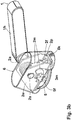
- ein perspektivische Darstellung eines zweiten Ausführungsbeispiels einer Betätigungsstangeneinrichtung, wobei die linke Seite der Betätigungsstangeneinrichtung mit der Lagereinrichtung mit Adapterplatte jedoch ohne Abdeckkappe dargestellt ist, ohne eingesetzte Betätigungsstange;
- Figur 2b
- eine perspektivische Darstellung des Ausführungsbeispiels in
Figur 2a ; jedoch in Draufsicht von oben her; - Figur 2c
- eine perspektivische Gesamtansicht des Ausführungsbeispiels in
Fig. 2a ; - Figur 3a
- eine
Figur 2a entsprechende perspektivische Darstellung des selben Ausführungsbeispiels, jedoch mit aufgesetzter Aufdeckkappe, ohne eingesetzte Betätigungsstange; - Figur 3b
- eine
Figur 3a entsprechende perspektivische Darstellung, jedoch mit der Abdeckkappe transparent dargestellt, ohne eingesetzte Betätigungsstange; - Figur 4
- eine perspektivische Draufsicht einer Adapterplatte wie sie in dem Ausführungsbeispiel der
Figuren 3a und3b eingesetzt ist, in Einzeldarstellung; - Figur 5
- eine Stirnansicht eines Türflügels, an dessen Innenseite eine Betätigungsstange und an dessen Außenseite ein Türknauf montiert ist.
- Bei den in den Figuren dargestellten Ausführungsbeispielen handelt es sich jeweils um einen Betätigungsstangenbeschlag für eine Tür, vorzugsweise für eine Tür in Flucht- und Rettungswegen. Die Ausführungsbeispiele, die in den Figuren dargestellt sind, sind im Aufbau sehr ähnlich. Die gleichen bzw. funktionsgleichen Bauteile sind in den Figuren mit den gleichen Bezugszeichen bezeichnet. Der Betätigungsstangenbeschlag ist in der folgenden Beschreibung auch als Betätigungsstangenhandhabe oder Betätigungsstangeneinrichtung bezeichnet.
- Die Betätigungsstangenhandhabe der Ausführungsbeispiele der Figuren ist gemäß der Nomenklatur der DIN EN 1125 als "Griffstange" ausgebildet. Gemäß der Norm handelt es sich um eine Typ A Stangenbetätigung. Die Typ A Betätigungsstange - die sogenannte Griffstange - weist eine horizontale Schwenkachse auf, um die die Betätigungsstange bei ihrer Betätigung von Hand schwenkbar ist.
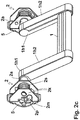
- Wie in
Figur 1a gezeigt, ist die Betätigungsstange 1 über eine linksseitige Lagereinrichtung 2 und eine rechtsseitige Lagereinrichtung 2 auf dem Türflügel TF gelagert. Die Betätigungsstange 1 weist an ihren Enden jeweils einen Hebelarm 1h auf, sodass sie die Formgestalt eines U-Bügels aufweist. Die freien Enden der Hebelarme 1h sind in den Lagereinrichtungen 2, 2 um eine Schwenkachse XA schwenkbar gelagert. Der Beschlag, d. h. die Betätigungsstangeneinrichtung ist auf dem Türflügel so montiert, dass die Betätigungsstange 1 und dementsprechend die Schwenkachse XA parallel zur Türflügelebene und zwar horizontal ausgerichtet sind. Durch Schwenken der Betätigungsstange 1 um diese horizontale Achse XA durch Herunterdrücken von Hand wird die im Türflügel angeordnete Schlossmechanik, an die die Betätigungsstangeneinrichtung angeschlossen ist, in Auf-Richtung betätigt. Die Schlossmechanik ist in dem Türflügel unmittelbar unterhalb von einer der Lagereinrichtungen 2 angeordnet und über eine in der Lagereinrichtung 2 angeordnete Anschlusseinrichtung 3 angeschlossen. Die Einwirkung der Betätigungsstangeneinrichtung einschließlich der Anschlusseinrichtung 3 auf die Schlossmechanik wird im Einzelnen noch beschrieben. - Die Betätigungsstange 1 weist bei den dargestellten Ausführungsbeispielen an ihren beiden Enden jeweils drehfest den Hebelarm 1h, 1h auf. Das freie Ende jedes Hebelarms ist drehfest mit einer abtriebsseitigen Lagerwelle 2a verbunden. Die Lagerwellen 2a sind jeweils parallel zur Betätigungsstange 1 ausgerichtet. Sie stehen von dem betreffenden freien Hebelarmende auf der von der Betätigungsstange 1 abgewandeten Seite nach außen ab. Die Lagerwelle 2a lagert jeweils in der ihr zugeordneten Lagereinrichtung 2 und zwar die linke Lagerwelle 2a in der linken Lagereinrichtung 2 und die rechte Lagerwelle 2a in der rechten Lagereinrichtung 2.
- Der Anschluss der Betätigungsstange 1 an den Lagereinrichtungen 2, 2 ist in den dargestellten Ausführungsbeispielen ein sogenannter Axialkonzeptanschluss. Das heißt, zum Anschluss der Hebelarmenden an der Lagerwelle 2a der zugeordneten Lagereinrichtung 2 greift ein axialer Anschlussstutzen der Lagerwelle 2a in eine Ausnehmung am freien Ende des Hebelarms ein. Abgewandelte Ausführungen, bei denen der Anschluss der Hebelarme 1h jeweils radial an der Lagerwelle 2a erfolgt, sind möglich mit im übrigen gleicher Ausgestaltung.
- Wie am besten in den
Figuren 1b und1c sowie in denFiguren 2a und2b zu erkennen ist, ist die Lagereinrichtung 2 jeweils aus einem Lagerkörper 2k gebildet. Der Lagerkörper 2k ist im Querschnitt U-förmig. Er weist eine Lagerplatte 2p auf, von der senkrecht nach oben U-Schenkel 2u abstehen. Die U-Schenkel 2u weisen miteinander verfluchtende Lageraufnahmen auf. Die Lageraufnahmen sind von der jeweils zugeordneten Lagerwelle 2a derartig durchgriffen, dass die Lagerwelle jeweils mit ihren Enden in den zugeordneten Lageraufnahmen in den U-Schenkeln 2u drehbar um die Achse XA gelagert sind. Wie dieFiguren 1b und1c erkennbar machen, ist das eine Ende der Lagerwelle 2a unmittelbar in der Lagerausnehmung eingesteckt und drehbar gelagert, das andere Ende der Lagerwelle trägt eine auf der Lagerwelle 2a drehbar gelagerte Lagerbuchse 2b, die drehfest in der zugeordneten Lageraufnahme eingesteckt ist. - Auf der Lagerwelle 2a ist jeweils eine Schenkelfeder 2s gelagert, die sich, wie
Figur 2b zeigt, mit ihrem einen Ende an einem Anschlagbolzen im U-Schenkel 2u abstützt und mit Ihren anderen Ende einen mit der Lagerwelle 2a festen Hebelmitnehmer 2m abstützt. Die drehfeste Verbindung der Lagerwelle 2a mit dem Hebelarm 1h der Befestigungsstange 1 erfolgt über einen Sechskant, wie aus denFiguren 1b und1c am besten zu erkennen ist. Der Sechskant greift in die Lageraufnahme des Hebelarms doppelt ein. - Zur Übertragung der Schwenkbewegung der Lagerwelle 2a auf die in den Figuren nicht dargestellte Schlossmechanik ist, wie in der
Figur 1b rechte Darstellung und in derFigur 1c mittlere Darstellung zu erkennen ist, einen Kupplungsbolzen 3k mit einem drehfest verbundenen Mitnehmer 3m vorgesehen. Der Kupplungsbolzen 3k greift in eine in den Figuren nicht dargestellte Schlossnuss, die Teil der im Türflügel montierten Schlossmechanik ist. Die Schlossnuss stellt eine Drehaufnahme der Schlossmechanik dar. Sie ist so angeordnet, dass der Kupplungsbolzen 3k axial fluchtend einsetzbar ist. Zur drehfesten Kupplung weist der Kupplungsbolzen einen Vierkant auf. Die Schlossnuss treibt die Schlossmechanik an, indem der Kupplungsbolzen 3k durch Betätigung der Betätigungsstange 1 gedreht wird. Zwischen der Lagerwellen 2a und dem Kupplungsbolzen 3k ist ein Getriebe angeordnet, das bei Drehung der Lagerwellen 2a eine Drehung des Kupplungsbolzens 3k bewirkt. Das Getriebe ist dadurch ausgebildet, dass der auf der Lagerwelle 2a drehfeste Hebelmitnehmer 2m und der auf dem Kupplungsbolzen 3k drehfeste Mitnehmer 3m zusammenwirken, d.h. der Hebelmitnehmer 2m betätigt den Mitnehmer 3m, während die Betätigungsstange 1 durch Betätigung von Hand nach unten geschwenkt wird. Dabei wird die Schenkelfeder 2s gespannt. Sie dient dazu nach der Betätigung der Druckstange, diese unter Wirkung der Feder 2s wieder zurückzustellen. - Bei dem dargestellten Ausführungsbeispiel ist das Schloss vorzugsweise als Steckschloss ausgebildet im Türflügel verdeckt montiert. Der Schlossriegel wirkt mit einem im ortsfesten Türrahmen oder in einem angrenzenden Standflügel ausgebildetem Schließblech zusammen. Bei abgewandelten Ausführungsbeispielen kann das Schloss auch als auf dem Türflügel aufliegend montiertes Schloss ausgebildet sein. Der durch die Betätigungsstange gesteuerte Riegel kann mit einem auf dem ortsfesten Türrahmen aufliegend montiertem Schließblech zusammenwirken. Das Schloss kann vorzugsweise in der Betätigungsstangeneinrichtung, z.B. in einem Lagergehäuse integriert sein.
-
Figur 5 zeigt einen Türflügel 17 an dessen Innenseite eine Betätigungsstangenhandhabe 1 und an dessen Außenseite ein Türknauf oder Türdrücker 10 montiert ist. Bei der Betätigungsstangenhandhabe 1 handelt es sich um eine Griffstange, d.h. Typ A Betätigungsstange, und zwar um eine Ausführung entsprechend den Ausführungsbeispielen derFiguren 1 bis 4 . Es handelt sich um eine Griffstange, bei der der linke und rechte Hebelarm der Betätigungsstange jeweils an der horizontalen Lagerwelle der zugeordneten Lagereinrichtung axial angeschlossen ist, d.h. eine Ausführung des sogenannten Axialkonzeptes. - Die Schwenkachse XA, der also eine sogenannte Griffstange bildende Betätigungsstange 1 ist, in der Darstellung in
Figur 5 eingezeichnet. Sie verläuft senkrecht zur Zeichnungsebene. Der Knauf oder Türdrücker 10, der an der Außenseite des Türflügels TF montiert ist, ist ebenfalls lediglich schematisch dargestellt. Wesentlich ist, dass die Achse X des Türknaufs oder Drückers 10 in derselben Höhe über dem Boden angeordnet ist, in der die Schwenkachse XA der Griffstange verläuft und auch die Achse XN der Nuss des im Türflügel TF eingebauten Einsteckschlosses angeordnet ist. Vorteilhafterweise ist bei diesem Ausführungsbeispiel vorgesehen, dass die Befestigung der Griffstange 1 im Lochbild der Rosette des an der Außenseite des Türflügels montierten Türdrückers oder Türknaufs 10 erfolgt. - Bei den in den Figuren dargestellten Ausführungsbeispielen ist die Lagereinrichtung 2 der Betätigungsstangeneinrichtung über eine Adapterplatte 5 auf dem Türflügel montiert. Die Adapterplatte 5 ist zwischen der Lagerplatte 3p des Lagerkörpers 3k und der Oberseite des Türflügels TF angeordnet, wie dies aus den
Figuren 2b und3b am besten zu erkennen ist. In derFigur 4 ist die Adapterplatte 5 als Einzelteil dargestellt. - Die Adapterplatte 5 weist eine zentrale Durchgriffsöffnung für den Kupplungszapfen 3k auf. Die Durchgriffsöffnung ist vorangehend als Anschlussöffnung bezeichnet. In der Montageposition ist diese Durchgriffsöffnung der Adapterplatte 5 fluchtend mit der Durchgriffsöffnung der Lagerplatte 2p angeordnet und zwar derart, dass die zentralen Mittelachsen der Durchgriffsöffnungen miteinander fluchten.
- Wesentlich ist, dass die Adapterplatte 5 Befestigungslöcher 5f aufweist, die zur Befestigung am Türflügel TF vorgesehen sind. Die Befestigungslöcher 5f sind als Senklöcher ausgebildet, sodass die Befestigungsschrauben mit ihrem Schraubenkopf plan eingreifen können. In der Darstellung in
Figur 2a undFigur 3a sind in den Befestigungslöchern 5f keine Befestigungsschrauben eingesetzt dargestellt. Die Befestigungslöcher 5f in der Adapterplatte 5 sind in einem ersten Bohrbild ausgebildet, das identisch ist mit dem Bohrbild der Befestigungslöcher im Türflügel TF. Das Bohrbild der Befestigungslöcher im Türflügel TF ist bei Normtüren genormt. Die Adapterplatte 5 ist mit dem Bohrbild ihrer Befestigungslöcher 5f auf das betreffende Bohrbild des Türflügels abgestellt.
Die Lagerplatte 2p weist hingegen Befestigungslöcher 2f auf, die in einem zweiten Bohrbild angeordnet sind. Diese Befestigungslöcher fluchten in der Montageposition mit Gewindezapfen 5g, die von der Adapterplatte 5 nach oben abstehen. - Das zweite Bohrbild, das also die Befestigungslöcher 2f in der Lagerplatte 2p bilden ist bei den dargestellten Ausführungsbeispielen das Bohrbild von sogenannten Langrosetten. Das erste Bohrbild, das im Türflügel TF ausgebildet ist, ist bei den dargestellten Ausführungsbeispielen das Bohrbild von sogenannten Rundrosetten. Die Befestigungslöcher dieses ersten Bohrbilds sind in einer horizontalen Linie nebeneinander angeordnet. Im Unterschied hierzu sind die Löcher des zweiten Bohrbilds in einer vertikalen Linie untereinander angeordnet. Der Lochabstand der Löcher des zweiten Bohrbilds ist größer als der Lochabstand der Löcher des ersten Bohrbilds. Wie in den Figuren für die dargestellten Ausführungsbeispiele dargestellt, schneidet die vertikale Verbindungslinie der Löcher des zweiten Bohrbilds die horizontale Verbindungslinie der Löcher des ersten Bohrbilds in der Anordnung eines Kreuzes, wobei der Kreuzungspunkt im Zentrum der aufeinanderliegenden Adapterplatte 5 und Lagerplatte 2p liegt und zwar im Zentrum der den Kupplungsbolzen 2k aufnehmenden Aufnahmeöffnungen.
- Wie in den
Figuren 2a ,2b ,3b und4 zu erkennen ist, sind in dem dargestellten Fall die Befestigungslöcher 5f in gegenüberliegenden seitlichen Randbereichen der Adapterplatte 5 angeordnet und zwar in Bereichen, die von der in der Montageposition aufliegenden Lagerplatte 2p der Lagereinrichtung 2 nicht überdeckt sind. Die Befestigungslöcher 5f und darin eingesetzte Befestigungsschrauben sind somit in der Montageposition von außen zugänglich. DieFiguren 2a und3b zeigen die Befestigungslöcher 5f ohne eingesetzte Befestigungsschrauben. - Die Befestigungslöcher 2f in der Lagerplatte 2p der Lagereinrichtung 2 sind ebenfalls in der Montageposition zugängig. Sie sind im Bereich der beiden Enden der Lagerplatte 2p zwischen den beiden U-Schenkeln 2u des Lagerkörpers 2k angeordnet. Die
Figuren 2a und3b zeigen, wie in der Montageposition die Gewindezapfen 5g der Adapterplatte 5 durch die Befestigungslöcher 2f der Lagerplatte hindurch greifen und jeweils über eine auf das freie Ende der Gewindezapfen 5g aufgeschraubten Mutter die Schraubverbindung hergestellt ist. - In den
Figuren 3a und3b ist eine Abdeckhaube 6 auf die Lagereinrichtung 2 aufgesetzt. Die Abdeckhaube 6 deckt dabei die gesamte Lagereinrichtung 2 und die darunterliegende Adapterplatte 5 ab. Die Abdeckhaube 6 hat hierfür eine spezielle Formgestaltung und zwar derart, dass sie hut- oder kappenförmig ausgebildet ist mit einem oberen Kopfabschnitt, der die Lagereinrichtung 2 überdeckt und einem unteren Erweiterungsabschnitt, der die Adapterplatte 5 abdeckt, und zwar einschließlich der die Lagerplatte 2p überstehenden Seitenbereiche der Adapterplatte 6. - Bei den in den Figuren dargestellten Ausführungsbeispielen weist die Betätigungsstangenhandhabe einen besonderen konstruktiven Aufbau auf, der durch einen Schalenaufbau der Hebelarme 1h gekennzeichnet ist. Die Hebelarme 1h sind bei den dargestellten Ausführungsbeispielen aus zwei Schalenteilen 1 h1, 1 h2 zusammengesetzt. In dem Schalenteil 1h1 ist eine Lagerausnehmung ha ausgebildet zur drehfesten Aufnahme der Lagerwelle 2a. Die Lagerausnehmung ha ist als geschlossene Ausnehmung ausgebildet, die als Steckaufnahme das Anschlussende der Lagerwelle 2a drehfest aufnimmt. Geschlossene Ausnehmung bedeutet, dass der Rand der Ausnehmung ha den Umfang des Anschlussendes der Lagerwelle 2a umgibt, dass heißt umschließt. Im dargestellten Fall ist diese Lageraufnahme ha als im Querschnitt komplementär mit dem Querschnitt des Anschlussendes der Lagerwelle 2a, im dargestellten konkreten Fall jeweils als Querschnitt mit Sechskantkontur.
- Das andere Schalenteil hat 1 h2 liegt in der Montageposition auf dem Schalenteil 1h1 in Art einer Abdeckung auf unter Ausbildung eines den Hebelarm 1h bildenden zusammengesetzten Körpers.
- An dem von der Lageraufnahme ha abgewandten Ende bilden die aufeinanderliegenden Schalenteile 1 h1, 1 h2 eine Halterungsausnehmung hb zur Aufnahme der Betätigungsstange 1. Hierfür ist in den beiden Schalenteilen 1h1, 1h2 in dem betreffenden Endabschnitt eine Hälfte hb1, hb2 der Halterungsausnehmung hb ausgebildet. Die Halterungsausnehmung hb weist, wie aus den
Figuren 1b und1c erkennbar ist, einen länglichen Querschnitt auf. Die Betätigungsstange 1 weist einen hierzu komplementären Querschnitt auf, sodass sie in ihrer montierten Stellung in der Aufnahme hb drehfest gehaltert ist. Die Montage erfolgt vorzugsweise so, dass die Betätigungsstange 1 mit ihrem Ende in die Halterungshälfte des Schalenteils 1 h1 eingelegt wird und sodann das Schalenteil 1 h2 auf das Schalenteil 1h1 aufgesetzt wird und über die Schraubverbindung die beiden Schalenteile 1 h1 und 1 h2 zusammengespannt werden. In den Explosionsdarstellungen derFiguren 1 b und 1c ist für jeden Hebelarm hierfür eine Schraube vorgesehen. Zur Herstellung der Schraubverbindung wird die Schraube mit ihrem Schraubenschaft in ein Durchgangsloch im Schalenteil 1h1 auf Anschlag eingesteckt und das Schraubenende in einem im Schalenteil 1 h2 ausgebildeten Gewindeloch eingeschraubt. - Das Schalenteil 1 h2 ist in dem in den Figuren dargestellten Fall jeweils in Art einer Abdeckung ausgebildet. Das Schalenteil weist quer zu seiner Längserstreckung einen Querschnitt auf, der winkelig ist, bestehend aus zwei rechtwinkelig zueinander angeordneten Schenkeln. In der Montageposition liegt der obere Schenkel auf der Oberseite des Schalenteils 1 h1 auf. Der seitliche Schenkel deckt die Seite des Hebelarms ab, und zwar die Außenseite, die von der Betätigungsstange abgewandt ist. Dieser Schenkel überdeckt dabei auch die äußere Stirnseite der Halterungsaufnahme, in der das Ende der Betätigungsstange 1 eingesteckt ist. Damit erhält der Hebelarm auf seiner Außenseite, die von der Betätigungsstange 1 abgewandt ist, eine geschlossene Abdeckung, die gebildet ist durch das Schalenteil 1 h2. Das Schalenteil 1 h2, das so die äußere Seitenfläche des jeweiligen Hebelarms abdeckt, erstreckt sich auf der Oberseite des Hebelarms von dem unteren Ende bis über ein Teil des oberen Endes des Schalenteils 1h1, welches die Lagerausnehmung aufweist. Somit wird der Hebelarm bei Draufsicht von oben weitgehend oder nahezu vollständig durch das Schalenteil 1 h2 abgedeckt.
- Die beiden Hebelarme weisen auf den einander zugewandten Innenseiten jeweils eine Längsfuge auf, die durch die in diesem Bereich einander angrenzenden Längsränder der Schalenteile 1h1 und 1 h2 gebildet wird.
- Das in den Figuren dargestellte Ausführungsbeispiel der Betätigungsstangenhandhabe mit Griffstange ist, wie erläutert, unter Verwendung der Adapterplatte 5 am Türflügel TF montierbar. Das Lochbild der Adapterplatte 5 erlaubt es, die Lagereinrichtung 2 der Betätigungsstangenhandhabe in dem Lochbild des Türflügels TF zu montieren. Das Lochbild des Türflügels ist in dem dargestellten Fall als Lochbild einer Rundrosette ausgebildet, d.h. zwei Löcher in einer horizontalen Lochreihe. Das Lochbild der Adapterplatte 5 entspricht diesem Lochbild. Die in der Lagereinrichtung 2 der Betätigungsstangenhandhabe integrierte Lagerplatte 2p weist ein eigenes Lochbild auf, das in dem dargestellten Fall das Lochbild einer Vertikalrosette ist, d.h. zwei Löcher in einer vertikalen Lochreihe. Die Betätigungsstangenhandhabe mit der Lagereinrichtung 2 mit integrierter Lagerplatte 2p mit Lochbild der Vertikalrosette kann als Standardausführung der Betätigungsstangenhandhabe ausgebildet sein. Der Monteur setzt dann jeweils vor Ort zur Montage der Lagereinrichtung 2 am Türflügel TF die Adapterplatte 5 ein, die ein dem Lochbild des Türflügels entsprechendes Lochbild aufweist. Vorteilhaft ist es, wenn eine Reihe unterschiedlicher Adapterplatten mit jeweils unterschiedlichem Lochbild zur Verfügung steht. Es muss dann jeweils die Adapterplatte, die das zu dem Lochbild des Türflügels passende Lochbild aufweist, ausgewählt werden.
- Alternativ ist es auch möglich, dass die Auswahl der Adapterplatte 5 und ihr Anbringen an der Lagereinrichtung 2 bereits im Rahmen der Fertigung erfolgt, um unterschiedliche Ausführungen der Betätigungsstangenhandhabe mit einer Lagereinrichtung mit jeweils spezifischem Lochbild zu fertigen. Hierfür kann ein Fertigungsbausatz vorgesehen sein, bei dem die Lagereinrichtung 2 und die Adapterplatte 5 jeweils separate Komponenten darstellen. Die Komponente Lagereinrichtung kann als einheitliche Standardkomponente ausgebildet sein, die nur in einer Ausführung vorliegt, während die Komponente Adapterplatte 5in unterschiedlichen Ausführungen in dem Fertigungsbausatz enthalten sein kann. Die unterschiedlichen Ausführungen der Adapterplatte 5 unterscheiden sich dann jeweils im Lochbild. Für die Fertigung der Betätigungsstangenhandhabe mit bestimmtem Lochbild wird die Komponente Lagereinrichtung 2 und die passende Ausführung der Komponente Adapterplatte kombiniert, indem im Rahmen der Fertigung die betreffende Adapterplatte in oder an der Lagereinrichtung so angebracht wird, dass das Lochbild der Adapterplatte zugänglich ist, um die Lagereinrichtung über die Befestigungsschrauben am Türflügel zu montieren.
- Die in den Figuren dargestellten Ausführungsbeispiele sind wie erläutert Typ A Betätigungsstangen, dass heißt sogenannte Griffstangen, die zur Betätigung um eine horizontale Drehachse schwenkbar sind. Es sind jedoch auch abgewandelte Ausführungsbeispiele möglich, bei denen die Betätigungsstangen als Typ B Betätigungsstangen (siehe DIN EN 1125) ausgeführt sind, dass heißt sogenannte Druckstangen, die zur Betätigung senkrecht zur Flügelebene in Art einer linearen Schiebebewegung bewegbar sind. Die Montage dieser abgewandelten Ausführungsbeispiele mit Typ B Betätigungsstange kann hinsichtlich der Montage in Löchern bestimmten Lochbilds gegebenenfalls auch mit Adapterplatte, vergleichbar wie in den Figuren dargestellt, erfolgen. Die Lagereinrichtungen der Typ B Betätigungsstangenhandhabe können ein entsprechendes Bohrlochbild wie die Lagereinrichtungen der Typ A Betätigungsstangenhandhabe, die in den Figuren dargestellt sind, aufweisen. Sie können separate Lagerplatten mit einem Lochbild für die Befestigungsschrauben aufweisen. Die Lagerplatten können aber auch als durchgehende Bodenplatte in der Lagereinrichtung integriert sein mit einem linken und einem rechten Endabschnitt der Bodenplatte, in dem die Befestigungslöcher in dem betreffenden Lochbild ausgebildet sind. In entsprechender Weise können auf dieser Lagerplatte eine oder mehrere Adapterplatten in dem Endabschnitt oder eine durchgehende gemeinsame Adapterplatte angebracht sein oder die Lagerplatte bzw. Lagerplatten können durch entsprechende Adapterplatten ersetzt oder durch Aufbringen der Adapterplatten ergänzt werden, um über die Adapterplatten das Lochbild bzw. die Lochbilder zu erhalten, über die die Lagereinrichtung auf dem Flügel mittels der Befestigungsschrauben befestigbar ist.
-
- TF
- Türflügel
- XA
- Schwenkachse
- XN
- Achse der Schlossnuss 4n
- X
- Achse des Türdrückers 10
- 1
- Betätigungsstange, Griffstange
- 1h
- Hebelarm
- 1h1
- Schalenteil
- 1h2
- Schalenteil
- ha
- Lageraufnahme
- hb
- Halterungsaufnahme
- 2b
- Lagerbuchse
- 2a
- Lagerwelle
- 2m
- Hebelmitnehmer
- 2s
- Schenkelfeder
- 2
- Lagereinrichtung
- 2k
- Lagerkörper
- 2u
- U-Schenkel
- 2p
- Lagerplatte
- 2f
- Befestigungslöcher (zweites Bohrbild)
- 3
- Anschlusseinrichtung
- 3k
- Kupplungsbolzen
- 3m
- Mitnehmer
- 4n
- Schlossnuss
- 5
- Adapterlagerplatte
- 5f
- Befestigungslöcher (erstes Bohrbild)
- 5g
- Gewinde
- 6
- Abdeckkappe
- 6k
- Klemmschraube
Claims (15)
- Bausatz für die Fertigung unterschiedlicher Varianten einer Betätigungshandhabe für ein Schloss einer Tür mit einem ortsfesten Rahmen und einem darin bewegbar gelagerten Türflügel,
wobei die Betätigungshandhabe eine in Montageposition am Türflügels horizontale Betätigungsstange (1) mit mindestens einer Lagereinrichtung (2) aufweist, in der die Betätigungsstange (1) bewegbar gelagert ist, vorzugsweise als Griffstange (1) ausgebildet um eine horizontale Drehachse (XA) der Lagereinrichtung (2) drehbar oder als Druckstange ausgebildet in der Lagereinrichtung senkrecht zur Türflügelebene verschiebbar,
wobei die unterschiedlichen Varianten der Betätigungshandhabe, die mit dem Bausatz zu fertigen sind, sich in ihrem Lochbild für die Befestigungsschrauben unterscheiden,
wobei vorgesehen ist,
dass die Lagereinrichtung (2) eine Komponente des Bausatzes bildet und diese Komponente Lagereinrichtung (2) in unterschiedlichen Ausführungen vorliegt, und zwar in mindestens einer ersten und einer zweiten Ausführung,
wobei die unterschiedlichen Ausführungen der Komponente Lagereinrichtung (2) in ihrem Aufbau übereinstimmend eine identische Basiskonstruktionseinheit aufweisen, sich aber in ihrem Lochbild für die Befestigungsschrauben unterscheiden, so dass die erste Ausführung der Komponente Lagereinrichtung (2) ein erstes Lochbild für die Befestigungsschrauben und die zweite Ausführung der Komponente Lagereinrichtung (2) ein zweites Lochbild für die Befestigungsschrauben aufweist,
dadurch gekennzeichnet,
dass das erste Lochbild der ersten Ausführung der Komponente Lagereinrichtung (2) durch ein Lochbild gebildet ist, das in einer Lagerplatte (2p) ausgebildet ist, die Bestandteil der Basiskonstruktionseinheit ist, und,
dass das zweite Lochbild der zweiten Ausführung der Komponente Lagereinrichtung (2) durch das Lochbild einer Adapterlagerplatte (5) gebildet ist, die auf der Lagerplatte (2p) der Basiskonstruktionseinheit angebracht ist. - Bausatz nach Anspruch 1,
dadurch gekennzeichnet,
dass die Adapteriagerplatte (5) unter Ersatz der oben genannten Lagerplatte (2p) der Basiskonstruktionseinheit in oder an der Basiskonstruktionseinheit angeordnet ist. - Bausatz nach einem der vorangehenden Ansprüche,
dadurch gekennzeichnet,
dass die Adapterlagerplatte (5) als Komponente des Bausatzes und/oder als Unterkomponente der Komponente Lagereinrichtung (2) ausgebildet ist. - Bausatz nach Anspruch 3,
dadurch gekennzeichnet,
dass die Komponente Adapterlagerplatte in unterschiedlichen Ausführungen vorliegt, wobei die unterschiedlichen Ausführungen sich im Lochbild für die Befestigungsschrauben unterscheiden. - Bausatz nach einem der vorangehenden Ansprüche,
dadurch gekennzeichnet,
dass die Basiskonstruktionseinheit als separate Baueinheit ausgebildet ist. - Bausatz nach Anspruch 5,
dadurch gekennzeichnet,
dass die als separate Baueinheit ausgebildete Basiskonstruktionseinheit als Komponente des Bausatzes und/oder als Unterkomponente der Komponente Lagereinrichtung (2) ausgebildet ist. - Bausatz nach Anspruch 6,
dadurch gekennzeichnet,
dass die Komponente Basiskonstruktionseinheit in unterschiedlichen Ausführungen vorliegt, wobei die unterschiedlichen Ausführungen sich darin unterscheiden, dass sie eine Lagerplatte (2p) mit einem Lochbild für die Befestigungsschrauben oder keine Lagerplatte (2p) mit einem Lochbild für die Befestigungsschrauben aufweisen oder, dass sie eine Lagerplatte (2p) mit unterschiedlichem Lochbild für die Befestigungsschrauben aufweisen. - Bausatz nach einem der vorangehenden Ansprüche,
dadurch gekennzeichnet,
dass die Lagerplatte (2p) als Komponente des Bausatzes und/oder als Unterkomponente der Komponente Lagereinrichtung (2) ausgebildet ist. - Bausatz nach einem der Ansprüche 6 bis 8,
dadurch gekennzeichnet,
dass die Komponente Basiskonstruktionseinheit mit der Komponente Lagerplatte (2p) und/oder mit der Komponente Adapterlagerplatte (5) kombinierbar ist. - Bausatz nach Anspruch 9,
dadurch gekennzeichnet,
dass die Komponente Basiskonstruktionseinheit keine eigene Lagerplatte (2p) mit einem Lochbild für die Befestigungsschrauben aufweist. - Bausatz nach einem der vorangehenden Ansprüche,
dadurch gekennzeichnet,
dass die Betätigungsstange (1) der Betätigungshandhabe als Komponente des Bausatzes ausgebildet ist. - Bausatz nach Anspruch 11,
dadurch gekennzeichnet,
dass die Komponente Betätigungsstange (1) in unterschiedlichen Ausführungen vorliegt,
wobei die unterschiedlichen Ausführungen sich hinsichtlich ihrer Farbe und/oder ihrer Länge und/oder ihres Querschnitts und/oder ihrer Oberfläche und/oder ihrer Ausstattung mit Funktionskomponenten und/oder ihrer Materialausbildung unterscheiden. - Bausatz nach einem der vorangehenden Ansprüche,
dadurch gekennzeichnet,
dass ein Hebelarm (1h) oder ein Hebelarmpaar (1h, 1h) für die drehbare Lagerung der Betätigungsstange (1) in der Lagereinrichtung (2) als Komponente des Bausatzes ausgebildet ist. - Bausatz nach Anspruch 13,
dadurch gekennzeichnet,
dass die Komponente Hebelarm (1h) oder Hebelarmpaar (1h, 1h) in unterschiedlichen Ausführungen vorliegen,
wobei die unterschiedlichen Ausführungen sich hinsichtlich ihrer Farbe und/oder ihrer Längenabmessung und/oder ihres konstruktiven Aufbaus und/oder ihrer Lageraufnahme für die Lagerwelle der Lagereinrichtung und/oder ihrer Halterungsaufnahme für die Betätigungsstange unterscheiden. - Bausatz nach einem der vorangehenden Ansprüche,
dadurch gekennzeichnet,
dass die Komponente Lagereinrichtung (2) mit einer Lagerwelle (2a) kombinierbar ist, die als separate Baueinheit und/oder als Komponente des Bausatzes ausgebildet ist.
Priority Applications (1)
| Application Number | Priority Date | Filing Date | Title |
|---|---|---|---|
| PL13184400T PL2708687T3 (pl) | 2012-09-13 | 2013-09-13 | Zestaw konstrukcyjny do wytwarzania różnych wariantów klamki drzwi |
Applications Claiming Priority (5)
| Application Number | Priority Date | Filing Date | Title |
|---|---|---|---|
| DE102012018418 | 2012-09-13 | ||
| DE201210025514 DE102012025514A1 (de) | 2012-09-13 | 2012-12-21 | Beschlag mit Betätigungshandhabe für eine Tür, Fenster oder dergleich mit Adapterlagerplatte |
| DE102012025513.6A DE102012025513A1 (de) | 2012-09-13 | 2012-12-21 | Betätigungshandhabe als Griffstange ausgebildet mit Hebelarmen, die einen Schalenaufbau aufweisen |
| DE201210025512 DE102012025512A1 (de) | 2012-09-13 | 2012-12-21 | Bausatz für die Fertigung unterschiedlicher Varianten einer Betätigungshandhabe |
| DE201210025515 DE102012025515A1 (de) | 2012-09-13 | 2012-12-21 | Griffstange mit Drehachse in identischer Höhe wie Drehhandhabe |
Publications (2)
| Publication Number | Publication Date |
|---|---|
| EP2708687A1 EP2708687A1 (de) | 2014-03-19 |
| EP2708687B1 true EP2708687B1 (de) | 2017-10-25 |
Family
ID=49212607
Family Applications (2)
| Application Number | Title | Priority Date | Filing Date |
|---|---|---|---|
| EP13184400.3A Active EP2708687B1 (de) | 2012-09-13 | 2013-09-13 | Bausatz für die Fertigung unterschiedlicher Varianten einer Betätigungshandhabe |
| EP13184413.6A Withdrawn EP2708688A1 (de) | 2012-09-13 | 2013-09-13 | Griffstange mit Drehachse in identischer Höhe wie Drehhandhabe |
Family Applications After (1)
| Application Number | Title | Priority Date | Filing Date |
|---|---|---|---|
| EP13184413.6A Withdrawn EP2708688A1 (de) | 2012-09-13 | 2013-09-13 | Griffstange mit Drehachse in identischer Höhe wie Drehhandhabe |
Country Status (2)
| Country | Link |
|---|---|
| EP (2) | EP2708687B1 (de) |
| PL (1) | PL2708687T3 (de) |
Families Citing this family (2)
| Publication number | Priority date | Publication date | Assignee | Title |
|---|---|---|---|---|
| EP3018271B1 (de) * | 2014-11-07 | 2018-03-28 | Wilh. Schlechtendahl & Söhne GmbH & Co. KG | Panikstange |
| IL294026A (en) * | 2019-12-19 | 2022-08-01 | Talleres De Escoriaza S A U | Install a rod |
Family Cites Families (14)
| Publication number | Priority date | Publication date | Assignee | Title |
|---|---|---|---|---|
| US927654A (en) * | 1908-10-15 | 1909-07-13 | Von Duprin Fire Exit Latch Co | Emergency-exit attachment for knob-latches. |
| DE3032086C2 (de) * | 1980-08-26 | 1983-08-11 | Scovill Sicherheitseinrichtungen Gmbh, 5620 Velbert | Türschloßbeschlag |
| DE3116706A1 (de) * | 1981-04-28 | 1982-11-11 | Echt & Co, Nachf. Schulte Kg, 5750 Menden | Stangenbeschlag fuer ein panikschloss |
| GB8829961D0 (en) * | 1988-12-22 | 1989-02-15 | Electronic Surveillance Produc | Lock mechanisms |
| IT220330Z2 (it) * | 1990-12-19 | 1993-09-16 | Corbin | Dispositivo antipanico per uscita di emergenza |
| ES1033638Y (es) * | 1996-03-06 | 1997-03-01 | Talleres Escoriaza Sa | Barra pulsable antipanico perfeccionada para puertas de emergencia. |
| IT1298365B1 (it) * | 1997-12-10 | 2000-01-05 | Imp Ind Metalmecc Perugia | Dispositivo per il comando dall'esterno di una serratura antipanico. |
| US6009732A (en) * | 1998-04-07 | 2000-01-04 | Detex Corporation | Panic exit device |
| IT1311604B1 (it) * | 1999-12-10 | 2002-03-13 | I M P S P A | Maniglione antipanico. |
| ITTO20020283A1 (it) * | 2002-03-29 | 2003-09-29 | Savio Spa | ,,dispositivo di regolazione per sistemi di apertura antipanico per porte,,. |
| ITTO20040122U1 (it) * | 2004-10-04 | 2005-01-04 | Savio Spa | Maniglia per serratura antipanico recante messaggi promozionali e/o pubblicitari |
| UA101488C2 (ru) * | 2007-12-19 | 2013-04-10 | Кіса С.П.А. | Антипанический комплект для двери и его применение |
| EP2387010A1 (de) * | 2010-05-12 | 2011-11-16 | ASSA ABLOY Sicherheitstechnik GmbH | Fluchttürsicherungseinrichtung |
| EP2439361B8 (de) * | 2010-10-05 | 2014-12-17 | Glutz AG | Schlosseinrichtung für insbesondere Türen |
-
2013
- 2013-09-13 EP EP13184400.3A patent/EP2708687B1/de active Active
- 2013-09-13 EP EP13184413.6A patent/EP2708688A1/de not_active Withdrawn
- 2013-09-13 PL PL13184400T patent/PL2708687T3/pl unknown
Non-Patent Citations (1)
| Title |
|---|
| None * |
Also Published As
| Publication number | Publication date |
|---|---|
| EP2708688A1 (de) | 2014-03-19 |
| PL2708687T3 (pl) | 2018-03-30 |
| EP2708687A1 (de) | 2014-03-19 |
Similar Documents
| Publication | Publication Date | Title |
|---|---|---|
| EP2820209B1 (de) | Beschlag mit betätigungshandhabe für eine tür, fenster oder dergleichen mit adapterlagerplatte | |
| DE102007044088A1 (de) | Binär codierter Schlüssel und manipulationssicheres Schloss | |
| AT11207U1 (de) | Kupplungsvorrichtung mit panikfunktion für elektromechanische feststellvorrichtungen | |
| DE102013104078B4 (de) | Riegelschloss eines Möbels | |
| DE202011001526U1 (de) | Sicherungsvorrichtung für die Absicherung eines beweglich gelagerten Ganzglastürflügel | |
| EP0485767B1 (de) | Verschluss für den Flügel, insbesondere Schiebeflügel eines Fensters, einer Tür od.dgl. | |
| EP2708687B1 (de) | Bausatz für die Fertigung unterschiedlicher Varianten einer Betätigungshandhabe | |
| DE102014103994B4 (de) | Griffvorrichtung zur Bedienung eines Schließmechanismus eines Fenster- oder Türflügels | |
| DE3243029A1 (de) | Versenkbarer verschluss fuer schaltschranktueren | |
| DE4041207C1 (en) | Furniture lock with slide bolt actuated by cylinder or key - has cylinder lock core with drive part angularly adjustable and arrestable in position | |
| DE202013104240U1 (de) | Vorrichtung zur Sicherung eines Fenstergriffs | |
| EP2918757B1 (de) | Betätigungshandhabe als Griffstange ausgebildet mit Hebelarmen, die einen Schalenaufbau aufweisen | |
| EP1651831B1 (de) | Anordnung als teil eines schliessmechanismus | |
| DE4409419A1 (de) | Betätigungsvorrichtung für Handhaben von Türen und Fenstern | |
| EP1321605B1 (de) | Betätigungshandhabe | |
| DE3205054C2 (de) | ||
| DE4400650B4 (de) | Abschließbare Drehbetätigungsvorrichtung für Fenster oder Türen | |
| AT394607B (de) | Mehrfachverriegelung | |
| DE4200868A1 (de) | Zusatz-schliesseinrichtung fuer fenster | |
| DE3829864C2 (de) | Treibstangenschloß | |
| DE19507481C1 (de) | Abschließbarer Fenstergriff | |
| DE10162707A1 (de) | Drehbetätigungseinrichtung für ein Schaltgetriebe an einem Flügel oder einem festen Rahmen eines Fensters, einer Tür od. dgl. | |
| EP0574594B2 (de) | Beschlagsystem | |
| DE10302887A1 (de) | Längenvariabel einstellbarer Schließzylinder | |
| DE202005020042U1 (de) | Hebelschloss |
Legal Events
| Date | Code | Title | Description |
|---|---|---|---|
| PUAI | Public reference made under article 153(3) epc to a published international application that has entered the european phase |
Free format text: ORIGINAL CODE: 0009012 |
|
| AK | Designated contracting states |
Kind code of ref document: A1 Designated state(s): AL AT BE BG CH CY CZ DE DK EE ES FI FR GB GR HR HU IE IS IT LI LT LU LV MC MK MT NL NO PL PT RO RS SE SI SK SM TR |
|
| AX | Request for extension of the european patent |
Extension state: BA ME |
|
| 17P | Request for examination filed |
Effective date: 20140919 |
|
| RBV | Designated contracting states (corrected) |
Designated state(s): AL AT BE BG CH CY CZ DE DK EE ES FI FR GB GR HR HU IE IS IT LI LT LU LV MC MK MT NL NO PL PT RO RS SE SI SK SM TR |
|
| GRAP | Despatch of communication of intention to grant a patent |
Free format text: ORIGINAL CODE: EPIDOSNIGR1 |
|
| GRAJ | Information related to disapproval of communication of intention to grant by the applicant or resumption of examination proceedings by the epo deleted |
Free format text: ORIGINAL CODE: EPIDOSDIGR1 |
|
| RIC1 | Information provided on ipc code assigned before grant |
Ipc: E05B 65/10 20060101AFI20170315BHEP |
|
| GRAP | Despatch of communication of intention to grant a patent |
Free format text: ORIGINAL CODE: EPIDOSNIGR1 |
|
| INTG | Intention to grant announced |
Effective date: 20170405 |
|
| INTG | Intention to grant announced |
Effective date: 20170425 |
|
| GRAS | Grant fee paid |
Free format text: ORIGINAL CODE: EPIDOSNIGR3 |
|
| GRAA | (expected) grant |
Free format text: ORIGINAL CODE: 0009210 |
|
| AK | Designated contracting states |
Kind code of ref document: B1 Designated state(s): AL AT BE BG CH CY CZ DE DK EE ES FI FR GB GR HR HU IE IS IT LI LT LU LV MC MK MT NL NO PL PT RO RS SE SI SK SM TR |
|
| REG | Reference to a national code |
Ref country code: GB Ref legal event code: FG4D Free format text: NOT ENGLISH |
|
| REG | Reference to a national code |
Ref country code: CH Ref legal event code: EP |
|
| REG | Reference to a national code |
Ref country code: AT Ref legal event code: REF Ref document number: 940117 Country of ref document: AT Kind code of ref document: T Effective date: 20171115 |
|
| REG | Reference to a national code |
Ref country code: IE Ref legal event code: FG4D Free format text: LANGUAGE OF EP DOCUMENT: GERMAN |
|
| REG | Reference to a national code |
Ref country code: DE Ref legal event code: R096 Ref document number: 502013008638 Country of ref document: DE |
|
| REG | Reference to a national code |
Ref country code: NL Ref legal event code: FP |
|
| REG | Reference to a national code |
Ref country code: SE Ref legal event code: TRGR |
|
| REG | Reference to a national code |
Ref country code: ES Ref legal event code: FG2A Ref document number: 2653957 Country of ref document: ES Kind code of ref document: T3 Effective date: 20180209 |
|
| REG | Reference to a national code |
Ref country code: LT Ref legal event code: MG4D |
|
| PG25 | Lapsed in a contracting state [announced via postgrant information from national office to epo] |
Ref country code: LT Free format text: LAPSE BECAUSE OF FAILURE TO SUBMIT A TRANSLATION OF THE DESCRIPTION OR TO PAY THE FEE WITHIN THE PRESCRIBED TIME-LIMIT Effective date: 20171025 Ref country code: NO Free format text: LAPSE BECAUSE OF FAILURE TO SUBMIT A TRANSLATION OF THE DESCRIPTION OR TO PAY THE FEE WITHIN THE PRESCRIBED TIME-LIMIT Effective date: 20180125 Ref country code: FI Free format text: LAPSE BECAUSE OF FAILURE TO SUBMIT A TRANSLATION OF THE DESCRIPTION OR TO PAY THE FEE WITHIN THE PRESCRIBED TIME-LIMIT Effective date: 20171025 |
|
| PG25 | Lapsed in a contracting state [announced via postgrant information from national office to epo] |
Ref country code: BG Free format text: LAPSE BECAUSE OF FAILURE TO SUBMIT A TRANSLATION OF THE DESCRIPTION OR TO PAY THE FEE WITHIN THE PRESCRIBED TIME-LIMIT Effective date: 20180125 Ref country code: RS Free format text: LAPSE BECAUSE OF FAILURE TO SUBMIT A TRANSLATION OF THE DESCRIPTION OR TO PAY THE FEE WITHIN THE PRESCRIBED TIME-LIMIT Effective date: 20171025 Ref country code: IS Free format text: LAPSE BECAUSE OF FAILURE TO SUBMIT A TRANSLATION OF THE DESCRIPTION OR TO PAY THE FEE WITHIN THE PRESCRIBED TIME-LIMIT Effective date: 20180225 Ref country code: HR Free format text: LAPSE BECAUSE OF FAILURE TO SUBMIT A TRANSLATION OF THE DESCRIPTION OR TO PAY THE FEE WITHIN THE PRESCRIBED TIME-LIMIT Effective date: 20171025 Ref country code: LV Free format text: LAPSE BECAUSE OF FAILURE TO SUBMIT A TRANSLATION OF THE DESCRIPTION OR TO PAY THE FEE WITHIN THE PRESCRIBED TIME-LIMIT Effective date: 20171025 Ref country code: GR Free format text: LAPSE BECAUSE OF FAILURE TO SUBMIT A TRANSLATION OF THE DESCRIPTION OR TO PAY THE FEE WITHIN THE PRESCRIBED TIME-LIMIT Effective date: 20180126 |
|
| REG | Reference to a national code |
Ref country code: DE Ref legal event code: R097 Ref document number: 502013008638 Country of ref document: DE |
|
| PG25 | Lapsed in a contracting state [announced via postgrant information from national office to epo] |
Ref country code: CZ Free format text: LAPSE BECAUSE OF FAILURE TO SUBMIT A TRANSLATION OF THE DESCRIPTION OR TO PAY THE FEE WITHIN THE PRESCRIBED TIME-LIMIT Effective date: 20171025 Ref country code: SK Free format text: LAPSE BECAUSE OF FAILURE TO SUBMIT A TRANSLATION OF THE DESCRIPTION OR TO PAY THE FEE WITHIN THE PRESCRIBED TIME-LIMIT Effective date: 20171025 Ref country code: CY Free format text: LAPSE BECAUSE OF FAILURE TO SUBMIT A TRANSLATION OF THE DESCRIPTION OR TO PAY THE FEE WITHIN THE PRESCRIBED TIME-LIMIT Effective date: 20171025 Ref country code: EE Free format text: LAPSE BECAUSE OF FAILURE TO SUBMIT A TRANSLATION OF THE DESCRIPTION OR TO PAY THE FEE WITHIN THE PRESCRIBED TIME-LIMIT Effective date: 20171025 Ref country code: DK Free format text: LAPSE BECAUSE OF FAILURE TO SUBMIT A TRANSLATION OF THE DESCRIPTION OR TO PAY THE FEE WITHIN THE PRESCRIBED TIME-LIMIT Effective date: 20171025 |
|
| REG | Reference to a national code |
Ref country code: FR Ref legal event code: PLFP Year of fee payment: 6 |
|
| PG25 | Lapsed in a contracting state [announced via postgrant information from national office to epo] |
Ref country code: RO Free format text: LAPSE BECAUSE OF FAILURE TO SUBMIT A TRANSLATION OF THE DESCRIPTION OR TO PAY THE FEE WITHIN THE PRESCRIBED TIME-LIMIT Effective date: 20171025 Ref country code: SM Free format text: LAPSE BECAUSE OF FAILURE TO SUBMIT A TRANSLATION OF THE DESCRIPTION OR TO PAY THE FEE WITHIN THE PRESCRIBED TIME-LIMIT Effective date: 20171025 |
|
| PLBE | No opposition filed within time limit |
Free format text: ORIGINAL CODE: 0009261 |
|
| STAA | Information on the status of an ep patent application or granted ep patent |
Free format text: STATUS: NO OPPOSITION FILED WITHIN TIME LIMIT |
|
| PG25 | Lapsed in a contracting state [announced via postgrant information from national office to epo] |
Ref country code: MT Free format text: LAPSE BECAUSE OF FAILURE TO SUBMIT A TRANSLATION OF THE DESCRIPTION OR TO PAY THE FEE WITHIN THE PRESCRIBED TIME-LIMIT Effective date: 20171025 |
|
| 26N | No opposition filed |
Effective date: 20180726 |
|
| PGFP | Annual fee paid to national office [announced via postgrant information from national office to epo] |
Ref country code: ES Payment date: 20180702 Year of fee payment: 13 Ref country code: IT Payment date: 20180919 Year of fee payment: 6 |
|
| PG25 | Lapsed in a contracting state [announced via postgrant information from national office to epo] |
Ref country code: SI Free format text: LAPSE BECAUSE OF FAILURE TO SUBMIT A TRANSLATION OF THE DESCRIPTION OR TO PAY THE FEE WITHIN THE PRESCRIBED TIME-LIMIT Effective date: 20171025 |
|
| PGFP | Annual fee paid to national office [announced via postgrant information from national office to epo] |
Ref country code: GB Payment date: 20180912 Year of fee payment: 6 Ref country code: NL Payment date: 20180912 Year of fee payment: 6 Ref country code: PL Payment date: 20180821 Year of fee payment: 6 Ref country code: SE Payment date: 20180910 Year of fee payment: 6 Ref country code: TR Payment date: 20180906 Year of fee payment: 6 |
|
| PG25 | Lapsed in a contracting state [announced via postgrant information from national office to epo] |
Ref country code: MC Free format text: LAPSE BECAUSE OF FAILURE TO SUBMIT A TRANSLATION OF THE DESCRIPTION OR TO PAY THE FEE WITHIN THE PRESCRIBED TIME-LIMIT Effective date: 20171025 |
|
| REG | Reference to a national code |
Ref country code: CH Ref legal event code: PL |
|
| REG | Reference to a national code |
Ref country code: BE Ref legal event code: MM Effective date: 20180930 |
|
| REG | Reference to a national code |
Ref country code: IE Ref legal event code: MM4A |
|
| PG25 | Lapsed in a contracting state [announced via postgrant information from national office to epo] |
Ref country code: LU Free format text: LAPSE BECAUSE OF NON-PAYMENT OF DUE FEES Effective date: 20180913 |
|
| PG25 | Lapsed in a contracting state [announced via postgrant information from national office to epo] |
Ref country code: IE Free format text: LAPSE BECAUSE OF NON-PAYMENT OF DUE FEES Effective date: 20180913 |
|
| PG25 | Lapsed in a contracting state [announced via postgrant information from national office to epo] |
Ref country code: BE Free format text: LAPSE BECAUSE OF NON-PAYMENT OF DUE FEES Effective date: 20180930 Ref country code: LI Free format text: LAPSE BECAUSE OF NON-PAYMENT OF DUE FEES Effective date: 20180930 Ref country code: CH Free format text: LAPSE BECAUSE OF NON-PAYMENT OF DUE FEES Effective date: 20180930 |
|
| REG | Reference to a national code |
Ref country code: AT Ref legal event code: MM01 Ref document number: 940117 Country of ref document: AT Kind code of ref document: T Effective date: 20180913 |
|
| PG25 | Lapsed in a contracting state [announced via postgrant information from national office to epo] |
Ref country code: AT Free format text: LAPSE BECAUSE OF NON-PAYMENT OF DUE FEES Effective date: 20180913 |
|
| PG25 | Lapsed in a contracting state [announced via postgrant information from national office to epo] |
Ref country code: SE Free format text: LAPSE BECAUSE OF NON-PAYMENT OF DUE FEES Effective date: 20190914 |
|
| REG | Reference to a national code |
Ref country code: SE Ref legal event code: EUG |
|
| REG | Reference to a national code |
Ref country code: NL Ref legal event code: MM Effective date: 20191001 |
|
| PG25 | Lapsed in a contracting state [announced via postgrant information from national office to epo] |
Ref country code: PT Free format text: LAPSE BECAUSE OF FAILURE TO SUBMIT A TRANSLATION OF THE DESCRIPTION OR TO PAY THE FEE WITHIN THE PRESCRIBED TIME-LIMIT Effective date: 20171025 Ref country code: HU Free format text: LAPSE BECAUSE OF FAILURE TO SUBMIT A TRANSLATION OF THE DESCRIPTION OR TO PAY THE FEE WITHIN THE PRESCRIBED TIME-LIMIT; INVALID AB INITIO Effective date: 20130913 |
|
| PG25 | Lapsed in a contracting state [announced via postgrant information from national office to epo] |
Ref country code: MK Free format text: LAPSE BECAUSE OF NON-PAYMENT OF DUE FEES Effective date: 20171025 |
|
| PG25 | Lapsed in a contracting state [announced via postgrant information from national office to epo] |
Ref country code: NL Free format text: LAPSE BECAUSE OF NON-PAYMENT OF DUE FEES Effective date: 20191001 Ref country code: AL Free format text: LAPSE BECAUSE OF FAILURE TO SUBMIT A TRANSLATION OF THE DESCRIPTION OR TO PAY THE FEE WITHIN THE PRESCRIBED TIME-LIMIT Effective date: 20171025 |
|
| PG25 | Lapsed in a contracting state [announced via postgrant information from national office to epo] |
Ref country code: IT Free format text: LAPSE BECAUSE OF NON-PAYMENT OF DUE FEES Effective date: 20190913 |
|
| GBPC | Gb: european patent ceased through non-payment of renewal fee |
Effective date: 20190913 |
|
| PG25 | Lapsed in a contracting state [announced via postgrant information from national office to epo] |
Ref country code: FR Free format text: LAPSE BECAUSE OF NON-PAYMENT OF DUE FEES Effective date: 20190930 Ref country code: GB Free format text: LAPSE BECAUSE OF NON-PAYMENT OF DUE FEES Effective date: 20190913 |
|
| REG | Reference to a national code |
Ref country code: ES Ref legal event code: FD2A Effective date: 20210128 |
|
| PG25 | Lapsed in a contracting state [announced via postgrant information from national office to epo] |
Ref country code: ES Free format text: LAPSE BECAUSE OF NON-PAYMENT OF DUE FEES Effective date: 20190914 |
|
| PG25 | Lapsed in a contracting state [announced via postgrant information from national office to epo] |
Ref country code: TR Free format text: LAPSE BECAUSE OF NON-PAYMENT OF DUE FEES Effective date: 20190913 |
|
| PG25 | Lapsed in a contracting state [announced via postgrant information from national office to epo] |
Ref country code: PL Free format text: LAPSE BECAUSE OF NON-PAYMENT OF DUE FEES Effective date: 20190913 |
|
| PGFP | Annual fee paid to national office [announced via postgrant information from national office to epo] |
Ref country code: DE Payment date: 20230808 Year of fee payment: 11 |