EP2708436B2 - Véhicule ferroviaire comprenant un habitacle et un dispositif de climatisation - Google Patents
Véhicule ferroviaire comprenant un habitacle et un dispositif de climatisation Download PDFInfo
- Publication number
- EP2708436B2 EP2708436B2 EP13183416.0A EP13183416A EP2708436B2 EP 2708436 B2 EP2708436 B2 EP 2708436B2 EP 13183416 A EP13183416 A EP 13183416A EP 2708436 B2 EP2708436 B2 EP 2708436B2
- Authority
- EP
- European Patent Office
- Prior art keywords
- compartment
- refrigerant
- evaporator
- air
- air conditioning
- Prior art date
- Legal status (The legal status is an assumption and is not a legal conclusion. Google has not performed a legal analysis and makes no representation as to the accuracy of the status listed.)
- Active
Links
- 238000004378 air conditioning Methods 0.000 title claims description 41
- 239000003507 refrigerant Substances 0.000 claims description 59
- 239000012530 fluid Substances 0.000 claims description 36
- 238000007789 sealing Methods 0.000 claims 1
- 239000012071 phase Substances 0.000 description 8
- 239000007788 liquid Substances 0.000 description 6
- 239000000203 mixture Substances 0.000 description 6
- 239000007791 liquid phase Substances 0.000 description 4
- 238000012423 maintenance Methods 0.000 description 4
- 230000001143 conditioned effect Effects 0.000 description 3
- XLYOFNOQVPJJNP-UHFFFAOYSA-N water Substances O XLYOFNOQVPJJNP-UHFFFAOYSA-N 0.000 description 3
- LYCAIKOWRPUZTN-UHFFFAOYSA-N Ethylene glycol Chemical compound OCCO LYCAIKOWRPUZTN-UHFFFAOYSA-N 0.000 description 2
- 230000008014 freezing Effects 0.000 description 2
- 238000007710 freezing Methods 0.000 description 2
Images

Classifications
-
- B—PERFORMING OPERATIONS; TRANSPORTING
- B60—VEHICLES IN GENERAL
- B60H—ARRANGEMENTS OF HEATING, COOLING, VENTILATING OR OTHER AIR-TREATING DEVICES SPECIALLY ADAPTED FOR PASSENGER OR GOODS SPACES OF VEHICLES
- B60H1/00—Heating, cooling or ventilating [HVAC] devices
-
- F—MECHANICAL ENGINEERING; LIGHTING; HEATING; WEAPONS; BLASTING
- F24—HEATING; RANGES; VENTILATING
- F24F—AIR-CONDITIONING; AIR-HUMIDIFICATION; VENTILATION; USE OF AIR CURRENTS FOR SCREENING
- F24F3/00—Air-conditioning systems in which conditioned primary air is supplied from one or more central stations to distributing units in the rooms or spaces where it may receive secondary treatment; Apparatus specially designed for such systems
- F24F3/06—Air-conditioning systems in which conditioned primary air is supplied from one or more central stations to distributing units in the rooms or spaces where it may receive secondary treatment; Apparatus specially designed for such systems characterised by the arrangements for the supply of heat-exchange fluid for the subsequent treatment of primary air in the room units
-
- B—PERFORMING OPERATIONS; TRANSPORTING
- B61—RAILWAYS
- B61D—BODY DETAILS OR KINDS OF RAILWAY VEHICLES
- B61D27/00—Heating, cooling, ventilating, or air-conditioning
- B61D27/0018—Air-conditioning means, i.e. combining at least two of the following ways of treating or supplying air, namely heating, cooling or ventilating
-
- F—MECHANICAL ENGINEERING; LIGHTING; HEATING; WEAPONS; BLASTING
- F25—REFRIGERATION OR COOLING; COMBINED HEATING AND REFRIGERATION SYSTEMS; HEAT PUMP SYSTEMS; MANUFACTURE OR STORAGE OF ICE; LIQUEFACTION SOLIDIFICATION OF GASES
- F25B—REFRIGERATION MACHINES, PLANTS OR SYSTEMS; COMBINED HEATING AND REFRIGERATION SYSTEMS; HEAT PUMP SYSTEMS
- F25B1/00—Compression machines, plants or systems with non-reversible cycle
-
- F—MECHANICAL ENGINEERING; LIGHTING; HEATING; WEAPONS; BLASTING
- F25—REFRIGERATION OR COOLING; COMBINED HEATING AND REFRIGERATION SYSTEMS; HEAT PUMP SYSTEMS; MANUFACTURE OR STORAGE OF ICE; LIQUEFACTION SOLIDIFICATION OF GASES
- F25B—REFRIGERATION MACHINES, PLANTS OR SYSTEMS; COMBINED HEATING AND REFRIGERATION SYSTEMS; HEAT PUMP SYSTEMS
- F25B25/00—Machines, plants or systems, using a combination of modes of operation covered by two or more of the groups F25B1/00 - F25B23/00
- F25B25/005—Machines, plants or systems, using a combination of modes of operation covered by two or more of the groups F25B1/00 - F25B23/00 using primary and secondary systems
-
- F—MECHANICAL ENGINEERING; LIGHTING; HEATING; WEAPONS; BLASTING
- F25—REFRIGERATION OR COOLING; COMBINED HEATING AND REFRIGERATION SYSTEMS; HEAT PUMP SYSTEMS; MANUFACTURE OR STORAGE OF ICE; LIQUEFACTION SOLIDIFICATION OF GASES
- F25B—REFRIGERATION MACHINES, PLANTS OR SYSTEMS; COMBINED HEATING AND REFRIGERATION SYSTEMS; HEAT PUMP SYSTEMS
- F25B2339/00—Details of evaporators; Details of condensers
- F25B2339/04—Details of condensers
- F25B2339/047—Water-cooled condensers
Definitions
- the present invention relates to a rail vehicle comprising an air conditioning device, in particular for air conditioning the interior air in a passenger compartment.
- the invention relates to an air conditioning device for a passenger compartment of a railway vehicle, but it could in variants not forming part of the invention be used for any other type of vehicle (road, sea or air) requiring air conditioning. , or for any type of room.
- An air conditioning device is already known in the state of the art comprising a circuit in which a refrigerant circulates, conventionally comprising a compressor, a condenser, an expansion device and an evaporator.
- the refrigerant is usually an HFC-type phase change fluid (acronym for HydroFluoroCarbones), for example a refrigerant known under the name R134a, R407c, R410, R744 or R152a.
- HFC-type phase change fluid ascronym for HydroFluoroCarbones
- R134a, R407c, R410, R744 or R152a a refrigerant known under the name R134a, R407c, R410, R744 or R152a.
- R134a, R407c, R410, R744 or R152a Such a refrigerant is relatively polluting and / or flammable.
- the evaporator is generally crossed by the air which enters the passenger compartment (or room) to be air conditioned.
- the refrigerant circuit is arranged near the passenger compartment, so that in the event of a leak, refrigerant can flow into the passenger compartment (or room).
- the object of the invention is in particular to remedy this drawback by providing an air conditioning device making it possible to avoid the risk of leaks in the passenger compartment.
- the subject of the invention is in particular a railway vehicle according to claim 1.
- the primary circuit is entirely housed in the compartment, which is separated from the air treatment zone, and therefore from the passenger compartment, in a sealed manner.
- the refrigerant flows into the compartment, but does not pass into the passenger compartment, since the wall is sealed.
- this air conditioning device is intended for air conditioning the interior air in at least one passenger compartment of a railway vehicle.
- this air conditioning device can be intended for air conditioning inside air in a passenger compartment of any other type of vehicle, or in any type of room.
- the air conditioning device 10 comprises a primary circuit 12, in which a refrigerant circulates. Said refrigerant exchanges heat with air via a secondary circuit, called the first secondary circuit 14.
- the primary circuit 12 conventionally comprises a compressor 18, a condenser 20, an expansion member 22 and an evaporator 24.
- the primary circuit 12 also comprises pipes 26 for circulating the refrigerant, in particular: a pipe 26A connecting the condenser 20 to the expansion member 22, a pipe 26B connecting the expansion member 22 to the evaporator 24, a pipe pipe 26C connecting the evaporator 24 to the compressor 18, and a pipe 26D connecting the compressor 18 to the condenser 20.
- the pipes 26 are rigid.
- the refrigerant is a phase change fluid of the HFC type, for example known under the name R134a, R407c, R410, R744 or R152a.
- the first secondary circuit 14 in which a first fluid circulates, passes through the evaporator 24 so that the first fluid exchanges its heat there with the refrigerant of the primary circuit 12.
- This first secondary circuit 14 also comprises at least a first exchanger heat 30, in which said first fluid exchanges its heat with air, and a first pump 32 to drive the first fluid circulating in this first secondary circuit 14.
- the first secondary circuit 14 further comprises pipes 34 connecting in series the evaporator 24, the first heat exchanger 30 and the first pump 32, so as to form a loop.
- the first heat exchanger 30 communicates with the air inside the passenger compartment (or, in a variant not forming part of the invention, of the room) to air conditioner, which then forms a cold source for the air conditioning system 10.
- the condenser 20 forms a heat exchanger communicating with the outside air, which then forms a hot source for the air conditioning device 10.
- the first fluid circulating in the first secondary circuit 14 is a liquid of high calorific capacity and high density, which makes it possible to reduce the volume of fluid necessary to ensure heat exchange.
- This liquid has a low pressure drop, in particular at low temperature so as not to be too viscous, and a low freezing point, ideally less than -40 ° C, or at least less than - 20 ° C, so as not to freeze in winter.
- the first fluid is a mixture of monoethylene glycol and water, or a mixture of the “TIFOXIT” type.
- the cycle of the refrigerant in the primary circuit 12 is conventional and known per se.
- the refrigerant At the inlet of the compressor 18, the refrigerant is generally in the gas phase.
- the refrigerant is compressed there (its pressure typically drops from 3 bars to 20 bars) and becomes very hot, of the order of 60 ° C.
- the refrigerant cools and then condenses. It then changes from a gas phase to a liquid phase, without changing temperature. On leaving this condenser 20, the refrigerant is in the liquid phase, at high temperature and at high pressure.
- the refrigerant then passes through the expansion member 22, and expands adiabatically. It cools, until its pressure returns to 3 bars and its temperature is around 0 ° C. The refrigerant then forms a liquid / gas mixture which then passes through the evaporator 24.
- the refrigerant is heated by capturing the heat of the first fluid which circulates in the first secondary circuit 14. The refrigerant then changes phase and becomes completely gaseous again before entering the compressor 18 again.
- the first fluid takes calories from the air to be conditioned (cold source) in the first heat exchanger 30, then supplies these calories to the refrigerant in the evaporator 24.
- the outside air takes calories from the refrigerant in the condenser 20.
- such an air conditioning device 10 may have a relatively small footprint for the primary circuit 12.
- the evaporator 24 is intended for exchanges with the first fluid rather than with air, and therefore requires a smaller heat exchange surface.
- This evaporator 24 therefore has a smaller footprint than an evaporator provided for heat exchange with air.
- the evaporator 24 can be arranged as close as possible to the compressor 18, which makes it possible to reduce the length of the pipes 26B, 26C, and to limit the size of the primary circuit 12 as a whole.
- each pipe 26B, 26C is less than 50 cm.
- the primary circuit 12 contains a smaller quantity of refrigerant, generally less than 4 kg.
- the compressor 18, the condenser 20, the expansion member 22 and the evaporator 24 are arranged on a common support 28.
- the primary circuit 12 as a whole is integral with the common support 28, and can therefore be handled as a whole for its assembly or disassembly in the air conditioning device 10.
- the primary circuit 12 can be dismantled in a single block without its components (that is to say the compressor 18, the condenser 20, the expansion member 22 and the 'evaporator 24) are separated.
- the operation of dismantling the primary circuit 12 can be carried out by a maintenance worker, even if he is not qualified for handling refrigerant circuits.
- the air conditioning device 10 When the air conditioning device 10 is mounted on a vehicle, the latter undergoes vibrations and various movements when the vehicle is moving. Thanks to the common support 28, all the components of the primary circuit 12 then simultaneously undergo the same vibrations and movements. Thus, since the movements and vibrations of these components 18, 20, 22, 24 are similar, no stress is created on the pipes 26, which therefore reduces the risks of wear and leakage on these pipes 26.
- the air conditioning device 10 comprises at least a first compartment 42, in which the primary circuit 12 is housed, therefore in particular the compressor 18, the condenser 20, the expansion member 22 and the evaporator 24.
- the air conditioning device 10 also comprises an air treatment zone 44, provided outside the compartment 42, and intended to communicate with the interior air, and in which the first heat exchanger 30 is housed.
- the first pump 32 is housed in the compartment 42.
- the first pump 32 could be housed outside the compartment 42, for example in the air treatment zone 44.
- the condenser 20 is housed inside the compartment 42.
- a grid 48 is provided facing the condenser 20, to allow communication of this condenser 20 with the outside air.
- At least one sealed wall 46 separates the compartment 42 from the air treatment zone 44.
- the air treatment zone 44 being intended to communicate with the passenger compartment (or, in a variant not forming part of the invention, the room) , it is noted that this passenger compartment (or, in a variant not forming part of the invention, this room) is thus protected from pollution by refrigerant.
- a relatively compact primary circuit 12 is provided.
- the compactness of the primary circuit 12 makes it possible to limit the risk of leaks.
- the risks of the sealed wall 46 yielding under the pressure of refrigerant which has leaked in the compartment 42 are very limited.
- the sealed wall 46 is sufficient to prevent refrigerant leaks from the compartment 42 to the air treatment zone 44.
- the common support 28 is removable from this compartment 42.
- the primary circuit 12 can be easily dismantled for maintenance reasons, simply by disconnecting the pipes 34 from the first secondary circuit of the evaporator 24.
- the air conditioning device 10 comprises a second compartment forming the air treatment zone 44. This second compartment is then open so as to communicate with the air inside the passenger compartment (or, in a variant not forming part of the invention, of the premises).
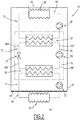
- the air conditioning device 10 is of the doubly indirect type.
- the air conditioning device 10 comprises, in addition to the primary circuit 12, in which the refrigerant circulates, two intermediate circuits, called first secondary circuit 14 and second secondary circuit 16, said refrigerant exchanging heat with water. air through these secondary circuits 14, 16.
- the first secondary circuit 14 is substantially identical to that which has been described with reference to figure 1 .
- the second secondary circuit 16 in which a second fluid circulates, passes through the condenser 20, so that the second fluid exchanges its heat there with the refrigerant of the primary circuit 12.
- This second secondary circuit 16 also comprises at least one second heat exchanger 36, in which the second fluid exchanges its heat with the outside air, and a second pump 38 to drive the second fluid circulating in this second secondary circuit 16.
- the second secondary circuit 16 further comprises pipes 40 connecting in series the second heat exchanger 36, the condenser 20 and the second pump 38, so as to form a loop.
- the second heat exchanger 36 communicates with outside air, which then forms a hot source for the air conditioning device 10.
- the first and second fluids circulating respectively in the first 14 and second 16 secondary circuits are liquids of high calorific capacity and of high density, to reduce the volume of fluid necessary to ensure heat exchange.
- These liquids have a low pressure drop, in particular at low temperature so as not to be too viscous, and a low freezing point, ideally less than -40 ° C, or at least less than -20 ° C, so as not to freeze in winter.
- the first and second fluids are mixtures of monoethylene glycol and water, or mixtures of the “TIFOXIT” type.
- the cycle of the refrigerant in the primary circuit 12 is conventional and known per se.
- the refrigerant At the inlet of the compressor 18, the refrigerant is generally in the gas phase.
- the refrigerant is compressed there (its pressure typically drops from 3 bars to 20 bars) and becomes very hot, of the order of 60 ° C.
- the refrigerant cools and then condenses. It then changes from a gas phase to a liquid phase, without changing temperature. On leaving this condenser 20, the refrigerant is in the liquid phase, at high temperature and at high pressure.
- the refrigerant then passes through the expansion member 22, and expands adiabatically. It cools, until its pressure returns to 3 bars and its temperature is around 0 ° C. The refrigerant then forms a liquid / gas mixture which then passes through the evaporator 24.
- the refrigerant is heated by capturing the heat of the first fluid which circulates in the first secondary circuit 14. The refrigerant then changes phase and becomes completely gaseous again before entering the compressor 18 again.
- the first fluid takes calories from the air to be conditioned (cold source) in the first heat exchanger 30, then supplies these calories to the refrigerant in the evaporator 24.
- the second fluid takes calories from the refrigerant in the condenser 20, then supplies these calories to the outside air (hot source) in the second heat exchanger 36.
- the evaporator 24 and the condenser 20 are intended for exchanges with, respectively, the first and second fluids, rather than with air, and therefore require a smaller heat exchange surface.
- This evaporator 24 and this condenser 20 therefore have a smaller footprint than evaporators and condensers provided for heat exchange with air.
- the evaporator 24 and the condenser 20 can be arranged as close as possible to the compressor 18, which makes it possible to reduce the length of the pipes 26, and to limit the size of the primary circuit 12 as a whole.
- each pipe 26 is less than 50 cm.
- the primary circuit 12 contains a smaller quantity of refrigerant, generally less than 4 kg, or even less than 2 kg.
- the first pump 32 and the second pump 38 are both housed in the compartment 42.
- at least one of these pumps, for example the first pump 32 could be housed outside the compartment 42, for example. example in the air treatment zone 44.
- the second heat exchanger 36 can be housed inside the compartment 42.
- a grid 48 is provided opposite the second heat exchanger 36, to allow the communication of this second heat exchanger. 36 with outside air.
- the second heat exchanger 36 can be arranged outside the compartment 42.
- the compactness of the primary circuit 12 makes it possible to limit the risk of leaks.
- the risks of the sealed wall 46 yielding under the pressure of refrigerant which has leaked in the compartment 42 are very limited.
- the sealed wall 46 is sufficient to prevent refrigerant leaks from the compartment 42 to the air treatment zone 44.
- the common support 28 is removable from this compartment 42.
- the primary circuit 12 can be easily dismantled for maintenance reasons, simply by disconnecting the pipes 34 from the first secondary circuit. of the evaporator 24, and the pipes 40 of the second secondary circuit 16 of the condenser 20.
- the air conditioning device could include a more complex primary circuit, comprising several channels and valves to alternately connect the condenser 20 to the first secondary circuit 14 and the evaporator 24 to the second secondary circuit 16, and thus reverse the hot and cold sources. .
Landscapes
- Engineering & Computer Science (AREA)
- Mechanical Engineering (AREA)
- General Engineering & Computer Science (AREA)
- Physics & Mathematics (AREA)
- Thermal Sciences (AREA)
- Chemical & Material Sciences (AREA)
- Combustion & Propulsion (AREA)
- Air-Conditioning For Vehicles (AREA)
- Heat-Exchange Devices With Radiators And Conduit Assemblies (AREA)
- Cooling Or The Like Of Electrical Apparatus (AREA)
Priority Applications (1)
| Application Number | Priority Date | Filing Date | Title |
|---|---|---|---|
| PL13183416T PL2708436T5 (pl) | 2012-09-13 | 2013-09-06 | Urządzenie klimatyzacyjne, zwłaszcza do pojazdu szynowego |
Applications Claiming Priority (1)
| Application Number | Priority Date | Filing Date | Title |
|---|---|---|---|
| FR1258595A FR2995389B1 (fr) | 2012-09-13 | 2012-09-13 | Dispositif de climatisation d'air, notamment pour un vehicule ferroviaire |
Publications (3)
| Publication Number | Publication Date |
|---|---|
| EP2708436A1 EP2708436A1 (fr) | 2014-03-19 |
| EP2708436B1 EP2708436B1 (fr) | 2018-12-05 |
| EP2708436B2 true EP2708436B2 (fr) | 2021-11-24 |
Family
ID=47089029
Family Applications (1)
| Application Number | Title | Priority Date | Filing Date |
|---|---|---|---|
| EP13183416.0A Active EP2708436B2 (fr) | 2012-09-13 | 2013-09-06 | Véhicule ferroviaire comprenant un habitacle et un dispositif de climatisation |
Country Status (9)
| Country | Link |
|---|---|
| US (2) | US20140069135A1 (es) |
| EP (1) | EP2708436B2 (es) |
| CN (1) | CN103661457A (es) |
| BR (1) | BR102013023450B1 (es) |
| ES (1) | ES2714309T5 (es) |
| FR (1) | FR2995389B1 (es) |
| PL (1) | PL2708436T5 (es) |
| RU (1) | RU2643860C2 (es) |
| TR (1) | TR201902843T4 (es) |
Families Citing this family (4)
| Publication number | Priority date | Publication date | Assignee | Title |
|---|---|---|---|---|
| CN104787066B (zh) * | 2015-03-31 | 2017-07-28 | 江苏中辆科技有限公司 | 轨道车辆的空调系统 |
| DE102016011051A1 (de) | 2016-09-12 | 2018-03-15 | Liebherr-Transportation Systems Gmbh | Klimaanlage für ein Fahrzeug und Verfahren zu deren Betrieb |
| FR3085468B1 (fr) * | 2018-09-03 | 2020-12-18 | Arkema France | Procede de conditionnement d'air |
| WO2021180404A1 (de) * | 2020-03-09 | 2021-09-16 | Siemens Mobility GmbH | Klimaanordnung und damit ausgestattetes fahrzeug zur personenbeförderung |
Citations (3)
| Publication number | Priority date | Publication date | Assignee | Title |
|---|---|---|---|---|
| US5265437A (en) † | 1990-11-26 | 1993-11-30 | Modine Manufacturing Co. | Automotive refrigeration system requiring minimal refrigerant |
| US6457324B2 (en) † | 1998-05-22 | 2002-10-01 | Bergstrom, Inc. | Modular low-pressure delivery vehicle air conditioning system having an in-cab cool box |
| US20080245503A1 (en) † | 2007-04-09 | 2008-10-09 | Wilson Michael J | Heat exchange system for vehicles and method of operating the same |
Family Cites Families (46)
| Publication number | Priority date | Publication date | Assignee | Title |
|---|---|---|---|---|
| US2205364A (en) * | 1934-05-31 | 1940-06-18 | Nash Kelvinator Corp | Refrigerating apparatus |
| US2255588A (en) * | 1939-04-27 | 1941-09-09 | Borg Warner | Method of heat transfer |
| US2534272A (en) * | 1947-12-22 | 1950-12-19 | Dole Refrigerating Co | Multitemperature refrigerator car |
| US2881600A (en) * | 1953-06-19 | 1959-04-14 | Thore M Elfving | Mechanically refrigerated railway car |
| US2791098A (en) * | 1954-05-24 | 1957-05-07 | Dole Refrigerating Co | Car refrigeration assembly with internal combustion motor |
| US2791102A (en) * | 1954-09-10 | 1957-05-07 | Dole Refrigerating Co | Refrigerated cars |
| US2990483A (en) * | 1960-02-11 | 1961-06-27 | Gen Electric | High natural frequency air shield for a dynamoelectric machine |
| US3460859A (en) * | 1967-03-23 | 1969-08-12 | Henry M Keating | Duct coupling frame and corner member |
| US3605534A (en) * | 1967-05-24 | 1971-09-20 | William H Barr | Board cutting machine |
| US3550522A (en) * | 1969-01-29 | 1970-12-29 | Edward J Bauer | Telescopic,portable temperature control unit for the rear seat portion of an automobile |
| US3611743A (en) * | 1969-11-19 | 1971-10-12 | Anthony J Manganaro | Room air conditioner |
| AT321351B (de) * | 1973-04-13 | 1975-03-25 | Friedmann Kg Alex | Klimaanlage, insbesondere für Eisenbahnfahrzeuge |
| NL8003375A (nl) * | 1980-06-10 | 1982-01-04 | Jozef Herman Hoevels | Inrichting voor het koelen van gesloten of open ruimten in bijvoorbeeld voertuigen. |
| KR960007043B1 (ko) * | 1987-04-30 | 1996-05-27 | 가부시기가이샤 히다찌 세이사꾸쇼 | 철도차량용 공기조화장치 |
| US4979431A (en) * | 1988-11-08 | 1990-12-25 | Mitsui O. S. K. Lines, Ltd. | Gaseous flow construction of box member for refrigerated transportion and box member for refrigerated transportation using the same |
| FR2646500B1 (fr) * | 1989-04-27 | 1994-11-25 | Alsthom Gec | Procede de refroidissement de composants electriques, dispositif pour la mise en oeuvre de ce procede et application aux composants embarques dans un vehicule |
| TW224512B (es) * | 1992-03-19 | 1994-06-01 | Mitsubishi Rayon Co | |
| JP3414825B2 (ja) * | 1994-03-30 | 2003-06-09 | 東芝キヤリア株式会社 | 空気調和装置 |
| JPH08189713A (ja) * | 1995-01-13 | 1996-07-23 | Daikin Ind Ltd | 二元冷凍装置 |
| JP3063742B2 (ja) * | 1998-01-30 | 2000-07-12 | ダイキン工業株式会社 | 冷凍装置 |
| US6038877A (en) * | 1998-05-22 | 2000-03-21 | Bergstrom, Inc. | Modular low pressure delivery vehicle air conditioning system |
| AT406363B (de) * | 1998-06-10 | 2000-04-25 | Integral Verkehrstechnik Ag | Fahrzeug, insbesondere schienenfahrzeug |
| DE19840136A1 (de) * | 1998-09-03 | 2000-03-09 | Volkswagen Ag | Halterungselement und Halterung für starre Leitungen in einem Fahrzeug |
| US7823626B2 (en) | 2001-10-15 | 2010-11-02 | Whirlpool Corporation | Refrigerated oven |
| US6763669B1 (en) * | 2003-05-05 | 2004-07-20 | Carrier Corporation | Modular air conditioner for a bus rooftop |
| JP2004351985A (ja) * | 2003-05-27 | 2004-12-16 | Sanden Corp | 車両用空調装置 |
| JP5452845B2 (ja) * | 2004-01-28 | 2014-03-26 | ブルックス オートメーション インコーポレイテッド | 混合不活性成分冷媒を使用する冷媒サイクル |
| JP2006029744A (ja) * | 2004-07-21 | 2006-02-02 | Hachiyo Engneering Kk | 集中式空気調和装置 |
| JP2006044424A (ja) | 2004-08-03 | 2006-02-16 | Sanden Corp | 車両用空調装置 |
| JP2006078090A (ja) * | 2004-09-09 | 2006-03-23 | Sanden Corp | 冷凍装置 |
| KR100758902B1 (ko) * | 2004-11-23 | 2007-09-14 | 엘지전자 주식회사 | 멀티 공기조화 시스템 및 그 제어방법 |
| WO2007073391A1 (en) * | 2005-12-20 | 2007-06-28 | Carrier Corporation | Integrated transport refrigeration unit with limited heat transfer and quick mount housing |
| JP4165566B2 (ja) * | 2006-01-25 | 2008-10-15 | ダイキン工業株式会社 | 空気調和装置 |
| JP4842022B2 (ja) * | 2006-06-14 | 2011-12-21 | サンデン株式会社 | 蒸気圧縮式冷凍回路及び当該回路を用いた車両用空調システム |
| FR2902864B1 (fr) * | 2006-06-27 | 2008-09-26 | Eurocave Sa | Dispositif de climatisation pour piece a ambiance controlee, notamment cave a vin, et son utilisation |
| DE102006047367B4 (de) * | 2006-10-06 | 2009-01-15 | Konvekta Ag | Klima- oder / und Heizungsanlage mit zusammengesetztem Gehäuse |
| DE102007035110A1 (de) * | 2007-07-20 | 2009-01-22 | Visteon Global Technologies Inc., Van Buren | Klimaanlage für Kraftfahrzeuge und Verfahren zu ihrem Betrieb |
| JP2012117769A (ja) * | 2010-12-02 | 2012-06-21 | Panasonic Corp | 冷温水給湯装置 |
| DE202014010264U1 (de) * | 2014-01-09 | 2015-02-25 | Siemens Aktiengesellschaft | Fahrzeug mit einer Kompressionskältemaschine |
| DE102015112030A1 (de) * | 2015-07-23 | 2017-01-26 | Halla Visteon Climate Control Corporation | Modulares Klimatisierungssystem eines Kraftfahrzeugs |
| US10267546B2 (en) * | 2015-09-04 | 2019-04-23 | Ford Global Technologies Llc | Vehicle HVAC system with combination heat exchanger for heating and cooling vehicle interior |
| EP3385587B1 (en) * | 2015-12-03 | 2023-08-02 | Mitsubishi Electric Corporation | Elastic body for closure, air conditioning device, and closure method |
| US10454334B2 (en) * | 2016-04-22 | 2019-10-22 | Hanon Systems | Compressor |
| FR3055252B1 (fr) * | 2016-09-01 | 2020-03-13 | Alstom Transport Technologies | Systeme de traitement d'air pour un vehicule de transport terrestre, vehicule comprenant un tel systeme, et procede de traitement d'air |
| WO2018045013A1 (en) * | 2016-09-02 | 2018-03-08 | Segame Technologies Llc | Vehicle thermal management system and heat exchangers |
| GB2559748B (en) * | 2017-02-16 | 2019-12-04 | Ford Global Tech Llc | An air conditioning system connector |
-
2012
- 2012-09-13 FR FR1258595A patent/FR2995389B1/fr not_active Expired - Fee Related
-
2013
- 2013-09-06 ES ES13183416T patent/ES2714309T5/es active Active
- 2013-09-06 EP EP13183416.0A patent/EP2708436B2/fr active Active
- 2013-09-06 PL PL13183416T patent/PL2708436T5/pl unknown
- 2013-09-06 TR TR2019/02843T patent/TR201902843T4/tr unknown
- 2013-09-11 US US14/024,519 patent/US20140069135A1/en not_active Abandoned
- 2013-09-12 BR BR102013023450-8A patent/BR102013023450B1/pt active IP Right Grant
- 2013-09-12 RU RU2013141924A patent/RU2643860C2/ru active
- 2013-09-13 CN CN201310415630.0A patent/CN103661457A/zh active Pending
-
2018
- 2018-06-22 US US16/016,120 patent/US20180306453A1/en not_active Abandoned
Patent Citations (3)
| Publication number | Priority date | Publication date | Assignee | Title |
|---|---|---|---|---|
| US5265437A (en) † | 1990-11-26 | 1993-11-30 | Modine Manufacturing Co. | Automotive refrigeration system requiring minimal refrigerant |
| US6457324B2 (en) † | 1998-05-22 | 2002-10-01 | Bergstrom, Inc. | Modular low-pressure delivery vehicle air conditioning system having an in-cab cool box |
| US20080245503A1 (en) † | 2007-04-09 | 2008-10-09 | Wilson Michael J | Heat exchange system for vehicles and method of operating the same |
Also Published As
| Publication number | Publication date |
|---|---|
| RU2643860C2 (ru) | 2018-02-06 |
| PL2708436T5 (pl) | 2022-02-14 |
| ES2714309T5 (es) | 2022-03-23 |
| BR102013023450A2 (pt) | 2014-12-09 |
| US20140069135A1 (en) | 2014-03-13 |
| ES2714309T3 (es) | 2019-05-28 |
| BR102013023450A8 (pt) | 2016-05-31 |
| RU2013141924A (ru) | 2015-03-20 |
| BR102013023450B1 (pt) | 2022-02-15 |
| FR2995389A1 (fr) | 2014-03-14 |
| CN103661457A (zh) | 2014-03-26 |
| EP2708436A1 (fr) | 2014-03-19 |
| EP2708436B1 (fr) | 2018-12-05 |
| PL2708436T3 (pl) | 2019-05-31 |
| US20180306453A1 (en) | 2018-10-25 |
| FR2995389B1 (fr) | 2017-10-20 |
| TR201902843T4 (tr) | 2019-03-21 |
Similar Documents
| Publication | Publication Date | Title |
|---|---|---|
| EP2708436B2 (fr) | Véhicule ferroviaire comprenant un habitacle et un dispositif de climatisation | |
| EP0415840B1 (fr) | Condenseur avec réservoir/refroidisseur secondaire | |
| CN101910758B (zh) | 压力释放装置在高压致冷系统中的固定 | |
| FR3020130A1 (fr) | Circuit de fluide frigorigene | |
| FR2963665A1 (fr) | Boucle de climatisation comprenant un dispositif de reception d'un fluide refrigerant | |
| US20060260354A1 (en) | Refrigeration cycle apparatus | |
| JP6056657B2 (ja) | 配管接続装置及びこれを有するヒートポンプサイクル装置 | |
| FR3073040A1 (fr) | Dispositifs de securite pour installations aerauliques de froid et pompes a chaleur utilisant des fluides frigorigenes toxiques ou inflammables | |
| EP0978693B1 (en) | Refrigerating system using a refrigerant of defined specific volume | |
| EP3627077A1 (en) | Refrigerant recovery apparatus | |
| EP2216612B1 (fr) | Dispositif de stockage présentant un moyen destiné à provoquer des turbulences. | |
| EP2336682A2 (fr) | Bloc de distribution d'un fluide réfrigérant circulant à l'intérieur d'une boucle de climatisation et boucle de climatisation comprenant un tel bloc de distribution | |
| CA2598277A1 (en) | Refrigerant cycle with three-way service valve for environmentally friendly refrigerant | |
| EP1817190A1 (fr) | Refroidisseur de gaz pour un circuit de climatisation de véhicule automobile | |
| FR2792063A1 (fr) | Turboventilateur mu par la detente d'un liquide ou d'un gaz frigorigene dans un systeme frigorifique ou de climatisation | |
| FR3061867A1 (fr) | Boucle de circulation d'un fluide refrigerant pour le conditionnement d'air d'habitacle d'un vehicule | |
| JP2008196731A (ja) | 冷凍装置 | |
| WO2015104330A1 (fr) | Pompe à chaleur produisant du froid | |
| WO2021037966A1 (en) | Common unit for refrigerant gas handling system | |
| FR2979287A1 (fr) | Circuit de fluide refrigerant a deux etages de compression et bouteille a pression intermediaire | |
| FR3051547B1 (fr) | Systeme et procede de conditionnement d'air pour un compartiment, notamment un habitacle de vehicule automobile | |
| JP2004324949A (ja) | 冷媒回路及びそれを備えた冷凍機 | |
| FR3014755A1 (fr) | Circuit de fluide frigorigene pour le conditionnement thermique d'un vehicule automobile | |
| WO2012065972A1 (fr) | Boucle de climatisation munie d'électrovanne et fonctionnant comme pompe à chaleur. | |
| EP3606775B1 (fr) | Installation de ventilation, chauffage et/ou climatisation comprenant une arrivee d'air additionnelle |
Legal Events
| Date | Code | Title | Description |
|---|---|---|---|
| PUAI | Public reference made under article 153(3) epc to a published international application that has entered the european phase |
Free format text: ORIGINAL CODE: 0009012 |
|
| AK | Designated contracting states |
Kind code of ref document: A1 Designated state(s): AL AT BE BG CH CY CZ DE DK EE ES FI FR GB GR HR HU IE IS IT LI LT LU LV MC MK MT NL NO PL PT RO RS SE SI SK SM TR |
|
| AX | Request for extension of the european patent |
Extension state: BA ME |
|
| 17P | Request for examination filed |
Effective date: 20140919 |
|
| RBV | Designated contracting states (corrected) |
Designated state(s): AL AT BE BG CH CY CZ DE DK EE ES FI FR GB GR HR HU IE IS IT LI LT LU LV MC MK MT NL NO PL PT RO RS SE SI SK SM TR |
|
| RIN1 | Information on inventor provided before grant (corrected) |
Inventor name: MORTREUX, FRANCIS |
|
| RAP1 | Party data changed (applicant data changed or rights of an application transferred) |
Owner name: ALSTOM TRANSPORT TECHNOLOGIES |
|
| RAP1 | Party data changed (applicant data changed or rights of an application transferred) |
Owner name: ALSTOM TRANSPORT TECHNOLOGIES |
|
| GRAP | Despatch of communication of intention to grant a patent |
Free format text: ORIGINAL CODE: EPIDOSNIGR1 |
|
| STAA | Information on the status of an ep patent application or granted ep patent |
Free format text: STATUS: GRANT OF PATENT IS INTENDED |
|
| INTG | Intention to grant announced |
Effective date: 20180626 |
|
| GRAS | Grant fee paid |
Free format text: ORIGINAL CODE: EPIDOSNIGR3 |
|
| GRAA | (expected) grant |
Free format text: ORIGINAL CODE: 0009210 |
|
| STAA | Information on the status of an ep patent application or granted ep patent |
Free format text: STATUS: THE PATENT HAS BEEN GRANTED |
|
| AK | Designated contracting states |
Kind code of ref document: B1 Designated state(s): AL AT BE BG CH CY CZ DE DK EE ES FI FR GB GR HR HU IE IS IT LI LT LU LV MC MK MT NL NO PL PT RO RS SE SI SK SM TR |
|
| REG | Reference to a national code |
Ref country code: GB Ref legal event code: FG4D Free format text: NOT ENGLISH |
|
| REG | Reference to a national code |
Ref country code: CH Ref legal event code: EP |
|
| REG | Reference to a national code |
Ref country code: AT Ref legal event code: REF Ref document number: 1072647 Country of ref document: AT Kind code of ref document: T Effective date: 20181215 |
|
| REG | Reference to a national code |
Ref country code: IE Ref legal event code: FG4D Free format text: LANGUAGE OF EP DOCUMENT: FRENCH |
|
| REG | Reference to a national code |
Ref country code: DE Ref legal event code: R096 Ref document number: 602013047695 Country of ref document: DE |
|
| REG | Reference to a national code |
Ref country code: CH Ref legal event code: NV Representative=s name: MICHELI AND CIE SA, CH |
|
| REG | Reference to a national code |
Ref country code: NL Ref legal event code: MP Effective date: 20181205 |
|
| REG | Reference to a national code |
Ref country code: LT Ref legal event code: MG4D |
|
| PG25 | Lapsed in a contracting state [announced via postgrant information from national office to epo] |
Ref country code: BG Free format text: LAPSE BECAUSE OF FAILURE TO SUBMIT A TRANSLATION OF THE DESCRIPTION OR TO PAY THE FEE WITHIN THE PRESCRIBED TIME-LIMIT Effective date: 20190305 Ref country code: NO Free format text: LAPSE BECAUSE OF FAILURE TO SUBMIT A TRANSLATION OF THE DESCRIPTION OR TO PAY THE FEE WITHIN THE PRESCRIBED TIME-LIMIT Effective date: 20190305 Ref country code: HR Free format text: LAPSE BECAUSE OF FAILURE TO SUBMIT A TRANSLATION OF THE DESCRIPTION OR TO PAY THE FEE WITHIN THE PRESCRIBED TIME-LIMIT Effective date: 20181205 Ref country code: LT Free format text: LAPSE BECAUSE OF FAILURE TO SUBMIT A TRANSLATION OF THE DESCRIPTION OR TO PAY THE FEE WITHIN THE PRESCRIBED TIME-LIMIT Effective date: 20181205 Ref country code: LV Free format text: LAPSE BECAUSE OF FAILURE TO SUBMIT A TRANSLATION OF THE DESCRIPTION OR TO PAY THE FEE WITHIN THE PRESCRIBED TIME-LIMIT Effective date: 20181205 Ref country code: FI Free format text: LAPSE BECAUSE OF FAILURE TO SUBMIT A TRANSLATION OF THE DESCRIPTION OR TO PAY THE FEE WITHIN THE PRESCRIBED TIME-LIMIT Effective date: 20181205 |
|
| REG | Reference to a national code |
Ref country code: ES Ref legal event code: FG2A Ref document number: 2714309 Country of ref document: ES Kind code of ref document: T3 Effective date: 20190528 |
|
| PG25 | Lapsed in a contracting state [announced via postgrant information from national office to epo] |
Ref country code: RS Free format text: LAPSE BECAUSE OF FAILURE TO SUBMIT A TRANSLATION OF THE DESCRIPTION OR TO PAY THE FEE WITHIN THE PRESCRIBED TIME-LIMIT Effective date: 20181205 Ref country code: AL Free format text: LAPSE BECAUSE OF FAILURE TO SUBMIT A TRANSLATION OF THE DESCRIPTION OR TO PAY THE FEE WITHIN THE PRESCRIBED TIME-LIMIT Effective date: 20181205 Ref country code: SE Free format text: LAPSE BECAUSE OF FAILURE TO SUBMIT A TRANSLATION OF THE DESCRIPTION OR TO PAY THE FEE WITHIN THE PRESCRIBED TIME-LIMIT Effective date: 20181205 Ref country code: GR Free format text: LAPSE BECAUSE OF FAILURE TO SUBMIT A TRANSLATION OF THE DESCRIPTION OR TO PAY THE FEE WITHIN THE PRESCRIBED TIME-LIMIT Effective date: 20190306 |
|
| PG25 | Lapsed in a contracting state [announced via postgrant information from national office to epo] |
Ref country code: NL Free format text: LAPSE BECAUSE OF FAILURE TO SUBMIT A TRANSLATION OF THE DESCRIPTION OR TO PAY THE FEE WITHIN THE PRESCRIBED TIME-LIMIT Effective date: 20181205 |
|
| PG25 | Lapsed in a contracting state [announced via postgrant information from national office to epo] |
Ref country code: PT Free format text: LAPSE BECAUSE OF FAILURE TO SUBMIT A TRANSLATION OF THE DESCRIPTION OR TO PAY THE FEE WITHIN THE PRESCRIBED TIME-LIMIT Effective date: 20190405 |
|
| REG | Reference to a national code |
Ref country code: DE Ref legal event code: R026 Ref document number: 602013047695 Country of ref document: DE |
|
| PLBI | Opposition filed |
Free format text: ORIGINAL CODE: 0009260 |
|
| PG25 | Lapsed in a contracting state [announced via postgrant information from national office to epo] |
Ref country code: RO Free format text: LAPSE BECAUSE OF FAILURE TO SUBMIT A TRANSLATION OF THE DESCRIPTION OR TO PAY THE FEE WITHIN THE PRESCRIBED TIME-LIMIT Effective date: 20181205 Ref country code: IS Free format text: LAPSE BECAUSE OF FAILURE TO SUBMIT A TRANSLATION OF THE DESCRIPTION OR TO PAY THE FEE WITHIN THE PRESCRIBED TIME-LIMIT Effective date: 20190405 Ref country code: SM Free format text: LAPSE BECAUSE OF FAILURE TO SUBMIT A TRANSLATION OF THE DESCRIPTION OR TO PAY THE FEE WITHIN THE PRESCRIBED TIME-LIMIT Effective date: 20181205 Ref country code: EE Free format text: LAPSE BECAUSE OF FAILURE TO SUBMIT A TRANSLATION OF THE DESCRIPTION OR TO PAY THE FEE WITHIN THE PRESCRIBED TIME-LIMIT Effective date: 20181205 Ref country code: SK Free format text: LAPSE BECAUSE OF FAILURE TO SUBMIT A TRANSLATION OF THE DESCRIPTION OR TO PAY THE FEE WITHIN THE PRESCRIBED TIME-LIMIT Effective date: 20181205 |
|
| PLAX | Notice of opposition and request to file observation + time limit sent |
Free format text: ORIGINAL CODE: EPIDOSNOBS2 |
|
| PLAX | Notice of opposition and request to file observation + time limit sent |
Free format text: ORIGINAL CODE: EPIDOSNOBS2 |
|
| 26 | Opposition filed |
Opponent name: KONVEKTA AKTIENGESELLSCHAFT Effective date: 20190820 |
|
| PG25 | Lapsed in a contracting state [announced via postgrant information from national office to epo] |
Ref country code: DK Free format text: LAPSE BECAUSE OF FAILURE TO SUBMIT A TRANSLATION OF THE DESCRIPTION OR TO PAY THE FEE WITHIN THE PRESCRIBED TIME-LIMIT Effective date: 20181205 Ref country code: SI Free format text: LAPSE BECAUSE OF FAILURE TO SUBMIT A TRANSLATION OF THE DESCRIPTION OR TO PAY THE FEE WITHIN THE PRESCRIBED TIME-LIMIT Effective date: 20181205 |
|
| PLBB | Reply of patent proprietor to notice(s) of opposition received |
Free format text: ORIGINAL CODE: EPIDOSNOBS3 |
|
| PG25 | Lapsed in a contracting state [announced via postgrant information from national office to epo] |
Ref country code: MC Free format text: LAPSE BECAUSE OF FAILURE TO SUBMIT A TRANSLATION OF THE DESCRIPTION OR TO PAY THE FEE WITHIN THE PRESCRIBED TIME-LIMIT Effective date: 20181205 |
|
| PG25 | Lapsed in a contracting state [announced via postgrant information from national office to epo] |
Ref country code: LU Free format text: LAPSE BECAUSE OF NON-PAYMENT OF DUE FEES Effective date: 20190906 Ref country code: IE Free format text: LAPSE BECAUSE OF NON-PAYMENT OF DUE FEES Effective date: 20190906 |
|
| REG | Reference to a national code |
Ref country code: BE Ref legal event code: MM Effective date: 20190930 |
|
| PG25 | Lapsed in a contracting state [announced via postgrant information from national office to epo] |
Ref country code: BE Free format text: LAPSE BECAUSE OF NON-PAYMENT OF DUE FEES Effective date: 20190930 |
|
| REG | Reference to a national code |
Ref country code: AT Ref legal event code: UEP Ref document number: 1072647 Country of ref document: AT Kind code of ref document: T Effective date: 20181205 |
|
| PG25 | Lapsed in a contracting state [announced via postgrant information from national office to epo] |
Ref country code: CY Free format text: LAPSE BECAUSE OF FAILURE TO SUBMIT A TRANSLATION OF THE DESCRIPTION OR TO PAY THE FEE WITHIN THE PRESCRIBED TIME-LIMIT Effective date: 20181205 |
|
| PG25 | Lapsed in a contracting state [announced via postgrant information from national office to epo] |
Ref country code: HU Free format text: LAPSE BECAUSE OF FAILURE TO SUBMIT A TRANSLATION OF THE DESCRIPTION OR TO PAY THE FEE WITHIN THE PRESCRIBED TIME-LIMIT; INVALID AB INITIO Effective date: 20130906 Ref country code: MT Free format text: LAPSE BECAUSE OF FAILURE TO SUBMIT A TRANSLATION OF THE DESCRIPTION OR TO PAY THE FEE WITHIN THE PRESCRIBED TIME-LIMIT Effective date: 20181205 |
|
| REG | Reference to a national code |
Ref country code: CH Ref legal event code: PK Free format text: TITRE |
|
| PUAH | Patent maintained in amended form |
Free format text: ORIGINAL CODE: 0009272 |
|
| STAA | Information on the status of an ep patent application or granted ep patent |
Free format text: STATUS: PATENT MAINTAINED AS AMENDED |
|
| 27A | Patent maintained in amended form |
Effective date: 20211124 |
|
| AK | Designated contracting states |
Kind code of ref document: B2 Designated state(s): AL AT BE BG CH CY CZ DE DK EE ES FI FR GB GR HR HU IE IS IT LI LT LU LV MC MK MT NL NO PL PT RO RS SE SI SK SM TR |
|
| REG | Reference to a national code |
Ref country code: DE Ref legal event code: R102 Ref document number: 602013047695 Country of ref document: DE |
|
| REG | Reference to a national code |
Ref country code: ES Ref legal event code: DC2A Ref document number: 2714309 Country of ref document: ES Kind code of ref document: T5 Effective date: 20220323 |
|
| PG25 | Lapsed in a contracting state [announced via postgrant information from national office to epo] |
Ref country code: MK Free format text: LAPSE BECAUSE OF FAILURE TO SUBMIT A TRANSLATION OF THE DESCRIPTION OR TO PAY THE FEE WITHIN THE PRESCRIBED TIME-LIMIT Effective date: 20181205 |
|
| P01 | Opt-out of the competence of the unified patent court (upc) registered |
Effective date: 20230823 |
|
| PGFP | Annual fee paid to national office [announced via postgrant information from national office to epo] |
Ref country code: TR Payment date: 20230905 Year of fee payment: 11 Ref country code: GB Payment date: 20230920 Year of fee payment: 11 Ref country code: CZ Payment date: 20230828 Year of fee payment: 11 Ref country code: AT Payment date: 20230921 Year of fee payment: 11 |
|
| PGFP | Annual fee paid to national office [announced via postgrant information from national office to epo] |
Ref country code: PL Payment date: 20230824 Year of fee payment: 11 Ref country code: FR Payment date: 20230928 Year of fee payment: 11 Ref country code: DE Payment date: 20230920 Year of fee payment: 11 |
|
| PGFP | Annual fee paid to national office [announced via postgrant information from national office to epo] |
Ref country code: ES Payment date: 20231124 Year of fee payment: 11 |
|
| PGFP | Annual fee paid to national office [announced via postgrant information from national office to epo] |
Ref country code: IT Payment date: 20230927 Year of fee payment: 11 Ref country code: CH Payment date: 20231001 Year of fee payment: 11 |