EP2708039B1 - Room characterization and correction for multi-channel audio - Google Patents
Room characterization and correction for multi-channel audio Download PDFInfo
- Publication number
- EP2708039B1 EP2708039B1 EP12782597.4A EP12782597A EP2708039B1 EP 2708039 B1 EP2708039 B1 EP 2708039B1 EP 12782597 A EP12782597 A EP 12782597A EP 2708039 B1 EP2708039 B1 EP 2708039B1
- Authority
- EP
- European Patent Office
- Prior art keywords
- room
- frequency
- acoustic
- responses
- computing
- Prior art date
- Legal status (The legal status is an assumption and is not a legal conclusion. Google has not performed a legal analysis and makes no representation as to the accuracy of the status listed.)
- Active
Links
Images


Classifications
-
- H—ELECTRICITY
- H04—ELECTRIC COMMUNICATION TECHNIQUE
- H04S—STEREOPHONIC SYSTEMS
- H04S7/00—Indicating arrangements; Control arrangements, e.g. balance control
- H04S7/30—Control circuits for electronic adaptation of the sound field
- H04S7/302—Electronic adaptation of stereophonic sound system to listener position or orientation
- H04S7/303—Tracking of listener position or orientation
-
- H—ELECTRICITY
- H04—ELECTRIC COMMUNICATION TECHNIQUE
- H04R—LOUDSPEAKERS, MICROPHONES, GRAMOPHONE PICK-UPS OR LIKE ACOUSTIC ELECTROMECHANICAL TRANSDUCERS; ELECTRIC HEARING AIDS; PUBLIC ADDRESS SYSTEMS
- H04R5/00—Stereophonic arrangements
- H04R5/02—Spatial or constructional arrangements of loudspeakers
-
- H—ELECTRICITY
- H04—ELECTRIC COMMUNICATION TECHNIQUE
- H04S—STEREOPHONIC SYSTEMS
- H04S7/00—Indicating arrangements; Control arrangements, e.g. balance control
- H04S7/30—Control circuits for electronic adaptation of the sound field
- H04S7/301—Automatic calibration of stereophonic sound system, e.g. with test microphone
-
- H—ELECTRICITY
- H04—ELECTRIC COMMUNICATION TECHNIQUE
- H04R—LOUDSPEAKERS, MICROPHONES, GRAMOPHONE PICK-UPS OR LIKE ACOUSTIC ELECTROMECHANICAL TRANSDUCERS; ELECTRIC HEARING AIDS; PUBLIC ADDRESS SYSTEMS
- H04R3/00—Circuits for transducers
- H04R3/005—Circuits for transducers for combining the signals of two or more microphones
-
- H—ELECTRICITY
- H04—ELECTRIC COMMUNICATION TECHNIQUE
- H04S—STEREOPHONIC SYSTEMS
- H04S2400/00—Details of stereophonic systems covered by H04S but not provided for in its groups
- H04S2400/01—Multi-channel, i.e. more than two input channels, sound reproduction with two speakers wherein the multi-channel information is substantially preserved
-
- H—ELECTRICITY
- H04—ELECTRIC COMMUNICATION TECHNIQUE
- H04S—STEREOPHONIC SYSTEMS
- H04S2420/00—Techniques used stereophonic systems covered by H04S but not provided for in its groups
- H04S2420/01—Enhancing the perception of the sound image or of the spatial distribution using head related transfer functions [HRTF's] or equivalents thereof, e.g. interaural time difference [ITD] or interaural level difference [ILD]
-
- H—ELECTRICITY
- H04—ELECTRIC COMMUNICATION TECHNIQUE
- H04S—STEREOPHONIC SYSTEMS
- H04S3/00—Systems employing more than two channels, e.g. quadraphonic
- H04S3/008—Systems employing more than two channels, e.g. quadraphonic in which the audio signals are in digital form, i.e. employing more than two discrete digital channels
Definitions
- This invention is directed to a multi-channel audio playback device and method, and more particularly to a device and method adapted to characterize a multi-channel loudspeaker configuration and correct loudspeaker/room delay, gain and frequency response.
- Home entertainment systems have moved from simple stereo systems to muiti-channel audio systems, such as surround sound systems and more recently 3D sound systems, and to systems with video displays. Although these home entertainment systems have improved, room acoustics still suffer from deficiencies such as sound distortion caused by reflections from surfaces in a room and/or non-uniform placement of loudspeakers in relation to a listener. Because home entertainment systems are widely used in homes, improvement of acoustics in a room is a concern for home entertainment system users to better enjoy their preferred listening environment.
- Sound is a term used in audio engineering to refer to sound reproduction systems that use multiple channels and speakers to provide a listener positioned between the speakers with a simulated placement of sound sources. Sound can be reproduced with a different delay and at different intensities through one or more of the speakers to "surround" the listener with sound sources and thereby create a more interesting or realistic listening experience.
- a traditional surround sound system includes a two-dimensional configuration of speakers e.g. front, center, back and possibly side.
- the more recent 3D sound systems include a three-dimensional configuration of speakers. For example, the configuration may include high and low front, center, back or side speakers.
- a multi-channel speaker configuration encompasses stereo, surround sound and 3D sound systems.
- Multi-channel surround sound is employed in movie theater and home theater applications.
- the listener in a home theater is surrounded by five speakers instead of the two speakers used in a traditional home stereo system. Of the five speakers, three are placed in the front of the room, with the remaining two surround speakers located to the rear or sides (THX® dipolar) of the listening/viewing position.
- a new configuration is to use a "sound bar" that comprises multiple speakers that can simulate the surround sound experience.
- Dolby Surround ® is the original surround format, developed in the early 1970's for movie theaters. Dolby Digital ® made its debut in 1996.
- Dolby Digital® is a digital format with six discrete audio channels and overcomes certain limitations of Dolby Surround® that relies on a matrix system that combines four audio channels into two channels to be stored on the recording media.
- Dolby Digital® is also called a 5.1-channel format and was universally adopted several years ago for film-sound recording.
- Another format in use today is DTS Digital SurroundTM that offers higher audio quality than Dolby Digital® (1,411,200 versus 384,000 bits per second) as well as many different speaker configurations e.g. 5.1, 6.1, 7.1, 11.2 etc, and variations thereof e.g. 7.1 Front Wide, Front Height, Center Overhead. Side Height or Center Height.
- DTS-HD® supports seven different 7.1 channel configurations on Blu-Ray® discs.
- the audio/video preamplifier (or A/V controller or A/V receiver) handles the job of decoding the two-channel Dolby Surround®, Dolby Digital®, or DTS Digital SurroundTM or DTS-HD® signal into the respective separate channels.
- the A/V preamplifier output provides six line level signals for the left, center, right, left surround, right surround, and subwoofer channels, respectively. These separate outputs are fed to a multiple-channel power amplifier or as is the case with an integrated receiver, are internally amplified, to drive the home-theater loudspeaker system.
- the preamplifier or receiver for the loudspeaker setup have to be configured.
- the A/V preamplifier must know the specific surround sound speaker configuration in use.
- the A/V preamplifier only supports a default output configuration, if the user cannot place the 5.1 or 7.1 speakers at those locations he or she is simply out of luck.
- a few high-end A/V preamplifiers support multiple 7 .1 configurations and let the user select from a menu the appropriate configuration for the room.
- the loudness of each of the audio channels should be individually set to provide an overall balance in the volume from the loudspeakers.
- This process begins by producing a "test signal” in the form of noise sequentially from each speaker and adjusting the volume of each speaker independently at the listening/viewing position.
- the recommended tool for this task is the Sound Pressure Level (SPL) meter. This provides compensation for different loudspeaker sensitivities, listening-room acoustics, and loudspeaker placements. Other factors, such as an asymmetric listening space and/or angled viewing area, windows, archways and sloped ceilings, can make calibration much more complicated.
- U.S. patent no. 7,158,643 entitled “Auto-Calibrating Surround System” describes one approach that allows automatic and independent calibration and adjustment of the frequency, amplitude and time response of each channel of the surround sound system.
- the system generates a test signal that is played through the speakers and recorded by the microphone.
- the system processor correlates the received sound signal with the test signal and determines from the correlated signals a whitened response.
- U.S. patent publication no. US 2007/0121955 A1 entitled “Room Acoustics Correction Device” describes a similar approach.
- Document WO 92/10876 A1 describes a prefilter for an audio system comprising a loudspeaker in a room which corrects both amplitude and phase errors due to the loudspeaker by a linear phase correction filter response and corrects the amplitude response of the room whilst introducing the minimum possible amount of extra phase distortion by employing a minimum phase correction filter stage.
- a test signal generator generates a signal comprising a periodic frequency sweep with a greater phase repetition period than the frequency repetition period.
- a microphone positioned at various points in the room measures the audio signal processed by the room and loudspeaker, and a coefficient calculator derives the signal response of the room and thereby a requisite minimum phase correction to be cascaded with the linear phase correction already calculated for the loudspeaker.
- the invention provides for a method for characterizing a listening environment for playback of multichannel audio with the features of claim 1 and a device for processing multi-channel audio with the features of claim 12.
- a broadband probe signal and possibly a pre-emphasized probe signal, is or are supplied to each audio output of an A/V preamplifier of which at least a plurality are coupled to loudspeakers in a multi-channel configuration in a listening environment.
- the loudspeakers convert the probe signal to acoustic responses that are transmitted in non-overlapping time slots separated by silent periods as sound waves into the listening environment.
- sound waves are received by a multi-microphone array that converts the acoustic responses to electric response signals.
- a processor(s) deconvolves the electric response signal with the broadband probe signal to determine a room response at each microphone for the loudspeaker.
- the processor(s) compute a room energy measure from the room responses.
- the processor(s) compute a first part of the room energy measure for frequencies above a cut-off frequency as a function of sound pressure and second part of the room energy measure for frequencies below the cut-off frequency as a function of sound pressure and sound velocity.
- the sound velocity is obtained from a gradient of the sound pressure across the microphone array. If a dual-probe signal comprising both broadband and pre-emphasized probe signals is utilized, the high frequency portion of the energy measure based only on sound pressure is extracted from the broadband room response and the low frequency portion of the energy measure based on both sound pressure and sound velocity is extracted from the pre-emphasized room response.
- the dual-probe signal may be used to compute the room energy measure without the sound velocity component, in which case the pre-emphasized probe signal is used for noise shaping.
- the processor(s) blend the first and second parts of the energy measure to provide the room energy measure over the specified acoustic band.
- the room responses or room energy measure may be progressively smoothed to capture substantially the entire time response at the lowest frequencies and essentially only the direct path plus a few milliseconds of the time response at the highest frequencies.
- the processor(s) computes filter coefficients from the room energy measure, which are used to configure digital correction filters within the processor(s).
- the processor(s) may compute the filter coefficients for a channel target curve, user defined or a smoothed version of the channel energy measure, and may then adjust the filter coefficients to a common target curve, which may be user defined or an average of the channel target curves.
- the processor(s) pass audio signals through the corresponding digital correction filters and to the loudspeaker for playback into the listening environment.
- the present invention provides devices and methods adapted to characterize a multi-channel loudspeaker configuration, to correct loudspeaker/room delay, gain and frequency response or to configure sub-band domain correction filters.
- Various devices and methods are adapted to automatically locate the loudspeakers in space to determine whether an audio channel is connected, select the particular multi-channel loudspeaker configuration and position each loudspeaker within the listening environment.
- Various devices and methods are adapted to extract a perceptually appropriate energy measure that captures both sound pressure and velocity at low frequencies and is accurate over a wide listening area. The energy measure is derived from the room responses gathered by using a closely spaced non-coincident multi-microphone array placed in a single location in the listening environment and used to configure digital correction filters.
- Various devices and methods are adapted to configure sub-band correction filters for correcting the frequency response of an input multi-channel audio signal for deviations from a target response caused by, for example, room response and loudspeaker response.
- a spectral measure (such as a room spectral/energy measure) is partitioned and remapped to base-band to mimic the downsampling of the analysis filter bank.
- AR models are independently computed for each sub-band and the models' coefficients are mapped to an all-zero minimum phase filters.
- the shapes of the analysis filters are not included in the remapping.
- the sub-band filter implementation may be configured to balance MIPS, memory requirements and processing delay and can piggyback on the analysis/synthesis filter bank architecture should one already exist for other audio processing.
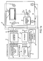
- FIG. 1a-1b , 2 and 3 depict an embodiment of a multichannel audio system 10 for probing and analyzing a multi-channel speaker configuration 12 in a listening environment 14 to automatically select the multi-channel speaker configuration and position the speakers in the room, to extract a perceptually appropriate spectral (e.g. energy) measure over a wide listening area and to configure frequency correction filters and for playback of a multi-channel audio signal 16 with room correction (delay, gain and frequency),
- Multi-channel audio signal 16 may be provided via a cable or satellite feed or may be read off a storage media such as a DVD or Blu-RayTM disc. Audio signal 16 may be paired with a video signal that is supplied to a television 18. Alternatively, audio signal 16 may be a music signal with no video signal.
- Multi-channel audio system 10 comprises an audio source 20 such as a cable or satellite receiver or DVD or Blu-RayTM player for providing multi-channel audio signal 16, an A/V preamplifier 22 that decodes the multi-channel audio signal into separate audio channels at audio outputs 24 and a plurality of loudspeakers 26 (electro-acoustic transducers) couple to respective audio outputs 24 that convert the electrical signals supplied by the A/V preamplifier to acoustic responses that are transmitted as sound waves 28 into listening environment 14 .
- Audio outputs 24 may be terminals that are hardwired to loudspeakers or wireless outputs that are wirelessly coupled to the loudspeakers. If an audio output is coupled to a loudspeaker the corresponding audio channel is said to be connected.
- the loudspeakers may be individual speakers arranged in a discrete 2D or 3D layout or sound bars each comprising multiple speakers configured to emulate a surround sound experience.
- the system also comprises a microphone assembly that includes one or more microphones 30 and a microphone transmission box 32 .
- the microphone(s) (acousto-electric transducers) receive sound waves associated with probe signals supplied to the loudspeakers and convert the acoustic response to electric signals.
- Transmission box 32 supplies the electric signals to one or more of the A/V preamplifier's audio inputs 34 through a wired or wireless connection.
- A/V preamplifier 22 comprises one or more processors 36 such as general purpose Computer Processing Units (CPUs) or dedicated Digital Signal Processor (DSP) chips that are typically provided with their own processor memory, system memory 38 and a digital-to-analog converter and amplifier 40 connected to audio outputs 24 .
- processors 36 such as general purpose Computer Processing Units (CPUs) or dedicated Digital Signal Processor (DSP) chips that are typically provided with their own processor memory, system memory 38 and a digital-to-analog converter and amplifier 40 connected to audio outputs 24 .
- the D/A converter and/or amplifier may be separate devices.
- the A/V preamplifier could output corrected digital signals to a D/A converter that outputs analog signals to a power amplifier.
- various "modules" of computer program instructions are stored in memory, processor or system, and executed by the one or more processors 36 .
- A/V preamplifier 22 also comprises an imput receiver 42 connected to the one or more audio inputs 34 to receive input microphone signals and provide separate microphone chanals to the processor(s) 36 , Microphone transmission box 32 and input receiver 42 are a matched pair.
- the transmission box 32 may comprise microphone analog preamplifiers, A/D converters and a TDM (time domain multiplexer) or A/D converters, a packer and a USB transmitter and the matched input receiver 42 may comprise an analog preamplifier and A/D converters, a SPDIF receiver and TDM demultiplexer or a USB receiver and unpacker,
- the A/V preamplifier may include an audio input 34 for each microphone signal.
- the multiple microphone signals may be multiplexed to a single signal and supplied to a single audio input 34 .
- the A/V preamplifier is provided with a probe generation and transmission scheduling module 44 and a room analysis module 46.
- module 44 generates a broadband probe signal, and possibly a paired pre-emphasized probe signal, and transmits the probe signals via A/D converter and amplifier 40 to each audio output 24 in non-overlapping time slots separated by silent periods according to a schedule. Each audio output 24 is probed whether the output is coupled to a loudspeaker or not.
- Module 44 provides the probe signal or signals and the transmission schedule to room analysis module 46 .
- module 46 processes the microphone and probe signals in accordance with the transmission schedule to automatically select the multi-channel speaker configuration and position the speakers in the room, to extract a perceptually appropriate spectra (energy) measure over a wide listening area and to configure frequency correction filters (such as sub-band frequency correction filters).
- Module 46 stores the loudspeaker configuration and speaker positions and filter coefficients in system memory 38 .
- the number and layout of microphones 30 affects the analysis module's ability to select the multi-channel loudspeaker configuration and position the loudspeakers and to extract a perceptually appropriate energy measure that is valid over a wide listening area.
- the microphone layout provides a certain amount of diversity to "localize" the loudspeakers in two or three-dimensions and to compute sound velocity.
- the microphones are non-coincident and have a fixed separation. For example, a single microphone supports estimating only the distance to the loudspeaker. A pair of microphones support estimating the distance to the loudspeaker and an angle such as the azimuth angle in half a plane (front, back or either side) and estimating the sound velocity in a single direction.
- Three microphones support estimating the distance to the loudspeaker and the azimuth angle in the entire plane (front, back and both side) and estimating the sound velocity a three-dimensional space.
- Four or more microphones positioned on a three-dimensional ball support estimating the distance to the loudspeaker and the azimuth and elevations angle a full three-dimensional space and estimating the sound velocity a three-dimensional space.
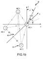
- FIG. 1b An embodiment of a multi-microphone array 48 for the case of a tetrahedral microphone array and for a specially selected coordinate system is depicted in Figure 1b .
- Four microphones 30 are placed at the vertices of a tetrahedral object ("ball") 49. All microphones are assumed to be omnidirectional i.e., the microphone signals represent the pressure measurements at different locations, Microphones 1, 2 and 3 lie in the x,y plane with microphone 1 at the origin of the coordinate system and microphones 2 and 3 equidistant from the x-axis. Microphone 4 lies out of the x,y plane. The distance between each of the microphones is equal and denoted by d.
- the direction of arrival indicates the sound wave direction of arrival (to be used for localization process in Appendix A).
- the separation of the microphones "d” represents a trade-off of reading a small separation to accurately compute sound velocity up to 500 Hz to 1 kHz and a large separation to accurately position the loudspeakers. A separation of approximately 8.5 to 9 cm satisfies both requirements.
- the A/V preamplifier is provided with an input receiver/decoder module 52 and an audio playback module 54.
- Input receiver/decoder module 52 decodes multi-channel audio signal 16 into separate audio channels.
- the multi-channel audio signal 16 may be delivered in a standard two-channel format
- Module 52 handles the job of decoding the two-channel Dolby Surround®, Dolby Digital®, or DTS Digital SurroundTM or DTS-HD® signal into the respective separate audio channels.
- Module 54 processes each audio channel to perform generalized format conversion and loudspeaker/room calibration and correction.
- module 54 may perform up or down-mixing, speaker remapping or virtualization, apply delay, gain or polarity compensation, perform bass management and perform room frequency correction.
- Module 54 may use the frequency correction parameters (e.g. delay and gain adjustments and filter coefficients) generated by the analysis mode and stored in system memory 38 to configure one or more digital frequency correction filters for each audio channel.
- the frequency correction filters may be implemented in time domain, frequency domain or sub-band domain. Each audio channel is passed through its frequency correction filter and converted to an analog audio signal that drives the loudspeaker to produce an acoustic response that is transmitted as sound waves into the listening environment
- Filter 56 comprises a P-band complex non-critically sampled analysis filter bank 58, a room frequency correction filter 60 comprising P minimum phase FIR (Finite Impulse Response) filters 62 for the P sub-bands and a P-band complex non-critically sampled synthesis filter bank 64 where P is an integer.
- room frequency correction filter 60 has been added to an existing filter architecture such as DTS NEO-XTM that performs the generalized up/mix/down-mix/speaker remapping/virtualization functions 66 in the sub-band domain.
- DTS NEO-XTM filter architecture
- the majority of computations in sub-band based room frequency correction lies in implementation of the analysis and synthesis filter banks.
- the incremental increase of processing requirements imposed by the addition of room correction to an existing sub-band architecture such as DTS NEO-XTM is minimal.
- Frequency correction is performed in sub-band domain by passing an audio signal (e.g. input PCM samples) first through oversampled analysis filter bank 58 then in each band independently applying a minimum-phase FIR correction filter 62, suitably of different lengths, and finally applying synthesis filter bank 64 to create a frequency corrected output PCM audio signal.
- an audio signal e.g. input PCM samples
- oversampled analysis filter bank 58 then in each band independently applying a minimum-phase FIR correction filter 62, suitably of different lengths, and finally applying synthesis filter bank 64 to create a frequency corrected output PCM audio signal.
- the frequency correction filters are designed to be minimum-phase the sub-band signal even after passing through different length filters are still time aligned between the bands. Consequently the delay introduced by this frequency correction approach is solely determined by the delay in the chain of analysis and synthesis filter banks. In a particular implementation with 64-band over-sampled complex filter-banks this delay is less than 20 milliseconds.
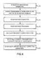
- FIG. 4 A high-level flow diagram for an embodiment of the analysis mode of operation is depicted in figure 4 .
- the analysis modules generate the broadband probe signal, and possibly a pre-emphasized probe signal transmit the probe signals in accordance with a schedule though the loudspeakers as sound waves into the listening environment and record the acoustic responses detected at the microphone array.
- the modules compute a delay and room response for each loudspeaker at each microphone and each probe signal. This processing may be done in "real time” prior to the transmission of the next probe signal or offline after all the probe signals have been transmitted and the microphone signals recorded.
- the modules process the room responses to calculate a spectral (e.g. energy) measure for each loudspeaker and, using the spectral measure, calculate frequency correction filters and gain adjustments.
- a spectral e.g. energy
- the modules use the computed delays to each loudspeaker to determining a distance and at least an azimuth angle to the loudspeaker for each connected channel, and use that information to automatically select the particular multi-channel configuration and calculate a position for each loudspeaker within the listening environment.
- Analysis mode starts by initializing system parameters and analysis module parameters (step 70).
- System parameters may include the number of available channels (NumCh), the number of microphones (NumMics) and the output volume setting based on microphone sensitivity, output levels etc.
- Analysis module parameters include the probe signal or signals S (broadband) and PeS (pre-emphasized) and a schedule for transmitting the signal(s) to each of the available channels.
- the probe signal(s) may be stored in system memory or generated when analysis is initiated.
- the schedule may be stored in system memory or generated when analysis is initiated.
- the schedule the one or more probe signals to the audio outputs so that each probe signal is transmitted as sound waves by a speaker into the listening environment in non-overlapping time slots separated by silent periods. The extent of the silent period will depend at least in part on whether any of the processing is being performed prior to transmission of the next probe signal.
- the first probe signal S is a broadband sequence characterized by a magnitude spectrum that is substantially constant over a specified acoustic band. Deviations from a constant magnitude spectrum within the acoustic band sacrifice Signal-to-Noise Ratio (SNR), which affects the characterization of the room and correction filiers. A system specification may prescribe a maximum dB deviation from constant over the acoustic band.
- SNR Signal-to-Noise Ratio
- a second probe signal PeS is a pre-emphasized sequence characterized by a pre-emphasis function applied to a base-band sequence that provides an amplified magnitude spectrum over a portion of the specified the acoustic band. The pre-emphasized sequence may be derived from the broadband sequence.
- the second probe signal may be useful for noise shaping or attenuation in a particular target band that may partially or fully overlap the specified acoustic band.
- the magnitude of the pre-emphasis function is inversely proportion to frequency within a target band that overlaps a low frequency region of the specified acoustic band.
- the preamplifier's probe generation and transmission scheduling module initiate transmission of the probe signal(s) and capture of the microphone signal(s) P and PeP according to the schedule (step 72).
- the probe signal(s) (S and PeS) and captured microphone signal(s) (P and PeP) are provided to the room analysis module to perform room response acquisition (step 74).
- This acquisition outputs a room response, either a time-domain room impulse response (RIR) or a frequency-domain room frequency response (RFR), and a delay at each captured microphone signal for each loudspeaker.
- RIR time-domain room impulse response
- RFR frequency-domain room frequency response
- the acquisition process involves a deconvolution of the microphone signal(s) with the probe signal to extract the room response.
- the broadband microphone signal is deconvolved with the broadband probe signal.
- the pre-emphasized microphone signal may be deconvolved with the pre-emphasized microphone signal or its base-band sequence, which may be the broadband probe signal. Deconvolving the pre-emphasized microphone signal with its base-band sequence superimposes the pre-emphasis function onto the room response.
- the deconvolution may be performed by computing a FFT (Fast Fourier Transform) of the microphone signal, computing a FFT of the probe signal, and dividing the microphone frequency response by the probe frequency response to form the room frequency response (RFR).
- the RIR is provided by computing an inverse FFT of the RFR.
- Deconvolution may be performed "off-line" by recording the entire microphone signal and computing a single FFT on the entire microphone signal and probe signal. This may be done in the silent period between probe signals however the duration of the silent period may need to be increased to accommodate the calculation. Alternately, the microphone signals for all channels may be recorded and stored in memory before any processing commences.
- Deconvolution may be performed in "real-time” by partitioning the microphone signal into blocks as it is captured and computing the FFTs on the microphone and probe signals based on the partition (see figure 9 ).
- the "real-time” approach tends to reduce memory requirements but increases the acquisition time.
- the delay may be computed from the probe signal and microphone signal using many different techniques including cross-correlation of the signals, cross-spectral phase or an analytic envelope such as a Hilbert Envelope (HE).
- the delay may correspond to the position of a pronounced peak in the HE (e.g. the maximum peak that exceeds a defined threshold).
- Techniques such as the HE that produce a time-domain sequence may be interpolated around the peak to compute a new location of the peak on a finer time scale with a fraction of a sampling interval time accuracy.
- the sampling interval time is the interval at which the received microphone signals are sampled, and should be chosen to be less than or equal to one half of the inverse of the maximum frequency to be sampled, as is known in the art.
- Acquisition also entails determining whether the audio output is in fact coupled to a loudspeaker. If the terminal is not coupled, the microphone will still pick up and record any ambient signals but the cross-correlation/cross-spectral phase/analytic envelop will not exhibit a pronounced peak indicative of loudspeaker connection.
- the acquisition module records the maximum peak and compares it to a threshold. If the peak exceeds the peak, the SpeakerActivityMask[nch] is set to true and the audio channel is deemed connected. This determination can be made during the silent period or off-line.
- the analysis module For each connected audio channel, the analysis module processes the room response (either the RIR or RFR) and the delays from each loudspeaker at each microphone and outputs a room spectral measure for each loudspeaker (step 76).
- This room response processing may be performed during the silent period prior to transmission of the next probe signal or off-line after all the probing and acquisition is finished.
- the room spectral measure may comprise the RFR for a single microphone, possibly averaged over multiple microphones and possibly blended to use the broadband RFR at higher frequencies and the pre-emphasized RFR at lower frequencies. Further processing of the room response may yield a more perceptually appropriate spectral response and one that is valid over a wider listening area.
- HRTF Head Related Transfer Function
- the modules compute, at low frequencies, a total energy measure that takes into consideration not just sound pressure but also the sound velocity, preferably in all directions. By doing so, the modules capture the actual stored energy at low frequencies in the room from one point. This conveniently allows the A/V preamplifier to avoid radiating energy into a room at a frequency where there is excess storage, even if the pressure at the measurement point does not reveal that storage, as the pressure zero will be coincident with the maximum of the volume velocity.
- the dual-probe signal provides a room response that is more robust in the presence of noise.
- the analysis module uses the room spectral (e.g. energy) measure to calculate frequency correction filters and gain adjustment for each connected audio channel and store the parameters in the system memory (step 78),
- Many different architectures including time domain filters (e.g. FiR. or HR), frequency domain filters (e.g. FIR implemented by overlap-add, overlap save) and sub-band domain filters can be used to provide the londspeaker/room frequency correction.
- Room correction at very low frequencies requires a correction filter with an impure response that can easily reach a duration of several hundred milliseconds: In terms of required operations per cycle the most efficient way of implementing these filters would be in the frequency domain using overlap-save or overlap-add methods.
- Frequency correction in the sub-hand domain can efficiently utilize filters of different order in different frequency legions especially if filters in very few sub-bands (as in case of room correction, with very few low frequency bands) have much higher order then filters in all other sub-bands, if captured room responses are processed using long measurement periods at lower frequencies and progressively shorter measurement periods towards higher frequencies, the room correction filtering requires even lower order filters as the filtering from low to high frequencies.
- a sub-band based room frequency correction filtering approach offers similar computational complexity as fast convolution using overlap-save or overlap-add methods; however, a sub-hand domain approach achieves this with much lower memory requirements as well as much lower processing delay.
- the analysis module automatically selects a particular multi-channel configuration for the loudspeakers and computes a position for each loudspeaker within the listening environment (step 80).
- the module uses the delays from cash loudspeaker to each of the microphones to determine a distance and at least an azimuth angle, and preferably an elevation angle to the loudspeaker in a defined 3D coordinate system.
- the module's ability to resolve azimuth and elevation angles depends on the number of microphones and diversity of received signals.
- the module readjusts the de lays to correspond to a delay from the loudspeaker to the origin of the coordinate system. Based on given system electronics propagation delay, the module computes an absolute delay corresponding to air propagation from loudspeaker to the origin. Based on this, delay and a constant speed of sound, the module computes an absolute distance to each loudspeaker.
- the module selects the closest multi-channel loudspeaker configuration. Either due to the physical characteristics of the room or user error or preference, the londspeaker positions may not correspond exactly with a supported configuration, A table of predefined loudspeaker locations, suitably specified according industry standards, is saved in memory.
- the standard surround sound speakers lie approximately in the horizontal plane e.g. elevation angle of roughly zero and specify the azimuth angle. Any height loudspeakers may have elevation angles between, for example 30 and 60 degrees. Below is an example of such a table.
- Notation Location Description (Approximate Angle in Horizontal Plane) CENTER Center in front of listener (0) LEFT Left in front (-30) RIGHT Right in front (30) SRRD_LEFT Left surround on side in rear (-110) SRRD_RIGHT Right surround on side-in rear (110) LFE_1 Low frequency effects subwoofer SRRD_CENTER Center surround in rear (180) REAR_SRRD_LEFT Left surround in rear (-150) REAR_SRRD_RIGHT Right surround in rear (150) SIDE_SRRD_LEFT Left surround on side (-90) SIDE_SRRD_RIGHT Right surround on side (90) LEFT_CENTER Between left and center in front (-15) RIGHT_CENTER Between right and center in from (15) HIGH_LEFT Left height in front (-30) HIGH_CENTER Center Height in front (0) HIGH_RIGHT Right Height in front (30) LFE-2 2and low frequency effects suhwoofer LEFT_WIDE Left on side in front (-60) RIGHT_WIDE Right on side in front (60) TOP_CENTER_
- the module Given the number of connected channels and the distances and angle(s) for those channels, the module identifies individual speaker locations from the table and selects the closest match to a specified multi-channel configuration, The "closest match" may be determined by an error metric or by logic.
- the error metric may, for example count the number of correct matches to a particular configuration or compute a distance (e.g. sum of the squared error) to all of the speakers in a particular configuration.
- Logic could identify one or more candidate configurations with the largest number of speaker matches and then determine based on any mismatches which candidate configuration is the most likely,
- the analysis module stores the delay and gain adjustments and filter coefficients for each audio channel in system memory (step 82).
- the probe signal(s) may be designed to allow for an efficient and accurate measurement of the room response and a calculation of an energy measure valid over a wide listening area.
- the first probe signal is si broadband sequence characterized by a magnitude spectrum that is substantially constant over a specified acoustic band. Deviations from "constant" over the specified acoustic band produce a loss of SNR at those frequencies, A design specification will typically specify a maximum deviation in the magnitude spectrum over the specified acoustic band.
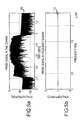
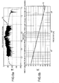
- One version of the first probe signal S is an all-pass sequence 100 was shown in Figure 5a .
- the magnitude spectrum 102 of an all-pass sequence APP is approximately constant (i.e, 0 dB) over all frequencies.
- This probe signal has a very narrow peak autocorrelation sequence 104 as shown in figures 5c and 5d .
- the narrowness of the peak is inversely proportional to the bandwidth over which the magnitude spectrum is constant.
- the autocorrelation sequence's zero-lag value is far above any non-zero lag values and does not repeat. How much depends on the length of the sequence.
- a sequence of 1,024 (2 10 ) samples will have a zero-lag value at least 30dB above any non-zero lag while a sequence of 65,536 (2 16 ) samples will have a zero-lag value at least 60dB above any non-zero lag values.
- the all-pass sequence is such that during the room response acquisition process the energy in the room will be building up for all frequencies at the same time. This allows for shorter probe length when compared in sweeping sinusoidal probes.
- all-pass excitation exercises loudspeakers doser to their nominal mode of operation. At the same time this probe allows for accurate full bandwidth measurement of loudspeaker/room responses allowing for a very quick overall measurement process.
- a probe length of 2 16 samples allows for a frequency resolution of 0.73 Hz.
- the second probe signal may be designed for noise shaping or attenuation in a particular target band that may partially or fully overlap the specified acoustic band of the first probe signal.
- the second probe signal is a pre-emphasised sequence characterized by a pre-emphasis function applied to a base-band sequence that provides an amplified magnitude spectrum over portion of the specified the acoustic band. Because the sequence has an amplified magnitude spectrum (> 0 dB) over a portion of the acoustic band it will exhibit an attenuated magnitude spectrum ( ⁇ 0 dB) over other portions of the acoustic band for energy conservation, hence is not suitable for use as the first or primary probe signal.
- One version of the second probe signal PeS as shown in figure 6a is a pre-emphasized sequence 110 in which the pre-emphasis function applied to the base-band sequence is inversely proportion, to frequency (c/ ⁇ d) where c is the speed of sound and d is the separation of the microphones over a low frequency region of the specified acoustic band.
- radial frequency ⁇ 2 ⁇ f where f is Hz.
- the two are represented by a constant scale factor, they are used interchangeably.
- the functional dependency on frequency may be omitted for simplicity.
- the magnitude spectrum 112 is inversely proportional to frequency. For frequencies less than 500 Hz, the magnitude spectrum is >0 dB.
- the amplification is clipped at 20 dB at the lowest frequencies.
- the use of the second probe signal to compute the room spectral measure at low frequencies has the advantage of attenuating low frequency noise in the case of a single microphone and of attenuating low frequency noise in the pressure component and improving the computation of the velocity component in the case of a multi-microphone array.
- the second pre-emphasized probe signal is generates from a base-band sequence, which may or may not be the broadband sequence of the first probe signal.
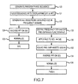
- An embodiment of a method for constructing an all-pass probe signal and a pre-emphasized probe signal is illustrated in figure 7 .
- the probe signals are preferably constructed in the frequency domain by generating a random number sequence between - ⁇ ,+ ⁇ having a length of a power of 2" (step 120 ).
- a random number sequence between - ⁇ ,+ ⁇ having a length of a power of 2"
- the MATLAB Mat rix Lab oratory
- rand "rand" function based on the Mersene Twister algorithm
- Smoothing filters are applied to the random number sequence (step 121 ).
- the random sequence is used as the phase ( ⁇ ) of a frequency response assuming an all-pass magnitude to generate the all-pass probe sequence S(1) in the frequency domain (step 122 ).
- the inverse FFT of S(f) is calculated (step 124 ) and normalized (step 126 ) to produce the first all-pass probe signal S(n) in the time domain where n is a sample index in time.
- the frequency dependent (c/ ⁇ d) pre-emphasis function Pe(t) is defined (step 128 ) and applied to the all-pass frequency domain signal S(f) to yield PeS(f) (step 130 ).
- PeP(f) may be bound or clipped at the lowest frequencies (step 132 ).
- the inverse FFT of PeS(f) is calculated (step 134 ), examined to ensure that there are no serious edge-effects and normalised to have high level while avoiding clipping (step 136) to produce the second pre-emphasized probe signal PeS(n) in the time domain.
- the probe signal(s) may be calculated offline and stored in memory.
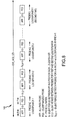
- the A/V preamplifier supplies the one or more probe signals, all-pass probe (APP) and pre-emphasized probe (PES) of duration (length)"P", to the audio outputs in accordance with a transmission schedule 140 so that each probe signal is transmitted as sound waves by a loudspeaker into the listening environment in non-overlapping time slots separates by silent periods.
- the preamplifier sends one probe signal to one loudspeaker at a time.
- the all-pass probe APP is sent first to a single loudspeaker and after a predetermined silent period the pre-emphasized probe signal PES is sent to the same loudspeaker.
- a silent period is inserted between the transmission of the 1 st and 2 nd probe signals to the same speaker.
- a silent period S 1,2 and S k,k+1 is inserted between the transmission of the 1 st and 2 nd probe signals between the 1 st and 2 nd loud speakers and the k th and k th +1 loudspeakers, respectively, to enable robust yet fast acquisition.
- the minimum duration of the silent period S is the maximum RIR length to be acquired.
- the minimum duration of the silent period S 1,2 is the sum of the maximum RIR length and the maximum assumed delay through the system.
- the minimum duration of the silent period S k,k+1 is imposed by the sum of (a) the maximum RIR length to be acquired, (b) twice the maximum assumed relative delay between the loudspeakers and (c) twice the room response processing block length. Silence between the probes to different loudspeakers may be increased if a processor is performing the acquisition processing or room response processing in the silent periods and requires more time to finish the calculations.
- the first channel is suitably probed twice, once at the beginning and once after all other loudspeakers to cheek for consistency in the delays.
- the total system acquisition length Sys_Acq_Len 2*P + S + S 1 , 2 + N_LoudSpkrs*(2*P + S + S k,k+1 ). Withe a probe length of 65,536 and dual-probe test of 6 loudspeakers the total acquisition time can be less than 31 seconds.
- the methodology for deconvolution of captured microphone signal based on very long FTTs is suitable for off-line processing scenarios.
- the pre-amplifier has enough memory to store the entire captured microphone signal and only after the capturing process is completed to start the estimation of the propagation delay and room response.
- the A/V preamplifier suitably performs the de-convolution and delay estimation in real-time while capturing the microphones signals.
- the methodology for real-time estimation of delays and room responses can be tailored for different system requirements in terms of trade-off between memory, MIPS and acquisition time requirements;
- each successive block of N/2 samples is processed to update the RIR.
- An N-point FFT is performed on each block for each microphone to output a frequency response of length Nx1 (step 150 ).
- the current FFT partition for each microphone signal (non-negative frequencies only) is stored in a vector of length (N/2+1) x 1 (step 152 ).
- These vectors are accumulated in a first-in first-out (FIFO) bases to create a matrix Input_FFT_Matrix of K FFT partitions of dimensions (N/2+1) x K (step 154 ).
- a set of partitioned FFTs (non-negative frequencies only) of a time reversed broadband probe signal of length K*N/2 samples are pre-calculated and stored as a matrix Filt_FFT of dimensions (N/2+1) x K (step 156 ).
- a fast convolution using an overlap and save method its performed on the Input_FFT_Matrix with the Filt_FFT matrix to provide an N/2+1 point candidate frequency response for the current block (step 158 ).
- the overlap and save method multiplies the value in each frequency bin of the Filt_FFT_matrix by the corresponding valve in the Input_FFT_Matrix and averages the values across the K columns of the matrix.
- an N/point inverse FFT is performed with conjugate symmetry extension for negative frequencies to obtain a new block of N/2x1 samples of a candidate room impulse response (RIR) (step 160 ).
- Successive blocks of candidate RIRs are appended and stored up to a specified RIR length (RIR_Length)(step 162 ).
- a new block of N/2x1 samples of the HE of the candidate room impulse response is obtained (step 164 ).
- the maximum (peak) of the HE over the incoming blocks of N/2 samples is tracked and updated to track a global peak over all blocks (step 166 ), M samples of the HE around its global peak are stored (step 168 ). If a new global peak is detected, a control signal is issued to flush the stored candidate RIR and restart.
- the DSP outputs the RIR, HE peak location and the M samples of the HE around its peak.
- the pre-emphasized probe signal is processed in the same manner to generate a candidate RIR that is stored up to RIR_Length (step 170 ),
- the location of the global peak of the HE for the all-pass probe signal is used to start accumulation of the candidate RIR.
- the DSP outputs the RIR for the pte-emphasized probe signal.
- the room responses are processed by a cochlear mechanics inspired time-frequency processing, where a longer part of room response is considered at lower frequencies and progress ⁇ vely shorter parts of room response are considered at higher and higher in frequencies.
- This variable resolution time-frequency processing may be performed either on the time-domain RIR or the frequency-domain spectral measure.
- the audio channel indicator nch is set to zero (step 200 ). If the SpeakerAvtivityMask[nch] is not true (i.e. no more loudspeakers coupled) (step 202 ) the loop processing terminates and skips to the final step of adjusting all correction filters tao a common target curve. Otherwise the process optionally applies variable resolution time-frequency processing to the RIR (step 204 ).
- a time varying filter is applies to the RIR. The time varying filter is constructed so that the beginning of the RIR is not filtered at all but as the filter progresses in time through the RIR a low pass filter is applied whose bandwidth becomes progressive smaller with time.
- the room responses four different microphones are realigned (step 206 ). In the case of a single microphone no realignment is required If the room responses are provide in the time domain as a RIR, they are realigned such that the relative delays between RIRs in each microphone are restored and a FFT is calculated to obtain aligned RFR. If the room responses are provided in the frequency domain as a RFR, realignment is achieved by a phase shift corresponding to the relative delay between microphone-signals.
- the frequency response for each frequency bin k for the all-pass probe signal is H k
- for the pre-emphasized probe signal is H k,pe where the functional dependency on frequency has been omitted.
- a spectral measure is constructed from the realigned RFRs for the current audio channel (step 208 ).
- the spectral measure may be calculated in any number of ways from the RFRs including but non limited to a magnitude spectrum and an energy measure.
- the spectral measure 210 may blend a spectral measure 212 calculated from the frequency response H k,pe for the pre-emphasized probe signal for frequencies below a cut-off frequency bin k t and a spectral measure 214 from the frequency response H k for the broadband probe signal for frequencies above the out-off frequency bin k t .
- the spectral measures are blended by appending the H k above the cut-off to the H k,pe below the cut-off.
- the different spectral measures may be combined has a weighted average in a transition region 216 around the cut-off frequency bin if desired.
- variable resolution time-Frequency processing may be applied to the room responses in step 204.
- variable resolution time-frequency processing may be applied to the spectral measure (step 220 ).
- a smoothing filter is applied to the spectral measure. The smoothing filter is constructed so that the amount of smoothing increases with frequency.
- the frequency correction filters can be calculated. To do so, the system is provided with a desired corrected frequency response or "target curve". This target curve is one of the main contributor to the characteristic sound of any room correction system.
- One approach is to use it single common target curve reflecting any user preferences for all audio channels.
- Another approach rejected in Figure 10 is to generate and save a unique channel target curve for each audio channel (step 222) and generate a common target curve for all channels (step 224 ).
- a room correction process should first of all achieve matching of the first arrival of sound (in time, amplitude and timbre) from each of the loudspeakers in the room.
- the room spectral measure Is smoothed with a very coarse low pass filter such that only the trend of the measure is preserved. In other words the trend of direct path of a loudspeaker response is preserved since all room contributions are excluded or smoothed out.
- These smoothed direct path loudspeaker responses are used as the channel target curves during the calculation of frequency correction filters for each loudspeaker separately (step 226 ). As a result only relatively small order correction filters are required since only peaks and dips around the target need to be corrected.
- the audio channel indicator nch is incremented by one (step 228) and tested against the total number of channels .NumCh to determine if all possible audio channels have been processed (step 230). If not, the entire process repeats for the next audio channel. If yes, the process proceeds to make final adjustments to the correction filters for the common target curve.
- the common target curve is generated as an average of the channel target curves over all loudspeakers. Any user preferences or user selectable target curves may be superimposed on the common target curve. Any adjustment to the correction filters are made to compensate for differences in the channel target curves and the common target curve (step 229) . Due to the relatively small variations between the per channel and common target curves and the highly smoothed curves, the requirements imposed by the common target curve can be implemented with very simple filters.
- the spectral measure computed in step 208 may constitute an energy measure.
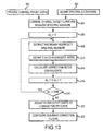
- An embodiment for computing energy measures for various combinations of a single microphone or a tetrahedral microphone and a single probe or a dual probe is illustrated in figure 12 .
- the analysis module determines whether there are 1 or 4 microphones (step 230) and then determines whether there is a single or dual-probe room response (step 232 for a single microphone and step 234 for a tetrahedral microphone). This embodiment is described for 4 microphones, more generally the method may be applied to any multi-microphone array.
- Energy measure E k corresponds to the sound pressure.
- the pre-emphasis function Pe c/ ⁇ d
- the de-emphasis function De ⁇ d/c.
- E k H k *conj(H k ) (step 248) .
- the effect of using the dual-probe is to attenuate low frequency noise in the energy measure.
- the analysis module computes a pressure gradient across the microphone array from which sound velocity components may be extracted.
- a pressure gradient across the microphone array from which sound velocity components may be extracted.
- a first part of the energy measure includes a sound pressure component and a sound velocity component (step 242) .
- the "average” may be computed as any variation of a weighted average.
- the application of frequency dependent weighting will have the effect of amplifying noise at low frequencies.
- the low frequency portion of the energy measure E K 0.5(P_E k + V_E k ) (step 248 ) although any variation of a weighted average may be used.
- 2 or the sum of the squares E K 0.25(
- a first part of the energy measure includes a sound pressure component and a sound velocity component (step 262 ).
- the "average” may "be computed as any variation of a weighted average.
- the use of the pre-emphasized probe signal removes the step of applying frequency dependent weighting.
- the low frequency portion of the energy measure E k 0.5(P_E k + V_E k ) (step 268) (or other weighted combination).
- 2 or the sum of the squares E K 0.25(
- the dual-probe, multi-microphone case combines both forming the energy measure from sound pressure and sound velocity components and using the pre-emphasized probe signal in order to avoid the frequency dependent sealing to extract the sound velocity components, hence provide a sound velocity that is more robust in the presence of noise.
- the spectral density of the acoustic energy density in the room is estimated.
- the ⁇ U ⁇ is indicating the l 2 norm of vector U.
- the sound velocity at location r( r x , y y , y z ) is related to the pressure using the linear Euler's equation.
- ⁇ P ( r,w ) is a Fourier transform of a pressure gradient along x, y and z coordinates at frequency w.
- a pressure gradient may be obtained from the assumption that the microphones are positioned such that the spatial variation in the pressure field is small over the volume occupied by the microphone array. This assumption places an upper hound on the frequency range at which this assumption may be used.
- RmES representative room energy spectrum
- RmES + 1 2 ⁇ R T R ⁇ 1 R T H 2 ⁇ H 1 H ⁇ H 1 H ⁇ H 1 H 3 ⁇ H 2 H 4 ⁇ H 2 H 4 ⁇ H 3 ⁇ 2
- RmES 1 2 ⁇ R T R ⁇ 1 R T H 2 ⁇ H 1 H 3 ⁇ H H 4 ⁇ H 1 H 3 ⁇ H 2 H 4 ⁇ H 2 H 4 ⁇ H 3 ⁇ 2
- 2 is very small.
- the noise in different microphones may be considered uncorrelated and consequently
- 2 This effectively reduces the desired signal to noise ratio and makes the pressure gradient noisy at low frequencies: Increasing the distance between the microphones will make the magnitude of desired signal ( H k - H l ) larger and consequently improve the effective SNR.
- this low frequency processing is applied in frequency region from 20Hz to around 500Hz. Its goal is to obtain an energy measure that is representative of a wide listening area in the room. At higher frequencies the goal is to characterize the direct path and few early reflections from the loudspeaker to the listening area. These characteristics mostly depend on loudspeaker construction and its position within the room and consequently do not vary much between different locations within the listening area. Therefore at high frequencies an energy measure based on a simple average (or more complex weighted average) of tetrahedral microphone signals is used, The resulting overall room energy measure is written as in Equation (12).
- Equation 8 corresponds to step 242 for computing the low-frequency component of E k.
- the 1 er term in equation 8 is the magnitude squared of the average frequency response (step 244 ) and the 2 nd term applies the frequency dependent weighting to the pressure gradient to estimate the velocity components and computes the magnitude squared (step 246 ).
- Equation 12 corresponds to steps 260 (low-frequency) and 270 (high-frequency).
- the 1 st term in equation 12 is the magnitude square of the de-emphasized average frequency response (step 264 ).
- the 2 nd term is the magnitude squared of the velocity components estimated from the pressure gradient.
- the sound velocity camponent of the low-frequency measure is computed directly from the measured room response H k or H k,ps , the steps of estimating the pressure gradient and obtaining the velocity components are integrally performed.
- minimum-phase FIR sub-band correction filters is based on AR model estimation for each band independently using the previously described room spectral (energy) measure.
- Each band can be constructed independently because the analysis/synthesis filter banks are non-eritically sampled.
- a channel target curve is provided (step 300 ).
- the channel target curve may be calculated by applying frequency smoothing to the room spectral measure, selecting a user defined target curve or by superimposing a user defined target curve onto the frequency smoothed room spectral measure.
- the room spectral measure may be bounded to prevent extreme requirements on the correction filters (step 302 ).
- the per channel mid-band gain may be estimated as an average of the room spectral measure over the mid-band frequency region. Excursions of the room spectrum measure are bonded between a maximum of the mid-band gain plus an upper bound (e,g. 20dB) and a minimum of the mid.
- the per channel target curve is combined with the bounded per channel room spectral measure to obtain an aggregate room spectral measure 303 (step 304 ). In each frequency bin, the room spectral measure is divided by the corresponding bin of the target curve to provide the aggregate room spectral measure.
- a sub-band counter sb is initialized to zero (step 306 ).
- Portions of the aggregate spectral measure are extracted that correspond to different sub-bands and remapped to base-band to mimic the downsampling of the analysis filter bank (step 308).
- the aggregate room spectral measure 303 is partitioned into overlapping frequency regions 310a, 310b and so forth corresponding to each band in the oversampled filter bank.
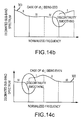
- Each partition is mapped to the base-band according to decimation rules that apply for even and odd filter bank bands as shown in figures 14c and 14b , respectively.
- the shapes of analysis filters are not included into the mapping. This is important because it is desirable to obtain correction filters that have as low order as possible. If the analysis filter bank filters are included the mapped spectrum will have steep falling edges. Hence the correction filters would require high order to unnecessarily correct for a shape of analysis filters.
- the partitions corresponding to the odd or even will have parts of the spectrum shifted but some other parts also flipped. This may result in spectral discontinuity that would require a high order frequency correction filter.
- the region of flipped spectrum is smoothed. This in return changes the fine detail of the spectrum in the smoothed region.
- the flipped sections are always in the region where synthesis filters already have high attenuation and consequently the contribution of this part of the partition to the final spectrum is negligible.
- An auto regressive (AR) model is estimated to the remapped aggregate room spectral measure (step 312 ).
- This autocorrelation sequence is used as the input to the Levinson-Durbin algorithm which computes an AR model, of desired order, that best matches the given energy spectrum in a least square sense.
- the denominator of this AR model (all-pole) filter is a minimum phase polynomial.
- the length of frequency correction filters in each sub-band are roughly determined by the length of room response, in the corresponding frequency region, that we have considered during the creation of overall room energy measure (length proportionally goes down as we move from low to high frequencies). However the final lengths can either be fine tuned empirically or automatically by use of AR order selection algorithms that observe the residual power and stop when a desired resolution is reached.
- the coefficients of the AR are mapped to coefficients of a minimum-phase all-zero sub-band correction filter (step 314 ).
- This FIR filter will perform frequency correction according to the inverse of the spectrum obtained by the AR model. To match filters between different bands all of the correction filters are suitably normalized.
- the sub-band counter sb is incremented (step 316 ) and compared to the number of sub-bands NSB (step 318 ) to repeat the process for the next audio channel or to terminate the per channel construction of the correction filters.
- the channel FIR filter coefficients may be adjusted to a common target curve (step 320 ).
- the adjusted filter coefficients are stored in system memory and used to configure the one or more processors to implement the P digital FIR sub-band correction filters for each audio channel shown in Figure 3 (step 322 ).
- the distance can be computed based on estimated propagation delay from the loudspeaker to the microphone array. Assuming that the sound wave propagating along the direct path between loudspeaker and microphone array can be approximated by a plane wave then the corresponding angle of arrival (AOA), elevation, with respect to an origin of a coordinate system defined by microphone array, can be estimated by observing the relationship between different microphone signals within the array. The loudspeaker azimuth and elevation are calculated from the estimated AOA.
- AOA angle of arrival
- an azimuth angle ⁇ and an elevation angle ⁇ are determined from an estimated angle of arrival (AOA) of a sound wave propagating from a loudspeaker to the tetrahedral microphone array.
- the algorithm for estimation of the AOA is based on a property of vector dot product to characterize the angle between two vectors.
- ⁇ s ⁇ c s
- r lk indicates vector connecting the microphone k to the microphone l
- T indicates matrix/array transpose operation
- s S x S y S z denotes a unary vector that is aligned with the direction of arrival of plane sound wave
- c indicates the speed of sound
- Fs indicates the sampling frequency
- t k indicates the time of arrival of a sound wave to the microphone k
- t l indicates the time of arrival of a sound wave to the microphone l.
- the achievable angular accuracy of AOA algorithms using the time delay estimates ultimately is limited by the accuracy of delay estimates and the separation between the microphone capsules. Smaller separation between the capsules implies smaller achievable accuracy.
- the separation between the microphone capsules is limited from the top by requirements of velocity estimation as well as aesthetics of the end product. Consequently the desired angular accuracy is achieved by adjusting the delay estimation accuracy. If the required delay estimation accuracy becomes a fraction of sampling interval, the analytic envelope of the room responses are interpolated around their corresponding peaks. New peak locations, with fraction of sample accuracy, represent new delay estimates used by the AOA algorithm.
Landscapes
- Physics & Mathematics (AREA)
- Engineering & Computer Science (AREA)
- Acoustics & Sound (AREA)
- Signal Processing (AREA)
- Stereophonic System (AREA)
- Circuit For Audible Band Transducer (AREA)
Applications Claiming Priority (2)
| Application Number | Priority Date | Filing Date | Title |
|---|---|---|---|
| US13/103,809 US9031268B2 (en) | 2011-05-09 | 2011-05-09 | Room characterization and correction for multi-channel audio |
| PCT/US2012/037081 WO2012154823A1 (en) | 2011-05-09 | 2012-05-09 | Room characterization and correction for multi-channel audio |
Publications (3)
| Publication Number | Publication Date |
|---|---|
| EP2708039A1 EP2708039A1 (en) | 2014-03-19 |
| EP2708039A4 EP2708039A4 (en) | 2015-06-17 |
| EP2708039B1 true EP2708039B1 (en) | 2016-08-10 |
Family
ID=47139621
Family Applications (1)
| Application Number | Title | Priority Date | Filing Date |
|---|---|---|---|
| EP12782597.4A Active EP2708039B1 (en) | 2011-05-09 | 2012-05-09 | Room characterization and correction for multi-channel audio |
Country Status (7)
| Country | Link |
|---|---|
| US (2) | US9031268B2 (enExample) |
| EP (1) | EP2708039B1 (enExample) |
| JP (1) | JP6023796B2 (enExample) |
| KR (1) | KR102036359B1 (enExample) |
| CN (1) | CN103621110B (enExample) |
| TW (3) | TWI700937B (enExample) |
| WO (1) | WO2012154823A1 (enExample) |
Cited By (1)
| Publication number | Priority date | Publication date | Assignee | Title |
|---|---|---|---|---|
| CN107864444A (zh) * | 2017-11-01 | 2018-03-30 | 大连理工大学 | 一种麦克风阵列频响校准方法 |
Families Citing this family (182)
| Publication number | Priority date | Publication date | Assignee | Title |
|---|---|---|---|---|
| US11431312B2 (en) | 2004-08-10 | 2022-08-30 | Bongiovi Acoustics Llc | System and method for digital signal processing |
| US10848867B2 (en) | 2006-02-07 | 2020-11-24 | Bongiovi Acoustics Llc | System and method for digital signal processing |
| US11202161B2 (en) | 2006-02-07 | 2021-12-14 | Bongiovi Acoustics Llc | System, method, and apparatus for generating and digitally processing a head related audio transfer function |
| US8385557B2 (en) * | 2008-06-19 | 2013-02-26 | Microsoft Corporation | Multichannel acoustic echo reduction |
| US8759661B2 (en) | 2010-08-31 | 2014-06-24 | Sonivox, L.P. | System and method for audio synthesizer utilizing frequency aperture arrays |
| US9549251B2 (en) * | 2011-03-25 | 2017-01-17 | Invensense, Inc. | Distributed automatic level control for a microphone array |
| US9094771B2 (en) * | 2011-04-18 | 2015-07-28 | Dolby Laboratories Licensing Corporation | Method and system for upmixing audio to generate 3D audio |
| US8653354B1 (en) * | 2011-08-02 | 2014-02-18 | Sonivoz, L.P. | Audio synthesizing systems and methods |
| JP6051505B2 (ja) * | 2011-10-07 | 2016-12-27 | ソニー株式会社 | 音声処理装置および音声処理方法、記録媒体、並びにプログラム |
| US20130166052A1 (en) * | 2011-12-27 | 2013-06-27 | Vamshi Kadiyala | Techniques for improving playback of an audio stream |
| US9084058B2 (en) | 2011-12-29 | 2015-07-14 | Sonos, Inc. | Sound field calibration using listener localization |
| US9690271B2 (en) | 2012-06-28 | 2017-06-27 | Sonos, Inc. | Speaker calibration |
| US9706323B2 (en) | 2014-09-09 | 2017-07-11 | Sonos, Inc. | Playback device calibration |
| US9106192B2 (en) | 2012-06-28 | 2015-08-11 | Sonos, Inc. | System and method for device playback calibration |
| US9219460B2 (en) | 2014-03-17 | 2015-12-22 | Sonos, Inc. | Audio settings based on environment |
| US9690539B2 (en) | 2012-06-28 | 2017-06-27 | Sonos, Inc. | Speaker calibration user interface |
| US9668049B2 (en) | 2012-06-28 | 2017-05-30 | Sonos, Inc. | Playback device calibration user interfaces |
| US9615171B1 (en) * | 2012-07-02 | 2017-04-04 | Amazon Technologies, Inc. | Transformation inversion to reduce the effect of room acoustics |
| TWI498014B (zh) * | 2012-07-11 | 2015-08-21 | Univ Nat Cheng Kung | 建立最佳化揚聲器聲場之方法 |
| US10175335B1 (en) * | 2012-09-26 | 2019-01-08 | Foundation For Research And Technology-Hellas (Forth) | Direction of arrival (DOA) estimation apparatuses, methods, and systems |
| US9699586B2 (en) * | 2012-10-02 | 2017-07-04 | Nokia Technologies Oy | Configuring a sound system |
| CN104956689B (zh) | 2012-11-30 | 2017-07-04 | Dts(英属维尔京群岛)有限公司 | 用于个性化音频虚拟化的方法和装置 |
| US9036825B2 (en) * | 2012-12-11 | 2015-05-19 | Amx Llc | Audio signal correction and calibration for a room environment |
| US9137619B2 (en) * | 2012-12-11 | 2015-09-15 | Amx Llc | Audio signal correction and calibration for a room environment |
| US9344828B2 (en) * | 2012-12-21 | 2016-05-17 | Bongiovi Acoustics Llc. | System and method for digital signal processing |
| CN103064061B (zh) * | 2013-01-05 | 2014-06-11 | 河北工业大学 | 三维空间声源定位方法 |
| JP6271586B2 (ja) * | 2013-01-16 | 2018-01-31 | ドルビー・インターナショナル・アーベー | Hoaラウドネスレベルを測定する方法及びhoaラウドネスレベルを測定する装置 |
| EP2949133B1 (en) * | 2013-01-24 | 2019-02-13 | Dolby Laboratories Licensing Corporation | Automatic loudspeaker polarity detection |
| WO2014164361A1 (en) | 2013-03-13 | 2014-10-09 | Dts Llc | System and methods for processing stereo audio content |
| CN105144754B (zh) | 2013-03-14 | 2017-03-15 | 苹果公司 | 扬声器与调节由房间中的扬声器发出的声音的方法和设备 |
| US9961472B2 (en) * | 2013-03-14 | 2018-05-01 | Apple Inc. | Acoustic beacon for broadcasting the orientation of a device |
| US10827292B2 (en) | 2013-03-15 | 2020-11-03 | Jawb Acquisition Llc | Spatial audio aggregation for multiple sources of spatial audio |
| JP6114587B2 (ja) * | 2013-03-19 | 2017-04-12 | 株式会社東芝 | 音響装置、記憶媒体、音響補正方法 |
| TWI508576B (zh) * | 2013-05-15 | 2015-11-11 | Lite On Opto Technology Changzhou Co Ltd | 揚聲器異音檢測方法及裝置 |
| EP2997327B1 (en) * | 2013-05-16 | 2016-12-07 | Koninklijke Philips N.V. | Apparatus and method for determining a room dimension estimate |
| TW201445983A (zh) * | 2013-05-28 | 2014-12-01 | Aim Inc | 播放系統之訊號輸入源自動選擇方法 |
| US9883318B2 (en) | 2013-06-12 | 2018-01-30 | Bongiovi Acoustics Llc | System and method for stereo field enhancement in two-channel audio systems |
| CN105473988B (zh) * | 2013-06-21 | 2018-11-06 | 布鲁尔及凯尔声音及振动测量公司 | 确定机动车辆的噪声源的噪声声音贡献的方法 |
| WO2015009748A1 (en) * | 2013-07-15 | 2015-01-22 | Dts, Inc. | Spatial calibration of surround sound systems including listener position estimation |
| WO2015009350A1 (en) * | 2013-07-16 | 2015-01-22 | Leeo, Inc. | Electronic device with environmental monitoring |
| US9116137B1 (en) | 2014-07-15 | 2015-08-25 | Leeo, Inc. | Selective electrical coupling based on environmental conditions |
| EP2830332A3 (en) | 2013-07-22 | 2015-03-11 | Fraunhofer-Gesellschaft zur Förderung der angewandten Forschung e.V. | Method, signal processing unit, and computer program for mapping a plurality of input channels of an input channel configuration to output channels of an output channel configuration |
| AU2014331094A1 (en) * | 2013-10-02 | 2016-05-19 | Stormingswiss Gmbh | Method and apparatus for downmixing a multichannel signal and for upmixing a downmix signal |
| US9906858B2 (en) | 2013-10-22 | 2018-02-27 | Bongiovi Acoustics Llc | System and method for digital signal processing |
| CN104681034A (zh) * | 2013-11-27 | 2015-06-03 | 杜比实验室特许公司 | 音频信号处理 |
| WO2015105788A1 (en) | 2014-01-10 | 2015-07-16 | Dolby Laboratories Licensing Corporation | Calibration of virtual height speakers using programmable portable devices |
| US9264839B2 (en) | 2014-03-17 | 2016-02-16 | Sonos, Inc. | Playback device configuration based on proximity detection |
| JP6439261B2 (ja) | 2014-03-19 | 2018-12-19 | ヤマハ株式会社 | オーディオ信号処理装置 |
| EP2925024A1 (en) * | 2014-03-26 | 2015-09-30 | Fraunhofer-Gesellschaft zur Förderung der angewandten Forschung e.V. | Apparatus and method for audio rendering employing a geometric distance definition |
| EP2963646A1 (en) | 2014-07-01 | 2016-01-06 | Fraunhofer-Gesellschaft zur Förderung der angewandten Forschung e.V. | Decoder and method for decoding an audio signal, encoder and method for encoding an audio signal |
| US9372477B2 (en) | 2014-07-15 | 2016-06-21 | Leeo, Inc. | Selective electrical coupling based on environmental conditions |
| AU2014204540B1 (en) * | 2014-07-21 | 2015-08-20 | Matthew Brown | Audio Signal Processing Methods and Systems |
| US9092060B1 (en) | 2014-08-27 | 2015-07-28 | Leeo, Inc. | Intuitive thermal user interface |
| US10078865B2 (en) | 2014-09-08 | 2018-09-18 | Leeo, Inc. | Sensor-data sub-contracting during environmental monitoring |
| US9952825B2 (en) | 2014-09-09 | 2018-04-24 | Sonos, Inc. | Audio processing algorithms |
| US9891881B2 (en) | 2014-09-09 | 2018-02-13 | Sonos, Inc. | Audio processing algorithm database |
| US9910634B2 (en) | 2014-09-09 | 2018-03-06 | Sonos, Inc. | Microphone calibration |
| US10127006B2 (en) | 2014-09-09 | 2018-11-13 | Sonos, Inc. | Facilitating calibration of an audio playback device |
| EP3192282A1 (en) * | 2014-09-12 | 2017-07-19 | Dolby Laboratories Licensing Corp. | Rendering audio objects in a reproduction environment that includes surround and/or height speakers |
| TWI628454B (zh) | 2014-09-30 | 2018-07-01 | 財團法人工業技術研究院 | 基於聲波的空間狀態偵測裝置、系統與方法 |
| KR102197230B1 (ko) * | 2014-10-06 | 2020-12-31 | 한국전자통신연구원 | 음향 특성을 예측하는 오디오 시스템 및 방법 |
| US9445451B2 (en) | 2014-10-20 | 2016-09-13 | Leeo, Inc. | Communicating arbitrary attributes using a predefined characteristic |
| US10026304B2 (en) | 2014-10-20 | 2018-07-17 | Leeo, Inc. | Calibrating an environmental monitoring device |
| EP3259927A1 (en) * | 2015-02-19 | 2017-12-27 | Dolby Laboratories Licensing Corporation | Loudspeaker-room equalization with perceptual correction of spectral dips |
| US10664224B2 (en) | 2015-04-24 | 2020-05-26 | Sonos, Inc. | Speaker calibration user interface |
| WO2016172593A1 (en) | 2015-04-24 | 2016-10-27 | Sonos, Inc. | Playback device calibration user interfaces |
| KR102051436B1 (ko) * | 2015-04-30 | 2019-12-03 | 후아웨이 테크놀러지 컴퍼니 리미티드 | 오디오 신호 처리 장치들 및 방법들 |
| EP3292703B8 (en) * | 2015-05-15 | 2021-03-10 | Nureva Inc. | System and method for embedding additional information in a sound mask noise signal |
| JP6519336B2 (ja) * | 2015-06-16 | 2019-05-29 | ヤマハ株式会社 | オーディオ機器および同期再生方法 |
| KR102340202B1 (ko) | 2015-06-25 | 2021-12-17 | 한국전자통신연구원 | 실내의 반사 특성을 추출하는 오디오 시스템 및 방법 |
| KR102393798B1 (ko) | 2015-07-17 | 2022-05-04 | 삼성전자주식회사 | 오디오 신호 처리 방법 및 장치 |
| US9538305B2 (en) | 2015-07-28 | 2017-01-03 | Sonos, Inc. | Calibration error conditions |
| US10091581B2 (en) * | 2015-07-30 | 2018-10-02 | Roku, Inc. | Audio preferences for media content players |
| US9693165B2 (en) | 2015-09-17 | 2017-06-27 | Sonos, Inc. | Validation of audio calibration using multi-dimensional motion check |
| EP3531714B1 (en) | 2015-09-17 | 2022-02-23 | Sonos Inc. | Facilitating calibration of an audio playback device |
| US9607603B1 (en) * | 2015-09-30 | 2017-03-28 | Cirrus Logic, Inc. | Adaptive block matrix using pre-whitening for adaptive beam forming |
| US9877137B2 (en) | 2015-10-06 | 2018-01-23 | Disney Enterprises, Inc. | Systems and methods for playing a venue-specific object-based audio |
| CN108432270B (zh) * | 2015-10-08 | 2021-03-16 | 班安欧股份公司 | 扬声器系统中的主动式房间补偿 |
| US9838783B2 (en) * | 2015-10-22 | 2017-12-05 | Cirrus Logic, Inc. | Adaptive phase-distortionless magnitude response equalization (MRE) for beamforming applications |
| US10708701B2 (en) * | 2015-10-28 | 2020-07-07 | Music Tribe Global Brands Ltd. | Sound level estimation |
| CN105407443B (zh) * | 2015-10-29 | 2018-02-13 | 小米科技有限责任公司 | 录音方法及装置 |
| US9801013B2 (en) | 2015-11-06 | 2017-10-24 | Leeo, Inc. | Electronic-device association based on location duration |
| US10805775B2 (en) | 2015-11-06 | 2020-10-13 | Jon Castor | Electronic-device detection and activity association |
| US9589574B1 (en) | 2015-11-13 | 2017-03-07 | Doppler Labs, Inc. | Annoyance noise suppression |
| CN108370457B (zh) | 2015-11-13 | 2021-05-28 | 杜比实验室特许公司 | 个人音频系统、声音处理系统及相关方法 |
| US10045144B2 (en) | 2015-12-09 | 2018-08-07 | Microsoft Technology Licensing, Llc | Redirecting audio output |
| US10293259B2 (en) | 2015-12-09 | 2019-05-21 | Microsoft Technology Licensing, Llc | Control of audio effects using volumetric data |
| US9743207B1 (en) | 2016-01-18 | 2017-08-22 | Sonos, Inc. | Calibration using multiple recording devices |
| US10003899B2 (en) | 2016-01-25 | 2018-06-19 | Sonos, Inc. | Calibration with particular locations |
| US11106423B2 (en) | 2016-01-25 | 2021-08-31 | Sonos, Inc. | Evaluating calibration of a playback device |
| WO2017165837A1 (en) * | 2016-03-24 | 2017-09-28 | Dolby Laboratories Licensing Corporation | Near-field rendering of immersive audio content in portable computers and devices |
| US9991862B2 (en) * | 2016-03-31 | 2018-06-05 | Bose Corporation | Audio system equalizing |
| US9860662B2 (en) | 2016-04-01 | 2018-01-02 | Sonos, Inc. | Updating playback device configuration information based on calibration data |
| US9864574B2 (en) | 2016-04-01 | 2018-01-09 | Sonos, Inc. | Playback device calibration based on representation spectral characteristics |
| US9763018B1 (en) * | 2016-04-12 | 2017-09-12 | Sonos, Inc. | Calibration of audio playback devices |
| CN107370695B (zh) * | 2016-05-11 | 2023-10-03 | 浙江诺尔康神经电子科技股份有限公司 | 基于延时抑制的人工耳蜗射频探测方法和系统 |
| JP2017216614A (ja) * | 2016-06-01 | 2017-12-07 | ヤマハ株式会社 | 信号処理装置および信号処理方法 |
| US9860670B1 (en) | 2016-07-15 | 2018-01-02 | Sonos, Inc. | Spectral correction using spatial calibration |
| US9794710B1 (en) | 2016-07-15 | 2017-10-17 | Sonos, Inc. | Spatial audio correction |
| US10372406B2 (en) | 2016-07-22 | 2019-08-06 | Sonos, Inc. | Calibration interface |
| US10459684B2 (en) | 2016-08-05 | 2019-10-29 | Sonos, Inc. | Calibration of a playback device based on an estimated frequency response |
| EP3519846B1 (en) * | 2016-09-29 | 2023-03-22 | Dolby Laboratories Licensing Corporation | Automatic discovery and localization of speaker locations in surround sound systems |
| US10375498B2 (en) * | 2016-11-16 | 2019-08-06 | Dts, Inc. | Graphical user interface for calibrating a surround sound system |
| FR3065136B1 (fr) | 2017-04-10 | 2024-03-22 | Pascal Luquet | Procede et systeme d'acquisition sans fil de reponse impulsionnelle par methode de sinus glissant |
| EP3402220A1 (en) * | 2017-05-11 | 2018-11-14 | Tap Sound System | Obtention of latency information in a wireless audio system |
| US10764682B2 (en) * | 2017-05-17 | 2020-09-01 | Panasonic Intellectual Property Management Co., Ltd. | Playback system, control device, control method, and program |
| US11197119B1 (en) | 2017-05-31 | 2021-12-07 | Apple Inc. | Acoustically effective room volume |
| CN107484069B (zh) * | 2017-06-30 | 2019-09-17 | 歌尔智能科技有限公司 | 扬声器所处位置的确定方法及装置、扬声器 |
| US11375390B2 (en) * | 2017-07-21 | 2022-06-28 | Htc Corporation | Device and method of handling a measurement configuration and a reporting |
| US10341794B2 (en) | 2017-07-24 | 2019-07-02 | Bose Corporation | Acoustical method for detecting speaker movement |
| US10231046B1 (en) | 2017-08-18 | 2019-03-12 | Facebook Technologies, Llc | Cartilage conduction audio system for eyewear devices |
| CN109753847B (zh) * | 2017-11-02 | 2021-03-30 | 华为技术有限公司 | 一种数据的处理方法以及ar设备 |
| US10748533B2 (en) | 2017-11-08 | 2020-08-18 | Harman International Industries, Incorporated | Proximity aware voice agent |
| US10458840B2 (en) * | 2017-11-08 | 2019-10-29 | Harman International Industries, Incorporated | Location classification for intelligent personal assistant |
| EP3518562A1 (en) | 2018-01-29 | 2019-07-31 | Fraunhofer-Gesellschaft zur Förderung der angewandten Forschung e.V. | Audio signal processor, system and methods distributing an ambient signal to a plurality of ambient signal channels |
| US10523171B2 (en) | 2018-02-06 | 2019-12-31 | Sony Interactive Entertainment Inc. | Method for dynamic sound equalization |
| US10186247B1 (en) * | 2018-03-13 | 2019-01-22 | The Nielsen Company (Us), Llc | Methods and apparatus to extract a pitch-independent timbre attribute from a media signal |
| JP2021521700A (ja) | 2018-04-11 | 2021-08-26 | ボンジョビ アコースティックス リミテッド ライアビリティー カンパニー | オーディオ強化聴力保護システム |
| EP3557887B1 (en) * | 2018-04-12 | 2021-03-03 | Dolby Laboratories Licensing Corporation | Self-calibrating multiple low-frequency speaker system |
| GB2573537A (en) | 2018-05-09 | 2019-11-13 | Nokia Technologies Oy | An apparatus, method and computer program for audio signal processing |
| WO2019217808A1 (en) * | 2018-05-11 | 2019-11-14 | Dts, Inc. | Determining sound locations in multi-channel audio |
| KR102573148B1 (ko) * | 2018-05-28 | 2023-08-30 | 비.지. 네게브 테크놀로지즈 앤드 애플리케이션스 리미티드, 엣 벤-구리온 유니버시티 | 사운드 교정을 위한 2-채널 공간 전달 함수의 지각적으로-투명한 추정 |
| WO2020028833A1 (en) | 2018-08-02 | 2020-02-06 | Bongiovi Acoustics Llc | System, method, and apparatus for generating and digitally processing a head related audio transfer function |
| CN109166592B (zh) * | 2018-08-08 | 2023-04-18 | 西北工业大学 | 基于生理参数的hrtf分频段线性回归方法 |
| JP2020036113A (ja) * | 2018-08-28 | 2020-03-05 | シャープ株式会社 | 音響システム |
| US11206484B2 (en) | 2018-08-28 | 2021-12-21 | Sonos, Inc. | Passive speaker authentication |
| US10299061B1 (en) | 2018-08-28 | 2019-05-21 | Sonos, Inc. | Playback device calibration |
| FR3085572A1 (fr) * | 2018-08-29 | 2020-03-06 | Orange | Procede pour une restitution sonore spatialisee d'un champ sonore audible en une position d'un auditeur se deplacant et systeme mettant en oeuvre un tel procede |
| CN112602335A (zh) * | 2018-08-31 | 2021-04-02 | 哈曼国际工业有限公司 | 音质增强和个性化 |
| GB2577905A (en) * | 2018-10-10 | 2020-04-15 | Nokia Technologies Oy | Processing audio signals |
| US11961522B2 (en) * | 2018-11-28 | 2024-04-16 | Samsung Electronics Co., Ltd. | Voice recognition device and method |
| WO2020150598A1 (en) * | 2019-01-18 | 2020-07-23 | University Of Washington | Systems, apparatuses. and methods for acoustic motion tracking |
| WO2020153736A1 (en) | 2019-01-23 | 2020-07-30 | Samsung Electronics Co., Ltd. | Method and device for speech recognition |
| CN111698629B (zh) * | 2019-03-15 | 2021-10-15 | 北京小鸟听听科技有限公司 | 音频重放设备的校准方法、装置及计算机存储介质 |
| EP3755009B1 (en) * | 2019-06-19 | 2025-02-05 | Google LLC | Method and bluetooth device for calibrating multimedia devices |
| WO2021021752A1 (en) | 2019-07-30 | 2021-02-04 | Dolby Laboratories Licensing Corporation | Coordination of audio devices |
| US11968268B2 (en) | 2019-07-30 | 2024-04-23 | Dolby Laboratories Licensing Corporation | Coordination of audio devices |
| CN114208209B (zh) | 2019-07-30 | 2023-10-31 | 杜比实验室特许公司 | 音频处理系统、方法和介质 |
| JP7578219B2 (ja) | 2019-07-30 | 2024-11-06 | ドルビー ラボラトリーズ ライセンシング コーポレイション | 複数のスピーカーを通じた複数のオーディオ・ストリームの再生の管理 |
| US10734965B1 (en) | 2019-08-12 | 2020-08-04 | Sonos, Inc. | Audio calibration of a portable playback device |
| FI131802B1 (en) | 2019-09-02 | 2025-12-05 | Genelec Oy | System and method for producing complementary sound |
| CN112530450B (zh) | 2019-09-17 | 2025-04-11 | 杜比实验室特许公司 | 频域中的样本精度延迟识别 |
| TWI725567B (zh) * | 2019-10-04 | 2021-04-21 | 友達光電股份有限公司 | 揚聲系統、顯示裝置以及音場重建方法 |
| US11432069B2 (en) | 2019-10-10 | 2022-08-30 | Boomcloud 360, Inc. | Spectrally orthogonal audio component processing |
| WO2021127286A1 (en) | 2019-12-18 | 2021-06-24 | Dolby Laboratories Licensing Corporation | Audio device auto-location |
| FR3106030B1 (fr) * | 2020-01-06 | 2022-05-20 | Innovation Electro Acoustique | Procédé et dispositif associé pour transformer des caractéristiques d’un signal audio |
| CN113552938B (zh) | 2020-04-26 | 2024-11-15 | 京东方科技集团股份有限公司 | 基于物联网的动作关联方法、电子设备和存储介质 |
| US11170752B1 (en) * | 2020-04-29 | 2021-11-09 | Gulfstream Aerospace Corporation | Phased array speaker and microphone system for cockpit communication |
| KR20210142393A (ko) * | 2020-05-18 | 2021-11-25 | 엘지전자 주식회사 | 영상표시장치 및 그의 동작방법 |
| CN111526455A (zh) * | 2020-05-21 | 2020-08-11 | 菁音电子科技(上海)有限公司 | 车载音响的校正增强方法及系统 |
| CN111551180B (zh) * | 2020-05-22 | 2022-08-26 | 桂林电子科技大学 | 一种可辨识los/nlos声信号的智能手机室内定位系统和方法 |
| JP7552089B2 (ja) * | 2020-06-18 | 2024-09-18 | ヤマハ株式会社 | 音響特性の補正方法および音響特性補正装置 |
| CN111818223A (zh) * | 2020-06-24 | 2020-10-23 | 瑞声科技(新加坡)有限公司 | 声音外放的模式切换方法、装置、设备、介质及发声系统 |
| CN113963712B (zh) * | 2020-07-21 | 2025-07-25 | 华为技术有限公司 | 滤除回声的方法、电子设备和计算机可读存储介质 |
| US11678111B1 (en) * | 2020-07-22 | 2023-06-13 | Apple Inc. | Deep-learning based beam forming synthesis for spatial audio |
| US11830471B1 (en) * | 2020-08-31 | 2023-11-28 | Amazon Technologies, Inc. | Surface augmented ray-based acoustic modeling |
| KR102484145B1 (ko) * | 2020-10-29 | 2023-01-04 | 한림대학교 산학협력단 | 소리방향성 분별능 훈련시스템 및 방법 |
| EP4256814B1 (en) | 2020-12-03 | 2025-01-29 | Dolby Laboratories Licensing Corporation | Insertion of forced gaps for pervasive listening |
| KR20230113314A (ko) | 2020-12-03 | 2023-07-28 | 돌비 레버러토리즈 라이쎈싱 코오포레이션 | 오디오 디바이스의 자동 정위 |
| US12395809B2 (en) | 2020-12-03 | 2025-08-19 | Dolby Laboratories Licensing Corporation | Audibility at user location through mutual device audibility |
| EP4243015A4 (en) * | 2021-01-27 | 2024-04-17 | Samsung Electronics Co., Ltd. | AUDIO PROCESSING APPARATUS AND METHOD |
| JP7808611B2 (ja) | 2021-02-05 | 2026-01-29 | アルコン インコーポレイティド | 音声制御式外科用システム |
| US11553298B2 (en) | 2021-02-08 | 2023-01-10 | Samsung Electronics Co., Ltd. | Automatic loudspeaker room equalization based on sound field estimation with artificial intelligence models |
| US20220329960A1 (en) * | 2021-04-13 | 2022-10-13 | Microsoft Technology Licensing, Llc | Audio capture using room impulse responses |
| WO2022232682A1 (en) * | 2021-04-30 | 2022-11-03 | That Corporation | Passive sub-audible room path learning with noise modeling |
| US11792594B2 (en) * | 2021-07-29 | 2023-10-17 | Samsung Electronics Co., Ltd. | Simultaneous deconvolution of loudspeaker-room impulse responses with linearly-optimal techniques |
| WO2023056258A1 (en) | 2021-09-30 | 2023-04-06 | Sonos, Inc. | Conflict management for wake-word detection processes |
| CN116070000B (zh) * | 2021-11-01 | 2025-11-21 | 华为终端有限公司 | 用于确定方位信息的方法和电子设备 |
| KR102743818B1 (ko) * | 2021-11-09 | 2024-12-18 | 한림대학교 산학협력단 | 소리방향성 분별능 검사시스템 및 검사방법 |
| CA3237444A1 (en) * | 2021-11-09 | 2023-05-19 | Andreas Silzle | Early reflection concept for auralization |
| CN114286278B (zh) * | 2021-12-27 | 2024-03-15 | 北京百度网讯科技有限公司 | 音频数据处理方法、装置、电子设备及存储介质 |
| US11653164B1 (en) * | 2021-12-28 | 2023-05-16 | Samsung Electronics Co., Ltd. | Automatic delay settings for loudspeakers |
| WO2023131399A1 (en) * | 2022-01-04 | 2023-07-13 | Fraunhofer-Gesellschaft zur Förderung der angewandten Forschung e.V. | Apparatus and method for multi device audio object rendering |
| US12267664B2 (en) * | 2022-01-10 | 2025-04-01 | Sound United Llc | Virtual and mixed reality audio system environment correction |
| US12323780B2 (en) * | 2022-04-28 | 2025-06-03 | Samsung Electronics Co., Ltd. | Bayesian optimization for simultaneous deconvolution of room impulse responses |
| US20230388737A1 (en) * | 2022-05-27 | 2023-11-30 | Shure Acquisition Holdings, Inc. | Inferring characteristics of physical enclosures using a plurality of audio signals |
| KR102649882B1 (ko) * | 2022-05-30 | 2024-03-22 | 엘지전자 주식회사 | 사운드 시스템 및 음향 최적화를 위한 그 사운드 시스템의 제어 방법 |
| EP4329337A1 (en) | 2022-08-22 | 2024-02-28 | Bang & Olufsen A/S | Method and system for surround sound setup using microphone and speaker localization |
| US12279098B2 (en) * | 2022-12-28 | 2025-04-15 | Spotify Ab | Systems, methods and computer program products for selecting audio filters |
| CN118136042B (zh) * | 2024-05-10 | 2024-07-23 | 四川湖山电器股份有限公司 | 基于iir频谱拟合的频谱优化方法、系统、终端及介质 |
| CN119233160A (zh) * | 2024-09-26 | 2024-12-31 | 南京乐韵瑞信息技术有限公司 | 智能音箱系统的延迟自动校准方法、装置、设备及存储介质 |
| CN119071684B (zh) * | 2024-11-05 | 2025-01-28 | 瑞声光电科技(常州)有限公司 | 一种音频控制方法、装置、车载音响系统 |
Family Cites Families (32)
| Publication number | Priority date | Publication date | Assignee | Title |
|---|---|---|---|---|
| GB9026906D0 (en) * | 1990-12-11 | 1991-01-30 | B & W Loudspeakers | Compensating filters |
| JPH04295727A (ja) * | 1991-03-25 | 1992-10-20 | Sony Corp | インパルス応答測定方法 |
| US5757927A (en) | 1992-03-02 | 1998-05-26 | Trifield Productions Ltd. | Surround sound apparatus |
| JP3191512B2 (ja) * | 1993-07-22 | 2001-07-23 | ヤマハ株式会社 | 音響特性補正装置 |
| US6760451B1 (en) | 1993-08-03 | 2004-07-06 | Peter Graham Craven | Compensating filters |
| JPH08182100A (ja) * | 1994-10-28 | 1996-07-12 | Matsushita Electric Ind Co Ltd | 音像定位方法および音像定位装置 |
| JP2870440B2 (ja) * | 1995-02-14 | 1999-03-17 | 日本電気株式会社 | 立体音場再生方式 |
| GB9911737D0 (en) | 1999-05-21 | 1999-07-21 | Philips Electronics Nv | Audio signal time scale modification |
| JP2000354300A (ja) * | 1999-06-11 | 2000-12-19 | Accuphase Laboratory Inc | マルチチャンネルオーディオ再生装置 |
| JP2001025085A (ja) * | 1999-07-08 | 2001-01-26 | Toshiba Corp | チャネル配置装置 |
| US7158643B2 (en) | 2000-04-21 | 2007-01-02 | Keyhold Engineering, Inc. | Auto-calibrating surround system |
| IL141822A (en) | 2001-03-05 | 2007-02-11 | Haim Levy | A method and system for imitating a 3D audio environment |
| AU2003232175A1 (en) * | 2002-06-12 | 2003-12-31 | Equtech Aps | Method of digital equalisation of a sound from loudspeakers in rooms and use of the method |
| FR2850183B1 (fr) | 2003-01-20 | 2005-06-24 | Remy Henri Denis Bruno | Procede et dispositif de pilotage d'un ensemble de restitution a partir d'un signal multicanal. |
| JP2005072676A (ja) | 2003-08-27 | 2005-03-17 | Pioneer Electronic Corp | 自動音場補正装置及びそのためのコンピュータプログラム |
| JP4568536B2 (ja) * | 2004-03-17 | 2010-10-27 | ソニー株式会社 | 測定装置、測定方法、プログラム |
| US7630501B2 (en) | 2004-05-14 | 2009-12-08 | Microsoft Corporation | System and method for calibration of an acoustic system |
| WO2006004099A1 (ja) | 2004-07-05 | 2006-01-12 | Pioneer Corporation | 残響調整装置、残響補正方法、および、音響再生システム |
| JP2006031875A (ja) | 2004-07-20 | 2006-02-02 | Fujitsu Ltd | 記録媒体基板および記録媒体 |
| JP4705349B2 (ja) | 2004-08-20 | 2011-06-22 | 株式会社タムラ製作所 | ワイヤレスマイクシステム、音声伝送再生方法、ワイヤレスマイク送信機、音声送信方法及びプログラム |
| EP1638083B1 (en) * | 2004-09-17 | 2009-04-22 | Harman Becker Automotive Systems GmbH | Bandwidth extension of bandlimited audio signals |
| US7826624B2 (en) | 2004-10-15 | 2010-11-02 | Lifesize Communications, Inc. | Speakerphone self calibration and beam forming |
| KR100636213B1 (ko) * | 2004-12-28 | 2006-10-19 | 삼성전자주식회사 | 실시간 주파수 특성 보정 방법 및 그를 적용한 사운드재생 장치 |
| TWI458365B (zh) * | 2005-04-12 | 2014-10-21 | Dolby Int Ab | 用以產生電平參數之裝置及方法、用以產生多聲道表示之裝置及方法以及儲存參數表示之儲存媒體 |
| EP1722360B1 (en) * | 2005-05-13 | 2014-03-19 | Harman Becker Automotive Systems GmbH | Audio enhancement system and method |
| JP4435232B2 (ja) | 2005-07-11 | 2010-03-17 | パイオニア株式会社 | オーディオシステム |
| CN101053152B (zh) * | 2005-07-29 | 2010-12-29 | 哈曼国际工业有限公司 | 自动音频调谐系统及方法 |
| US20070121955A1 (en) | 2005-11-30 | 2007-05-31 | Microsoft Corporation | Room acoustics correction device |
| JP4950220B2 (ja) | 2006-01-03 | 2012-06-13 | エスエル オーディオ エイ/エス | 部屋の中のスピーカーを等化する方法とシステム |
| EP1986466B1 (en) * | 2007-04-25 | 2018-08-08 | Harman Becker Automotive Systems GmbH | Sound tuning method and apparatus |
| US20090304192A1 (en) | 2008-06-05 | 2009-12-10 | Fortemedia, Inc. | Method and system for phase difference measurement for microphones |
| TWI475896B (zh) | 2008-09-25 | 2015-03-01 | Dolby Lab Licensing Corp | 單音相容性及揚聲器相容性之立體聲濾波器 |
-
2011
- 2011-05-09 US US13/103,809 patent/US9031268B2/en active Active
-
2012
- 2012-05-09 KR KR1020137032696A patent/KR102036359B1/ko active Active
- 2012-05-09 TW TW108139808A patent/TWI700937B/zh active
- 2012-05-09 WO PCT/US2012/037081 patent/WO2012154823A1/en not_active Ceased
- 2012-05-09 CN CN201280030337.6A patent/CN103621110B/zh active Active
- 2012-05-09 TW TW101116492A patent/TWI625975B/zh active
- 2012-05-09 TW TW107106189A patent/TWI677248B/zh active
- 2012-05-09 EP EP12782597.4A patent/EP2708039B1/en active Active
- 2012-05-09 JP JP2014510431A patent/JP6023796B2/ja active Active
-
2015
- 2015-04-20 US US14/690,935 patent/US9641952B2/en active Active
Cited By (2)
| Publication number | Priority date | Publication date | Assignee | Title |
|---|---|---|---|---|
| CN107864444A (zh) * | 2017-11-01 | 2018-03-30 | 大连理工大学 | 一种麦克风阵列频响校准方法 |
| CN107864444B (zh) * | 2017-11-01 | 2019-10-29 | 大连理工大学 | 一种麦克风阵列频响校准方法 |
Also Published As
| Publication number | Publication date |
|---|---|
| JP2014517596A (ja) | 2014-07-17 |
| JP6023796B2 (ja) | 2016-11-09 |
| US20120288124A1 (en) | 2012-11-15 |
| TWI700937B (zh) | 2020-08-01 |
| EP2708039A4 (en) | 2015-06-17 |
| KR102036359B1 (ko) | 2019-10-24 |
| CN103621110A (zh) | 2014-03-05 |
| TWI625975B (zh) | 2018-06-01 |
| US20150230041A1 (en) | 2015-08-13 |
| KR20140034817A (ko) | 2014-03-20 |
| EP2708039A1 (en) | 2014-03-19 |
| US9641952B2 (en) | 2017-05-02 |
| CN103621110B (zh) | 2016-03-23 |
| HK1195431A1 (zh) | 2014-11-07 |
| TW202005421A (zh) | 2020-01-16 |
| TW201301912A (zh) | 2013-01-01 |
| WO2012154823A1 (en) | 2012-11-15 |
| TW201820899A (zh) | 2018-06-01 |
| TWI677248B (zh) | 2019-11-11 |
| US9031268B2 (en) | 2015-05-12 |
Similar Documents
| Publication | Publication Date | Title |
|---|---|---|
| EP2708039B1 (en) | Room characterization and correction for multi-channel audio | |
| US20070121955A1 (en) | Room acoustics correction device | |
| RU2570359C2 (ru) | Прием звука посредством выделения геометрической информации из оценок направления его поступления | |
| KR102235413B1 (ko) | 다채널 오디오에 응답하여 적어도 하나의 피드백 지연 네트워크를 이용한 바이노럴 오디오의 생성 | |
| CN106664497B (zh) | 音频再现系统和方法 | |
| US7822496B2 (en) | Audio signal processing method and apparatus | |
| JP5985108B2 (ja) | マイクロフォンの位置を決定するための方法及び機器 | |
| CN1723739B (zh) | 音频信号处理方法和设备 | |
| AU2016213897A1 (en) | Adaptive room equalization using a speaker and a handheld listening device | |
| KR20210037748A (ko) | 다채널 오디오에 응답하여 적어도 하나의 피드백 지연 네트워크를 이용한 바이노럴 오디오의 생성 | |
| CN101931853A (zh) | 音频信号处理设备和音频信号处理方法 | |
| WO2017182716A1 (en) | An active monitoring headphone and a binaural method for the same | |
| JP4234103B2 (ja) | インパルス応答を決定する装置及び方法ならびに音声を提供する装置及び方法 | |
| JP2006517072A (ja) | マルチチャネル信号を用いて再生部を制御する方法および装置 | |
| Li et al. | Acquisition of continuous-distance near-field head-related transfer functions on KEMAR using adaptive filtering | |
| Vidal et al. | HRTF measurements of five dummy heads at two distances | |
| JP5163685B2 (ja) | 頭部伝達関数測定方法、頭部伝達関数畳み込み方法および頭部伝達関数畳み込み装置 | |
| HK1195431B (en) | Room characterization and correction for multi-channel audio | |
| Wagner et al. | Automatic calibration and equalization of a line array system | |
| HK40072668B (zh) | 响应於多通道音频通过使用至少一个反馈延迟网络产生双耳音频 | |
| HK40113024A (zh) | 响应於多通道音频通过使用至少一个反馈延迟网络产生双耳音频 | |
| Pulkki | Measurement-Based Automatic Parameterization of a Virtual Acoustic Room Model | |
| Ruohonen | Mittauksiin perustuva huoneakustisen mallin automaattinen parametrisointi | |
| HK1246056A1 (en) | Generating binaural audio in response to multi-channel audio using at least one feedback delay network |
Legal Events
| Date | Code | Title | Description |
|---|---|---|---|
| PUAI | Public reference made under article 153(3) epc to a published international application that has entered the european phase |
Free format text: ORIGINAL CODE: 0009012 |
|
| 17P | Request for examination filed |
Effective date: 20131209 |
|
| AK | Designated contracting states |
Kind code of ref document: A1 Designated state(s): AL AT BE BG CH CY CZ DE DK EE ES FI FR GB GR HR HU IE IS IT LI LT LU LV MC MK MT NL NO PL PT RO RS SE SI SK SM TR |
|
| DAX | Request for extension of the european patent (deleted) | ||
| RA4 | Supplementary search report drawn up and despatched (corrected) |
Effective date: 20150515 |
|
| RIC1 | Information provided on ipc code assigned before grant |
Ipc: H04R 5/02 20060101AFI20150508BHEP |
|
| GRAP | Despatch of communication of intention to grant a patent |
Free format text: ORIGINAL CODE: EPIDOSNIGR1 |
|
| INTG | Intention to grant announced |
Effective date: 20160309 |
|
| GRAS | Grant fee paid |
Free format text: ORIGINAL CODE: EPIDOSNIGR3 |
|
| GRAA | (expected) grant |
Free format text: ORIGINAL CODE: 0009210 |
|
| AK | Designated contracting states |
Kind code of ref document: B1 Designated state(s): AL AT BE BG CH CY CZ DE DK EE ES FI FR GB GR HR HU IE IS IT LI LT LU LV MC MK MT NL NO PL PT RO RS SE SI SK SM TR |
|
| REG | Reference to a national code |
Ref country code: GB Ref legal event code: FG4D |
|
| REG | Reference to a national code |
Ref country code: CH Ref legal event code: EP Ref country code: AT Ref legal event code: REF Ref document number: 820009 Country of ref document: AT Kind code of ref document: T Effective date: 20160815 |
|
| REG | Reference to a national code |
Ref country code: IE Ref legal event code: FG4D |
|
| REG | Reference to a national code |
Ref country code: DE Ref legal event code: R096 Ref document number: 602012021566 Country of ref document: DE |
|
| REG | Reference to a national code |
Ref country code: NL Ref legal event code: FP |
|
| REG | Reference to a national code |
Ref country code: LT Ref legal event code: MG4D |
|
| REG | Reference to a national code |
Ref country code: AT Ref legal event code: MK05 Ref document number: 820009 Country of ref document: AT Kind code of ref document: T Effective date: 20160810 |
|
| PG25 | Lapsed in a contracting state [announced via postgrant information from national office to epo] |
Ref country code: IS Free format text: LAPSE BECAUSE OF FAILURE TO SUBMIT A TRANSLATION OF THE DESCRIPTION OR TO PAY THE FEE WITHIN THE PRESCRIBED TIME-LIMIT Effective date: 20161210 Ref country code: FI Free format text: LAPSE BECAUSE OF FAILURE TO SUBMIT A TRANSLATION OF THE DESCRIPTION OR TO PAY THE FEE WITHIN THE PRESCRIBED TIME-LIMIT Effective date: 20160810 Ref country code: IT Free format text: LAPSE BECAUSE OF FAILURE TO SUBMIT A TRANSLATION OF THE DESCRIPTION OR TO PAY THE FEE WITHIN THE PRESCRIBED TIME-LIMIT Effective date: 20160810 Ref country code: HR Free format text: LAPSE BECAUSE OF FAILURE TO SUBMIT A TRANSLATION OF THE DESCRIPTION OR TO PAY THE FEE WITHIN THE PRESCRIBED TIME-LIMIT Effective date: 20160810 Ref country code: RS Free format text: LAPSE BECAUSE OF FAILURE TO SUBMIT A TRANSLATION OF THE DESCRIPTION OR TO PAY THE FEE WITHIN THE PRESCRIBED TIME-LIMIT Effective date: 20160810 Ref country code: NO Free format text: LAPSE BECAUSE OF FAILURE TO SUBMIT A TRANSLATION OF THE DESCRIPTION OR TO PAY THE FEE WITHIN THE PRESCRIBED TIME-LIMIT Effective date: 20161110 Ref country code: LT Free format text: LAPSE BECAUSE OF FAILURE TO SUBMIT A TRANSLATION OF THE DESCRIPTION OR TO PAY THE FEE WITHIN THE PRESCRIBED TIME-LIMIT Effective date: 20160810 |
|
| PG25 | Lapsed in a contracting state [announced via postgrant information from national office to epo] |
Ref country code: GR Free format text: LAPSE BECAUSE OF FAILURE TO SUBMIT A TRANSLATION OF THE DESCRIPTION OR TO PAY THE FEE WITHIN THE PRESCRIBED TIME-LIMIT Effective date: 20161111 Ref country code: PL Free format text: LAPSE BECAUSE OF FAILURE TO SUBMIT A TRANSLATION OF THE DESCRIPTION OR TO PAY THE FEE WITHIN THE PRESCRIBED TIME-LIMIT Effective date: 20160810 Ref country code: AT Free format text: LAPSE BECAUSE OF FAILURE TO SUBMIT A TRANSLATION OF THE DESCRIPTION OR TO PAY THE FEE WITHIN THE PRESCRIBED TIME-LIMIT Effective date: 20160810 Ref country code: ES Free format text: LAPSE BECAUSE OF FAILURE TO SUBMIT A TRANSLATION OF THE DESCRIPTION OR TO PAY THE FEE WITHIN THE PRESCRIBED TIME-LIMIT Effective date: 20160810 Ref country code: SE Free format text: LAPSE BECAUSE OF FAILURE TO SUBMIT A TRANSLATION OF THE DESCRIPTION OR TO PAY THE FEE WITHIN THE PRESCRIBED TIME-LIMIT Effective date: 20160810 Ref country code: PT Free format text: LAPSE BECAUSE OF FAILURE TO SUBMIT A TRANSLATION OF THE DESCRIPTION OR TO PAY THE FEE WITHIN THE PRESCRIBED TIME-LIMIT Effective date: 20161212 Ref country code: LV Free format text: LAPSE BECAUSE OF FAILURE TO SUBMIT A TRANSLATION OF THE DESCRIPTION OR TO PAY THE FEE WITHIN THE PRESCRIBED TIME-LIMIT Effective date: 20160810 |
|
| PG25 | Lapsed in a contracting state [announced via postgrant information from national office to epo] |
Ref country code: RO Free format text: LAPSE BECAUSE OF FAILURE TO SUBMIT A TRANSLATION OF THE DESCRIPTION OR TO PAY THE FEE WITHIN THE PRESCRIBED TIME-LIMIT Effective date: 20160810 Ref country code: EE Free format text: LAPSE BECAUSE OF FAILURE TO SUBMIT A TRANSLATION OF THE DESCRIPTION OR TO PAY THE FEE WITHIN THE PRESCRIBED TIME-LIMIT Effective date: 20160810 |
|
| REG | Reference to a national code |
Ref country code: DE Ref legal event code: R097 Ref document number: 602012021566 Country of ref document: DE |
|
| REG | Reference to a national code |
Ref country code: FR Ref legal event code: PLFP Year of fee payment: 6 |
|
| PG25 | Lapsed in a contracting state [announced via postgrant information from national office to epo] |
Ref country code: BE Free format text: LAPSE BECAUSE OF FAILURE TO SUBMIT A TRANSLATION OF THE DESCRIPTION OR TO PAY THE FEE WITHIN THE PRESCRIBED TIME-LIMIT Effective date: 20160810 Ref country code: SK Free format text: LAPSE BECAUSE OF FAILURE TO SUBMIT A TRANSLATION OF THE DESCRIPTION OR TO PAY THE FEE WITHIN THE PRESCRIBED TIME-LIMIT Effective date: 20160810 Ref country code: BG Free format text: LAPSE BECAUSE OF FAILURE TO SUBMIT A TRANSLATION OF THE DESCRIPTION OR TO PAY THE FEE WITHIN THE PRESCRIBED TIME-LIMIT Effective date: 20161110 Ref country code: DK Free format text: LAPSE BECAUSE OF FAILURE TO SUBMIT A TRANSLATION OF THE DESCRIPTION OR TO PAY THE FEE WITHIN THE PRESCRIBED TIME-LIMIT Effective date: 20160810 Ref country code: SM Free format text: LAPSE BECAUSE OF FAILURE TO SUBMIT A TRANSLATION OF THE DESCRIPTION OR TO PAY THE FEE WITHIN THE PRESCRIBED TIME-LIMIT Effective date: 20160810 Ref country code: CZ Free format text: LAPSE BECAUSE OF FAILURE TO SUBMIT A TRANSLATION OF THE DESCRIPTION OR TO PAY THE FEE WITHIN THE PRESCRIBED TIME-LIMIT Effective date: 20160810 |
|
| PLBE | No opposition filed within time limit |
Free format text: ORIGINAL CODE: 0009261 |
|
| STAA | Information on the status of an ep patent application or granted ep patent |
Free format text: STATUS: NO OPPOSITION FILED WITHIN TIME LIMIT |
|
| 26N | No opposition filed |
Effective date: 20170511 |
|
| PG25 | Lapsed in a contracting state [announced via postgrant information from national office to epo] |
Ref country code: SI Free format text: LAPSE BECAUSE OF FAILURE TO SUBMIT A TRANSLATION OF THE DESCRIPTION OR TO PAY THE FEE WITHIN THE PRESCRIBED TIME-LIMIT Effective date: 20160810 Ref country code: LU Free format text: LAPSE BECAUSE OF NON-PAYMENT OF DUE FEES Effective date: 20170531 |
|
| REG | Reference to a national code |
Ref country code: CH Ref legal event code: PL |
|
| PG25 | Lapsed in a contracting state [announced via postgrant information from national office to epo] |
Ref country code: MC Free format text: LAPSE BECAUSE OF FAILURE TO SUBMIT A TRANSLATION OF THE DESCRIPTION OR TO PAY THE FEE WITHIN THE PRESCRIBED TIME-LIMIT Effective date: 20160810 |
|
| REG | Reference to a national code |
Ref country code: IE Ref legal event code: MM4A |
|
| PG25 | Lapsed in a contracting state [announced via postgrant information from national office to epo] |
Ref country code: LI Free format text: LAPSE BECAUSE OF NON-PAYMENT OF DUE FEES Effective date: 20170531 Ref country code: CH Free format text: LAPSE BECAUSE OF NON-PAYMENT OF DUE FEES Effective date: 20170531 |
|
| PG25 | Lapsed in a contracting state [announced via postgrant information from national office to epo] |
Ref country code: LU Free format text: LAPSE BECAUSE OF NON-PAYMENT OF DUE FEES Effective date: 20170509 |
|
| PG25 | Lapsed in a contracting state [announced via postgrant information from national office to epo] |
Ref country code: IE Free format text: LAPSE BECAUSE OF NON-PAYMENT OF DUE FEES Effective date: 20170509 |
|
| REG | Reference to a national code |
Ref country code: FR Ref legal event code: PLFP Year of fee payment: 7 |
|
| PG25 | Lapsed in a contracting state [announced via postgrant information from national office to epo] |
Ref country code: MT Free format text: LAPSE BECAUSE OF NON-PAYMENT OF DUE FEES Effective date: 20170509 |
|
| PG25 | Lapsed in a contracting state [announced via postgrant information from national office to epo] |
Ref country code: AL Free format text: LAPSE BECAUSE OF FAILURE TO SUBMIT A TRANSLATION OF THE DESCRIPTION OR TO PAY THE FEE WITHIN THE PRESCRIBED TIME-LIMIT Effective date: 20160810 |
|
| PG25 | Lapsed in a contracting state [announced via postgrant information from national office to epo] |
Ref country code: HU Free format text: LAPSE BECAUSE OF FAILURE TO SUBMIT A TRANSLATION OF THE DESCRIPTION OR TO PAY THE FEE WITHIN THE PRESCRIBED TIME-LIMIT; INVALID AB INITIO Effective date: 20120509 |
|
| PG25 | Lapsed in a contracting state [announced via postgrant information from national office to epo] |
Ref country code: CY Free format text: LAPSE BECAUSE OF NON-PAYMENT OF DUE FEES Effective date: 20160810 |
|
| PG25 | Lapsed in a contracting state [announced via postgrant information from national office to epo] |
Ref country code: MK Free format text: LAPSE BECAUSE OF FAILURE TO SUBMIT A TRANSLATION OF THE DESCRIPTION OR TO PAY THE FEE WITHIN THE PRESCRIBED TIME-LIMIT Effective date: 20160810 |
|
| PG25 | Lapsed in a contracting state [announced via postgrant information from national office to epo] |
Ref country code: TR Free format text: LAPSE BECAUSE OF FAILURE TO SUBMIT A TRANSLATION OF THE DESCRIPTION OR TO PAY THE FEE WITHIN THE PRESCRIBED TIME-LIMIT Effective date: 20160810 |
|
| PGFP | Annual fee paid to national office [announced via postgrant information from national office to epo] |
Ref country code: FR Payment date: 20240527 Year of fee payment: 13 |
|
| PGFP | Annual fee paid to national office [announced via postgrant information from national office to epo] |
Ref country code: NL Payment date: 20250526 Year of fee payment: 14 |
|
| PGFP | Annual fee paid to national office [announced via postgrant information from national office to epo] |
Ref country code: DE Payment date: 20250528 Year of fee payment: 14 |
|
| PGFP | Annual fee paid to national office [announced via postgrant information from national office to epo] |
Ref country code: GB Payment date: 20250520 Year of fee payment: 14 |
|
| PG25 | Lapsed in a contracting state [announced via postgrant information from national office to epo] |
Ref country code: FR Free format text: LAPSE BECAUSE OF NON-PAYMENT OF DUE FEES Effective date: 20250531 |