EP2706884B1 - Système de transport modulaire - Google Patents
Système de transport modulaire Download PDFInfo
- Publication number
- EP2706884B1 EP2706884B1 EP12719743.2A EP12719743A EP2706884B1 EP 2706884 B1 EP2706884 B1 EP 2706884B1 EP 12719743 A EP12719743 A EP 12719743A EP 2706884 B1 EP2706884 B1 EP 2706884B1
- Authority
- EP
- European Patent Office
- Prior art keywords
- fastening
- hip belt
- back part
- connecting element
- belt
- Prior art date
- Legal status (The legal status is an assumption and is not a legal conclusion. Google has not performed a legal analysis and makes no representation as to the accuracy of the status listed.)
- Active
Links
Images


Classifications
-
- A—HUMAN NECESSITIES
- A45—HAND OR TRAVELLING ARTICLES
- A45F—TRAVELLING OR CAMP EQUIPMENT: SACKS OR PACKS CARRIED ON THE BODY
- A45F3/00—Travelling or camp articles; Sacks or packs carried on the body
- A45F3/14—Carrying-straps; Pack-carrying harnesses
-
- A—HUMAN NECESSITIES
- A45—HAND OR TRAVELLING ARTICLES
- A45F—TRAVELLING OR CAMP EQUIPMENT: SACKS OR PACKS CARRIED ON THE BODY
- A45F3/00—Travelling or camp articles; Sacks or packs carried on the body
- A45F3/04—Sacks or packs carried on the body by means of two straps passing over the two shoulders
- A45F3/06—Sacks or packs carried on the body by means of two straps passing over the two shoulders specially adapted for military purposes
-
- A—HUMAN NECESSITIES
- A45—HAND OR TRAVELLING ARTICLES
- A45F—TRAVELLING OR CAMP EQUIPMENT: SACKS OR PACKS CARRIED ON THE BODY
- A45F3/00—Travelling or camp articles; Sacks or packs carried on the body
- A45F3/04—Sacks or packs carried on the body by means of two straps passing over the two shoulders
- A45F3/047—Sacks or packs carried on the body by means of two straps passing over the two shoulders with adjustable fastenings for the shoulder straps or waist belts
-
- A—HUMAN NECESSITIES
- A45—HAND OR TRAVELLING ARTICLES
- A45F—TRAVELLING OR CAMP EQUIPMENT: SACKS OR PACKS CARRIED ON THE BODY
- A45F3/00—Travelling or camp articles; Sacks or packs carried on the body
- A45F3/04—Sacks or packs carried on the body by means of two straps passing over the two shoulders
- A45F3/08—Carrying-frames; Frames combined with sacks
-
- F—MECHANICAL ENGINEERING; LIGHTING; HEATING; WEAPONS; BLASTING
- F41—WEAPONS
- F41H—ARMOUR; ARMOURED TURRETS; ARMOURED OR ARMED VEHICLES; MEANS OF ATTACK OR DEFENCE, e.g. CAMOUFLAGE, IN GENERAL
- F41H1/00—Personal protection gear
- F41H1/02—Armoured or projectile- or missile-resistant garments; Composite protection fabrics
Definitions
- the invention relates to a modular support system according to the preamble of claim 1.
- a modular support system is out of the DE 10 2009 042 455 A1 known.
- the support system known from this document has a ballistic protective vest.
- Such protective vests are commonly used in the military and police to protect people from injury from stabbing or bullet attacks.
- the protective vest has at least a ballistically formed back part and usually also a ballistically formed front part. Further, means for attachment to a human upper body are provided, which may be a shoulder strap and a fastening belt. As a result, the protective vest can be reliably attached to the upper body of a person. Furthermore, that includes from the DE 10 2009 042 455 A1 known support system a hip belt, on which laterally two rod-shaped supports are provided. The lateral supports are fastened at one end to the hip belt and at the other end to a carrying device. The carrying device serves to fill with loads to be carried. This may in particular be a backpack. Due to the lateral supports, the weight of the carrying device is at least partially introduced into the hip belt or on transfer this. The supports are attached laterally to the hip belt, which is understood laterally that the supports are left and right of the body of a human if the support system is worn correctly.
- A1 known modular support system has in addition to the support means on a housing which is substantially adapted to the height and the width of the back part of the ballistic protective vest.
- the housing is used to hold electronic components and / or electronic devices, such as a radio.
- the use of an electronic housing is particularly advantageous if the support system is used for military purposes.
- WO 2007/114702 A1 Another support system is from the WO 2007/114702 A1 known.
- a base support is provided, which can be attached to a human upper body.
- a back part of the body can be connected via a connecting element with a separate hip belt.
- the connecting element engages laterally on the hip belt or is anchored there.
- the loads to be carried are calculated according to WO 2007/114702 A1 directly coupled to the back. This in turn means that the weight of the load to be borne due to the coupling to the back predominantly on the shoulders of a human upper body.
- the WO 2011/002784 A1 discloses a modular support system according to the preamble of claim 1.
- the inventor has now recognized that lateral supports, as they are from the support system of DE 10 2009 042 455 A1 are known, or as they are from the WO 2007/114702 A1 arise, in terms of freedom of movement of the wearer in special situations can be a disadvantage.
- the inventor has recognized that it may be particularly important for military applications that the support system, especially if this is used in different configurations, that is, with different system components, is easy and intuitive to use.
- the inventor has recognized that, in turn, especially for military applications, it is particularly crucial that the support system can be quickly removed or dropped if necessary.
- the inventor has recognized that it is advantageous if the ballistic equipment is optionally available and in particular an adaptation to the size and physique of the wearer is possible.
- the present invention is therefore based on the object to solve the disadvantages of the prior art, in particular to create a simple structure, particularly practical and robust support system, especially for military applications.
- the solution according to the invention significantly increases the wearing comfort of the support system compared with the previously known solutions.
- the solution according to the invention also simplifies handling and ensures a simple and fast connection or removal of the individual system components of the modular support system.
- the connecting element between the hip belt and the protective vest is suitable for transferring weight forces from the protective vest to the hip belt or because of its design for transmitting compressive forces results in good load distribution.
- the inventor has found that it is particularly important to increase the wearing comfort that the hip belt as large a proportion of absorbs supporting forces, whereby the shoulder of the wearer is relieved.
- the connecting element connects the hip belt without the interposition of the housing with the protective vest.
- the advantages of the hip belt can be used even if the carrier does not carry a housing for receiving an electronic unit. Further, the inventor has found that the power flow is improved thereby.
- hip belt is connected via exactly one connecting element with the back part.
- the connecting element is formed on the back of the hip belt and runs along a human spine on the back upwards when the hip belt is applied correctly, wherein the remote from the hip belt upper portion of the connecting element with the back part of the protective vest is connectable ,
- the connecting element can essentially follow the movement of the spine.
- the connecting element be arranged on the back of the waist belt in the region of the human loin or in the lower part of the loin and extend from there parallel and along the spine upwards. It is sufficient if the connecting element extends so far along the spine up that a secure and reliable connection with the protective vest can be made.
- the at least one section of the connecting element is spring-mounted and / or elastic and / or damped and / or the connecting element is fastened to the hip belt and / or the protective vest in a sprung manner in the vertical direction.
- the sprung arrangement or the elastic configuration may preferably be selected such that in the vertical direction, when the support system is correctly applied, a damping or an elasticity or a suspension is present.
- the connecting element should preferably be able to follow a movement of the spine. It may be sufficient if one or more part / s of the connecting element is / are elastically formed.
- the connecting element allows a pivoting movement relatively between the back part of the protective vest and the hip belt about a pivot axis running perpendicular to the back part.
- a partial tilting of the upper body against the hip was partially restricted.
- the hip belt has a coupling in order to couple the carrying device to the hip belt without interposing the housing.
- the carrying device which is intended to be filled with lases to be carried, for example a rucksack or a luggage holder, is attached directly to the protective vest or to a base frame applied to the human upper body.
- the weight of the carrying device have been transferred directly to the shoulders of the wearer, whereby the wearing comfort is adversely affected.
- the inventor has now developed a solution in which the carrying device acts directly on the hip belt or can be coupled, so that the weight forces are introduced by the carrying device directly into the hip belt. This is a decisive advantage over the prior art.
- the carrying device has shoulder straps so that the carrying device, like a backpack, can be picked up by the wearer.
- forces also act on the shoulder of a human body a, but to a lesser extent than when the carrying device is coupled to the back of the protective vest.
- hip belt coupling is formed on the back of the hip belt and abuts a human spine when the hip belt is correctly worn. Further, it is advantageous if the coupling is formed below the connecting element on the outside of the back of the hip belt.
- the coupling is optionally located in a line with respect to the course of the spine, with the connecting element between the hip belt and the protective vest by this arrangement, which in turn does not unnecessarily restrict the mobility of the wearer.
- connecting element and the back part offset in the vertical direction forming a plurality of connection points, so that a detachable, height-adjustable connection of the connecting element with the back part can be produced.
- a height-adjustable connection or connection of the connecting element allows the distance between the hip belt and adjust the back part individually on the carrier.
- the distance between the hip belt and the back part can thus be increased or decreased, depending on at which connection points the connecting element, viewed in the vertical direction, is connected to the back part.
- connection of the connecting element to the back of various releasable connections possibly also permanent connections are conceivable.
- the connecting element can be attached to the back part without the aid of tools. It is for example possible to connect the back part and the connecting element via a loop system with each other. It is advantageous if the back has fastening straps which comprise the connecting element and can be fixed for example by a Velcro connection.
- At least one of the two laterally and vertically extending side edges of the connecting element has a sawtooth-like profile section provided with projections and grooves.
- the connecting element has a substantially flat, plate-like structure, wherein the main surfaces of the plate-shaped structure extend substantially plane-parallel to the back of the back part of the protective vest and wherein the two laterally and vertically extending side edges of the connecting element each have a mirror image arranged, have sawtooth-like profile section.
- the sawtooth-like profile section of the two laterally and vertically extending side edges of the connecting element can already enable a certain basic elasticity or mobility in particular such that the carrier of the support system can tilt to the left and to the right. It may be advantageous if at least one remaining between two mirror-inverted grooves portion of the connecting element is formed elastically or sprung.
- the elastic or sprung sections may correspond in their effect to the spinal discs of a spinal column. It can be provided that only one or two, but also several, possibly also all sections that are located between two opposing grooves of two parallel, sawtooth-shaped side edges are formed elastically or sprung.
- the sawtooth-like profile section can be used to particular advantage in order to connect the connecting element to the back part. It may be advantageous, for example, to provide the back of the back part with a plurality of vertically stacked fastening elements, with which the connecting element of the hip belt on the back part in the variable height can be fixed.
- the sawtooth profile sections possibly also only a sawtooth profile section - make it particularly advantageous to produce a positive connection with the back part. Due to the regular training of the sawtooth Profiles can be the connection element particularly easy to be arranged in different directions in the vertical direction of the back part. It is advantageous if also the inside of the back part has a plurality of vertically stacked fasteners.
- each fastening element has two attachment tabs, which are superimposed in each case in the region of the grooves of the connecting element and preferably connectable to one another by means of a hook-and-loop fastener.
- connection results in a particularly simple, manually producible connection between the connecting element and the back part.
- the connection can be easily opened and closed.
- the compound has been found to be particularly stable when at least two, preferably three or more pairs of grooves of the connecting element are used to make that there attachment tabs of the back part connect.
- the back part has two, preferably three or more fastening tab pairs.
- connection of the hip belt with the protective vest has been shown above (and also below) based on a releasable fixing of the connecting element to the back part.
- the connecting element is arranged detachably on the hip belt instead of on the back part.
- the means provided for the protective vest for attachment to a human upper body comprise a fastening belt running above the hip belt and / or two shoulder straps extending over a human shoulder, which can be fastened or secured respectively to the back part of the protective vest.
- a determination of the protective vest on a human upper body has been found to be particularly suitable.
- an embodiment is suitable in which the means for attachment to a human upper body comprise two shoulder straps and a fastening belt extending above the hip belt.
- the prior art discloses predominantly either a fastening belt or a waist belt. Partially runs while the fastening strap in the region of a hip.
- the inventor has recognized, however, that it is advantageous if the protective vest has a fastening belt which is independent of the hip belt and runs above the hip belt.
- the fastening belt can preferably be closed via a hook-and-loop fastener.
- the fastening belt can preferably be formed from two side wings.
- the back of the facing ends of the fastening strap are provided with eyelets or receiving openings and the back part has attachment loops, wherein the attachment loops are plugged through the eyelets or receiving openings, and wherein at least one elongate fixing element is provided, which by the in the Eyelets or receiving openings inserted ends of the fastening loops is feasible, and the eyelets or receiving openings, the attachment loops and the elongate fixing element are such that the attachment loops are no longer executable by the eyelets or the receiving openings after passing through the elongated fixing element, wherein the elongate fixing element has an operating element to pull the fixing element out of the attachment loops.
- the inventor has recognized that a fast, simple and reliable ejection of the protective vest is possible by this configuration.
- the elongate fixing element can be pulled out of the fastening loops.
- the attachment loops can slip out of the eyelets or receiving openings of the fastening belt, whereby the fastening strap is released from the back part.
- the shoulder strap if available must be removed to remove the protective vest from the wearer.
- the back part has fastening loops or fastening sleeves and at least one end of the fastening belt has corresponding eyelets through which the loops or sleeves can be inserted.
- the elongate fixing element may preferably be formed as a wire or rope, in particular as a plug-in wire.
- fastening loops in the context of the invention correspond to fastening sleeves, which is why below will be discussed only on mounting sleeves.
- the disclosure should apply to both variants.
- the at least one end, preferably both ends, of the fastening belt each have a plurality of eyelets or receiving openings arranged offset in the circumferential direction of the fastening belt.
- the fastening strap can be adapted particularly easily to different body sizes.
- At least one of the two shoulder straps of the protective vest has at its back part facing the end at least one eyelet or a receiving opening and the back part has fastening loops, wherein in each case a fastening loop in an associated eyelet or receiving opening can be inserted and wherein at least one elongate fixing is provided, which is feasible by the introduced into the eyelet or receiving opening end of the corresponding fastening loop, and the eyelets or receiving openings, the attachment loops and the elongate fixing element are such that the fastening loop after passing through the elongated fixing element no longer through the eyelet or the receiving opening is executable, wherein the elongate fixing element has an operating element to pull the fixing element out of the attachment loops.
- the logic of the connection of at least one of the two shoulder straps on the back part of the logic of the connection of the fastening belt corresponds to a simple handling is achieved. If necessary, by a simple movement, preferably a pulling movement, the elongated fixing element (again preferably a wire or a rope, in particular a pintle) can be pulled out of the attachment loop (s) with which the shoulder strap is attached to the back part, whereby the connection is released. Insofar as the protective vest also has a fastening belt which is similarly loosened, By pulling out the elongated fixing elements, the entire protective vest can be thrown off with one movement.
- a simple movement preferably a pulling movement
- the elongated fixing element (again preferably a wire or a rope, in particular a pintle) can be pulled out of the attachment loop (s) with which the shoulder strap is attached to the back part, whereby the connection is released.
- the protective vest also has a fastening belt which is similarly loosened,
- both shoulder straps are fastened by means of corresponding attachment loops and eyes on the back part with the aid of the same elongate fixing element.
- both shoulder straps can be detached from the back part by pulling out an elongate fixing element, as a result of which the protective vest falls off or can be removed from the carrier in a particularly advantageous manner.
- the attachment loops for connecting a first end of the fastening strap form a first loop row through which a first fixing element is feasible and wherein a second fixing element is feasible at least by the fastening loop of a arranged on the same half of the back first shoulder strap and wherein the first and the second fixing member can be pulled out of the attachment loops by a common operating member to release the first end of the attachment strap and at least the first shoulder strap from the back panel.
- both the fastening belt and at least one first shoulder strap are released by a movement, preferably a pulling movement, on a common operating part.
- a movement preferably a pulling movement
- the first vestibular strap and the first shoulder strap are placed on the same half of the back piece, for example both left (if the vest is worn correctly) or both on the right.
- all fasteners are solved on this side of the vest, making the vest can be particularly easy to fall off.
- the second elongate fixing element solves both shoulder straps. This is structurally easy to achieve.
- a preferably third fixing element is used to fix the second end of the fastening belt to the back part. It has been found that it is not necessary for quick ejection of the protective vest, also to solve the second end of the fastening strap from the back. However, a third fixing element may be provided to allow easy connection of the second end of the fastening strap to the back part, particularly in view of the fact that the circumferential length of the fastening strap is particularly simple due to the presence of several eyelets or receiving openings in the region of the second end of the fastening strap can be changed.
- the shoulder straps have a plurality of successively arranged eyelets or receiving openings, which make it possible to connect the shoulder strap according to the size of the carrier on the back part, ie to change the relevant for the carrier length of the shoulder strap.
- the back part has receiving openings or eyelets and the or the shoulder strap and / or the fastening strap or its ends have fastening loops.
- a connection of the shoulder straps or the fastening strap can also be realized in that the eyelets or receiving openings and the fastening loops are formed exactly on the other element.
- the back have attachment loops and the means for attachment to a human upper body via eyelets or receiving openings. Nevertheless, both variants are to be disclosed hereby.
- fastening points for attaching the fastening loops and / or the fastening elements are integrated in the back part.
- the fastening loops or the fastening elements are screwed, riveted or otherwise connected in a form-fitting, force-fitting or material-locking manner to the back part.
- the attachment points on the back part for connecting the shoulder straps, the fastening belt and / or the connecting element can be formed as inserts, which are integrated in bores, preferably in through-holes, of the back part.
- the deposits can preferably be designed as threaded sleeves.
- the threaded sleeves can have an internal thread, which serves to receive a screw.
- the screw can serve, for example, for fastening a shoulder strap guide element or a fastening loop or a fastening element.
- the fixation of an insert, in particular a threaded sleeve, in a bore in the back part can be effected, for example, by crimping or deforming the threaded sleeve after insertion into the bore, so that the threaded sleeve can no longer be pulled out of the bore.
- the threaded sleeve or generally the insert can preferably be made of metal, in particular of brass.
- an additional element is screwed, which has a slot or a slot through which the attachment loops or the fasteners and the attachment tabs can be inserted.
- the attachment points may have a slot or a slot through which the attachment loops or fasteners can be inserted so that the attachment loops or the fasteners, for example, by a thickened end in the slot or the Slot are fixed.
- This makes it possible to quickly and easily replace the attachment loops or the fasteners, for example, if they should be damaged.
- the attachment loops can be or simply connect the fasteners in this way with the back part.
- the back part is an anti-puncture plate or a plate formed from a puncture-resistant material.
- the back plate is formed of aramid, optionally, the back plate also has silicon.
- the back part is formed from a plurality of plane-parallel arranged layers. As a result, if necessary, an advantageous puncture protection can be achieved. It is advantageous in this case if the attachment points are integrated into the back part during the pressing of the layers. As a result, the attachment points, which preferably have a slot here, reliable, simple and resilient connected to the back.
- the back part has one, preferably several, preferably four closed layers.
- the back part can have one, preferably several, preferably four, plane-parallel arranged layers which are provided with slots.
- the attachment point may extend outward through the slots, preferably in such a way that the attachment point protrudes with its oblong hole on an inner side of the back part, ie on the side which is aligned in the direction of the wearer's body.
- the attachment points can be correspondingly extended and preferably have flat extending foot area. The foot area can rest on a closed position.
- a back pad is attached to the inner side of the back part of the protective vest facing the human upper body.
- the back cushion of the comfort is significantly increased, in particular, the drop logic, d. H. covered the connection of the shoulder straps and the fastening belt on the back part and also the other technical embodiment of the back part, so that they do not interfere with the body of the wearer.
- the back pad is mounted vertically adjustable on the inside of the back part by a Velcro connection.
- the inside of the back part and the correspondingly facing side of the back pad each have correspondingly Velcro elements.
- the back pad can be particularly easy to apply to the inside of the back, especially at different heights.
- At least one back cushion fastening strap is attached to the back part, which is foldable after positioning of the back pad on the inside of the back pad facing the human upper body and there fixable via a Velcro connection.
- a fastening tab is attached to both vertical side edges of the back part and also at the bottom of the Back part a fastening tab, preferably two fastening tabs are formed, which are folded down after applying the back pad.
- the back pad is thus fixed particularly reliable on the back.
- the back pad is provided with a weft and / or puncture resistant security insert and / or the back pad has a slot for a shot and / or stab-resistant security insert.
- the security insert is designed as a shot-retardant plate.
- SK1- preferably as SK4-plate.
- any hard and / or softballistic embodiments of the security insert are possible.
- the puncture-resistant design of the back part thus results in a good protection.
- the advantage here is that the relatively heavy ballistic security insert is carried only when needed, d. H. is introduced into the back cushion.
- the insert of the security insert is preferably formed in the upper region of the back pad.
- the hip belt has a leather trim that abuts a human body when the hip belt is worn correctly. As a result, a higher friction is achieved, thus reducing slippage of the hip belt relative to the body.
- a shoulder strap guide element is provided, which thus fastened to the back part in that a longitudinal gap remains between the shoulder strap guide element and the back part, which makes it possible to carry out the end of the shoulder strap intended for attachment to the back part, the shoulder strap guide element being provided above a fastening loop of the back part which is provided for fixing the shoulder strap, is arranged.
- the inventor has recognized that the attachment of the shoulder strap to the back portion is relieved by the shoulder strap guide member. It creates a resting point. On the other hand, however, a quick release of the shoulder strap from the back part by the shoulder strap guide member is not hindered.
- the shoulder strap guide element can be easily screwed onto the back part.
- the shoulder belt guide member comprises an elongated guide member which is rotatably or rotatably mounted and spans the respective shoulder strap transversely or obliquely. Due to the rotating or rotatable arrangement, a particularly easy passage of the shoulder strap through the longitudinal gap is made possible. Furthermore, a quick withdrawal is supported.
- hip belt is padded on the side facing the wearer.
- hip belt preferably in the region of the left and / or right side of the wearer when the hip belt is worn correctly, via a zipper has, so that more elements can be connected.
- the fastening belt of the protective vest preferably on the left or right side of the wearer, when the fastening belt is worn correctly, has a zipper to connect further elements.
- the fastening belt and / or the hip belt may have a flap which projects beyond the zipper, preferably with a Velcro connection, as a result of which it is possible to cover the zipper and protect it from damage, in particular dirt.
- the vertical forces are damped and still maintain maximum mobility of the wearer, analogous to the mobility that has a human spine.
- the introduction of the forces on the hip belt is of particular importance. It is advantageous if the forces over as large an area of the hip belt, if possible over at least approximately the entire surface of the hip belt, are initiated. In particular, it should be avoided that a human spinal canal is overcharged. It may be advantageous if the connecting element is formed integrally with a hip belt insert, wherein the hip belt insert at least partially simulates the course of the hip belt in the circumferential direction. As a result, the weight forces on the connecting element on the entire hip belt insert distributed.
- the hip belt insert at least the course of the hip belt in the circumferential direction in the back of the waist belt simulates, that is in the region of the hip belt, which rests against the back of a human body when the hip belt is worn correctly. It is advantageous if the hip belt insert extends on both sides from the middle of the back of the hip belt to the front of the waist belt or at least approximately to the buckle of the hip belt.
- the hip belt insert may preferably have one or more damping recesses in the vertical direction below the connecting element, which allow a targeted deformation of the hip belt insert.
- the hip belt insert with the integrated connecting element can be produced, for example, from rubber or rubber, preferably from a plurality of layers of rubber or rubber, particularly preferably in conjunction with one or more textile layers. It lends itself in particular to laminate a composite of the aforementioned materials.
- the hip belt insert can be integrated into the hip belt so that the wearing comfort is still advantageous. That is, the hip belt has as a ticking or as an insert on the waist belt pad.
- the hip belt insert may preferably be a plate-shaped material that runs or is curved in accordance with the course of the hip belt.
- the hip belt insert may preferably extend from the back of the hip belt to the front, in particular at least approximately to the buckle of the hip belt.
- the hip belt insert can also end in the area of the side of a human upper body.
- the hip belt insert extends from the center of the back of the hip belt, that is from a region adjacent to a human spine, on both sides at least to the two sides of the waist belt or to the two sides of a human upper body.
- the hip belt insert can be combined with all previously known features, in particular also with all features of the exemplary embodiment described below.
- the description and also the dependent claims of claim 1 are understood to mean that they also reveal a connecting element, which is integrally formed with a hip belt insert or the hip belt insert has an integrated connecting element.
- the housing has an aluminum-coated foil or an aluminum foil and / or a spacer knitted fabric for receiving the electronic components on a front and / or rear side.
- the housing may have passages, for example for an antenna.
- Fig. 1 shows a modular support system 1, which according to Fig. 1 consists of essentially four system components.
- a protective vest 2 for the system components according to Fig. 1 it is a protective vest 2, a hip belt 3, a support device 4 and a housing 5.
- the aforementioned system components are also in the following FIGS. 2 to 14 illustrated, but here only by way of example.
- a combination of system components, as in Fig. 1 is not mandatory, but the system components can also be used individually or in other combinations, especially with other equipment features.
- the protective vest 2 shows after Fig. 1 at least one back 6 and means for attachment to a human upper body.
- the means for attachment to a human upper body are after Fig. 1 formed as a shoulder strap 7 and as a fastening strap 8.
- the protective vest 2 optionally also has a front part 9.
- the back part 6 and / or the front part 9, if present, can have ballistic equipment, ie provide protection against shot and / or stab wounds.
- the protective vest is a ballistic protective vest as used in particular in military applications.
- the back part 6 and / or the front part 9 can optionally be formed from a composite material.
- the back part 6 itself offers only a puncture protection.
- the hip belt 3 according to Fig. 1 has a connecting element 10 in order to connect the protective vest 2 to the hip belt 3.
- the connecting element 10 is designed to transmit weight forces from the protective vest 2 to the hip belt 3.
- the hip belt 3 has a coupling 11.
- the coupling 11 is used for engaging or for connecting the support means 4. This relieves the shoulders of the wearer.
- illustrated coupling 11 has an insertion region with an insertion bevel, so that the coupling 11 to be engaged in the coupling member 12, in which it is z. B. can act around a pin, a pin or a pin, is particularly easy to insert.
- various embodiments of the coupling are conceivable and can be combined with the other features illustrated in the exemplary embodiments.
- the clutch 11 of the hip belt 3 is formed on the back of the hip belt 3 and adjoins a human spine, more specifically, on the lower portion of a loin when the hip belt is properly worn.
- the hip belt 3 can preferably be closed by means of a buckle 25, as is known, for example, from aircraft seats.
- a padding 26 may be formed on the body of the wearer facing inside of the hip belt 3.
- At the back of the hip belt can optionally a pocket, for example, in particular in the field of the human spine.
- B. be formed for receiving a pedometer.
- the housing 5 is preferably used in the embodiment for receiving an electronic unit. From this electronic unit is merely exemplary in Fig. 14 an antenna 13 is shown.
- the housing 5 is in Fig. 1 attached to the back of the protective vest 2, more precisely on the outside of the back part 6 of the protective vest 2.
- the housing 5 can also be dispensed with.
- the attachment of the housing 5 to the protective vest 2 can by various measures, such as a zipper, a positive or non-positive connection or via a Velcro system, for example with the aid of fastening straps and / or a flat Velcro connection.
- the protective vest 2 has a not shown in detail loop system 14 and a similar loop system 14 is also formed on the outside of the housing 5.
- a loop system is also referred to as Molle loops.
- the loop system 14 may for this purpose have a plurality of rows of loops in a known manner.
- the loops of the loops of the components to be connected, in this case the protective vest 2 and the housing 5 are arranged such that the loops of a row of loops can be fitted into the spaces between the loops of the other row of loops.
- a strip-shaped loop row connecting element preferably a plastic strip, which is also preferably coated with textile, can be pushed through the loops of the assembled loop rows.
- the plastic strip may be such that it is longer than the rows of loops, through which it is to be pushed, so that the protruding ends of the plastic strip can be bent.
- the bent ends of the plastic strip can preferably be closed by a Velcro. This creates a stable connection between the components to be fastened together.
- This concept is in principle for use, in particular in the military field, already known and therefore not shown in the exemplary embodiment. Shown is merely the loop system in principle, for example in Fig. 14 on the outside of the housing 5, in Fig. 1 on the outside of the carrying device 4, the fastening belt 8 and the hip belt 3.
- the housing 5 may for example have a structure as shown in FIG Fig. 14 is shown. However, the invention and the embodiment are not limited thereto. As it turned out Fig. 14 5, the housing 5 may have an aluminum-coated film 15 and / or a spacer fabric 16 on the front side 5a and / or on the back side 5b. Furthermore, a mesh 17 may be provided at the peripheral side edge, whereby a good breathability is achieved. Mesh 17 is an air-permeable textile mesh.
- the housing 5 may have a base plate on which the electronic components and components are screwed.
- the carrying device 4 has shoulder straps 4 a, which, similar to a conventional backpack, serve to enable the wearer to attach the carrying device 4 to his shoulder.
- the weight is introduced essentially via the coupling member 12 in the coupling 11 of the hip belt 3.
- Fig. 1 optionally shows an embodiment with a drinking tube 18.
- the carrying device 4 can also be configured as a luggage support.
- the carrying device 4 is essentially a backpack.
- the embodiment and the invention are not limited thereto.
- the connecting member 10 extends at the back of the hip belt 3 along a (not shown) spine of a wearer on the back of the wearer upwards when the hip belt 3 is applied correctly.
- the upper region of the connecting element 10 facing away from the hip belt 3 can be connected to the back part 6.
- One possible connection method is in principle in Fig. 10 shown. On the in Fig. 10 illustrated connection method, the invention and the embodiment is not limited.
- the connecting element may preferably be made of steel optionally with a plastic coating or of carbon or a composite material.
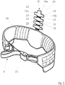
- FIGS. 5 . 6 and 7 show an embodiment in which at least a portion of the connecting element 10 is sprung and / or elastic.
- a rubber joint can be used.
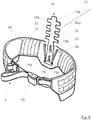
- the Fig. 8 shows a possible variant of a sprung arrangement of the connecting element 10 on the hip belt 3 such that the connecting element 10 is sprung in the vertical direction when the support system 1 is applied correctly and the Carrier of the support system is.
- a spring device 19 is used.
- the spring device 19 is composed of two spring elements 19a, which bias the connecting element 10 in the direction of the protective vest 2.
- the connecting element 10 has two longitudinal slots 19b, in each of which a bolt 19c, which is connected to the hip belt 3, is guided.
- the connecting element 10 When the connecting element 10 is loaded in the direction of the hip belt 3, the connecting element 10 can move downward against the force of the spring elements 19a due to the longitudinal gap 19b, ie in the direction of the hip belt 3, so that a damping between the hip belt 3 and the Protective vest 2 is given. Among other things, this can be sprung footsteps.
- the in Fig. 8 illustrated embodiment represents only one of several possible spring means 19.
- the Fig. 8 illustrated spring means 19 or another may alternatively or additionally also be formed at the end of the connecting element 10 which is fixed to the back part 6.
- the in Fig. 8 illustrated spring device 19 or another spring device with the embodiments of FIGS. 5 to 7 be combined.
- a pivot axis 21 is shown.
- the pivot axis 21 is perpendicular to the surface of the back part 6.
- the connecting element 10 is formed so elastic or spring-loaded and / or sprung on the hip belt 3 or the back part 6 is arranged, that the connecting element 10 is a pivoting movement relative between the back 6 and the hip belt 3 around the perpendicular to the back part 6 extending pivot axis 21 allows.
- Fig. 7 shows an embodiment of the connecting element 10 with damping recesses 20, by which it is possible that the connecting element 10 at a pressure load from the protective vest 2 in the direction of the hip belt 3 (or vice versa) reduces its axial length, that is pushed together.
- the damping recesses 20 preferably extend substantially horizontally in the connecting element 10.
- a plurality of damping recesses 20 are arranged spatially adjacent one another vertically above one another.
- the connecting element 10 may have one or more, preferably vertically superposed elastic or sprung areas.
- the connecting element 10 shown in the embodiment has a substantially flat, plate-shaped structure, wherein the two main surfaces 10a of the plate-shaped structure extend substantially plane-parallel to the back of the back part 6 of the protective vest 2 and wherein the two laterally and vertically extending side edges 10b of the connecting element 10 each have a mirror image arranged, sawtooth-like profile section.
- the sawtooth profile section forms projections 22 and grooves 23.
- the grooves 23 and the projections 22 of the side edges 10b are preferably each mirror image opposite, as shown in the figures.
- FIGS. 5 and 6 show an optional embodiment, in which between two mirror-symmetrically arranged grooves 23 of the profile sections, a portion 24 is formed elastically or sprung.
- a portion 24 is formed elastically or sprung.
- the cuts can z. B. be formed of rubber or rubber.
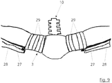
- Fig. 9 shows a further variant of the hip belt 3, which is also feasible in the other embodiments. It is provided that the hip belt 3 has one, preferably two or more zippers 27. In addition, cover tabs 28 may be provided which cover the zipper 27 and a corresponding counterpart. At the zipper 27 additional containers, adapter plates or additional elements can be hung or connected.
- the two in Fig. 9 shown zippers 27 are arranged on the hip belt 3, that they extend in the region of the side of a wearer when the hip belt 3 is applied correctly.
- Fig. 9 optional - also realizable in the other embodiments - a leather trim 29 shown. This is to serve the friction between to increase the hip belt 3 and the wearer and thereby allow a better concern.
- the Fig. 10 Analogously also shows an optional embodiment with two zippers 27 two cover tabs 28 and leather trim 29 on the hip belt. 3
- the connecting element 10 and the back part 6 are preferably configured such that they form a plurality of connecting points in the vertical direction (when the supporting system is correctly supported and the carrier stands), so that a releasable, height-adjustable connection of the connecting element 10 to the back part 6 can be produced.
- the distance between the hip belt 3 and the protective vest 2 can be varied. Two different distances are in the Figures 3 and 4 shown in principle.
- the distance of the connection points can preferably be chosen so that a height adjustment in a grid of 1 to 5 cm, preferably 2.5 cm, is possible.
- connection points which allow a height-offset connection
- Fig. 10 A possible embodiment of such connection points, which allow a height-offset connection, is in Fig. 10 shown.
- Fig. 10 is shown - is provided with a plurality of vertically superposed fastening elements 30, by means of which the connecting element 10 is variably fixed to the back part 6 in height.
- the number of fasteners 30 can be arbitrary.
- six such fasteners 30 are shown vertically above each other.
- the two upper fasteners 30 are in the in Fig. 10 displayed view unused.
- the connecting element 10 is fastened at a higher position of the back part 6 with the aid of the fastening elements 30 located further up.
- the hip belt 3 of the protective vest 2 can be gradually approached or removed.
- Fig. 10 a double arrow drawn.
- fasteners 30 and the formation of the connecting element 10 in this regard arbitrary.
- only one fastening element 30 can be provided.
- Fig. 10 optionally shows a particularly suitable embodiment of the fasteners 30.
- the fasteners 30 are each made up of two mounting tabs 30a together. This is particularly well recognizable from the two top, unused fasteners 30.
- the two fastening tabs 30a of a fastening element 30 are preferably superimposed in the region of the grooves 23 of the connecting element 10 and preferably connected to one another by means of an optionally provided hook-and-loop fastener.
- the fastening elements 30 or the fastening tabs 30a can be connected in any desired manner to the back part 6, for example by riveting, screwing, gluing or the like.
- An optionally provided, particularly preferred possibility, the fastening elements 30 to connect to the back part 6, is in Fig. 11 and 12 shown.
- the back part 6 according to the Fig. 11 and 12 is composed of several layers. For this purpose, a so-called SRM material can be used.
- the back part 6 has an anti-puncture configuration or is formed from a material which provides puncture protection, preferably from an aramid, which is preferably provided with silicon.
- This in Fig. 11 shown back part 6 has a plurality of attachment points 32 for attachment of the fasteners 30 and the mounting tabs 30a or further below with reference to the Fig. 10 shown attachment loops 33.
- the attachment points 32 are in the in Fig. 11 illustrated embodiment integrated into the back part 6. The integration is preferably carried out by the fact that the attachment points 32 already during the pressing of the layers from which the back part 6 according to Fig. 11 composed, integrated.
- the attachment points 32 may preferably be formed as metal inserts.
- the attachment points 32 may have a slot 32a or a through hole. In this case, in each slot 32a or each passage opening, a fastening element 30 or one or two fastening straps 30a or a fastening loop 33 may be attached.
- the back part 6 has one or two, preferably more than two, more preferably two to eight, in particular four, closed layers 600. Furthermore, the back part 6 has one or two, preferably more than two, particularly preferably two to eight, in particular four, slotted layers 601.
- the closed layers 600 form a package of closed layers and the slotted layers 601 form another package of slotted layers.
- the attachment points 32 are pushed through the slots 601a of the package with the slotted layers 601, so that the elongated hole 32a projects beyond the outside of the package from the slotted layers 601.
- the attachment points 32 have on their back, in particular in the region of a foot 32b such a configuration that the attachment point 32 can not be completely pulled through the associated slot 601a, ie that the foot 32b of the attachment point 32 has a dimension which is larger , at least in a relevant direction, as slot 601a.
- the package with the closed layers 600 is attached, so that the foot 32b of the attachment point 32 is fixed between the package of the slotted layers 601 and the package of the closed layers 600 ,
- the layers 600, 601 can then be pressed together, so that a permanent and firm connection is formed.
- the layers 600, 601 may preferably be designed such that they provide puncture protection and / or protection against projectiles.
- Fig. 12 can also be provided to screw the attachment points 32 with the back 6.
- the back part 6 z. B. have an internal thread.
- the back portion 6 has attachment points 32 for attaching the fasteners 30 and the mounting tabs 30a as well as for attaching attachment loops 33 or mounting sleeves. Only in principle is shown how a preferably textile fastening loop 33 could be mounted in the slot 32 a of the attachment point 32.
- the fastening loop 33 has a thickening 33b at its end facing away from the loop part 33a. This ensures that the fastening loop 33 threaded through the slot 32a or retracted, but can not be completed.
- a thickening 33b of the fastening loop 33 can be realized in a particularly simple manner technically.
- the illustrated manner of attaching the attachment loops 33 in the slot 32a is optional and may be realized otherwise.
- the fastening loops 33 or fastening elements 30 or the fastening straps 30a can optionally be attached by analogy.
- Fig. 10 shows an optional and advantageous way to connect the back part 6 facing ends of the fastening belt 8 with the back part 6.
- the fastening belt 8 eyelets 34 and receiving openings.
- the back part 6 according to Fig. 10 is provided with the aforementioned attachment loops 33, which can be connected in any way with the back 6.
- the attachment loops 33 are designed such that they are plugged through the eyelets 34 at the or the ends of the fastening belt 8.
- the fastening belt 8 is provided with eyelets 34 at both ends.
- the fastening belt 8 has two rows of eyelets arranged one above the other at each end. Both are optional. It is sufficient if the fastening strap has eyelets at one end.
- only a single eyelet, a single eyelet row or even several eyelets or eyelet rows, which are arranged one above the other, may be provided.
- Fig. 10 After the attachment loops 33 are inserted through the eyelets 34, is in accordance with Fig. 10 provided that an elongate fixing element 35 by the inserted into the eyelets 34 ends of the fastening loops 33 (more precisely, the loop portion 33 a) is feasible.
- the elongate fixing element 35 is also in Fig. 11 - there dashed - shown. In Fig. 11 However, the eyelets 34 of the fastening belt 8 are not shown.
- the eyelets 34, the attachment loops 33 and the elongated fixing element 35 are such that the attachment loops 33 are no longer executable by the eyelets 34 after passing through the elongated fixing element 35.
- the elongate fixing element 35 has an operating element 36 in order to pull the fixing element 35 out of the fastening loops 33.
- the control is in Fig. 10 only shown schematically. This can be for example to act a simple grip or a loop of the fixing element 35.
- the elongate fixing element 35 may be formed, for example, as a wire or rope, preferably as a plug-in wire.
- the back part 6 has in the in Fig. 10 illustrated embodiment - optional - additional attachment loops 33 through which the fixing element 35 is performed, which are not inserted through eyelets 34 of the fastening belt 8. These fastening loops 33 improve the guidance of the fixing element 35.
- the additional fastening loops 33 also enable a height adjustment of the fastening belt 8 relative to the back part 6.
- the ends of the fastening belt 8 have a plurality of eyelets 34 arranged offset in the circumferential direction of the fastening belt 8.
- the circumference of the fastening belt 8 can be adapted to the wearer.
- an adjustment of the fastening belt 8 is shown around an eyelet 34, ie Fig. 4 shows a fastening strap 8, whose scope relevant to the wearer is greater by one eye spacing.
- Fig. 10 shows is - again optional - provided that at least one, preferably - as shown - both shoulder straps 7 of the protective vest 2 at its the back part 6 end facing at least one eyelet 37 or a receiving opening.
- the invention is described below only with reference to the embodiment with an eyelet 37; However, the invention is not limited thereto, in particular not the exemplary embodiment.
- the back part 6 has the fastening loops 33 already described. In the exemplary embodiment it is provided that in each case a fastening loop 33 in an associated eyelet 37 of the shoulder strap 7 can be inserted. It can be provided per shoulder strap 7 and several eyelets 37 and possibly also a plurality of attachment loops 33.
- each shoulder strap 7 is connected only via a fastening loop 33.
- an elongate fixing element 38 can be guided through the end of the corresponding fastening loop 33 inserted into the eyelet 37.
- the elongated fixing element 38 can in turn be designed as a wire or rope, in particular as a plug-in wire.
- the eyelet 37, the elongated fixing member 38 and the attachment loops 33 may be such that the attachment loop 33 is not executable by the eyelet 37 after passing through the elongated fixing member 38.
- the elongate fixing element 38 may have an operating element 36 in order to pull the fixing element 38 out of the fastening loops 33. It may be the same control element 36, with which also the elongate fixing element 35 can be pulled out. Alternatively or optionally, however, a separate control element 36 for the two fixing elements 35, 38 may be provided.
- the elongated fixing element 38 attaches both shoulder straps 7.
- the elongated fixing element 38 attaches both shoulder straps 7.
- the Attachment loops 33 for connecting a first end of the fastening belt 8 form a first loop row 39, through which a first fixing element 35 is feasible and wherein a second fixing element 38 at least through the attachment loop 33 of the same half of the back part 6 arranged first shoulder strap 7 is feasible and the first and second fixing elements 35, 38 can be pulled out of the fastening loops 33 by a common operating part 36 in order to detach the first end of the fastening belt 8 and at least the first shoulder strap 7 from the back part 8.
- a third elongated fixing element 40 which serves to fasten a second end of the fastening belt 8 to the back part 6.
- the third elongate fixing member 40 is in the in Fig. 10 illustrated embodiment of the other two elongated fixing elements 35, 38 independently operable and has for this purpose at its end facing away from the fastening strap 8 end an operating loop on.
- the in Fig. 10 illustrated fastening strap 8 optionally has at least one zipper 41.
- two zippers 41 which are each located in the region of the side of a human upper body, when the fastening belt 8 is applied correctly.
- a cover tab 42 is provided for each zipper, which covers the zipper 41 respectively. With the help of the zipper 41 z. B. adapter plates are attached.
- FIG. 10 Mounting tabs 44 formed, but for reasons of clarity based on the FIGS. 2 to 4 to be discribed.
- a back cushion 43 may optionally be attached to the human upper body facing the inside of the back part 6 of the protective vest 2, a back cushion 43.
- the connection of the back pad 43 on the inside of the back part 6 is preferably carried out via a not shown Velcro connection, whereby a height adjustment can be achieved.
- the Velcro connection is optionally also provided on the inside of the back part 6 shown there.
- the fixation of the back pad 43 is carried out alternatively or in addition to the already described Velcro connection in the embodiment also by the fact that the back part 6 has fastening tabs 44.
- one or more fastening straps 44 may be provided.
- the fastening tabs 44 are folded after the positioning of the back pad 43 on the human upper body facing the inside of the back pad 43 and fixed there preferably via a Velcro connection.
- the Fig. 2 shows the fastening tabs 44 in an open state.
- the Figures 3 and 4 show a view in which the fastening tabs 44 are opened to the human upper body facing the inside of the back pad 43. Ie. the fastening tabs 44 are closed.
- a Velcro fastener shown in the FIGS. 2 to 4 is on the human upper body facing inside of the back pad 43rd a Velcro fastener shown.
- the back pad 43 has Velcro zones.
- a corresponding Velcro fastener 44 is indicated on the fastening tabs.
- the back pad 43 may optionally be provided with a weft and / or anti-puncture security insert, a so-called ballistic insert, and / or the back pad 43 may also optionally have a slot for a shot and / or stab-resistant security insert.
- the security insert may preferably be a hartballmaschine plate, z. As ceramic, preferably packed in aramids act.
- the advantage is a purely ballistic (hard and / or soft ballistic) embodiment of the security deposits in conjunction with a slot in the back cushion 43.
- the ballistic security deposit can be removed when a ballistic protection is not required.
- Fig. 13 shows a further possible optional embodiment for the embodiments, but this is not limited thereto should be.
- Fig. 13 shows a shoulder strap guide member 45, which is shown in a slightly different design and simplified in the Fig. 10 is provided (also optional there).
- This in Fig. 13 shown shoulder strap guide member 45 is attached to the back part 6 such that between the shoulder strap guide member 45 and the back part 6, a longitudinal gap 46 remains, which makes it possible to perform the attachment provided with the back part 6 end of a shoulder strap 7.
- the shoulder strap guide element 45 is arranged above a fastening loop 33 of the back part 6, which is provided for fixing the shoulder strap 7. In this regard, the presentation according to Fig. 10 directed.
- the shoulder belt guide member 45 By the shoulder belt guide member 45, a linkage for the shoulder strap 7 is achieved, whereby the guide improves and the fastening loop 33 is relieved.
- the shoulder strap guide member 45 is formed only as a simple plate, which is attached to the back part 6 according to, preferably screwed, is.
- the shoulder strap guide member 45 comprises a rotatable pin or generally a rotatable elongate member which can rotate when the shoulder strap 7 is inserted or extended in the longitudinal gap 46.
- Fig. 13 further shows that the shoulder strap guide member 45 may have holes 48 provided for passing screws (not shown) to screw the shoulder strap guide member 45 to the back piece 6.
- Fig. 15 shows an alternative way to form an attachment point 32.
- the attachment point 32 is suitable For example, it is a shoulder strap guide member 45, such as in Fig. 13 is shown to be attached to the back part 6.
- the attachment point 32 can also be used for attaching attachment loops 33 or attachment elements 30 or fastening straps 30a.
- the back portion 6 may have any structure, for example, also as such with respect to the embodiment according to Fig. 12 was described in more detail. All of the above embodiments can be with the attachment point 32, as this in Fig. 15 is shown, combine.
- the attachment point 32 is formed by the fact that the back part 6 is provided with a through hole 602.
- the attachment point 32 is formed as an insert, in the exemplary embodiment as a sleeve, preferably as a threaded sleeve, in particular with an internal thread 320.
- the threaded sleeve 32 is inserted into the bore 602 and fixed there.
- several variants are conceivable. It is particularly advantageous, as in Fig. 15 shown, when the threaded sleeve 32 has at one end a circumferential collar 321 which has a diameter which is at least partially greater than the inner diameter of the bore 602.
- a counter-disc 49 is attached or postponed.
- the end facing away from the collar 321 is crimped, so that reinforced by the counter pulley 49, a reliable fixation of the threaded sleeve 32 in the bore 602 takes place.
- various elements can be screwed or fastened into the internal thread 23.
- the shoulder strap guide member 45 may preferably be screwed directly by means of one or more screws.
- the fastening loops 32 and / or the fastening elements 30 or the fastening straps 30a can also be screwed directly by means of a screw.
- the fastening loop 32 and / or the fastening element 30 or the fastening tongue 30a can have a screw through-hole, through which the screw is inserted and subsequently screwed to the threaded sleeve 32.
- the screw can also be screwed directly through the fastening loop 32 and / or the fastening element 30 or the fastening tab 30a.
- a screw through hole is not absolutely necessary.
- an unillustrated additional element is screwed, which has a slot 32a or a slot, analogous to the representation of the attachment point 32 in Fig. 11 .
- a fastening loop 32 and a fastener 30 and a fastening tab 30a inserted and fixed there, as in Fig. 11 is shown and described.
- the Fig. 16 shows the assembly, which is composed of the threaded sleeve 32 and the counter pulley 49, in detail.
- a formation of an attachment point by means of a through hole 602 in the back part 6 can be done in various ways, in particular the above with reference to FIGS. 15 and 16 described embodiment is not limited to the fact that it is a threaded sleeve 32nd is. In principle, it may be an arbitrary insert, which allows a fixation in the bore 602.
- Fig. 17 shows a possible alternative embodiment of the hip belt 3 with a hip belt insert 100.
- the hip belt insert 100 is in Fig. 17 shown in dashed lines.
- the hip belt insert 100 is formed integrally with the connecting element 10.
- the hip belt insert 100 extends in the exemplary embodiment Fig. 17 at least partially in the circumferential direction of the hip belt 3 or forms the course of the hip belt 3 at least over a portion preferably at least approximately completely after.
- the hip belt insert 100 is integrated in the exemplary embodiment in the hip belt 3, that is, the hip belt 3 receives the hip belt insert 100, so that the hip belt insert 100 is surrounded by textile material or by the hip belt 3, preferably at least in the areas on a human body when the hip belt 3 is worn correctly.
- the waist belt pad 100 may be formed of rubber, rubber or a similar elastic material. It can be provided that the hip belt insert 100 is formed from a plurality of layers of rubber, rubber or a similar elastic material. Preferably, the layers may be combined with textile layers and preferably laminated to form a composite.
- the hip belt pad 100 is preferably a sheet material.
- the hip belt pad 100 may be provided with cushioning recesses 101 that facilitate deformation of the waist belt pad 100 so that the waist belt pad 100 is particularly well able to absorb vertical forces acting from the protective vest 2 over the connector 10. In the embodiment, the formation of a damping recess 101 is shown, the is vertically below the connecting element 10 and so can dampen particularly well vertical forces. However, alternatively, a plurality of damping recesses 101 may be provided at different locations.
- hip belt insert 100 has proven to be particularly suitable for absorbing forces. All based on the FIGS. 1 to 16 illustrated embodiments can be combined with a hip belt insert 100, which has a connecting element 10 as an integral part. It does not depend on the specific design of the connecting element 10, for example with a sawtooth profile, or its connection to the back part 6.
- the modular support system 1 with a back pad 43, which by a Velcro connection height adjustable on the back part 6 of the protective vest 2 is attached and which is additionally fixable via the fastening tabs 44.
- the back part 6 is provided with attachment loops 33 and the means for attachment to a human upper body, based on the protective vest 2, eyelets 34, 37, which together with the attachment loops 33 and a elongate fixing member 35, 38 cause the means for attachment to a human upper body (shoulder strap 7 and / or Befest Trentsgurt 8) on the elongated fixing elements 35, 38 releasably attached to the back part 6, wherein the elongate fixing element 35, 38 is an operating element 36, to pull out the corresponding fixing element 35, 38.
- the aforementioned solutions can be used both individually and in combination.
Claims (9)
- Système de portage modulaire (1) comprenant au moins un des composants de système suivants :a. une veste de protection (2) avec au moins une partie dorsale (6) et des moyens (7, 8) pour la fixation sur une partie supérieure d'un corps humain,b. une ceinture (3),c. une installation de portage (4) configurée pour être remplie avec des charges à porter, l'installation de portage (4) comportant des courroies d'épaules (4a) pour être fixées sur une partie supérieure d'un corps humain, etd. un conteneur (5) pour loger une unité électronique, le conteneur (5) pouvant être adapté sur le côté arrière de la veste de protection (2),dans lequel la ceinture (3) comporte un élément de liaison (10), pour connecter la veste de protection (2) au conteneur (5), sans connexion intermédiaire, dans lequel l'élément de liaison (10) est configuré pour transmettre des forces de poids de la veste de protection (2) sur la ceinture (3), caractérisé en ce qu'au moins un des deux bords (10b) latéraux, s'étendant sur les côtés et verticalement, de l'élément de liaison (10) forme un profil en dents de scie pourvu de protubérances (22) et de nervures (23).
- Système de portage (1) selon la revendication 1,
caractérisé en ce que,
l'élément de liaison (10) est formé à la partie dorsale de la ceinture (3) et s'étend le long d'une colonne vertébrale humaine, vers le haut, le long du dos, lorsque la ceinture (3) est correctement appuyée, dans lequel le secteur supérieur de l'élément de liaison (10), éloigné par rapport à la ceinture (3), peut être couplé avec la partie arrière (6) de la veste de protection (2). - Système de portage (1) selon les revendications 1 ou 2,
caractérisé en ce que,
au moins une pièce partielle (24) de l'élément de liaison (10) est réalisée sous forme ressort ou élastique et/ou, l'élément de liaison (10) est monté avec un ressort dans la direction verticale sur la ceinture (3) et/ou fixé à la veste de protection (2), et/ou l'élément de liaison (10) peut effectuer un mouvement de pivotement relatif entre la partie dorsale (6) de la veste de protection (2) et la ceinture (3) pour former un axe de pivotement vertical (21) par rapport à la partie dorsale (6). - Système de portage (1) selon l'une des revendications 1 à 3,
caractérisé en ce que,
la ceinture (3) présente une connexion (11) pour coupler l'installation de portage (4) à la ceinture (3) sans couplage intermédiaire du conteneur (5) avec la ceinture (3). - Système de portage (1) selon l'une des revendications 1 à 4,
caractérisé en ce que,
l'élément de liaison (10) présente essentiellement une structure plate, en forme de plateforme, dans lequel les surfaces principales (10a) de la surface en forme de plateforme s'étendent essentiellement de façon plane et parallèlement au côté arrière de la partie dorsale (6) de la veste de protection (2) et, dans lequel les deux bords des côtés (10b) s'étendant latéralement et verticalement, de l'élément de liaison (10) présentent respectivement une disposition symétrique et un profil ayant une section en dents de scie. - Système de portage (1) selon l'une des revendications 1 à 5,
caractérisé en ce que,
la face intérieure de la partie dorsale (6) est pourvue de plusieurs éléments de fixation (30) superposés, avec lesquels l'élément de liaison (10) de la ceinture (3) sur la partie dorsale (6) peut être fixé de façon variable en hauteur. - Système de portage (1) selon la revendication 6,
caractérisé en ce que,
chaque élément de fixation (30) comporte deux flasques de fixation (30a) qui sont superposés dans le secteur des nervures (23) des éléments de liaison (10) et sont avantageusement couplés ensemble, au moyen d'un verrouillage du type velcro (31). - Système de portage (1) selon l'une des revendications 1 à 7,
caractérisé en ce que,
au moins entre deux nervures (23) symétriquement disposées, une pièce restante (24) de l'élément de liaison (10) est réalisée sous forme élastique ou ressort. - Système de portage (1) selon l'une des revendications 1 à 8,
caractérisé en ce que,
les moyens (7, 8) pour la fixation à la partie supérieure d'un corps humain, comportent une courroie de fixation (8) disposée au-dessus de la ceinture (3) et/ou deux courroies d'épaules (7) s'étendant par-dessus les épaules d'un homme, lesquelles peuvent être fixées à, ou respectivement montées sur la partie dorsale (6) de la veste de protection (2), et, les extrémités orientées vers la partie dorsale (6) de la courroie de fixation (8) sont pourvues d'oeillets (34) ou d'ouvertures réceptrices ménagées sur la partie dorsale (6) de boucles de fixation (33), dans lequel les boucles de fixation (33) peuvent être engagées à travers les oeillets (34) ou les ouvertures réceptrices, et dans lequel au moins un élément de fixation allongé (35) est prévu pour guider les extrémités des boucles de fixation (33) à travers le oeillets (34) ou les ouvertures réceptrices, et l'élément de fixation allongé (35) est configuré de telle manière que les boucles de fixation (33), après le passage de l'élément de fixation allongé (35), ne peuvent plus être retirées des oeillets (34) ou des ouvertures réceptrices, dans lequel l'élément de fixation allongé (35) comporte un élément de service (36) pour retirer l'élément de fixation (35) des boucles de fixation (33).
Applications Claiming Priority (2)
| Application Number | Priority Date | Filing Date | Title |
|---|---|---|---|
| DE102011075683A DE102011075683A1 (de) | 2011-05-11 | 2011-05-11 | Modulares Tragsystem |
| PCT/EP2012/058628 WO2012152863A2 (fr) | 2011-05-11 | 2012-05-10 | Système de transport modulaire |
Publications (2)
| Publication Number | Publication Date |
|---|---|
| EP2706884A2 EP2706884A2 (fr) | 2014-03-19 |
| EP2706884B1 true EP2706884B1 (fr) | 2017-08-30 |
Family
ID=46046236
Family Applications (1)
| Application Number | Title | Priority Date | Filing Date |
|---|---|---|---|
| EP12719743.2A Active EP2706884B1 (fr) | 2011-05-11 | 2012-05-10 | Système de transport modulaire |
Country Status (5)
| Country | Link |
|---|---|
| US (1) | US20140151424A1 (fr) |
| EP (1) | EP2706884B1 (fr) |
| DE (1) | DE102011075683A1 (fr) |
| NO (1) | NO2706884T3 (fr) |
| WO (1) | WO2012152863A2 (fr) |
Families Citing this family (54)
| Publication number | Priority date | Publication date | Assignee | Title |
|---|---|---|---|---|
| IL210054A0 (en) * | 2010-12-16 | 2011-02-28 | Source Vagabond Systems Ltd | Load carrier device |
| US20130193179A1 (en) * | 2012-01-27 | 2013-08-01 | Joseph M. Davidson | Equipment-storage/carrying apparatus |
| US8857681B2 (en) * | 2012-03-08 | 2014-10-14 | The United States Of America As Represented By The Secretary Of The Air Force | Load carriage connector and system |
| NL2008784C2 (en) * | 2012-05-09 | 2013-11-12 | Toto Carrying Systems B V | Load carrying system. |
| US9993039B2 (en) | 2012-11-30 | 2018-06-12 | 5.11, Inc. | Garment with plate carrying system |
| US9820514B2 (en) * | 2012-11-30 | 2017-11-21 | 5.11, Inc. | Garment with carrying system |
| US20150342329A1 (en) * | 2012-12-17 | 2015-12-03 | Rig Equipment Limited | Vest |
| US20160022017A1 (en) * | 2013-03-10 | 2016-01-28 | Marom Dolphin Ltd. | Improved personal carrier |
| GB201304542D0 (en) * | 2013-03-13 | 2013-04-24 | Bcb Int Ltd | Dynamic load carriage frame |
| IL226809B (en) | 2013-06-06 | 2018-11-29 | Jonathan Bar Or | Adjustable device for carrying loads |
| US9220333B2 (en) * | 2013-11-27 | 2015-12-29 | Msa Technology, Llc | Adjustable lumbar support for mounting on a backpack and backpack having the same |
| GB201404465D0 (en) * | 2014-03-13 | 2014-04-30 | Secr Defence | A body armour system |
| US10288384B2 (en) * | 2014-07-29 | 2019-05-14 | Brady Alan Robinson Kinnings | Tactical load-bearing vest |
| US9664481B2 (en) * | 2014-08-07 | 2017-05-30 | 5.11, Inc. | Hexagonal attachment system |
| DE102014018836A1 (de) * | 2014-12-15 | 2016-06-16 | Sten Wallenaar | Tragevorrichtung für Körperschutzausstattung (KSA) hüftgestützte KSA |
| US9756920B2 (en) * | 2015-03-31 | 2017-09-12 | Candace Spears | Backpack with removable straps and adjustable belts |
| US11311062B2 (en) | 2015-04-30 | 2022-04-26 | Point Blank Enterprises, Inc. | Impact reduction system |
| US10368626B2 (en) * | 2015-04-30 | 2019-08-06 | Point Blank Enterprises, Inc. | Carrier system and subassembly thereof |
| US9486058B1 (en) * | 2015-06-01 | 2016-11-08 | Ty-Flot, Inc. | Tool vest |
| US10220789B2 (en) * | 2015-06-08 | 2019-03-05 | Ben Ross Crowe | Baggage restraint system |
| US20160360864A1 (en) * | 2015-06-12 | 2016-12-15 | Bryan Lee Drake | Bullet proof vest with backpack |
| US9820556B2 (en) * | 2015-06-16 | 2017-11-21 | Xpansion Gear, Llc | System for storing, organizing, and transporting portable items |
| US10034533B1 (en) * | 2015-09-04 | 2018-07-31 | Jose Luis Santana-Zaizar | Backpack system |
| ITUB20154255A1 (it) * | 2015-10-09 | 2017-04-09 | Mech Lab S R L | Struttura indossabile di supporto di protezioni balistiche e/o equipaggiamenti militari |
| US10495418B2 (en) * | 2016-01-14 | 2019-12-03 | Angel Armor, Llc | Releasably engagable system of ballistic resistant panels |
| US10004320B2 (en) * | 2016-05-10 | 2018-06-26 | Amer Sports Canada Inc. | Hipbelt suspension system for use with a backpack |
| IL247012B (en) * | 2016-07-28 | 2021-05-31 | Marom Dolphin Ltd | author |
| US10004936B1 (en) * | 2016-12-16 | 2018-06-26 | Cade Ekstrom | Multifunctional training and workout harness |
| US10542816B1 (en) * | 2017-04-03 | 2020-01-28 | Caleb J. Newton | Gear and device holding harness system |
| GB2563864B (en) * | 2017-06-27 | 2022-01-12 | Draeger Safety Uk Ltd | Harness for breathing apparatus |
| US10010160B1 (en) * | 2017-07-21 | 2018-07-03 | Mollotek Llc | Load-supporting garment |
| DE102017008754A1 (de) * | 2017-09-15 | 2019-03-21 | Andreas Stihl Ag & Co. Kg | Tragvorrichtung zum Tragen eines handgeführten Arbeitsgerätes durch einen Benutzer |
| US11058210B2 (en) * | 2017-09-27 | 2021-07-13 | Globe (jiangsu) Co., Ltd. | Pivotal carrier assembly for a harness |
| WO2019061091A1 (fr) * | 2017-09-27 | 2019-04-04 | Changzhou Globe Co., Ltd. | Ensemble de support réglable pour un harnais |
| IL256653A (en) * | 2017-12-28 | 2018-02-28 | Source Vagabond Systems Ltd | Tactical vest with height adjustment |
| USD866166S1 (en) * | 2018-01-12 | 2019-11-12 | Dennis Ho | Backpack having integrated solar panels |
| USD878053S1 (en) | 2018-05-31 | 2020-03-17 | Camelbak Products, Llc | Pack panel |
| JP7177652B2 (ja) * | 2018-10-11 | 2022-11-24 | 株式会社マキタ | 背負式機器 |
| CN109512563B (zh) * | 2018-11-19 | 2021-01-26 | 河南省中医院(河南中医药大学第二附属医院) | 人体脊柱保护架 |
| US11243050B2 (en) | 2018-11-28 | 2022-02-08 | 5.11, Inc. | Plate carrier absorption of shock from movement of wearer |
| US20200217622A1 (en) * | 2019-01-04 | 2020-07-09 | Hilario Felix James, Jr. | DEFEND A PACK a bulletproof vest with backpack attached all-in-one |
| WO2021101443A1 (fr) * | 2019-11-18 | 2021-05-27 | Advanced Material Engineering Pte Ltd | Système de sac à dos tactique |
| USD946281S1 (en) * | 2019-12-11 | 2022-03-22 | VisioPlan GmbH | Backpack clip |
| NO20200720A1 (en) * | 2020-01-07 | 2021-07-08 | Ethic Games Sp Z O O | Saddle arrangements for rucksacks and methods of manufacture |
| USD984119S1 (en) * | 2020-04-29 | 2023-04-25 | Jose De Abreu | Tactical backpack |
| USD1021383S1 (en) * | 2020-06-09 | 2024-04-09 | Nfinity Ip, Llc | Backpack with removable fanny pack |
| JP1689962S (fr) * | 2020-06-26 | 2021-07-12 | ||
| USD919962S1 (en) * | 2020-11-19 | 2021-05-25 | Xinliang SHI | Motorcycle helmet backpack |
| USD944515S1 (en) * | 2021-01-26 | 2022-03-01 | Dong Ji | Backpack |
| IT202100025535A1 (it) * | 2021-10-07 | 2023-04-07 | Davide Giribaldi | Capo indossabile ad uso militare |
| DE102021127397A1 (de) * | 2021-10-21 | 2023-04-27 | Hunic Gmbh | Vorrichtung zur Unterstützung beim Tragen von Lasten |
| USD968075S1 (en) * | 2022-03-16 | 2022-11-01 | Junhua Liu | Backpack |
| USD977244S1 (en) * | 2022-08-15 | 2023-02-07 | MAH Group, Inc | Backpack |
| USD984799S1 (en) * | 2022-10-09 | 2023-05-02 | Quanzhou Jingbo Trading Co., Ltd. | Backpack |
Family Cites Families (24)
| Publication number | Priority date | Publication date | Assignee | Title |
|---|---|---|---|---|
| US2093326A (en) * | 1936-06-05 | 1937-09-14 | Prentice G E Mfg Co | Key support |
| US3557384A (en) * | 1969-02-24 | 1971-01-26 | Us Army | Variable infantry armor system |
| US3902640A (en) * | 1974-03-19 | 1975-09-02 | John J Geiben | Hiker{3 s back pack |
| US4676418A (en) * | 1986-03-12 | 1987-06-30 | Lowe Alpine Systems, Inc. | Backpack having improved load distribution and stabilizing structures |
| US5184763A (en) | 1991-10-16 | 1993-02-09 | Blaisdell Richard W | Modular, free movement backpack system |
| US5503314A (en) | 1994-06-21 | 1996-04-02 | Fiscus; Wayne R. | Helixical backpack carrier |
| US5609278A (en) * | 1994-11-18 | 1997-03-11 | Fresco; Andre | Articulated backpack apparatus |
| DE10033738A1 (de) * | 2000-01-10 | 2002-01-24 | Ekkehard Gorski | Trage-bzw. Haltevorrichtung |
| US6536641B1 (en) * | 2000-06-08 | 2003-03-25 | Original Design Group | Back-mounted load-carrying apparatus |
| RU2234842C1 (ru) * | 2003-05-23 | 2004-08-27 | Михеев Владимир Григорьевич | Многофункциональный жилет |
| US20050082330A1 (en) * | 2003-10-20 | 2005-04-21 | Fehlberg Eric O. | Pack support with frictional load transfer |
| US8079503B1 (en) * | 2006-02-08 | 2011-12-20 | Blackhawk Industries Product Group Unlimited Llc | Modular equipment coupler |
| EP1842449A1 (fr) | 2006-04-05 | 2007-10-10 | Nederlandse Organisatie voor Toegepast-Natuuurwetenschappelijk Onderzoek TNO | Système personnel de portage |
| US9204708B2 (en) * | 2006-05-12 | 2015-12-08 | Nike, Inc. | Strap incorporating a fluid-filled bladder |
| US20090282595A1 (en) * | 2006-05-30 | 2009-11-19 | The Board Of Regents For Oklahoma State University | Antiballistic Garment |
| IL176659A0 (en) * | 2006-07-02 | 2007-07-04 | Kata | A personal load-bearing system |
| US8418265B1 (en) * | 2006-08-25 | 2013-04-16 | Alliant Techsystems Inc. | Releasable vest |
| WO2008089128A2 (fr) | 2007-01-12 | 2008-07-24 | Emerald Touch, Inc. | Système de support corporel individuel |
| US8490212B1 (en) * | 2007-02-05 | 2013-07-23 | Eagle Industries Unlimited, Inc. | Quick release garment |
| EP2203076A4 (fr) * | 2007-11-01 | 2013-09-04 | Alliant Techsystems Inc | Gilet libérable |
| US8919628B2 (en) | 2007-11-16 | 2014-12-30 | Morris James R. Jamlang | Modular backpack and a method for using same |
| GB0806359D0 (en) * | 2008-04-08 | 2008-05-14 | Scott Health & Safety Ltd | Carrying system for breathing apparatus |
| EP2448445A4 (fr) * | 2009-06-30 | 2013-12-25 | Lineweight Llc | Dispositif personnel de distribution de charges |
| DE102009042455B4 (de) | 2009-09-23 | 2016-03-17 | Hexonia Gmbh | Tragsystem mit einer ballistischen Schutzweste |
-
2011
- 2011-05-11 DE DE102011075683A patent/DE102011075683A1/de active Pending
-
2012
- 2012-05-10 WO PCT/EP2012/058628 patent/WO2012152863A2/fr active Application Filing
- 2012-05-10 NO NO12719743A patent/NO2706884T3/no unknown
- 2012-05-10 US US14/117,001 patent/US20140151424A1/en not_active Abandoned
- 2012-05-10 EP EP12719743.2A patent/EP2706884B1/fr active Active
Non-Patent Citations (1)
| Title |
|---|
| None * |
Also Published As
| Publication number | Publication date |
|---|---|
| DE102011075683A1 (de) | 2012-11-15 |
| WO2012152863A3 (fr) | 2013-05-10 |
| EP2706884A2 (fr) | 2014-03-19 |
| US20140151424A1 (en) | 2014-06-05 |
| WO2012152863A2 (fr) | 2012-11-15 |
| NO2706884T3 (fr) | 2018-01-27 |
Similar Documents
| Publication | Publication Date | Title |
|---|---|---|
| EP2706884B1 (fr) | Système de transport modulaire | |
| EP2387909B1 (fr) | Système de support doté d'un élément frontal et arrière et moyens de fixation sur le buste d'un corps humain | |
| DE60100845T2 (de) | Schutzhelm mit vorrichtung zum verstellen der kopfweite | |
| EP2387910A2 (fr) | Système de support | |
| DE102009042455B4 (de) | Tragsystem mit einer ballistischen Schutzweste | |
| EP3357371A1 (fr) | Système porteur pour sac à dos destiné transport dorsal mains libres d'un vélo | |
| DE102013222372B4 (de) | Beschlagelement für Auffanggurtsystem und Auffanggurtsystem | |
| DE102006028711B4 (de) | Gepäckstück mit Rollenziehsystem und Teleskopauszug, versehen mit einem Rückentragesystem | |
| DE112012001093T5 (de) | Tragrahmen für eine Rückenlast | |
| AT513781B1 (de) | Sicherheitsanzug | |
| DE102010029037B4 (de) | Ballistische Schutzweste | |
| DE102008062393B4 (de) | In eine vordere Position umlagerbarer Rucksack | |
| EP3565434A1 (fr) | Sangle de support servant à porter sur le corps une caméra ou un appareil photo | |
| EP1201511B1 (fr) | Dispositif de déflexion de forces pour l'adaption d' une ceinture au niveau du bassin | |
| DE102007029572A1 (de) | Haltevorrichtung zum Entlasten der Wirbelsäule in der Sitzposition | |
| DE102010038699A1 (de) | Tragevorrichtung zum Tragen von Lasten | |
| DE202013100486U1 (de) | Traggeschirr zum Tragen von Gegenständen | |
| DE102022119727A1 (de) | Tragesystem für einen Ausrüstungsgegenstand | |
| EP2684486B1 (fr) | Sac à dos avec lien supplémentaire et rembourrages | |
| WO2018178195A1 (fr) | Dispositif pour transporter un blessé, en particulier une personne incapable de marcher | |
| DE102017218477A1 (de) | Bergevorrichtung | |
| WO2023135331A1 (fr) | Système interne pour casque de sécurité | |
| DE60314759T3 (de) | Schulterträger mit elastischem verstellbarem Spanner | |
| DE102010029042A1 (de) | Trägersystem und Hüftgurt | |
| WO2023274983A1 (fr) | Orthèse thoracique |
Legal Events
| Date | Code | Title | Description |
|---|---|---|---|
| PUAI | Public reference made under article 153(3) epc to a published international application that has entered the european phase |
Free format text: ORIGINAL CODE: 0009012 |
|
| 17P | Request for examination filed |
Effective date: 20131126 |
|
| AK | Designated contracting states |
Kind code of ref document: A2 Designated state(s): AL AT BE BG CH CY CZ DE DK EE ES FI FR GB GR HR HU IE IS IT LI LT LU LV MC MK MT NL NO PL PT RO RS SE SI SK SM TR |
|
| DAX | Request for extension of the european patent (deleted) | ||
| 17Q | First examination report despatched |
Effective date: 20160307 |
|
| GRAP | Despatch of communication of intention to grant a patent |
Free format text: ORIGINAL CODE: EPIDOSNIGR1 |
|
| INTG | Intention to grant announced |
Effective date: 20170309 |
|
| GRAS | Grant fee paid |
Free format text: ORIGINAL CODE: EPIDOSNIGR3 |
|
| GRAA | (expected) grant |
Free format text: ORIGINAL CODE: 0009210 |
|
| AK | Designated contracting states |
Kind code of ref document: B1 Designated state(s): AL AT BE BG CH CY CZ DE DK EE ES FI FR GB GR HR HU IE IS IT LI LT LU LV MC MK MT NL NO PL PT RO RS SE SI SK SM TR |
|
| REG | Reference to a national code |
Ref country code: GB Ref legal event code: FG4D Free format text: NOT ENGLISH |
|
| REG | Reference to a national code |
Ref country code: CH Ref legal event code: EP |
|
| REG | Reference to a national code |
Ref country code: AT Ref legal event code: REF Ref document number: 922669 Country of ref document: AT Kind code of ref document: T Effective date: 20170915 |
|
| REG | Reference to a national code |
Ref country code: IE Ref legal event code: FG4D Free format text: LANGUAGE OF EP DOCUMENT: GERMAN |
|
| REG | Reference to a national code |
Ref country code: DE Ref legal event code: R096 Ref document number: 502012011145 Country of ref document: DE |
|
| REG | Reference to a national code |
Ref country code: SE Ref legal event code: TRGR |
|
| REG | Reference to a national code |
Ref country code: NL Ref legal event code: FP |
|
| REG | Reference to a national code |
Ref country code: LT Ref legal event code: MG4D |
|
| PG25 | Lapsed in a contracting state [announced via postgrant information from national office to epo] |
Ref country code: HR Free format text: LAPSE BECAUSE OF FAILURE TO SUBMIT A TRANSLATION OF THE DESCRIPTION OR TO PAY THE FEE WITHIN THE PRESCRIBED TIME-LIMIT Effective date: 20170830 Ref country code: FI Free format text: LAPSE BECAUSE OF FAILURE TO SUBMIT A TRANSLATION OF THE DESCRIPTION OR TO PAY THE FEE WITHIN THE PRESCRIBED TIME-LIMIT Effective date: 20170830 Ref country code: LT Free format text: LAPSE BECAUSE OF FAILURE TO SUBMIT A TRANSLATION OF THE DESCRIPTION OR TO PAY THE FEE WITHIN THE PRESCRIBED TIME-LIMIT Effective date: 20170830 |
|
| REG | Reference to a national code |
Ref country code: NO Ref legal event code: T2 Effective date: 20170830 |
|
| PG25 | Lapsed in a contracting state [announced via postgrant information from national office to epo] |
Ref country code: RS Free format text: LAPSE BECAUSE OF FAILURE TO SUBMIT A TRANSLATION OF THE DESCRIPTION OR TO PAY THE FEE WITHIN THE PRESCRIBED TIME-LIMIT Effective date: 20170830 Ref country code: GR Free format text: LAPSE BECAUSE OF FAILURE TO SUBMIT A TRANSLATION OF THE DESCRIPTION OR TO PAY THE FEE WITHIN THE PRESCRIBED TIME-LIMIT Effective date: 20171201 Ref country code: IS Free format text: LAPSE BECAUSE OF FAILURE TO SUBMIT A TRANSLATION OF THE DESCRIPTION OR TO PAY THE FEE WITHIN THE PRESCRIBED TIME-LIMIT Effective date: 20171230 Ref country code: LV Free format text: LAPSE BECAUSE OF FAILURE TO SUBMIT A TRANSLATION OF THE DESCRIPTION OR TO PAY THE FEE WITHIN THE PRESCRIBED TIME-LIMIT Effective date: 20170830 Ref country code: ES Free format text: LAPSE BECAUSE OF FAILURE TO SUBMIT A TRANSLATION OF THE DESCRIPTION OR TO PAY THE FEE WITHIN THE PRESCRIBED TIME-LIMIT Effective date: 20170830 Ref country code: BG Free format text: LAPSE BECAUSE OF FAILURE TO SUBMIT A TRANSLATION OF THE DESCRIPTION OR TO PAY THE FEE WITHIN THE PRESCRIBED TIME-LIMIT Effective date: 20171130 |
|
| PG25 | Lapsed in a contracting state [announced via postgrant information from national office to epo] |
Ref country code: CZ Free format text: LAPSE BECAUSE OF FAILURE TO SUBMIT A TRANSLATION OF THE DESCRIPTION OR TO PAY THE FEE WITHIN THE PRESCRIBED TIME-LIMIT Effective date: 20170830 Ref country code: DK Free format text: LAPSE BECAUSE OF FAILURE TO SUBMIT A TRANSLATION OF THE DESCRIPTION OR TO PAY THE FEE WITHIN THE PRESCRIBED TIME-LIMIT Effective date: 20170830 Ref country code: PL Free format text: LAPSE BECAUSE OF FAILURE TO SUBMIT A TRANSLATION OF THE DESCRIPTION OR TO PAY THE FEE WITHIN THE PRESCRIBED TIME-LIMIT Effective date: 20170830 Ref country code: RO Free format text: LAPSE BECAUSE OF FAILURE TO SUBMIT A TRANSLATION OF THE DESCRIPTION OR TO PAY THE FEE WITHIN THE PRESCRIBED TIME-LIMIT Effective date: 20170830 |
|
| REG | Reference to a national code |
Ref country code: FR Ref legal event code: PLFP Year of fee payment: 7 |
|
| PG25 | Lapsed in a contracting state [announced via postgrant information from national office to epo] |
Ref country code: IT Free format text: LAPSE BECAUSE OF FAILURE TO SUBMIT A TRANSLATION OF THE DESCRIPTION OR TO PAY THE FEE WITHIN THE PRESCRIBED TIME-LIMIT Effective date: 20170830 Ref country code: SM Free format text: LAPSE BECAUSE OF FAILURE TO SUBMIT A TRANSLATION OF THE DESCRIPTION OR TO PAY THE FEE WITHIN THE PRESCRIBED TIME-LIMIT Effective date: 20170830 Ref country code: EE Free format text: LAPSE BECAUSE OF FAILURE TO SUBMIT A TRANSLATION OF THE DESCRIPTION OR TO PAY THE FEE WITHIN THE PRESCRIBED TIME-LIMIT Effective date: 20170830 Ref country code: SK Free format text: LAPSE BECAUSE OF FAILURE TO SUBMIT A TRANSLATION OF THE DESCRIPTION OR TO PAY THE FEE WITHIN THE PRESCRIBED TIME-LIMIT Effective date: 20170830 |
|
| REG | Reference to a national code |
Ref country code: DE Ref legal event code: R097 Ref document number: 502012011145 Country of ref document: DE |
|
| PLBE | No opposition filed within time limit |
Free format text: ORIGINAL CODE: 0009261 |
|
| STAA | Information on the status of an ep patent application or granted ep patent |
Free format text: STATUS: NO OPPOSITION FILED WITHIN TIME LIMIT |
|
| 26N | No opposition filed |
Effective date: 20180531 |
|
| PG25 | Lapsed in a contracting state [announced via postgrant information from national office to epo] |
Ref country code: SI Free format text: LAPSE BECAUSE OF FAILURE TO SUBMIT A TRANSLATION OF THE DESCRIPTION OR TO PAY THE FEE WITHIN THE PRESCRIBED TIME-LIMIT Effective date: 20170830 |
|
| PG25 | Lapsed in a contracting state [announced via postgrant information from national office to epo] |
Ref country code: MT Free format text: LAPSE BECAUSE OF FAILURE TO SUBMIT A TRANSLATION OF THE DESCRIPTION OR TO PAY THE FEE WITHIN THE PRESCRIBED TIME-LIMIT Effective date: 20170830 |
|
| REG | Reference to a national code |
Ref country code: CH Ref legal event code: PL |
|
| GBPC | Gb: european patent ceased through non-payment of renewal fee |
Effective date: 20180510 |
|
| REG | Reference to a national code |
Ref country code: BE Ref legal event code: MM Effective date: 20180531 |
|
| PG25 | Lapsed in a contracting state [announced via postgrant information from national office to epo] |
Ref country code: MC Free format text: LAPSE BECAUSE OF FAILURE TO SUBMIT A TRANSLATION OF THE DESCRIPTION OR TO PAY THE FEE WITHIN THE PRESCRIBED TIME-LIMIT Effective date: 20170830 |
|
| REG | Reference to a national code |
Ref country code: IE Ref legal event code: MM4A |
|
| PG25 | Lapsed in a contracting state [announced via postgrant information from national office to epo] |
Ref country code: CH Free format text: LAPSE BECAUSE OF NON-PAYMENT OF DUE FEES Effective date: 20180531 Ref country code: LI Free format text: LAPSE BECAUSE OF NON-PAYMENT OF DUE FEES Effective date: 20180531 |
|
| PG25 | Lapsed in a contracting state [announced via postgrant information from national office to epo] |
Ref country code: LU Free format text: LAPSE BECAUSE OF NON-PAYMENT OF DUE FEES Effective date: 20180510 |
|
| PG25 | Lapsed in a contracting state [announced via postgrant information from national office to epo] |
Ref country code: IE Free format text: LAPSE BECAUSE OF NON-PAYMENT OF DUE FEES Effective date: 20180510 Ref country code: GB Free format text: LAPSE BECAUSE OF NON-PAYMENT OF DUE FEES Effective date: 20180510 |
|
| PG25 | Lapsed in a contracting state [announced via postgrant information from national office to epo] |
Ref country code: BE Free format text: LAPSE BECAUSE OF NON-PAYMENT OF DUE FEES Effective date: 20180531 |
|
| REG | Reference to a national code |
Ref country code: AT Ref legal event code: MM01 Ref document number: 922669 Country of ref document: AT Kind code of ref document: T Effective date: 20180510 |
|
| PG25 | Lapsed in a contracting state [announced via postgrant information from national office to epo] |
Ref country code: AT Free format text: LAPSE BECAUSE OF NON-PAYMENT OF DUE FEES Effective date: 20180510 |
|
| PG25 | Lapsed in a contracting state [announced via postgrant information from national office to epo] |
Ref country code: TR Free format text: LAPSE BECAUSE OF FAILURE TO SUBMIT A TRANSLATION OF THE DESCRIPTION OR TO PAY THE FEE WITHIN THE PRESCRIBED TIME-LIMIT Effective date: 20170830 |
|
| PG25 | Lapsed in a contracting state [announced via postgrant information from national office to epo] |
Ref country code: PT Free format text: LAPSE BECAUSE OF FAILURE TO SUBMIT A TRANSLATION OF THE DESCRIPTION OR TO PAY THE FEE WITHIN THE PRESCRIBED TIME-LIMIT Effective date: 20170830 Ref country code: HU Free format text: LAPSE BECAUSE OF FAILURE TO SUBMIT A TRANSLATION OF THE DESCRIPTION OR TO PAY THE FEE WITHIN THE PRESCRIBED TIME-LIMIT; INVALID AB INITIO Effective date: 20120510 |
|
| PG25 | Lapsed in a contracting state [announced via postgrant information from national office to epo] |
Ref country code: CY Free format text: LAPSE BECAUSE OF FAILURE TO SUBMIT A TRANSLATION OF THE DESCRIPTION OR TO PAY THE FEE WITHIN THE PRESCRIBED TIME-LIMIT Effective date: 20170830 Ref country code: MK Free format text: LAPSE BECAUSE OF NON-PAYMENT OF DUE FEES Effective date: 20170830 |
|
| PG25 | Lapsed in a contracting state [announced via postgrant information from national office to epo] |
Ref country code: AL Free format text: LAPSE BECAUSE OF FAILURE TO SUBMIT A TRANSLATION OF THE DESCRIPTION OR TO PAY THE FEE WITHIN THE PRESCRIBED TIME-LIMIT Effective date: 20170830 |
|
| P01 | Opt-out of the competence of the unified patent court (upc) registered |
Effective date: 20230523 |
|
| PGFP | Annual fee paid to national office [announced via postgrant information from national office to epo] |
Ref country code: NO Payment date: 20230519 Year of fee payment: 12 Ref country code: NL Payment date: 20230519 Year of fee payment: 12 Ref country code: FR Payment date: 20230404 Year of fee payment: 12 Ref country code: DE Payment date: 20230505 Year of fee payment: 12 |
|
| PGFP | Annual fee paid to national office [announced via postgrant information from national office to epo] |
Ref country code: SE Payment date: 20230522 Year of fee payment: 12 |