EP2705792A1 - Probenahmevorrichtung für Körperflüssigkeiten - Google Patents
Probenahmevorrichtung für Körperflüssigkeiten Download PDFInfo
- Publication number
- EP2705792A1 EP2705792A1 EP13183580.3A EP13183580A EP2705792A1 EP 2705792 A1 EP2705792 A1 EP 2705792A1 EP 13183580 A EP13183580 A EP 13183580A EP 2705792 A1 EP2705792 A1 EP 2705792A1
- Authority
- EP
- European Patent Office
- Prior art keywords
- fluid
- receiving means
- pathway
- test zone
- piercing element
- Prior art date
- Legal status (The legal status is an assumption and is not a legal conclusion. Google has not performed a legal analysis and makes no representation as to the accuracy of the status listed.)
- Granted
Links
Images


Classifications
-
- A—HUMAN NECESSITIES
- A61—MEDICAL OR VETERINARY SCIENCE; HYGIENE
- A61B—DIAGNOSIS; SURGERY; IDENTIFICATION
- A61B5/00—Measuring for diagnostic purposes; Identification of persons
- A61B5/145—Measuring characteristics of blood in vivo, e.g. gas concentration, pH value; Measuring characteristics of body fluids or tissues, e.g. interstitial fluid, cerebral tissue
- A61B5/14532—Measuring characteristics of blood in vivo, e.g. gas concentration, pH value; Measuring characteristics of body fluids or tissues, e.g. interstitial fluid, cerebral tissue for measuring glucose, e.g. by tissue impedance measurement
-
- A—HUMAN NECESSITIES
- A61—MEDICAL OR VETERINARY SCIENCE; HYGIENE
- A61B—DIAGNOSIS; SURGERY; IDENTIFICATION
- A61B5/00—Measuring for diagnostic purposes; Identification of persons
- A61B5/14—Devices for taking samples of blood ; Measuring characteristics of blood in vivo, e.g. gas concentration within the blood, pH-value of blood
- A61B5/1405—Devices for taking blood samples
- A61B5/1411—Devices for taking blood samples by percutaneous method, e.g. by lancet
-
- A—HUMAN NECESSITIES
- A61—MEDICAL OR VETERINARY SCIENCE; HYGIENE
- A61B—DIAGNOSIS; SURGERY; IDENTIFICATION
- A61B5/00—Measuring for diagnostic purposes; Identification of persons
- A61B5/15—Devices for taking samples of blood
- A61B5/150007—Details
- A61B5/150015—Source of blood
- A61B5/150022—Source of blood for capillary blood or interstitial fluid
-
- A—HUMAN NECESSITIES
- A61—MEDICAL OR VETERINARY SCIENCE; HYGIENE
- A61B—DIAGNOSIS; SURGERY; IDENTIFICATION
- A61B5/00—Measuring for diagnostic purposes; Identification of persons
- A61B5/15—Devices for taking samples of blood
- A61B5/150007—Details
- A61B5/150206—Construction or design features not otherwise provided for; manufacturing or production; packages; sterilisation of piercing element, piercing device or sampling device
- A61B5/150251—Collection chamber divided into at least two compartments, e.g. for division of samples
-
- A—HUMAN NECESSITIES
- A61—MEDICAL OR VETERINARY SCIENCE; HYGIENE
- A61B—DIAGNOSIS; SURGERY; IDENTIFICATION
- A61B5/00—Measuring for diagnostic purposes; Identification of persons
- A61B5/15—Devices for taking samples of blood
- A61B5/150007—Details
- A61B5/150206—Construction or design features not otherwise provided for; manufacturing or production; packages; sterilisation of piercing element, piercing device or sampling device
- A61B5/150274—Manufacture or production processes or steps for blood sampling devices
- A61B5/150297—Manufacture or production processes or steps for blood sampling devices for piercing devices, i.e. devices ready to be used for lancing or piercing
-
- A—HUMAN NECESSITIES
- A61—MEDICAL OR VETERINARY SCIENCE; HYGIENE
- A61B—DIAGNOSIS; SURGERY; IDENTIFICATION
- A61B5/00—Measuring for diagnostic purposes; Identification of persons
- A61B5/15—Devices for taking samples of blood
- A61B5/150007—Details
- A61B5/150358—Strips for collecting blood, e.g. absorbent
-
- A—HUMAN NECESSITIES
- A61—MEDICAL OR VETERINARY SCIENCE; HYGIENE
- A61B—DIAGNOSIS; SURGERY; IDENTIFICATION
- A61B5/00—Measuring for diagnostic purposes; Identification of persons
- A61B5/15—Devices for taking samples of blood
- A61B5/150007—Details
- A61B5/150374—Details of piercing elements or protective means for preventing accidental injuries by such piercing elements
- A61B5/150381—Design of piercing elements
- A61B5/150412—Pointed piercing elements, e.g. needles, lancets for piercing the skin
- A61B5/150419—Pointed piercing elements, e.g. needles, lancets for piercing the skin comprising means for capillary action
-
- A—HUMAN NECESSITIES
- A61—MEDICAL OR VETERINARY SCIENCE; HYGIENE
- A61B—DIAGNOSIS; SURGERY; IDENTIFICATION
- A61B5/00—Measuring for diagnostic purposes; Identification of persons
- A61B5/15—Devices for taking samples of blood
- A61B5/150007—Details
- A61B5/150374—Details of piercing elements or protective means for preventing accidental injuries by such piercing elements
- A61B5/150381—Design of piercing elements
- A61B5/150412—Pointed piercing elements, e.g. needles, lancets for piercing the skin
- A61B5/150435—Specific design of proximal end
-
- A—HUMAN NECESSITIES
- A61—MEDICAL OR VETERINARY SCIENCE; HYGIENE
- A61B—DIAGNOSIS; SURGERY; IDENTIFICATION
- A61B5/00—Measuring for diagnostic purposes; Identification of persons
- A61B5/15—Devices for taking samples of blood
- A61B5/150007—Details
- A61B5/150374—Details of piercing elements or protective means for preventing accidental injuries by such piercing elements
- A61B5/150381—Design of piercing elements
- A61B5/150503—Single-ended needles
-
- A—HUMAN NECESSITIES
- A61—MEDICAL OR VETERINARY SCIENCE; HYGIENE
- A61B—DIAGNOSIS; SURGERY; IDENTIFICATION
- A61B5/00—Measuring for diagnostic purposes; Identification of persons
- A61B5/145—Measuring characteristics of blood in vivo, e.g. gas concentration, pH value; Measuring characteristics of body fluids or tissues, e.g. interstitial fluid, cerebral tissue
- A61B5/1486—Measuring characteristics of blood in vivo, e.g. gas concentration, pH value; Measuring characteristics of body fluids or tissues, e.g. interstitial fluid, cerebral tissue using enzyme electrodes, e.g. with immobilised oxidase
-
- A—HUMAN NECESSITIES
- A61—MEDICAL OR VETERINARY SCIENCE; HYGIENE
- A61B—DIAGNOSIS; SURGERY; IDENTIFICATION
- A61B5/00—Measuring for diagnostic purposes; Identification of persons
- A61B5/15—Devices for taking samples of blood
- A61B5/151—Devices specially adapted for taking samples of capillary blood, e.g. by lancets, needles or blades
- A61B5/15101—Details
- A61B5/15103—Piercing procedure
- A61B5/15107—Piercing being assisted by a triggering mechanism
-
- A—HUMAN NECESSITIES
- A61—MEDICAL OR VETERINARY SCIENCE; HYGIENE
- A61B—DIAGNOSIS; SURGERY; IDENTIFICATION
- A61B5/00—Measuring for diagnostic purposes; Identification of persons
- A61B5/15—Devices for taking samples of blood
- A61B5/151—Devices specially adapted for taking samples of capillary blood, e.g. by lancets, needles or blades
- A61B5/15101—Details
- A61B5/15115—Driving means for propelling the piercing element to pierce the skin, e.g. comprising mechanisms based on shape memory alloys, magnetism, solenoids, piezoelectric effect, biased elements, resilient elements, vacuum or compressed fluids
- A61B5/15117—Driving means for propelling the piercing element to pierce the skin, e.g. comprising mechanisms based on shape memory alloys, magnetism, solenoids, piezoelectric effect, biased elements, resilient elements, vacuum or compressed fluids comprising biased elements, resilient elements or a spring, e.g. a helical spring, leaf spring, or elastic strap
Definitions
- the present invention relates to the field of body fluid analyses in order to make a diagnosis or to monitor the concentration of analytes such as the blood glucose concentration.
- a body fluid sampling device may comprise a skin piercing element with a fluid pathway for receiving body fluid therein. At least a portion of the fluid pathway is open to the environment.
- the sampling device further comprises a fluid receiving means which is separated from the fluid pathway so that fluid in the pathway will not contact the fluid receiving means in a first (separated) state.
- the device or system can be brought into a second state in which at least a portion of the pathway contacts the fluid receiving means so that fluid is transferred. Based on signals from a sensor of the fluid receiving means analyte concentration can be determined.
- Blood collection and analytical systems are e.g. known from the document EP 0 199 484 which comprise a disposable unit with a capillary to collect body fluid and to transport the body fluid into a detection area.
- EP 0 199 484 which comprise a disposable unit with a capillary to collect body fluid and to transport the body fluid into a detection area.
- the further development of this concept is described in WO 97/42888 .
- the arrangement described in this patent is particularly suitable for collecting relatively small amounts of body fluids which is primarily accomplished by pressing a ring onto the area surrounding a collection site and a pump movement.
- a system for analysis based on small amounts of interstitial fluid is known from EP 0 723 418 .
- a very thin closed hollow needle is inserted into the dermis and interstitial fluid is conveyed through the needle to a test zone by applying pressure to the area surrounding the puncture site.
- a highly miniaturized arrangement which also utilizes a closed needle to withdraw body fluid is known from US 5,801,057 .
- a particular advantage of this arrangement is the extremely thin needle which can be inserted into the arm region of a patient without essentially any pain.
- the prior art sampling and testing devices describe embodiments where sample from a capillary channel is directly transferred to a testing zone which is in contact with the channel. Contrary to that the present invention proposes body fluid sampling and testing devices where the fluid pathway in a phase in which sample is taken up is out of fluidic contact with a testing zone. After having taken up a fluid sample into the fluid pathway at least a portion of the fluid pathway is being contacted with a fluid receiving means that receives fluid from the pathway.
- the fluid receiving means may be a test zone or it may be a zone that transports sample to a test zone. Wetting of the test zone therefore can be initiated in a controlled manner by the contacting step. This triggering of test zone wetting has the advantage that the reaction time (i.e.
- a further advantage compared to the prior art sampling devices is that fluid sampling and contacting of the sampling device with a testing zone can be conducted at different locations. Fluid sampling for example can be done at the front end of a hand-held apparatus while contacting with a testing zone can be made within the apparatus. Due to this shuttle function of the skin piercing element optics or other evaluation means can be moved into the interior of a housing which is advantageous with view to the limited space at the front end.
- a further advantage of contacting the test zone or the fluid receiving means with sample already present in the fluid pathway is that contact can be made with a portion of the fluid pathway that does not contain the first fluid emerging the body. By this influences of plasma and substances from the body surface can be avoided or reduced.
- test zone Furthermore a physical separation of the test zone from blood during the sampling step avoids that test chemistry diffuses into the human body during sampling.
- the present invention therefore has significant advantages over the fluid sampling devices of the prior art.
- One particular field of application of systems and devices for withdrawing small amounts of body fluid is the so-called spot-monitoring in which the concentration of particular analytes present in body fluids is determined at a particular time. Such measurements can be carried out repeatedly at time intervals in order to monitor a change of analyte concentration.
- spot-monitoring in which the concentration of particular analytes present in body fluids is determined at a particular time. Such measurements can be carried out repeatedly at time intervals in order to monitor a change of analyte concentration.
- Such analysis employing disposable test elements has proven to be particularly advantageous especially in the field of blood sugar measurement by diabetics. If excessively high blood sugar values (hyperglycaemia) occur in a diabetic over a period of time, this can lead to serious long-term damage such as blindness and gangrene.
- a diabetic gets into a state of hypoglycaemia because he has for example injected too large a dose of insuline, this can become life-threatening if the diabetic falls into a so-called hypoglycaemic shock.
- a regular control of the blood sugar level enables the diabetic to avoid hyperglycaemic and hypoglycaemic states and also to learn how to coordinate his eating habits, bodily activity and insuline medication.
- regular blood sugar monitoring also has considerable overall economic advantages since high costs for secondary diseases can be avoided. The reasons which prevent a more widespread and consequent use of blood sugar monitoring are primarily the pain caused by the required body fluid collection and the multiple handling steps of systems currently in the market.
- the diabetic or medical staff must firstly obtain a drop of blood which is usually obtained from the finger pad.
- So-called lancing devices may be used to reduce pain.
- a lancing device must be firstly loaded with a lancet, tensioned, placed on the body surface and triggered. After the lancing process the user has to milk his finger in order to convey a drop of blood out of the puncture wound.
- the diabetic Before this procedure the diabetic has to already place a test strip in a blood sugar measuring instrument and activate it.
- the drop of blood can now be applied to the test strip and after for example 10 seconds a blood sugar measurement is available. Finally the user has to dispose of the spent lancet and test strip.
- the present invention enables the process of blood sugar measurement to be greatly simplified.
- Simplification is reached by employing a piercing element which receives body fluid in a fluid pathway and this fluid then can be automatically contacted with a fluid receiving means including a test zone.
- a simplification of blood glucose testing not only is advantageous for current users, it hopefully also has the effect that more people having diabetes will test their blood glucose concentration on a regular basis.
- a sampling device and system according to the present invention serves to withdraw small amounts of body fluid.
- body fluids are understood in particular as blood, interstitial fluid and mixtures of these body fluids.
- the collection system according to the invention can also be used to withdraw blood from alternate sites on the body such as the forearm and the palm.
- a skin piercing element for withdrawing small amounts of body fluid has a protruding portion with a sharpened end for piercing skin.
- a fluid pathway is located which has a capillary activity to transport body fluid.
- At least a part of the capillary structure, preferably the whole capillary, is open to the outside along its extension.
- a capillary structure is understood within the scope of the invention as a body which transports body fluid as a result of capillary forces towards the proximal end of the capillary structure when the distal area is contacted with body fluid.
- the capillary structure according to the invention is similar to the open needle structures described in US 2003/0018282 and US 2003/0028125 to which reference is made herewith. However, an important difference is that these documents describe microneedles where the capillary channel is steadily in fluidic contact with a test zone so that body fluid received in the capillary channel is directly applied to the test zone and hence initiates reaction.
- the longitudinal extension of the skin piercing element extends from a proximal end which provides a holding area to a distal end having a protruding portion which is intended to be inserted into the skin.
- the hollow needles of the prior art have an opening at their distal end through which body fluid can enter and the fluid pathway then changes into a closed channel or chamber in which the test zone is located.
- the capillary structure according to the present invention preferably is open to the outside over its entire longitudinal extension and the fluid path is not closed by a test zone.
- Open capillaries can be manufactured by photolithographic methods like those described in the document US 5,801,057 and which are known from the field of semiconductor technology. It is also possible to provide channels, grooves etc. which are open to the outside in solid needles by milling, etching and such like. Such depressions which provide the capillary channel may lead from the tip or at least from a region adjoining the tip of the skin piercing element to a proximal holding region which is connectable to a holding device.
- the depressions or capillaries do not necessarily have to run in straight lines, but can also for example be arranged in spirals, meanders etc.
- the capillaries may be arranged in a network with bifurcations, split capillaries, etc.
- the cross-section of the capillaries can for example be V-shaped, semi-circular or also rectangular.
- PCM photochemical milling
- PCM is the machining of metal structures without heating or mechanically milling the starting material.
- PCM is based on optical pattern transfer and etch processes. It is known to be a micromachining technology.
- the starting materials are metal sheets. There is a wide range of different materials to choose from, ranging from medical steel to aluminium and invar. In the case of steel, most of the standard medical types are available. When compared to silicon, glass or quartz, the cost of the raw material steel is much lower.
- PCM is a Photolithography based fabrication method, i.e. the outline of a structure to be machined is transferred optically.
- a photosensible polymer is applied onto the metal sheet in a film.
- the polymer is referred to as photoresist and comes in two types:
- the photoresist can be selectively removed from the substrate (which is often referred to as patterning).
- aqueous solution e.g. Iron (III) chloride for steel
- the material is selectively removed from the areas where there is no photoresist left (referred to as the "etch").
- the etch step is in its nature generally isotropic, i.e. the etch rate is approximately the same in all directions. Isotropicity can be influenced by a large number of parameters during the photolithography and during the etch, thus it is possible to control the etch profile within certain limits.
- Spray etching offers larger flexibility in controlling etch rates and profiles when compared to dip etching.
- photoresist layer is removed from the substrate to obtain the sampling devices. Removal of photoresist layer is normally a wet process.
- capillary channels In addition to the already mentioned methods for incorporating capillary channels into surfaces, it is also possible to generate the capillary channels by assembling bodies in a way that capillary gaps are created. Thus it is for example possible to fasten two or more solid needles together for example by welding such that the contact areas of the solid needles form capillary channels. In a corresponding manner it is also possible to twist wires together in the form of a stranded wire such that numerous contact areas are formed which generate the capillary channels. Further skin-piercing elements with fluid pathways can be created by applying one or more layer of materials (e.g. laminated foils) onto a flat needle in a way that a capillary gap is created between the layers or is provided in one such layer.
- materials e.g. laminated foils
- the capillary channels which provide the fluid pathway typically have a greater depth than width.
- the ratio of depth to width (generally referred to as aspect ratio) is preferably 0.3 to 3.
- the cross-section of the capillary channel is typically larger than 2500 ⁇ m 2 and less than 1 mm 2 .
- the capillary channel has a width in the range of 50 to 450 micrometers, most preferred around 200 micrometers.
- the capillary channels are open to the outside such that they can take up body fluid while the capillary structure is inserted into the body. In order to achieve a good uptake of body fluid the area of the capillary structure that is open to the outside should have a length of 0.5 mm or more.
- the shape of the skin piercing element is relatively uncritical. It can for example be in the form of a small cube. Special measures are usually not necessary to mount the skin piercing element in a drive unit but a holding region located at the proximal end of the skin piercing element is preferred.
- the holding area is formed integral with the other regions of the skin piercing element.
- Piercing element designs can be employed that are known for disposable lancets of conventional blood sampling systems.
- the holding region can have tapers into which spring elements of a holder of a drive unit engage in order to hold the piercing element.
- the piercing element is advantageously positioned within a holder in such a manner (for example by pressing the end of the piercing element facing away from the tip against a stop) that it allows a good control of the piercing depth.
- a holder for example by pressing the end of the piercing element facing away from the tip against a stop
- EP B 0 565 970 with regard to such a holder and the interaction between the holder and the disposable lancing unit.
- the body fluid sampling device in addition to the skin piercing element has a fluid receiving means which is spatially separated from the fluid pathway of the skin piercing element so that fluid in that pathway will not contact the fluid receiving means during filling.
- the fluid receiving means and the pathway are contacted to each other after fluid sample has been received in at least a part of the fluid pathway and when start of the analytical reaction is desired.
- the spatial separation of skin piercing element and fluid receiving means enables embodiments where the skin piercing elements is employed as a shuttle to transport sampled fluid to a fluid receiving means.
- This is particularly advantageous when fluid sampling is made in a spatially restricted area (e.g. the front end of apparatus) and the fluid receiving means does not fit well into this limited space.
- the latter in particular is the case for fluid receiving means fixed to a tape as e.g. described in European patent application 0 202 6242.4 , US 4,218,421 and EP 0 299 517 .
- the shuttle function enables a testing process with the steps of
- a magazine with fluid receiving means When a magazine with fluid receiving means is employed there further can be the steps of exposing a specific fluid receiving means from the stored fluid receiving means to contact the skin piercing element loaded with sample fluid. When the specific fluid receiving means has been evaluated a further fluid receiving means can be exposed to contact sample fluid on a skin piercing element.
- a system according to above shuttle concept therefore has one or more skin piercing elements, a drive for driving a skin piercing element to pierce skin, a transport means to transport the skin piercing means into contact with a fluid receiving means.
- the drive for piercing and the transport means may be employed in the same drive unit.
- the system may comprise a storage unit for multiple fluid receiving means.
- the system further may comprise an exposing unit for successively exposing fluid receiving means to receive fluid.
- the fluid receiving means is a structure that can take up fluid from a fluid pathway of the skin piercing element. This uptake of fluid e.g. can be accomplished by an electrical potential applied between fluid in the fluid pathway and the fluid receiving means.
- the fluid receiving means has a higher capillarity than the fluid pathway of the skin piercing element so that during contact fluid is automatically taken up.
- the fluid receiving means can be made from a fleece or fabric material that has a high capillarity and is hydrophilic (at least in areas for fluid take-up).
- the fluid receiving means may have a particular region which comprises such material of high capillarity or the whole area of the fluid receiving means can act as receiving means for fluid from the fluid channel.
- the fluid receiving means may be a test zone in itself which can be covered with a fabric or woven material or the fluid receiving means may be more complex and allows for pre-processing of sample fluid and /or transport of fluid to a sensor / test zone. Pre-processing may comprise filtration of fluid sample and / or a mixing with reagents.
- the fluid receiving means comprises a test zone with at least one chemistry layer that contains a reagent for detecting an analyte.
- the reagent undergoes a detectable change due to reaction with the analyte to be detected.
- Typical reagents for detecting glucose are based for example on glucose oxidase in conjunction with a chromogenic redox system.
- Reagents are well known in the prior art for optical evaluation which form a colour with glucose from the body fluid.
- reagents are also known from the field of blood sugar test strips which allow electrochemical detection of analytes.
- the reagent mixtures that are used are usually in a solid state and, due to their constituents (e.g. aluminium oxide, kieselguhr and such like), have such a high capillarity that they can take up body fluid from the capillary channel. Since these detection systems are well-known from the prior art they are not described in more detail herein but reference is made to US 5,762,770 and US 36,268 .
- the body fluid collection system additionally has a drive unit which, when activated, moves the skin piercing element from a first into a second position such that it performs a lancing movement.
- Suitable drive units are well-known from the field of blood sampling systems. It can for example contain a spring which is cocked by the user and when released drives the skin piercing element.
- a particularly advantageous drive unit is described in EP B 0 565 970 .
- Systems / devices for body fluids analysis comprise a detection unit. If a sensor / test zone containing reagent is used which changes colour or forms a colour when an analyte is present, the system can have an optical detection unit comprising a light source and a detector to detect transmitted or reflected light. When electrochemical detection is employed, the system has electrodes which contact the test zone or the fluid receiving means. For evaluation of raw signals the system can have electronic devices known in the prior art in order to determine the concentration of analyte for example by measuring the so-called Cotrell current (see e. g. US 36,268 ).
- body fluid can be withdrawn while the protruding portion is inserted into the skin (i.e. withdrawal of sample directly from the body and / or from body fluid emerging on the body surface) or the protruding portion can be retracted from the body after piercing and takes up body fluid that emerges on the body surface.
- a partial withdrawal in which the protruding portion remains in the body but the lancing channel in the skin is opened to collect body fluid is especially suitable for sampling at the arm. This is due to the fact that small incisions on the arm close very rapidly such that no fluid or only very small amounts of fluid emerge after piercing.
- the sensitivity to pain is much less pronounced on the arm as compared for example to the finger and thus when the protruding portion remains in the body this is not felt to be painful.
- an advantage of a capillary structure that is open to the outside is that fluid can be taken up through the open fluid channel whereas the area for taking up liquids by hollow needles is limited to the front end of the needle.
- the latter is particularly disadvantageous when the needle opening becomes sealed by tissue (due to a stamped out tissue portion) during the piercing process such that no liquid or only an inadequate amount can be taken up.
- a withdrawal process can be carried out with the sampling device according to the invention which is a combination of the previously mentioned processes.
- piercing is carried out firstly, the protruding portion is pulled back over a part of the piercing path and is allowed to reside there for a collection period of few seconds.
- An advantage of this process is that the retraction of the protruding portion exposes a part of the lancing channel such that body fluid collects therein and can enter from there into the fluid pathway of the skin piercing element.
- Further such withdrawal process has the advantage that blood on the skin surface can be taken up by the open channel. Depending on the circumstances it may even be possible to remove residual blood almost completely so that no blood is seen by the user.
- a further decisive factor which is important for an efficient uptake of body fluid into the fluid pathway is the wettability of the capillary channel.
- capillary structures made of silicon these are usually adequately wettable due to a silicon oxide layer on the surface. If metals are used for the capillary structure, these are often relatively difficult to wet. This can be counteracted by a number of different measures such as silication of the surface.
- the wettability is usually adequate when the liquid in the capillaries has a concave meniscus which is the case when the wetting angle is less than 90°.
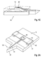
- Figure 1 shows a skin piercing element (10) which has a fluid pathway (11) which runs in an elongated portion (12,13) of the skin piercing element.
- This portion is connected to a holder (14) in form of a frame.
- the elongated portion has a protruding portion (12) which protrudes from the holder portion (14).
- a sharpened tip (15) is located at the front end of the protruding portion.
- the sharpened tip (15) enables penetration of the skin surface during pricking with the skin piercing element.
- the fluid pathway (11) starts in the front end region of the protruding portion and extends into a movable portion (13) which is located in the holder frame (14).
- the fluid pathway is an open capillary channel which permits body fluid which contacts the channel in the region of the protruding portion to move into the moveable portion (13) by means of capillary action.
- moveable portion and frame portion of the skin piercing element are formed integrally.
- the skin piercing element (10) can be made by etching processes. As well known in silicon manufacturing processes a wafer of silicon material can be etched to provide devices comprising tips and capillary channels. For mass production it is however advantageous to produce the skin piercing elements by etching of thin metal plates. It is particularly advantageous that the sharpened tip (15) of the protruding portion (12) can be formed during the etching process as well so as to avoid separate grinding steps.
- Figure 1B shows the skin piercing element (10) of figure 1A together with a fluid receiving means including a test zone.
- the fluid receiving means (40) is shown schematically.
- the fluid receiving means (40) is located on the upper side of the skin piercing element on which side the fluid channel (11) is open to the environment.
- the fluid receiving means (40) is, however, initially spaced from the fluid pathway (11) so that sample fluid within the fluid pathway does not contact the fluid receiving means. Therefore no fluid transfer from the fluid pathway onto the fluid receiving means occurs in this geometry of the fluid sampling device.
- the fluid receiving means essentially consists of a holding structure (41) which provides proper orientation and spacing of the fluid receiving means relative to the skin piercing element and a test zone (45).
- the test zone is a reagent chemistry which produces an optical signal based on the concentration of analyte in the body fluid. Due to the incorporation of porous materials as e.g. kieselguhr or titanium dioxide the reagent chemistry already has high capillarity that sucks fluid from capillary channel (11). The reagent chemistry is applied to a carrier surface. As shown in figure 1B initially the fluid pathway and the test zone (45) are spaced apart so that body fluid located in the capillary channel (11) will not be transferred to the test zone (45). After fluid has been received in the fluid pathway and has filled the moveable section (13) the body fluid sampling device is primed for measurement.
- porous materials e.g. kieselguhr or titanium dioxide
- the moveable section (13) can be bend in direction of the sensor (45) so that body fluid located in the fluid pathway contacts the test zone and wettes the reagent chemistry.
- This mode of contacting the sensor with sample fluid has several advantages over the prior art devices.
- a first advantage over the prior art is that measurement can be initiated at a specific point in time. This means that the time between wetting of the test zone and measurement of the final signal can be chosen at will. The time period, however, is shorter than the drying time of blood in the capillary. Knowing or controlling the time of reaction improves accuracy of the measurement. Further a signal can be measured beginning directly after wetting which allows to monitor reaction kinetics. Evaluation of this early signals can be used to improve accuracy of the measurement result as well.
- a further advantage can be seen from figure 1B . When the moveable section (13) is contacted with the test zone (45) it contacts an intermediate section of the fluid channel (11) but not the very end.
- the intermediate portion of the channel therefore contains fluid almost uncontaminated and without ISF. Since fluid from this region is transferred to the fluid receiving means and therefore needs to be accessible, this region is called the access region.
- This concept of transporting fluid from the capillary to the fluid receiving means serves to exclude disturbances of measurement by plasma or substances from the skin surface. It goes by its own that contamination by substances from the skin surface should be avoided if possible, in particular, when the amounts of sample for analysis are decreased to low amounts (e.g. below 1 microliter).
- this body fluid normally does not show the actual blood glucose concentration but a concentration from 5 to 30 minutes before. This is due to the time delay of exchange between the blood compartment and the interstitial fluid compartment.
- FIG 1C shows the moveable portion due to its shape in form of a tongue can be bent upwardly.
- the moveable section automatically will have enough flexibility if the skin piercing element is made from a ductile material. Suitable materials are e. g. metals, silicon and even ceramics which do not brake upon bending.
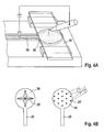
- Figure 2 shows a second embodiment where contact between the fluid channel and the fluid receiving means is accomplished by a moveable fluid receiving means.
- the skin piercing element has a protruding portion (12) with a tip (15) for piercing the skin.
- a fluid channel (11) in form of a capillary channel starts close to the piercing tip (15) and extends into an intermediate section of the holder portion (14).
- the fluid receiving means comprises a spacer (42) and a moveable carrier (43) fixed to the spacer.
- the moveable carrier (43) at its underside holds a test zone (45) in form of a reagent matrix for optical detection.
- the moveable carrier (43) When the capillary channel (11) is filled with sample fluid the moveable carrier (43) is depressed and the test zone (45) contacts the filled channel and takes up body fluid.
- the transparent carrier (43) now can be illuminated and radiation reflected by the back side of the test zone (45) can be measured to obtain a signal.
- Figure 2B shows the portion of the fluid channel (11) which contacts the sensor (45) in more detail.
- the channel has upstanding walls which protrude from the upper surface of the skin piercing element (14).
- the upstanding walls (11') have pointed edges. The function of these edges can better be seen in figure 2C which shows the interaction between test zone and fluid pathway (11).
- the left drawing of figure 2C shows the test zone (45) approaching the fluid pathway.
- the test zone (45) is located at the underside of a carrier (40).
- the body fluid (25) residing in the fluid pathway (11) has a depressed conus. This means that a slight contact between the test zone and the walls of the fluid pathway may not be sufficient to contact the body fluid with the testing material.
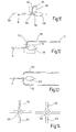
- Figure 3 depicts four embodiments showing cuts through piercing elements and test zones. This will illustrate a technical problem which has to be accounted for.
- a hydrophobic coating (16) has been applied on the body piercing element beside the fluid channel.
- contact of the test zone with the skin piercing element does not only bring the test zone and body fluid into contact but during the contact capillary spaces are generated between the test zone (or the carrier) on one hand and the portions beside the fluid pathway on the other hand.
- This normally creates a high capillarity which transfers sample fluid residing in the channel not only on the test zone but also into the small capillary spaces which are generated.
- the hydrophobic coating (16) avoids sample fluid from creeping between the upper surface of the skin piercing element (14) and the carrier or test zone. It is desired to transfer the sample onto a dedicated area of the testing material so that the transferred amounts of sample fluid are sufficient to wet the test zone in a way that an accurate measurement can be achieved. Loosing sample fluid to other regions of the test zone or to the carrier could mean that the testing material is not wetted sufficiently in the dedicated region and measurement cannot not be conducted properly.
- Figure 3B shows a further embodiment which avoids an unintentional creeping of sample fluid. Similary to figure 2 this embodiment has upstanding channel walls which contact the test zone or carrier. Due to this, fluid that creeps into spaces stops at the outer channel walls and a loss of sample fluid is largely reduced.
- the channel walls do not need to be square shaped as depicted in figure 3B but they may also be pointed as shown in figure 3C or 3D .
- Figure 4 shows the concept of electrical triggering a contact of sample fluid with the test zone.
- This general concept is shown in figure 4 with respect to a skin piercing element as special embodiment of a support structure having a channel.
- a skin piercing element for fluid triggering a high potential is applied between the sample fluid (25) and the carrier (40). This may cause either sample fluid to move from the channel onto the test zone or may cause a movement of the carrier in direction of the channel. In both cases wetting of the test zone by sample fluid can be triggered in a very short time frame by turning on the electrical potential.
- the channel beneath the test zone leads into a collecting zone (26) for providing a larger amount of fluid for wetting the test zone than the thin capillary channel would provide.
- FIG. 4B depicts preferred embodiments of collecting zones in more detail.
- the collecting zone (26) preferably has upstanding elements (26') which facilitate movement of fluid onto the test zone.
- These upstanding elements on one hand provoke high electrical charges at their end for transporting fluid and on the other hand they improve capillarity of the collecting zone (26) which improves filling with fluid.
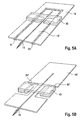
- Figures 5A , B and C depict sampler designs for providing skin piercing element and test zone in a spaced apart geometry that allows contacting of test zone with sample fluid in the channel by actuation.
- the embodiment of figure 5A is similar to Figure 1 .
- the skin piercing element comprises a frame which is connected to an inner portion (13') in which runs the capillary channel (11). Inner portion and frame are connected by bendable portions (51). After filling of the capillary channel the inner portion is torsioned against the frame so that a portion of the capillary contacts the test zone beneath the carrier (43). By bending around the bendable portions the inner portion contacts the test zone in an angled manner. This has proven to be particularly advantageous since it provides a uniform wetting of the test zone without inclusion of air bubbles.
- Figure 5B shows an embodiment where the carrier (43) and its support are connected via bendable portions (51') to a main portion (14') which comprises the capillary. Again contact between capillary and test zone is accomplished in a tilted manner.
- Figure 5C shows an embodiment having an inner portion (13 ") which is connected at two ends to the frame portion (14"). When pressure is applied from the underside to the central part of the inner portion (13") this bends against the test zone beneath the carrier (43). By bowing this inner portion again an angled contacting is achieved.
- Figure 6 schematically depicts an improved shape of the capillary channel. It has been found that the fill level of fluid in the channel generally increases with decreasing width of the capillary.
- the capillary of figure 6 has a first region (a) which leads into the tip portion of the skin piercing element.
- a second region (b) of increased diameter is for providing an increased sample volume.
- Particularly useful is third region (c) of decreased width. Due to the decreased width the fill level is increased and therefore transfer of fluid from the channel to the test zone has a high success rate. Therefore it is preferred to contact the test zone with the capillary in a tilted manner so that it first contact region (c) and thereafter region (b). This ensures that fluid transfer will be initiated safely by region (c) and enough sample for testing is provided by region (b).
- Region (d) downstream region (c) may be employed to discharge contaminated sample fluid or ISF.
- Figure 7 shows a skin piercing element having a first region (a) leading into the tip region and a second region (b) of increased diameter.
- Picture A shows a status after skin has been pierced and blood was taken into region (a) of the capillary channel. Due to lower decreased capillarity of region (b) sample liquid fills region (a) but not region (b).
- the skin piercing element is contacted with a carrier (43) the open channel structure (a, b, d) in some portion is closed at its top and capillarity is hence increased in this portion so that collection region (b) is filled and a test zone on the underside of the carrier (43) gets into contact with sample fluid. It is advantageous to have a circular detection area with view to the geometry of optical elements.
- a skin piercing element according to figure 7 may be used in following method:
- Figure 8 shows a concept where the contact between the sensor 45 and fluid pathway or channel 11 can be established by employing magnetic forces 70.
- a paramagnetic or ferromagnetic material 72 is incorporated, deposited or attached to the sensor, or to the channel portion 13.
- a current carrying wire of appropriate geometry is incorporated or attached to the sensor or the channel portion.
- a magnetic field 72 provided by an electromagnet 74 (or permanent magnet, solenoid, or other suitable means) thus exerts an actuation force 70 on the sensor (or channel portion or both), bringing them into fluidic contact.
- the force magnitude and thus the time-dependent triggering of the fluidic contact is controlled by controlling the magnetic field strength, i.e. by switching the electro magnet 74 or approaching a permanent magnet.
- a magnetic dipole moment may be induced in a nonmagnetic ring (or similar geometry) deposited on the sensor or channel portion by time-varying magnetic fields at the location of the ring. This represents an alternative way to produce an actuation force for triggered fluidic contact.
- an optical index matching element 80 is employed for coupling the test zone (sensor 45) of the fluid receiving means 82 to an optical detection unit (not shown), and, at the same time, for exerting a mechanical force to bring the fluid pathway 11 and the sensor 45 of the fluid receiving means 82 into a contacting state.
- the glucose concentration is determined by a kinetic measurement of the colour change in the sensor 45 upon wetting with a sufficiently large amount of blood contained in the pathway or channel 11.
- a reflectometric measurement is performed by illuminating the sensor 45 with incident light 84 of appropriate wavelengths and detection of the reflected radiation 86.
- the limited detection area on the sensor 45 imposes severe constraints on the mechanical positioning tolerances of the wetted test zone with regard to the optical detection system. Furthermore, if only a small detection area is available, inhomogeneities in the sensor enzyme chemistry more severely influence the coefficient of variation for repeated glucose measurements. Simultaneous optical detection of the triggered actuation between blood and sensor 45 necessitates that there no interference between the triggering actuation mechanism and the optical detection system.
- An optical system consisting of appropriate light emitter and receiver and and optics such as lenses and/or optical fibres is employed for the reflectomertric measurement.
- the amount of light of a certain wavelength reflected from the sensor 45 gives a measure of the glucose concentration.
- the sensor 45 typically consists of an enzyme chemistry mixed with small particles providing diffuse reflection of the incoming light, deposited on a polycarbonate strip or foil 82 with well defined optical transmission properties.
- the irradiating light 84 is diffusely scattered by the particles in the strip, and absorbed by dyes activated by enzymatic reactions with blood glucose.
- the amount of reflected light 86 is reduced by increased absorption with increasing glucose concentration.
- the elastomeric optical element 80 has a refractive index closely matched to that of the sensor 45.
- the element 80 is employed as an intermediate layer or slab between the sensor 45 and the optics of the detection unit.
- the element 80 may have a means 88 which allow it to be used as a lever arm for the transduction of mechanical displacement for the triggered actuation of the sensor 45 (see Figure 9 ).
- the sensor 45 on its one side abuts the element 80, whereas the opposite site of the sensor is separated by means of spacers 90 form the channel 11, keeping free an air gap 92.
- the fluid receiving means 82 Upon actuation, the fluid receiving means 82 is bend downwards and blood in the micro channel 11 underneath the sensor 42 is transferred onto the sensor, and the kinetic colour change reaction takes place.
- an optical waveguide/fibre assembly 94 in conjunction with the intermediate matching element 80 is used to illuminate the sensor 45 and collect reflected light, while the waveguide/fibre 94 simultaneously serves to displace the element 80 and hence the sensor 45 against the fluid pathway or channel 11.
- the optical waveguide/fibre 90 may also directly actuate the sensor 45, if the index matching element is provided by a special coating.
- the optical waveguide/fibre bundle 94 is mechanically actuated by an actuation mechanism (a motor, or other drive unit, or a mechanism translating the microsampler movement into a displacement of the optical waveguide/fibre).
- the intermediate elastomeric material 80 translates the mechanical displacement of the optical fibre or other mechanical actuator directly to the sensor 45, thereby serving as a mediator for the triggered actuation/contact between the sensor 45 and the adjacent portion of the blood-filled micro fluidic channel 11.
- the bundle 94 of small diameter fibres 96 is furthermore used to address small regions on the sensor 45, since the cone of acceptance of light for each single fibre 96 in the bundle is limited by its numerical aperture.
- a densely packed bundle of fibres thus serves to sample discrete small regions on the sensor.
- a few of the fibres may actually sample parts of the wetted detection area on the sensor, while other fibres sample the non-wetted parts.
- the bundle of fibres may be coupled to a detector array or CCD for individual readout of the fibres, thus generating an image of the detection area. Individual sampling of the fibres enables the detection in a small sensor area, while mechanical positioning tolerances are largely relaxed.
- Each single fibre may either be addressed for illumination of the sensor, or for collection of the diffuse reflected light, or for simultaneous illumination and collection if an appropriate beam splitter is used.
- a randomized distribution of the fibres in the bundle is desirable to provide homogeneous illumination of the sensor and complete detection coverage of the sensor surface.
- Fig. 11 shows an example for a body fluid sampling device wherein the laterally open capillary channel 11 has a sampling section 100 and a discharge section 102 branching off upstream the sampling section for taking up a fraction of the body fluid entering the capillary first at the tip region 104.
- This again allows for discharge of contaminated sample fluid or ISF, as explained above in connection to Fig. 6 .
- the capillarity of discharge section 102 is higher than the capillarity of the inlet section 106 in the region of the branching 108.
- the discharge section 102 may be closed by a lid 110. In this case, it is important to leave open a vent 112 at the end of the discharge section.
- Fig. 12 depicts an embodiment in which the discharge section is extended to comprise a waste region 114 and a reservoir region 116 upstream the waste region.
- the sampling or target section 100 is not filled during an uptake phase due to the wide opening. Only in the contact phase where the sensor 118 is brought into contact with the sampling section 100 and closes this region as a lid, the capillarity is increased and blood is sucked out of the reservoir region 116 into the sampling section 100.
- the volume of the discharge section is sufficiently large in order to be able to fill the sampling section 100 and additionally to take up the waste fluid.
- multiple discharge sections 102 can be employed.
- Different intersecting configurations 120 can be used in order to direct the fluid under capillary action ( Fig. 14 ).
- the device can further comprise a skin piercing element (10) having said fluid pathway (11).
- the fluid receiving means (40) comprises a test zone (45).
- the fluid receiving means (40) is separated from the fluid pathway (11) by an air gap (92) preferably maintained by spacers (90).
- said device is adapted to undergo a physical change upon actuation so as to assume a contacting state in which a fluid in said fluid pathway (11) contacts said fluid receiving means (40).
- said device has a moveable portion (13) which can be moved and at least a portion of said fluid pathway (11) or fluid receiving means (40) is located on said moveable portion (13) to assume the contacting state.
- said skin piercing element (10) has a fluid transfer region and at least a portion of said fluid pathway (11) in said fluid transfer region has pointed walls (11').
- said fluid receiving means (40) comprises a layer structure that can be depressed or cut by said pointed walls (11').
- body fluid received in said fluid pathway (11) is moved by electrical actuation onto the fluid receiving means (40).
- the skin piercing element (10) has a collection zone (26) in which upstanding elements (26') are located.
- the fluid pathway (11) or the fluid receiving means (40) have confining means for confining the area of fluid transfer from the fluid pathway (11) onto the fluid receiving means (40).
- said fluid pathway (11) has protruding wall portions and a surface adjacent to the fluid pathway (11) is recessed with respect to the protruding wall portions.
- a surface adjacent to the fluid pathway (11) is hydrophobic.
- said fluid receiving means (40) comprises a test zone (45) and at least one of a reaction zone, a filtration zone and a mixing zone.
- said skin-piercing element has two or more fluid pathways (11).
- said fluid pathway (11) in a first region (a) has a first width and in another region (c) has a second width which is smaller than the first width.
- said fluid pathway (11) further comprises a collecting zone (b).
- test zone (45) is located in or contacted with an intermediate portion of the fluid pathway (11) so that the fluid portion entering the pathway first is not contacted with the test zone (45).
- the fluid pathway (11) has a sampling section (100) and at least one discharge section (102) located downstream the sampling section (100) and/or branching off upstream the sampling section (100) for receiving a fraction of the body fluid entering the pathway (11) first, and wherein the sampling section (100) is a test zone (45) or can be contacted with a test zone (45) for analysis of body fluid contained therein.
- a further aspect comprises a device for sampling body fluid comprising a skin piercing element (10) with a capillary channel as a preferably laterally open fluid pathway (11) for receiving body fluid, wherein the channel has a sampling section (100) and at least one discharge section (102) located downstream the sampling section (100) and/or branching off upstream the sampling section (100) for receiving a fraction of the body fluid entering the capillary first, and wherein the sampling section (100) is a test zone (45) or can be contacted with a test zone (45) for analysis of body fluid contained therein.
- sampling section (100) is filled through an inlet section (106) of the capillary channel (11), the capillarity of the inlet section (106) being smaller than the capillarity of the at least one discharge section (102) branching off the inlet section.
- the capillarity of the discharge section (102) is increased by means of a lid (110) closing an open side portion of the discharge section (102).
- the discharge section (102) has a waste region (114) and a reservoir region (116) upstream of the waste region (114), and wherein body fluid from the reservoir region (116) is fed to the sampling section (100) after an uptake phase.
- the capillarity of the sampling section (100) is increased through contact of a fluid receiving means (40) after filling of the discharge section (102).
- volume of the discharge section (102) is larger than the volume of the sampling section (100).
- a further aspect comprises a device for body fluid analysis comprising a skin piercing element (10) with a fluid pathway (11) for receiving body fluid, wherein at least a portion of said fluid pathway (11) is open to the environment and a fluid receiving means (40) being spaced from said fluid pathway (11) so that fluid in said pathway is out of fluidic contact with the fluid receiving means (40), said fluid receiving means (40) comprising a test zone (45).
- said device comprises a meter with a detection unit for receiving signals from said test zone (45) to determine the presence and/or concentration of an analyte.
- said meter includes a holder in which said fluid receiving means (40) is received and signal transmission from the test zone (45) to the detector is enabled.
- said device comprises a contacting means which contacts a portion of the fluid pathway (11) with the fluid receiving means (40) to provide the test zone (45) with sample fluid.
- said meter has a processing unit that receives a signal indicating that the contacting means has contacted the fluid pathway (11) with the fluid receiving means (40) or that sample fluid has reached the test zone (45).
- said contacting means comprises voltage means for applying an electrical potential between said fluid pathway (11) and said fluid receiving means (40) so that fluid from the fluid pathway (11) contacts the fluid receiving means (40).
- said contacting means applies a force to a moveable portion (13) of the fluid pathway (11) or the fluid receiving means (40) to bring the fluid pathway (11) and the fluid receiving means (40) into mutual contact.
- said device comprises a magnetic contacting means (74,76) for applying a magnetic field (72) to bring the fluid pathway (11) and the fluid receiving means (40) into fluid transferring contact.
- the magnetic contacting means (74,76) includes a permanent magnet, an electromagnet (76), a solenoid or a current carrying wire.
- At least one of a paramagnetic or ferromagnetic material (74) or a current carrying element or a preferably ring-like element for producing a magnetic dipole moment under time-varying magnetic fields is incorporated or attached to a portion of the fluid pathway (11) and/or of the fluid receiving means (40).
- the contacting means has an optical matching element (80) for coupling the test zone (45) to an optical detection unit, the optical matching element (80) being adapted for exerting a mechanical force to bring the fluid pathway (11) and the fluid receiving means (40) into a contacting state.
- the optical detection unit includes a reflectometer connected to the optical matching element (80) via an optics comprising lenses, optical waveguides and/or optical fibres (94).
- optical matching element (80) is provided by a coating of the optics facing the test zone (45).
- the optical matching element (80) has a refractive index matched to the refractive index of the test zone (45).
- optical matching element (80) consists of an elastomeric material.
- optical matching element (80) is arranged on a side of the test zone (45) opposite to the fluid pathway (11) and is designed preferably as a lever arm or ram for the transduction of mechanical displacement to assume a contacting state between the fluid pathway (11) and the test zone (45).
- said device comprises a drive means for driving the skin piercing element (10) into skin to pierce the skin for obtaining a body fluid sample.
- a further aspect concerns a method for determining an analyte concentration in body fluid comprising the steps of:
- a time period beginning with step b) is monitored and determination of analyte concentration is initiated based on the time passed.
- step b) initiates a monitoring of signals and the change of signal over time is employed to determine a point in time for concentration determination.
- a further aspect concerns an analytical device comprising
- a further aspect concerns a method of sampling fluid comprising the steps of
- a further aspect concerns an analytical device comprising
- the fluid receiving means (40) comprises a test zone (45).
- the access region is an enlarged portion of the channel which forms an open chamber and in the chamber there are located upstanding elements.
- a further aspect concerns a method for transporting fluid from a support structure to a fluid receiving means (40), comprising the steps of
- a further aspect concerns a system for body fluid analysis comprising
- system further comprises a magazine storing multiple fluid receiving means (40).
- system further comprises an exposing unit for successively exposing fluid receiving means (40) from said magazine to receive fluid.
Landscapes
- Health & Medical Sciences (AREA)
- Life Sciences & Earth Sciences (AREA)
- Engineering & Computer Science (AREA)
- Physics & Mathematics (AREA)
- Medical Informatics (AREA)
- Animal Behavior & Ethology (AREA)
- Biophysics (AREA)
- Pathology (AREA)
- Biomedical Technology (AREA)
- Heart & Thoracic Surgery (AREA)
- Veterinary Medicine (AREA)
- Molecular Biology (AREA)
- Surgery (AREA)
- Public Health (AREA)
- General Health & Medical Sciences (AREA)
- Hematology (AREA)
- Manufacturing & Machinery (AREA)
- Dermatology (AREA)
- Emergency Medicine (AREA)
- Optics & Photonics (AREA)
- Measurement Of The Respiration, Hearing Ability, Form, And Blood Characteristics Of Living Organisms (AREA)
- Sampling And Sample Adjustment (AREA)
- Investigating Or Analysing Biological Materials (AREA)
Priority Applications (2)
| Application Number | Priority Date | Filing Date | Title |
|---|---|---|---|
| PL13183580T PL2705792T3 (pl) | 2004-03-06 | 2005-03-04 | Urządzenie do pobierania próbki płynu ustrojowego |
| EP13183580.3A EP2705792B1 (de) | 2004-03-06 | 2005-03-04 | Probenahmevorrichtung für Körperflüssigkeiten |
Applications Claiming Priority (3)
| Application Number | Priority Date | Filing Date | Title |
|---|---|---|---|
| EP04005385 | 2004-03-06 | ||
| EP05715716.6A EP1722670B1 (de) | 2004-03-06 | 2005-03-04 | Vorrichtung zur entnahme von körperflüssigkeit |
| EP13183580.3A EP2705792B1 (de) | 2004-03-06 | 2005-03-04 | Probenahmevorrichtung für Körperflüssigkeiten |
Related Parent Applications (1)
| Application Number | Title | Priority Date | Filing Date |
|---|---|---|---|
| EP05715716.6A Division EP1722670B1 (de) | 2004-03-06 | 2005-03-04 | Vorrichtung zur entnahme von körperflüssigkeit |
Publications (2)
| Publication Number | Publication Date |
|---|---|
| EP2705792A1 true EP2705792A1 (de) | 2014-03-12 |
| EP2705792B1 EP2705792B1 (de) | 2015-04-15 |
Family
ID=34917165
Family Applications (5)
| Application Number | Title | Priority Date | Filing Date |
|---|---|---|---|
| EP13183580.3A Active EP2705792B1 (de) | 2004-03-06 | 2005-03-04 | Probenahmevorrichtung für Körperflüssigkeiten |
| EP05715745.5A Active EP1725168B1 (de) | 2004-03-06 | 2005-03-04 | Vorrichtung zur entnahme von körperflüssigkeit |
| EP05715716.6A Active EP1722670B1 (de) | 2004-03-06 | 2005-03-04 | Vorrichtung zur entnahme von körperflüssigkeit |
| EP13004756.6A Withdrawn EP2727531A3 (de) | 2004-03-06 | 2005-03-07 | Probenahmevorrichtung für Körperflüssigkeiten |
| EP05715775.2A Active EP1725169B1 (de) | 2004-03-06 | 2005-03-07 | Vorrichtung zur entnahme von körperflüssigkeit |
Family Applications After (4)
| Application Number | Title | Priority Date | Filing Date |
|---|---|---|---|
| EP05715745.5A Active EP1725168B1 (de) | 2004-03-06 | 2005-03-04 | Vorrichtung zur entnahme von körperflüssigkeit |
| EP05715716.6A Active EP1722670B1 (de) | 2004-03-06 | 2005-03-04 | Vorrichtung zur entnahme von körperflüssigkeit |
| EP13004756.6A Withdrawn EP2727531A3 (de) | 2004-03-06 | 2005-03-07 | Probenahmevorrichtung für Körperflüssigkeiten |
| EP05715775.2A Active EP1725169B1 (de) | 2004-03-06 | 2005-03-07 | Vorrichtung zur entnahme von körperflüssigkeit |
Country Status (16)
| Country | Link |
|---|---|
| US (4) | US8000762B2 (de) |
| EP (5) | EP2705792B1 (de) |
| JP (3) | JP4917013B2 (de) |
| KR (1) | KR101198054B1 (de) |
| CN (5) | CN1929784B (de) |
| AU (2) | AU2005220022B2 (de) |
| BR (2) | BRPI0508528B8 (de) |
| CA (5) | CA2773645C (de) |
| DK (1) | DK1722670T3 (de) |
| ES (4) | ES2541680T3 (de) |
| HK (3) | HK1104439A1 (de) |
| HU (1) | HUE025706T2 (de) |
| PL (4) | PL1722670T3 (de) |
| PT (3) | PT2705792E (de) |
| SG (1) | SG153808A1 (de) |
| WO (3) | WO2005084530A2 (de) |
Families Citing this family (145)
| Publication number | Priority date | Publication date | Assignee | Title |
|---|---|---|---|---|
| US6391005B1 (en) | 1998-03-30 | 2002-05-21 | Agilent Technologies, Inc. | Apparatus and method for penetration with shaft having a sensor for sensing penetration depth |
| US8641644B2 (en) | 2000-11-21 | 2014-02-04 | Sanofi-Aventis Deutschland Gmbh | Blood testing apparatus having a rotatable cartridge with multiple lancing elements and testing means |
| AU2002315180A1 (en) | 2001-06-12 | 2002-12-23 | Pelikan Technologies, Inc. | Electric lancet actuator |
| US9226699B2 (en) | 2002-04-19 | 2016-01-05 | Sanofi-Aventis Deutschland Gmbh | Body fluid sampling module with a continuous compression tissue interface surface |
| DE60234598D1 (de) | 2001-06-12 | 2010-01-14 | Pelikan Technologies Inc | Selbstoptimierende lanzettenvorrichtung mit adaptationsmittel für zeitliche schwankungen von hauteigenschaften |
| US9427532B2 (en) | 2001-06-12 | 2016-08-30 | Sanofi-Aventis Deutschland Gmbh | Tissue penetration device |
| US7025774B2 (en) | 2001-06-12 | 2006-04-11 | Pelikan Technologies, Inc. | Tissue penetration device |
| AU2002348683A1 (en) | 2001-06-12 | 2002-12-23 | Pelikan Technologies, Inc. | Method and apparatus for lancet launching device integrated onto a blood-sampling cartridge |
| US7981056B2 (en) | 2002-04-19 | 2011-07-19 | Pelikan Technologies, Inc. | Methods and apparatus for lancet actuation |
| US8337419B2 (en) | 2002-04-19 | 2012-12-25 | Sanofi-Aventis Deutschland Gmbh | Tissue penetration device |
| US9795747B2 (en) | 2010-06-02 | 2017-10-24 | Sanofi-Aventis Deutschland Gmbh | Methods and apparatus for lancet actuation |
| US7004928B2 (en) | 2002-02-08 | 2006-02-28 | Rosedale Medical, Inc. | Autonomous, ambulatory analyte monitor or drug delivery device |
| US10022078B2 (en) | 2004-07-13 | 2018-07-17 | Dexcom, Inc. | Analyte sensor |
| US7547287B2 (en) | 2002-04-19 | 2009-06-16 | Pelikan Technologies, Inc. | Method and apparatus for penetrating tissue |
| US7297122B2 (en) | 2002-04-19 | 2007-11-20 | Pelikan Technologies, Inc. | Method and apparatus for penetrating tissue |
| US8360992B2 (en) | 2002-04-19 | 2013-01-29 | Sanofi-Aventis Deutschland Gmbh | Method and apparatus for penetrating tissue |
| US7901362B2 (en) | 2002-04-19 | 2011-03-08 | Pelikan Technologies, Inc. | Method and apparatus for penetrating tissue |
| US7909778B2 (en) | 2002-04-19 | 2011-03-22 | Pelikan Technologies, Inc. | Method and apparatus for penetrating tissue |
| US8221334B2 (en) | 2002-04-19 | 2012-07-17 | Sanofi-Aventis Deutschland Gmbh | Method and apparatus for penetrating tissue |
| US8579831B2 (en) | 2002-04-19 | 2013-11-12 | Sanofi-Aventis Deutschland Gmbh | Method and apparatus for penetrating tissue |
| US7331931B2 (en) | 2002-04-19 | 2008-02-19 | Pelikan Technologies, Inc. | Method and apparatus for penetrating tissue |
| US7229458B2 (en) | 2002-04-19 | 2007-06-12 | Pelikan Technologies, Inc. | Method and apparatus for penetrating tissue |
| US7232451B2 (en) | 2002-04-19 | 2007-06-19 | Pelikan Technologies, Inc. | Method and apparatus for penetrating tissue |
| US7976476B2 (en) | 2002-04-19 | 2011-07-12 | Pelikan Technologies, Inc. | Device and method for variable speed lancet |
| US9795334B2 (en) | 2002-04-19 | 2017-10-24 | Sanofi-Aventis Deutschland Gmbh | Method and apparatus for penetrating tissue |
| US8702624B2 (en) | 2006-09-29 | 2014-04-22 | Sanofi-Aventis Deutschland Gmbh | Analyte measurement device with a single shot actuator |
| US7491178B2 (en) | 2002-04-19 | 2009-02-17 | Pelikan Technologies, Inc. | Method and apparatus for penetrating tissue |
| US7175642B2 (en) | 2002-04-19 | 2007-02-13 | Pelikan Technologies, Inc. | Methods and apparatus for lancet actuation |
| US9314194B2 (en) | 2002-04-19 | 2016-04-19 | Sanofi-Aventis Deutschland Gmbh | Tissue penetration device |
| US8267870B2 (en) | 2002-04-19 | 2012-09-18 | Sanofi-Aventis Deutschland Gmbh | Method and apparatus for body fluid sampling with hybrid actuation |
| US8784335B2 (en) | 2002-04-19 | 2014-07-22 | Sanofi-Aventis Deutschland Gmbh | Body fluid sampling device with a capacitive sensor |
| US9248267B2 (en) | 2002-04-19 | 2016-02-02 | Sanofi-Aventis Deustchland Gmbh | Tissue penetration device |
| US7892183B2 (en) | 2002-04-19 | 2011-02-22 | Pelikan Technologies, Inc. | Method and apparatus for body fluid sampling and analyte sensing |
| US7226461B2 (en) | 2002-04-19 | 2007-06-05 | Pelikan Technologies, Inc. | Method and apparatus for a multi-use body fluid sampling device with sterility barrier release |
| US7674232B2 (en) | 2002-04-19 | 2010-03-09 | Pelikan Technologies, Inc. | Method and apparatus for penetrating tissue |
| US8372016B2 (en) | 2002-04-19 | 2013-02-12 | Sanofi-Aventis Deutschland Gmbh | Method and apparatus for body fluid sampling and analyte sensing |
| US7815579B2 (en) | 2005-03-02 | 2010-10-19 | Roche Diagnostics Operations, Inc. | Dynamic integrated lancing test strip with sterility cover |
| EP1581114B1 (de) | 2002-12-30 | 2014-04-30 | Roche Diagnostics GmbH | Flexible teststreifen-lanzettenvorrichtung |
| US8574895B2 (en) | 2002-12-30 | 2013-11-05 | Sanofi-Aventis Deutschland Gmbh | Method and apparatus using optical techniques to measure analyte levels |
| US7214200B2 (en) | 2002-12-30 | 2007-05-08 | Roche Diagnostics Operations, Inc. | Integrated analytical test element |
| US7052652B2 (en) | 2003-03-24 | 2006-05-30 | Rosedale Medical, Inc. | Analyte concentration detection devices and methods |
| EP2238892A3 (de) | 2003-05-30 | 2011-02-09 | Pelikan Technologies Inc. | Vorrichtung zur Entnahme von Körperflüssigkeit |
| WO2004107964A2 (en) | 2003-06-06 | 2004-12-16 | Pelikan Technologies, Inc. | Blood harvesting device with electronic control |
| WO2006001797A1 (en) | 2004-06-14 | 2006-01-05 | Pelikan Technologies, Inc. | Low pain penetrating |
| US7920906B2 (en) | 2005-03-10 | 2011-04-05 | Dexcom, Inc. | System and methods for processing analyte sensor data for sensor calibration |
| US8282576B2 (en) | 2003-09-29 | 2012-10-09 | Sanofi-Aventis Deutschland Gmbh | Method and apparatus for an improved sample capture device |
| EP1680014A4 (de) | 2003-10-14 | 2009-01-21 | Pelikan Technologies Inc | Verfahren und gerät für eine variable anwenderschnittstelle |
| US9247900B2 (en) | 2004-07-13 | 2016-02-02 | Dexcom, Inc. | Analyte sensor |
| WO2005065414A2 (en) | 2003-12-31 | 2005-07-21 | Pelikan Technologies, Inc. | Method and apparatus for improving fluidic flow and sample capture |
| US7822454B1 (en) | 2005-01-03 | 2010-10-26 | Pelikan Technologies, Inc. | Fluid sampling device with improved analyte detecting member configuration |
| ES2541680T3 (es) | 2004-03-06 | 2015-07-23 | F. Hoffmann-La Roche Ag | Dispositivo de muestreo de líquidos corporales |
| US7819822B2 (en) | 2004-03-06 | 2010-10-26 | Roche Diagnostics Operations, Inc. | Body fluid sampling device |
| WO2006011062A2 (en) | 2004-05-20 | 2006-02-02 | Albatros Technologies Gmbh & Co. Kg | Printable hydrogel for biosensors |
| EP1765194A4 (de) | 2004-06-03 | 2010-09-29 | Pelikan Technologies Inc | Verfahren und gerät für eine flüssigkeitsentnahmenvorrichtung |
| US9775553B2 (en) | 2004-06-03 | 2017-10-03 | Sanofi-Aventis Deutschland Gmbh | Method and apparatus for a fluid sampling device |
| US7654956B2 (en) | 2004-07-13 | 2010-02-02 | Dexcom, Inc. | Transcutaneous analyte sensor |
| US7488298B2 (en) * | 2004-10-08 | 2009-02-10 | Roche Diagnostics Operations, Inc. | Integrated lancing test strip with capillary transfer sheet |
| EP1654985A1 (de) * | 2004-11-09 | 2006-05-10 | F. Hoffmann-La Roche Ag | Probenentnahmesystem für Probenflüssigkeit |
| US8652831B2 (en) * | 2004-12-30 | 2014-02-18 | Sanofi-Aventis Deutschland Gmbh | Method and apparatus for analyte measurement test time |
| WO2006072004A2 (en) * | 2004-12-30 | 2006-07-06 | Pelikan Technologies, Inc. | Method and apparatus for analyte measurement test time |
| US20060281187A1 (en) | 2005-06-13 | 2006-12-14 | Rosedale Medical, Inc. | Analyte detection devices and methods with hematocrit/volume correction and feedback control |
| EP1759633A1 (de) * | 2005-09-01 | 2007-03-07 | F.Hoffmann-La Roche Ag | Anordnung zum Aufnehmen von Körperflüssigkeiten sowie Herstellungsverfahren hierfür |
| US8801631B2 (en) | 2005-09-30 | 2014-08-12 | Intuity Medical, Inc. | Devices and methods for facilitating fluid transport |
| EP3461406A1 (de) | 2005-09-30 | 2019-04-03 | Intuity Medical, Inc. | Kassette zur entnahme und analyse von körperflüssigkeiten mit mehreren stellen |
| CN101287406B (zh) | 2005-10-15 | 2013-04-10 | 霍夫曼-拉罗奇有限公司 | 用于对体液进行检查的测试元件 |
| EP1839576A1 (de) | 2006-03-29 | 2007-10-03 | F.Hoffmann-La Roche Ag | Testsystem mit Testeinheit zum Untersuchen von Körperflüssigkeiten |
| US20090093735A1 (en) * | 2006-03-29 | 2009-04-09 | Stephan Korner | Test unit and test system for analyzing body fluids |
| EP1878387B1 (de) | 2006-07-15 | 2010-11-24 | Roche Diagnostics GmbH | Lanzette, Lanzettenvorratsband und Stechgerät zum Erzeugen einer Einstichwunde |
| EP1878386A1 (de) | 2006-07-15 | 2008-01-16 | Roche Diagnostics GmbH | Verfahren zum Herstellen einer Lanzette, Lanzette, Lanzettenvorratsband und Stechgerät zum Erzeugen einer Einstichwunde mittels einer solchen Lanzette |
| PL1880671T3 (pl) * | 2006-07-18 | 2011-03-31 | Hoffmann La Roche | Koło lancetowe |
| EP1894526A1 (de) * | 2006-09-04 | 2008-03-05 | F. Hoffmann-la Roche AG | Lanzette |
| US8852124B2 (en) * | 2006-10-13 | 2014-10-07 | Roche Diagnostics Operations, Inc. | Tape transport lance sampler |
| DE502006003678D1 (de) | 2006-10-14 | 2009-06-18 | Roche Diagnostics Gmbh | Lanzette mit Kapillarkanal |
| EP1977686A1 (de) * | 2007-04-04 | 2008-10-08 | F.Hoffmann-La Roche Ag | Diagnostischer Einmalartikel |
| WO2008131920A2 (en) * | 2007-04-30 | 2008-11-06 | Roche Diagnostics Gmbh | Instrument and system for producing a sample of a body liquid and for analysis thereof |
| US20110092854A1 (en) | 2009-10-20 | 2011-04-21 | Uwe Kraemer | Instruments and system for producing a sample of a body fluid and for analysis thereof |
| ES2687620T3 (es) | 2007-05-04 | 2018-10-26 | Opko Diagnostics, Llc | Dispositivo y método para análisis en sistemas microfluídicos |
| WO2008145625A2 (en) | 2007-05-29 | 2008-12-04 | Roche Diagnostics Gmbh | Test system for measuring the concentration of an analyte in a body fluid |
| EP2025287A1 (de) | 2007-08-16 | 2009-02-18 | F.Hoffmann-La Roche Ag | Diagnostisches Einmalteil und Verfahren zu seiner Herstellung |
| ES2376025T3 (es) * | 2007-09-17 | 2012-03-08 | F. Hoffmann-La Roche Ag | Dispositivo de un solo uso para analizar un fluido corporal. |
| EP2205153B1 (de) * | 2007-10-08 | 2017-04-19 | Roche Diabetes Care GmbH | Analysesystem für automatischen haut-prick-test |
| EP2047798B1 (de) * | 2007-10-12 | 2010-11-17 | F. Hoffmann-La Roche AG | Testbandvorrichtung zum Untersuchen einer Körperflüssigkeit |
| KR101009447B1 (ko) * | 2007-11-12 | 2011-01-19 | 바디텍메드 주식회사 | 체액 샘플링, 전처리 및 투입장치 및 방법 |
| US7766846B2 (en) * | 2008-01-28 | 2010-08-03 | Roche Diagnostics Operations, Inc. | Rapid blood expression and sampling |
| AU2013202929B2 (en) * | 2008-01-28 | 2016-05-26 | F. Hoffmann-La Roche Ag | System for detection of an analyte in a body fluid |
| EP2087840A1 (de) | 2008-02-11 | 2009-08-12 | F.Hoffmann-La Roche Ag | Vorrichtung und Verfahren zur Körperflüssigkeitsentnahme |
| EP2093284A1 (de) | 2008-02-19 | 2009-08-26 | F.Hoffmann-La Roche Ag | Stabilisierung von Dehydrogenasen mit stabilen Coenzymen |
| WO2009105709A1 (en) | 2008-02-21 | 2009-08-27 | Dexcom, Inc. | Systems and methods for processing, transmitting and displaying sensor data |
| CN102118998B (zh) * | 2008-03-05 | 2016-02-10 | 贝克顿·迪金森公司 | 毛细管作用采集装置和容器组件 |
| WO2009126900A1 (en) | 2008-04-11 | 2009-10-15 | Pelikan Technologies, Inc. | Method and apparatus for analyte detecting device |
| JP5816080B2 (ja) | 2008-05-30 | 2015-11-17 | インテュイティ メディカル インコーポレイテッド | 体液採取装置及び採取部位インターフェイス |
| US10383556B2 (en) | 2008-06-06 | 2019-08-20 | Intuity Medical, Inc. | Medical diagnostic devices and methods |
| JP5642066B2 (ja) | 2008-06-06 | 2014-12-17 | インテュイティ メディカル インコーポレイテッド | 体液の試料内に含まれている検体の存在または濃度を決定する検定を行う方法および装置 |
| WO2010013598A1 (ja) * | 2008-08-01 | 2010-02-04 | 株式会社ライトニックス | 流路形成微細針付きセンサ |
| US8118824B2 (en) * | 2008-09-16 | 2012-02-21 | Roche Diagnostics Operations, Inc. | Magnetic powered lancing drive |
| EP2181651A1 (de) * | 2008-10-29 | 2010-05-05 | Roche Diagnostics GmbH | Instrument und System zur Herstellung einer Körperflüssigkeitsprobe und Analyse derselben |
| KR101311020B1 (ko) * | 2008-11-07 | 2013-09-25 | 에프. 호프만-라 로슈 아게 | 광도계 반응 필름용 세립 충전물질 |
| EP2208459A1 (de) | 2009-01-16 | 2010-07-21 | F. Hoffmann-Roche AG | System und Verfahren zur Analyse einer Körperflüssigkeit |
| US9375169B2 (en) | 2009-01-30 | 2016-06-28 | Sanofi-Aventis Deutschland Gmbh | Cam drive for managing disposable penetrating member actions with a single motor and motor and control system |
| TR201815133T4 (tr) | 2009-02-02 | 2018-11-21 | Opko Diagnostics Llc | Mikrofilidik cihazlar ile ışık etkileşiminin kontrol edilmesi için yapılar. |
| EP2218400A1 (de) | 2009-02-12 | 2010-08-18 | Roche Diagnostics GmbH | Lanzette mit Testbereich |
| CA2750474C (en) | 2009-02-19 | 2017-07-25 | F. Hoffmann-La Roche Ag | Fast reaction kinetics of enzymes having low activity in dry chemistry layers |
| EP2398909B1 (de) | 2009-02-19 | 2015-07-22 | F. Hoffmann-La Roche AG | Schnelle reaktionskinetik von enzymen mit niedriger aktivität in trockenen chemieschichten |
| EP2241252A1 (de) * | 2009-03-17 | 2010-10-20 | F. Hoffmann-La Roche AG | Testvorrichtung insbesondere für Blutzuckertests |
| EP2418479B1 (de) | 2009-04-07 | 2013-10-23 | Panasonic Corporation | Sensorchip sowie messvorrichtung und bluttestvorrichtung mit dem sensorchip |
| EP2263526A1 (de) | 2009-06-19 | 2010-12-22 | Roche Diagnostics GmbH | Stechsystem |
| EP2272429A1 (de) | 2009-07-10 | 2011-01-12 | Roche Diagnostics GmbH | Lanzette |
| EP2283774A1 (de) | 2009-08-13 | 2011-02-16 | Roche Diagnostics GmbH | Testelement zur Analyse einer Körperflüssigkeit |
| EP2287605A1 (de) | 2009-08-20 | 2011-02-23 | Roche Diagnostics GmbH | Vereinfachte Magazinierung integrierter Systeme |
| EP2322924A1 (de) | 2009-10-15 | 2011-05-18 | F. Hoffmann-La Roche AG | Schutz vor hydrophobierenden Agenzien |
| WO2011048200A2 (de) | 2009-10-22 | 2011-04-28 | Roche Diagnostics Gmbh | Mikrokapillarsystem mit erhöhtem probenvolumen |
| CN102068262B (zh) * | 2009-11-23 | 2012-11-21 | 财团法人金属工业研究发展中心 | 具有挠曲性按压区的采样装置 |
| CA2782047C (en) | 2009-11-30 | 2019-10-29 | Intuity Medical, Inc. | Calibration material delivery devices and methods |
| EP2333544A1 (de) | 2009-12-11 | 2011-06-15 | F. Hoffmann-La Roche AG | Sterilisierbare Chemie für Testelemente |
| JP5777633B2 (ja) | 2009-12-16 | 2015-09-09 | エフ ホフマン−ラ ロッシュ アクチェン ゲゼルシャフト | 保護された分析物の制御された放出によるテストエレメントにおける酵素の分解の検出 |
| US8965476B2 (en) | 2010-04-16 | 2015-02-24 | Sanofi-Aventis Deutschland Gmbh | Tissue penetration device |
| EP2382921A1 (de) | 2010-04-30 | 2011-11-02 | Roche Diagnostics GmbH | Stechhilfe mit automatischer Auslösung |
| US10330667B2 (en) | 2010-06-25 | 2019-06-25 | Intuity Medical, Inc. | Analyte monitoring methods and systems |
| EP2417910B1 (de) * | 2010-08-11 | 2013-06-26 | Roche Diagnostics GmbH | Analytische Testeinheit und Testsystem |
| TWI532530B (zh) * | 2010-10-29 | 2016-05-11 | 萬國商業機器公司 | 具有浸入通道之多層微流體探針頭及其製造方法 |
| TWI532468B (zh) * | 2011-03-22 | 2016-05-11 | 福 赫夫曼 拉瑞奇股份有限公司 | 具有含矽石結構奈米粒子之親水性塗層的分析輔助器具 |
| EP2520225B1 (de) | 2011-05-06 | 2014-05-21 | Roche Diagnostics GmbH | Lanzette |
| EP3407064B1 (de) * | 2011-08-03 | 2020-04-22 | Intuity Medical, Inc. | Vorrichtung zur entnahme von körperflüssigkeiten |
| JP6046724B2 (ja) * | 2011-09-23 | 2016-12-21 | エフ ホフマン−ラ ロッシュ アクチェン ゲゼルシャフト | 穿刺エレメントのマスクエッチング方法 |
| US9289763B2 (en) | 2012-07-23 | 2016-03-22 | Tasso, Inc. | Methods, systems, and devices relating to open microfluidic channels |
| BR112014021776B1 (pt) | 2012-03-05 | 2022-08-09 | Opko Diagnostics, Llc | Sistema de ensaio e método para a determinação de uma probabilidade de um evento associado com o câncer da próstata |
| BR112015005028B1 (pt) * | 2012-09-06 | 2020-12-15 | Theranos Ip Company, Llc | Sistema, dispositivos e métodos para a coleta de amostras de fluídos corporais |
| US20150320348A1 (en) * | 2012-11-16 | 2015-11-12 | Lightstat, Llc | Disposable sample collection method and apparatus |
| EP2777499B1 (de) * | 2013-03-15 | 2015-09-16 | Ortho-Clinical Diagnostics Inc | Drehbare Vorrichtung zur Flüssigkeitsprobenentnahme |
| US9523653B2 (en) | 2013-05-09 | 2016-12-20 | Changsha Sinocare Inc. | Disposable test sensor with improved sampling entrance |
| CA2912283A1 (en) | 2013-06-21 | 2014-12-21 | Intuity Medical, Inc. | Analyte monitoring system with audible feedback |
| US9518951B2 (en) | 2013-12-06 | 2016-12-13 | Changsha Sinocare Inc. | Disposable test sensor with improved sampling entrance |
| US9897566B2 (en) | 2014-01-13 | 2018-02-20 | Changsha Sinocare Inc. | Disposable test sensor |
| TWI548395B (zh) | 2014-01-28 | 2016-09-11 | 微凸科技股份有限公司 | 連續經皮微針監測系統 |
| US9939401B2 (en) | 2014-02-20 | 2018-04-10 | Changsha Sinocare Inc. | Test sensor with multiple sampling routes |
| WO2016019388A1 (en) | 2014-08-01 | 2016-02-04 | Tasso, Inc. | Devices, systems and methods for gravity-enhanced microfluidic collection, handling and transferring of fluids |
| US10779757B2 (en) * | 2014-08-01 | 2020-09-22 | Tasso, Inc. | Devices, systems and methods for gravity-enhanced microfluidic collection, handling and transferring of fluids |
| CN104874098B (zh) * | 2015-04-08 | 2018-04-10 | 上海交通大学 | 一种空心金属微针及其批量制备方法 |
| CN105738462A (zh) * | 2016-02-24 | 2016-07-06 | 长沙金域医学检验所有限公司 | 末梢血中微量元素的检测方法 |
| EP3451928B1 (de) * | 2016-05-04 | 2020-04-15 | midge medical GmbH | Vorrichtung zur entnahme von körperflüssigkeit |
| CN106137223B (zh) * | 2016-08-12 | 2019-04-26 | 上海移宇科技股份有限公司 | 一步式全集成体液采样分析仪 |
| US10596591B2 (en) * | 2017-01-04 | 2020-03-24 | Red Devil Inc. | Material dispensing system and method |
| USD967402S1 (en) * | 2019-06-05 | 2022-10-18 | Aidian Oy | Blood collecting device |
| CN111272850B (zh) * | 2019-08-20 | 2024-02-13 | 深圳硅基传感科技有限公司 | 葡萄糖传感器的工作电极 |
| CN111956237B (zh) * | 2020-07-31 | 2023-03-24 | 江苏麦酷博信息科技有限公司 | 一种rfid血样采集卡 |
Citations (18)
| Publication number | Priority date | Publication date | Assignee | Title |
|---|---|---|---|---|
| US4218421A (en) | 1978-08-18 | 1980-08-19 | Honeywell Inc. | Disposable container for a continuous band of test strips |
| EP0199484A2 (de) | 1985-04-08 | 1986-10-29 | Audio Bionics Inc | Medizinische Vorrichtung |
| EP0299517A2 (de) | 1987-07-15 | 1989-01-18 | Fuji Photo Film Co., Ltd. | Kassette für lange Teststreifen für biochemische Analysen |
| EP0723418A1 (de) | 1993-10-13 | 1996-07-31 | Integ Incorporated | Interstitielle flüssigkeitsentnahme und messung der bestandteile |
| EP0565970B1 (de) | 1992-04-13 | 1997-09-24 | Boehringer Mannheim Gmbh | Blutlanzettenvorrichtung zur Entnahme von Blut für Diagnosezwecke |
| WO1997042888A1 (en) | 1996-05-17 | 1997-11-20 | Mercury Diagnostics Inc. | Blood and interstitial fluid sampling device |
| US5762770A (en) | 1994-02-21 | 1998-06-09 | Boehringer Mannheim Corporation | Electrochemical biosensor test strip |
| US5801057A (en) | 1996-03-22 | 1998-09-01 | Smart; Wilson H. | Microsampling device and method of construction |
| USRE36268E (en) | 1988-03-15 | 1999-08-17 | Boehringer Mannheim Corporation | Method and apparatus for amperometric diagnostic analysis |
| WO2001072220A1 (en) * | 2000-03-27 | 2001-10-04 | Usf Filtration And Separations Group, Inc. | Method and device for sampling and analyzing interstitial fluid and whole blood samples |
| WO2001091634A2 (en) * | 2000-05-26 | 2001-12-06 | Abbott Laboratories | Apparatus and method for obtaining blood for diagnostic tests |
| US6379317B1 (en) * | 1997-11-28 | 2002-04-30 | Hans Kintzig | Analytical measuring device with lancing device |
| US20020168290A1 (en) | 2002-05-09 | 2002-11-14 | Yuzhakov Vadim V. | Physiological sample collection devices and methods of using the same |
| WO2002100253A2 (en) * | 2001-06-12 | 2002-12-19 | Pelikan Technologies, Inc. | Blood sampling device with diaphragm actuated lancet |
| US20030018282A1 (en) | 2001-07-20 | 2003-01-23 | Carlo Effenhauser | System for withdrawing small amounts of body fluid |
| US20030028125A1 (en) | 2001-08-06 | 2003-02-06 | Yuzhakov Vadim V. | Physiological sample collection devices and methods of using the same |
| US20030212424A1 (en) * | 2002-04-19 | 2003-11-13 | Pelikan Technologies, Inc. | Method and apparatus for lancet actuation |
| EP1371419A1 (de) * | 2002-06-12 | 2003-12-17 | F. Hoffmann-La Roche AG | Verfahren und Vorrichtung zur Detektion eines Analyten in einer Probe |
Family Cites Families (79)
| Publication number | Priority date | Publication date | Assignee | Title |
|---|---|---|---|---|
| US6268A (en) * | 1849-04-03 | James h | ||
| US2728343A (en) | 1954-06-03 | 1955-12-27 | S & R J Everett & Co Ltd | Sewing needles |
| SE388280B (sv) | 1972-04-28 | 1976-09-27 | Harco Electr Ltd | Apparat for kvantitetsmetning av fluidum i provremsor |
| US4935346A (en) | 1986-08-13 | 1990-06-19 | Lifescan, Inc. | Minimum procedure system for the determination of analytes |
| US5108889A (en) * | 1988-10-12 | 1992-04-28 | Thorne, Smith, Astill Technologies, Inc. | Assay for determining analyte using mercury release followed by detection via interaction with aluminum |
| JPH0810207B2 (ja) * | 1989-11-08 | 1996-01-31 | 日本特殊陶業株式会社 | バイオセンサ |
| US5172701A (en) | 1990-02-28 | 1992-12-22 | Medical Device Technologies, Inc. | Single use automated soft tissue aspiration biopsy device |
| US5055203A (en) * | 1990-05-22 | 1991-10-08 | Eastman Kodak Company | Blood collection device with reduced serum dispensing volume and integral needle |
| US5163442A (en) * | 1991-07-30 | 1992-11-17 | Harry Ono | Finger tip blood collector |
| US5318514A (en) | 1992-08-17 | 1994-06-07 | Btx, Inc. | Applicator for the electroporation of drugs and genes into surface cells |
| US5591139A (en) * | 1994-06-06 | 1997-01-07 | The Regents Of The University Of California | IC-processed microneedles |
| US5644177A (en) | 1995-02-23 | 1997-07-01 | Wisconsin Alumni Research Foundation | Micromechanical magnetically actuated devices |
| WO1997018036A1 (en) | 1995-11-13 | 1997-05-22 | Cortecs (Uk) Limited | Diagnostic test apparatus |
| CN1207056A (zh) * | 1995-11-13 | 1999-02-03 | 科特克斯(英国)有限公司 | 诊断试验设备 |
| DK0921840T3 (da) | 1996-07-03 | 2003-09-22 | Altea Therapeutics Corp | Multipel mekanisk mikroperforering af hud eller slimhinde |
| US6486947B2 (en) | 1998-07-22 | 2002-11-26 | Ljl Biosystems, Inc. | Devices and methods for sample analysis |
| US5931794A (en) | 1997-10-21 | 1999-08-03 | Pitesky; Isadore | Allergy testing apparatus |
| US6063040A (en) * | 1998-01-16 | 2000-05-16 | Specialized Health Products, Inc. | Self retracting needle apparatus and method for phlebotomy |
| CZ296644B6 (cs) | 1998-04-24 | 2006-05-17 | Roche Diagnostics Gmbh | Úlozná schránka pro vyuzití v kompaktním mericím prístroji a zarízení pro ulození analytických prípravku |
| US6214030B1 (en) | 1998-08-10 | 2001-04-10 | Mani, Inc. | Suture needle |
| US6660018B2 (en) | 1999-03-08 | 2003-12-09 | Agilent Technologies, Inc. | Multiple lancet device |
| US6132449A (en) * | 1999-03-08 | 2000-10-17 | Agilent Technologies, Inc. | Extraction and transportation of blood for analysis |
| US6368563B1 (en) * | 1999-03-12 | 2002-04-09 | Integ, Inc. | Collection well for body fluid tester |
| US6252195B1 (en) | 1999-04-26 | 2001-06-26 | Ethicon, Inc. | Method of forming blind holes in surgical needles using a diode pumped Nd-YAG laser |
| EP1078602A3 (de) | 1999-08-26 | 2001-04-04 | Mani, Inc. | Nähnadel zu einem medizinischen Zweck |
| US6364889B1 (en) | 1999-11-17 | 2002-04-02 | Bayer Corporation | Electronic lancing device |
| US7499745B2 (en) | 2000-02-28 | 2009-03-03 | Barbara Ann Karmanos Cancer Institute | Multidimensional bioelectrical tissue analyzer |
| CA2399842C (en) | 2000-03-02 | 2006-11-14 | Microchips, Inc. | Microfabricated devices for the storage and selective exposure of chemicals and devices |
| DE10010694A1 (de) | 2000-03-04 | 2001-09-06 | Roche Diagnostics Gmbh | Blutlanzette mit hygienischen Spitzenschutz |
| DE10026172A1 (de) | 2000-05-26 | 2001-11-29 | Roche Diagnostics Gmbh | System zur Entnahme von Körperflüssigkeit |
| WO2001093930A1 (en) | 2000-06-02 | 2001-12-13 | The University Of Utah Research Foundation | Active needle devices with integrated functionality |
| US6540675B2 (en) | 2000-06-27 | 2003-04-01 | Rosedale Medical, Inc. | Analyte monitor |
| AU2001280796A1 (en) | 2000-07-25 | 2002-02-05 | The Regents Of The University Of California | Electrowetting-driven micropumping |
| US6773566B2 (en) | 2000-08-31 | 2004-08-10 | Nanolytics, Inc. | Electrostatic actuators for microfluidics and methods for using same |
| EP1203563A3 (de) | 2000-10-31 | 2004-01-02 | Boehringer Mannheim Gmbh | Analytisches Hilfsmittel mit integrierter Lanzette |
| EP1331997B1 (de) | 2000-11-06 | 2004-06-16 | Nanostream, Inc. | Mikrofluidische durchflussregelvorrichtung |
| US6638246B1 (en) | 2000-11-28 | 2003-10-28 | Scimed Life Systems, Inc. | Medical device for delivery of a biologically active material to a lumen |
| WO2002064193A2 (en) | 2000-12-14 | 2002-08-22 | Georgia Tech Research Corporation | Microneedle devices and production thereof |
| GB0030929D0 (en) * | 2000-12-19 | 2001-01-31 | Inverness Medical Ltd | Analyte measurement |
| DE10105549A1 (de) * | 2001-02-06 | 2002-08-29 | Roche Diagnostics Gmbh | System zur Überwachung der Konzentration von Analyten in Körperflüssigkeiten |
| KR100398309B1 (ko) | 2001-02-20 | 2003-09-19 | 한국과학기술원 | 연속 전기습윤에 의해 유도된 운동하는 액체 방울에 의해구동되는 마이크로펌프 |
| JP3845413B2 (ja) * | 2001-06-08 | 2006-11-15 | エフ ホフマン−ラ ロッシュ アクチェン ゲゼルシャフト | 体液サンプリング装置およびこのような装置とともに使用される試験媒体カセット |
| US6837988B2 (en) | 2001-06-12 | 2005-01-04 | Lifescan, Inc. | Biological fluid sampling and analyte measurement devices and methods |
| US6793632B2 (en) | 2001-06-12 | 2004-09-21 | Lifescan, Inc. | Percutaneous biological fluid constituent sampling and measurement devices and methods |
| US7025774B2 (en) * | 2001-06-12 | 2006-04-11 | Pelikan Technologies, Inc. | Tissue penetration device |
| US6875613B2 (en) | 2001-06-12 | 2005-04-05 | Lifescan, Inc. | Biological fluid constituent sampling and measurement devices and methods |
| US20030028087A1 (en) | 2001-08-01 | 2003-02-06 | Yuzhakov Vadim Vladimirovich | Devices for analyte concentration determination and methods of using the same |
| SE0102736D0 (sv) | 2001-08-14 | 2001-08-14 | Patrick Griss | Side opened out-of-plane microneedles for microfluidic transdermal interfacing and fabrication process of side opened out-of-plane microneedles |
| US6966880B2 (en) * | 2001-10-16 | 2005-11-22 | Agilent Technologies, Inc. | Universal diagnostic platform |
| WO2003049631A1 (en) | 2001-12-12 | 2003-06-19 | Tissuelink Medical, Inc. | Fluid-assisted medical devices, systems and methods |
| US6840909B2 (en) | 2002-03-25 | 2005-01-11 | Acueity, Inc. | Apparatus and method for intraductal cytology |
| US7343188B2 (en) | 2002-05-09 | 2008-03-11 | Lifescan, Inc. | Devices and methods for accessing and analyzing physiological fluid |
| US20030212344A1 (en) | 2002-05-09 | 2003-11-13 | Vadim Yuzhakov | Physiological sample collection devices and methods of using the same |
| AU2003239926A1 (en) | 2002-05-31 | 2003-12-19 | Facet Technologies, Llc | Precisely guided lancet |
| US20030223906A1 (en) | 2002-06-03 | 2003-12-04 | Mcallister Devin | Test strip container system |
| US7740595B2 (en) | 2002-07-26 | 2010-06-22 | Stuart Brown | Tissue and fluid sampling device |
| US7241420B2 (en) | 2002-08-05 | 2007-07-10 | Palo Alto Research Center Incorporated | Capillary-channel probes for liquid pickup, transportation and dispense using stressy metal |
| US8062573B2 (en) | 2002-09-16 | 2011-11-22 | Theraject, Inc. | Solid micro-perforators and methods of use |
| US6989234B2 (en) * | 2002-09-24 | 2006-01-24 | Duke University | Method and apparatus for non-contact electrostatic actuation of droplets |
| US7192405B2 (en) | 2002-09-30 | 2007-03-20 | Becton, Dickinson And Company | Integrated lancet and bodily fluid sensor |
| EP1424040A1 (de) | 2002-11-26 | 2004-06-02 | Roche Diagnostics GmbH | Vorrichtung zur Untersuchung von Körperflüssigkeiten |
| US20040193072A1 (en) * | 2003-03-28 | 2004-09-30 | Allen John J. | Method of analyte measurement using integrated lance and strip |
| US7604592B2 (en) | 2003-06-13 | 2009-10-20 | Pelikan Technologies, Inc. | Method and apparatus for a point of care device |
| DE10327683A1 (de) | 2003-06-20 | 2005-01-20 | Bayer Technology Services Gmbh | Verfahren und Vorrichtung zum quantitativen elektrischen Nachweis von Analyten |
| US20050043597A1 (en) | 2003-07-31 | 2005-02-24 | Skymoon Research And Development, Llc | Optical vivo probe of analyte concentration within the sterile matrix under the human nail |
| US7223248B2 (en) | 2003-08-13 | 2007-05-29 | Lifescan, Inc. | Packaged medical device with a deployable dermal tissue penetration member |
| US7361182B2 (en) | 2003-12-19 | 2008-04-22 | Lightnix, Inc. | Medical lancet |
| US7410590B2 (en) | 2003-12-19 | 2008-08-12 | Palo Alto Research Center Incorporated | Transferable micro spring structure |
| ES2541680T3 (es) | 2004-03-06 | 2015-07-23 | F. Hoffmann-La Roche Ag | Dispositivo de muestreo de líquidos corporales |
| US7819822B2 (en) | 2004-03-06 | 2010-10-26 | Roche Diagnostics Operations, Inc. | Body fluid sampling device |
| US7351213B2 (en) | 2004-04-15 | 2008-04-01 | Roche Diagnostics Operation, Inc. | Integrated spot monitoring device with fluid sensor |
| WO2006014686A2 (en) | 2004-07-20 | 2006-02-09 | Bayer Healthcare Llc | Multiple tip lancet |
| US20060047309A1 (en) | 2004-08-25 | 2006-03-02 | Cichocki Frank R Jr | Metal injection molded suture needles |
| JP2006119401A (ja) | 2004-10-22 | 2006-05-11 | Seiko Epson Corp | 電気光学装置の製造方法及び製造装置、電気光学装置並びに電子機器 |
| US7771803B2 (en) | 2004-10-27 | 2010-08-10 | Palo Alto Research Center Incorporated | Oblique parts or surfaces |
| US20070270738A1 (en) | 2005-04-25 | 2007-11-22 | Wu Jeffrey M | Method of treating ACNE with stratum corneum piercing patch |
| EP3461406A1 (de) | 2005-09-30 | 2019-04-03 | Intuity Medical, Inc. | Kassette zur entnahme und analyse von körperflüssigkeiten mit mehreren stellen |
| US7453339B2 (en) | 2005-12-02 | 2008-11-18 | Palo Alto Research Center Incorporated | Electromechanical switch |
| US7766846B2 (en) | 2008-01-28 | 2010-08-03 | Roche Diagnostics Operations, Inc. | Rapid blood expression and sampling |
-
2005
- 2005-03-04 ES ES13183580.3T patent/ES2541680T3/es active Active
- 2005-03-04 CN CN200580007255XA patent/CN1929784B/zh not_active Expired - Fee Related
- 2005-03-04 PT PT131835803T patent/PT2705792E/pt unknown
- 2005-03-04 PT PT57157166T patent/PT1722670E/pt unknown
- 2005-03-04 KR KR1020067016887A patent/KR101198054B1/ko active IP Right Grant
- 2005-03-04 CN CN2009101795128A patent/CN101690665B/zh not_active Expired - Fee Related
- 2005-03-04 PL PL05715716T patent/PL1722670T3/pl unknown
- 2005-03-04 ES ES05715716.6T patent/ES2438215T3/es active Active
- 2005-03-04 PL PL13183580T patent/PL2705792T3/pl unknown
- 2005-03-04 EP EP13183580.3A patent/EP2705792B1/de active Active
- 2005-03-04 HU HUE13183580A patent/HUE025706T2/en unknown
- 2005-03-04 ES ES05715745.5T patent/ES2572775T3/es active Active
- 2005-03-04 CA CA2773645A patent/CA2773645C/en not_active Expired - Fee Related
- 2005-03-04 WO PCT/EP2005/002273 patent/WO2005084530A2/en active Application Filing
- 2005-03-04 JP JP2007501224A patent/JP4917013B2/ja not_active Expired - Fee Related
- 2005-03-04 JP JP2007501232A patent/JP4602398B2/ja not_active Expired - Fee Related
- 2005-03-04 PL PL05715745.5T patent/PL1725168T3/pl unknown
- 2005-03-04 WO PCT/EP2005/002316 patent/WO2005084545A1/en not_active Application Discontinuation
- 2005-03-04 EP EP05715745.5A patent/EP1725168B1/de active Active
- 2005-03-04 AU AU2005220022A patent/AU2005220022B2/en active Active
- 2005-03-04 EP EP05715716.6A patent/EP1722670B1/de active Active
- 2005-03-04 CA CA2557966A patent/CA2557966C/en not_active Expired - Fee Related
- 2005-03-04 BR BRPI0508528A patent/BRPI0508528B8/pt not_active IP Right Cessation
- 2005-03-04 DK DK05715716.6T patent/DK1722670T3/da active
- 2005-03-04 CN CNB2005800072564A patent/CN100563561C/zh not_active Expired - Fee Related
- 2005-03-04 CA CA2558086A patent/CA2558086C/en not_active Expired - Fee Related
- 2005-03-07 EP EP13004756.6A patent/EP2727531A3/de not_active Withdrawn
- 2005-03-07 CN CN201310004560.XA patent/CN103126689B/zh not_active Expired - Fee Related
- 2005-03-07 CA CA2558121A patent/CA2558121C/en not_active Expired - Fee Related
- 2005-03-07 PL PL05715775T patent/PL1725169T3/pl unknown
- 2005-03-07 ES ES05715775.2T patent/ES2470979T3/es active Active
- 2005-03-07 CA CA2837991A patent/CA2837991C/en not_active Expired - Fee Related
- 2005-03-07 BR BRPI0508515A patent/BRPI0508515B8/pt not_active IP Right Cessation
- 2005-03-07 CN CNA2005800072545A patent/CN1929783A/zh active Pending
- 2005-03-07 EP EP05715775.2A patent/EP1725169B1/de active Active
- 2005-03-07 WO PCT/EP2005/002357 patent/WO2005084546A2/en not_active Application Discontinuation
- 2005-03-07 AU AU2005220027A patent/AU2005220027B2/en active Active
- 2005-03-07 PT PT57157752T patent/PT1725169E/pt unknown
- 2005-03-07 JP JP2007501237A patent/JP4959545B2/ja not_active Expired - Fee Related
- 2005-03-07 SG SG200903875-3A patent/SG153808A1/en unknown
-
2006
- 2006-08-31 US US11/469,123 patent/US8000762B2/en not_active Expired - Fee Related
- 2006-09-05 US US11/470,021 patent/US8162854B2/en active Active
-
2007
- 2007-09-05 HK HK07109666.7A patent/HK1104439A1/xx not_active IP Right Cessation
- 2007-10-15 HK HK07111095.4A patent/HK1105847A1/xx not_active IP Right Cessation
-
2010
- 2010-09-28 HK HK10109266.6A patent/HK1142790A1/xx not_active IP Right Cessation
-
2011
- 2011-06-23 US US13/167,243 patent/US8369918B2/en active Active
-
2012
- 2012-03-15 US US13/421,163 patent/US9022952B2/en active Active
Patent Citations (19)
| Publication number | Priority date | Publication date | Assignee | Title |
|---|---|---|---|---|
| US4218421A (en) | 1978-08-18 | 1980-08-19 | Honeywell Inc. | Disposable container for a continuous band of test strips |
| EP0199484A2 (de) | 1985-04-08 | 1986-10-29 | Audio Bionics Inc | Medizinische Vorrichtung |
| EP0299517A2 (de) | 1987-07-15 | 1989-01-18 | Fuji Photo Film Co., Ltd. | Kassette für lange Teststreifen für biochemische Analysen |
| USRE36268E (en) | 1988-03-15 | 1999-08-17 | Boehringer Mannheim Corporation | Method and apparatus for amperometric diagnostic analysis |
| EP0565970B1 (de) | 1992-04-13 | 1997-09-24 | Boehringer Mannheim Gmbh | Blutlanzettenvorrichtung zur Entnahme von Blut für Diagnosezwecke |
| EP0723418A1 (de) | 1993-10-13 | 1996-07-31 | Integ Incorporated | Interstitielle flüssigkeitsentnahme und messung der bestandteile |
| US5762770A (en) | 1994-02-21 | 1998-06-09 | Boehringer Mannheim Corporation | Electrochemical biosensor test strip |
| US5801057A (en) | 1996-03-22 | 1998-09-01 | Smart; Wilson H. | Microsampling device and method of construction |
| WO1997042888A1 (en) | 1996-05-17 | 1997-11-20 | Mercury Diagnostics Inc. | Blood and interstitial fluid sampling device |
| US6379317B1 (en) * | 1997-11-28 | 2002-04-30 | Hans Kintzig | Analytical measuring device with lancing device |
| WO2001072220A1 (en) * | 2000-03-27 | 2001-10-04 | Usf Filtration And Separations Group, Inc. | Method and device for sampling and analyzing interstitial fluid and whole blood samples |
| WO2001091634A2 (en) * | 2000-05-26 | 2001-12-06 | Abbott Laboratories | Apparatus and method for obtaining blood for diagnostic tests |
| WO2002100253A2 (en) * | 2001-06-12 | 2002-12-19 | Pelikan Technologies, Inc. | Blood sampling device with diaphragm actuated lancet |
| US20030018282A1 (en) | 2001-07-20 | 2003-01-23 | Carlo Effenhauser | System for withdrawing small amounts of body fluid |
| US20030028125A1 (en) | 2001-08-06 | 2003-02-06 | Yuzhakov Vadim V. | Physiological sample collection devices and methods of using the same |
| EP1284121A2 (de) * | 2001-08-06 | 2003-02-19 | Lifescan, Inc. | Vorrichtungen und Verfahren zur Probeentnahme |
| US20030212424A1 (en) * | 2002-04-19 | 2003-11-13 | Pelikan Technologies, Inc. | Method and apparatus for lancet actuation |
| US20020168290A1 (en) | 2002-05-09 | 2002-11-14 | Yuzhakov Vadim V. | Physiological sample collection devices and methods of using the same |
| EP1371419A1 (de) * | 2002-06-12 | 2003-12-17 | F. Hoffmann-La Roche AG | Verfahren und Vorrichtung zur Detektion eines Analyten in einer Probe |
Also Published As
Similar Documents
| Publication | Publication Date | Title |
|---|---|---|
| EP2705792B1 (de) | Probenahmevorrichtung für Körperflüssigkeiten | |
| US8814808B2 (en) | Body fluid sampling device | |
| MXPA06009307A (en) | Body fluid sampling device |
Legal Events
| Date | Code | Title | Description |
|---|---|---|---|
| PUAI | Public reference made under article 153(3) epc to a published international application that has entered the european phase |
Free format text: ORIGINAL CODE: 0009012 |
|
| AC | Divisional application: reference to earlier application |
Ref document number: 1722670 Country of ref document: EP Kind code of ref document: P |
|
| AK | Designated contracting states |
Kind code of ref document: A1 Designated state(s): AT BE BG CH CY CZ DE DK EE ES FI FR GB GR HU IE IS IT LI LT LU MC NL PL PT RO SE SI SK TR |
|
| 17P | Request for examination filed |
Effective date: 20140908 |
|
| RBV | Designated contracting states (corrected) |
Designated state(s): AT BE BG CH CY CZ DE DK EE ES FI FR GB GR HU IE IS IT LI LT LU MC NL PL PT RO SE SI SK TR |
|
| GRAP | Despatch of communication of intention to grant a patent |
Free format text: ORIGINAL CODE: EPIDOSNIGR1 |
|
| RIC1 | Information provided on ipc code assigned before grant |
Ipc: A61B 5/15 20060101AFI20141013BHEP Ipc: A61B 5/1486 20060101ALN20141013BHEP Ipc: A61B 5/145 20060101ALN20141013BHEP |
|
| INTG | Intention to grant announced |
Effective date: 20141113 |
|
| GRAS | Grant fee paid |
Free format text: ORIGINAL CODE: EPIDOSNIGR3 |
|
| GRAA | (expected) grant |
Free format text: ORIGINAL CODE: 0009210 |
|
| AC | Divisional application: reference to earlier application |
Ref document number: 1722670 Country of ref document: EP Kind code of ref document: P |
|
| AK | Designated contracting states |
Kind code of ref document: B1 Designated state(s): AT BE BG CH CY CZ DE DK EE ES FI FR GB GR HU IE IS IT LI LT LU MC NL PL PT RO SE SI SK TR |
|
| REG | Reference to a national code |
Ref country code: GB Ref legal event code: FG4D Ref country code: CH Ref legal event code: EP |
|
| REG | Reference to a national code |
Ref country code: IE Ref legal event code: FG4D |
|
| REG | Reference to a national code |
Ref country code: AT Ref legal event code: REF Ref document number: 721484 Country of ref document: AT Kind code of ref document: T Effective date: 20150515 |
|
| REG | Reference to a national code |
Ref country code: DE Ref legal event code: R096 Ref document number: 602005046377 Country of ref document: DE Effective date: 20150528 |
|
| REG | Reference to a national code |
Ref country code: PT Ref legal event code: SC4A Free format text: AVAILABILITY OF NATIONAL TRANSLATION Effective date: 20150529 |
|
| REG | Reference to a national code |
Ref country code: ES Ref legal event code: FG2A Ref document number: 2541680 Country of ref document: ES Kind code of ref document: T3 Effective date: 20150723 |
|
| REG | Reference to a national code |
Ref country code: LT Ref legal event code: MG4D |
|
| PG25 | Lapsed in a contracting state [announced via postgrant information from national office to epo] |
Ref country code: FI Free format text: LAPSE BECAUSE OF FAILURE TO SUBMIT A TRANSLATION OF THE DESCRIPTION OR TO PAY THE FEE WITHIN THE PRESCRIBED TIME-LIMIT Effective date: 20150415 Ref country code: LT Free format text: LAPSE BECAUSE OF FAILURE TO SUBMIT A TRANSLATION OF THE DESCRIPTION OR TO PAY THE FEE WITHIN THE PRESCRIBED TIME-LIMIT Effective date: 20150415 |
|
| REG | Reference to a national code |
Ref country code: PL Ref legal event code: T3 |
|
| PG25 | Lapsed in a contracting state [announced via postgrant information from national office to epo] |
Ref country code: IS Free format text: LAPSE BECAUSE OF FAILURE TO SUBMIT A TRANSLATION OF THE DESCRIPTION OR TO PAY THE FEE WITHIN THE PRESCRIBED TIME-LIMIT Effective date: 20150815 Ref country code: GR Free format text: LAPSE BECAUSE OF FAILURE TO SUBMIT A TRANSLATION OF THE DESCRIPTION OR TO PAY THE FEE WITHIN THE PRESCRIBED TIME-LIMIT Effective date: 20150716 |
|
| REG | Reference to a national code |
Ref country code: DE Ref legal event code: R097 Ref document number: 602005046377 Country of ref document: DE |
|
| PG25 | Lapsed in a contracting state [announced via postgrant information from national office to epo] |
Ref country code: EE Free format text: LAPSE BECAUSE OF FAILURE TO SUBMIT A TRANSLATION OF THE DESCRIPTION OR TO PAY THE FEE WITHIN THE PRESCRIBED TIME-LIMIT Effective date: 20150415 Ref country code: DK Free format text: LAPSE BECAUSE OF FAILURE TO SUBMIT A TRANSLATION OF THE DESCRIPTION OR TO PAY THE FEE WITHIN THE PRESCRIBED TIME-LIMIT Effective date: 20150415 |
|
| PLBE | No opposition filed within time limit |
Free format text: ORIGINAL CODE: 0009261 |
|
| STAA | Information on the status of an ep patent application or granted ep patent |
Free format text: STATUS: NO OPPOSITION FILED WITHIN TIME LIMIT |
|
| REG | Reference to a national code |
Ref country code: FR Ref legal event code: PLFP Year of fee payment: 12 |
|
| PG25 | Lapsed in a contracting state [announced via postgrant information from national office to epo] |
Ref country code: SK Free format text: LAPSE BECAUSE OF FAILURE TO SUBMIT A TRANSLATION OF THE DESCRIPTION OR TO PAY THE FEE WITHIN THE PRESCRIBED TIME-LIMIT Effective date: 20150415 Ref country code: RO Free format text: LAPSE BECAUSE OF NON-PAYMENT OF DUE FEES Effective date: 20150415 |
|
| 26N | No opposition filed |
Effective date: 20160118 |
|
| REG | Reference to a national code |
Ref country code: DE Ref legal event code: R082 Ref document number: 602005046377 Country of ref document: DE Representative=s name: WOLF, PFIZ & GAUSS PATENTANWAELTE PARTNERSCHAF, DE Ref country code: DE Ref legal event code: R081 Ref document number: 602005046377 Country of ref document: DE Owner name: ROCHE DIABETES CARE GMBH, DE Free format text: FORMER OWNER: ROCHE DIAGNOSTICS GMBH, 68305 MANNHEIM, DE Ref country code: DE Ref legal event code: R082 Ref document number: 602005046377 Country of ref document: DE Representative=s name: PFIZ/GAUSS PATENTANWAELTE PARTMBB, DE |
|
| REG | Reference to a national code |
Ref country code: HU Ref legal event code: AG4A Ref document number: E025706 Country of ref document: HU |
|
| PG25 | Lapsed in a contracting state [announced via postgrant information from national office to epo] |
Ref country code: SI Free format text: LAPSE BECAUSE OF FAILURE TO SUBMIT A TRANSLATION OF THE DESCRIPTION OR TO PAY THE FEE WITHIN THE PRESCRIBED TIME-LIMIT Effective date: 20150415 |
|
| PG25 | Lapsed in a contracting state [announced via postgrant information from national office to epo] |
Ref country code: BE Free format text: LAPSE BECAUSE OF FAILURE TO SUBMIT A TRANSLATION OF THE DESCRIPTION OR TO PAY THE FEE WITHIN THE PRESCRIBED TIME-LIMIT Effective date: 20150415 |
|
| PG25 | Lapsed in a contracting state [announced via postgrant information from national office to epo] |
Ref country code: LU Free format text: LAPSE BECAUSE OF FAILURE TO SUBMIT A TRANSLATION OF THE DESCRIPTION OR TO PAY THE FEE WITHIN THE PRESCRIBED TIME-LIMIT Effective date: 20160304 Ref country code: MC Free format text: LAPSE BECAUSE OF FAILURE TO SUBMIT A TRANSLATION OF THE DESCRIPTION OR TO PAY THE FEE WITHIN THE PRESCRIBED TIME-LIMIT Effective date: 20150415 |
|
| REG | Reference to a national code |
Ref country code: FR Ref legal event code: PLFP Year of fee payment: 13 |
|
| REG | Reference to a national code |
Ref country code: AT Ref legal event code: UEP Ref document number: 721484 Country of ref document: AT Kind code of ref document: T Effective date: 20150415 |
|
| PG25 | Lapsed in a contracting state [announced via postgrant information from national office to epo] |
Ref country code: SE Free format text: LAPSE BECAUSE OF FAILURE TO SUBMIT A TRANSLATION OF THE DESCRIPTION OR TO PAY THE FEE WITHIN THE PRESCRIBED TIME-LIMIT Effective date: 20150415 |
|
| REG | Reference to a national code |
Ref country code: FR Ref legal event code: PLFP Year of fee payment: 14 |
|
| PG25 | Lapsed in a contracting state [announced via postgrant information from national office to epo] |
Ref country code: CY Free format text: LAPSE BECAUSE OF FAILURE TO SUBMIT A TRANSLATION OF THE DESCRIPTION OR TO PAY THE FEE WITHIN THE PRESCRIBED TIME-LIMIT Effective date: 20150415 |
|
| PG25 | Lapsed in a contracting state [announced via postgrant information from national office to epo] |
Ref country code: BG Free format text: LAPSE BECAUSE OF FAILURE TO SUBMIT A TRANSLATION OF THE DESCRIPTION OR TO PAY THE FEE WITHIN THE PRESCRIBED TIME-LIMIT Effective date: 20150415 |
|
| PGFP | Annual fee paid to national office [announced via postgrant information from national office to epo] |
Ref country code: PL Payment date: 20201223 Year of fee payment: 17 |
|
| PGFP | Annual fee paid to national office [announced via postgrant information from national office to epo] |
Ref country code: PT Payment date: 20210223 Year of fee payment: 17 Ref country code: NL Payment date: 20210212 Year of fee payment: 17 Ref country code: IT Payment date: 20210316 Year of fee payment: 17 Ref country code: IE Payment date: 20210223 Year of fee payment: 17 Ref country code: CH Payment date: 20210210 Year of fee payment: 17 Ref country code: CZ Payment date: 20210212 Year of fee payment: 17 Ref country code: FR Payment date: 20210219 Year of fee payment: 17 |
|
| PGFP | Annual fee paid to national office [announced via postgrant information from national office to epo] |
Ref country code: DE Payment date: 20210210 Year of fee payment: 17 Ref country code: AT Payment date: 20210223 Year of fee payment: 17 Ref country code: GB Payment date: 20210311 Year of fee payment: 17 Ref country code: HU Payment date: 20210222 Year of fee payment: 17 Ref country code: TR Payment date: 20210303 Year of fee payment: 17 |
|
| PGFP | Annual fee paid to national office [announced via postgrant information from national office to epo] |
Ref country code: ES Payment date: 20210401 Year of fee payment: 17 |
|
| REG | Reference to a national code |
Ref country code: DE Ref legal event code: R119 Ref document number: 602005046377 Country of ref document: DE |
|
| PG25 | Lapsed in a contracting state [announced via postgrant information from national office to epo] |
Ref country code: PT Free format text: LAPSE BECAUSE OF NON-PAYMENT OF DUE FEES Effective date: 20220905 Ref country code: CZ Free format text: LAPSE BECAUSE OF NON-PAYMENT OF DUE FEES Effective date: 20220304 |
|
| REG | Reference to a national code |
Ref country code: CH Ref legal event code: PL |
|
| REG | Reference to a national code |
Ref country code: NL Ref legal event code: MM Effective date: 20220401 |
|
| REG | Reference to a national code |
Ref country code: AT Ref legal event code: MM01 Ref document number: 721484 Country of ref document: AT Kind code of ref document: T Effective date: 20220304 |
|
| GBPC | Gb: european patent ceased through non-payment of renewal fee |
Effective date: 20220304 |
|
| PG25 | Lapsed in a contracting state [announced via postgrant information from national office to epo] |
Ref country code: NL Free format text: LAPSE BECAUSE OF NON-PAYMENT OF DUE FEES Effective date: 20220401 Ref country code: LI Free format text: LAPSE BECAUSE OF NON-PAYMENT OF DUE FEES Effective date: 20220331 Ref country code: IE Free format text: LAPSE BECAUSE OF NON-PAYMENT OF DUE FEES Effective date: 20220304 Ref country code: HU Free format text: LAPSE BECAUSE OF NON-PAYMENT OF DUE FEES Effective date: 20220305 Ref country code: GB Free format text: LAPSE BECAUSE OF NON-PAYMENT OF DUE FEES Effective date: 20220304 Ref country code: FR Free format text: LAPSE BECAUSE OF NON-PAYMENT OF DUE FEES Effective date: 20220331 Ref country code: DE Free format text: LAPSE BECAUSE OF NON-PAYMENT OF DUE FEES Effective date: 20221001 Ref country code: CH Free format text: LAPSE BECAUSE OF NON-PAYMENT OF DUE FEES Effective date: 20220331 Ref country code: AT Free format text: LAPSE BECAUSE OF NON-PAYMENT OF DUE FEES Effective date: 20220304 |
|
| REG | Reference to a national code |
Ref country code: ES Ref legal event code: FD2A Effective date: 20230427 |
|
| PG25 | Lapsed in a contracting state [announced via postgrant information from national office to epo] |
Ref country code: IT Free format text: LAPSE BECAUSE OF NON-PAYMENT OF DUE FEES Effective date: 20220304 |
|
| PG25 | Lapsed in a contracting state [announced via postgrant information from national office to epo] |
Ref country code: ES Free format text: LAPSE BECAUSE OF NON-PAYMENT OF DUE FEES Effective date: 20220305 |
|
| PG25 | Lapsed in a contracting state [announced via postgrant information from national office to epo] |
Ref country code: PL Free format text: LAPSE BECAUSE OF NON-PAYMENT OF DUE FEES Effective date: 20220304 |