EP1331997B1 - Mikrofluidische durchflussregelvorrichtung - Google Patents
Mikrofluidische durchflussregelvorrichtung Download PDFInfo
- Publication number
- EP1331997B1 EP1331997B1 EP01270103A EP01270103A EP1331997B1 EP 1331997 B1 EP1331997 B1 EP 1331997B1 EP 01270103 A EP01270103 A EP 01270103A EP 01270103 A EP01270103 A EP 01270103A EP 1331997 B1 EP1331997 B1 EP 1331997B1
- Authority
- EP
- European Patent Office
- Prior art keywords
- channel segment
- membrane
- pressure
- channel
- microfluidic
- Prior art date
- Legal status (The legal status is an assumption and is not a legal conclusion. Google has not performed a legal analysis and makes no representation as to the accuracy of the status listed.)
- Expired - Lifetime
Links
- 239000012528 membrane Substances 0.000 claims abstract description 125
- 239000012530 fluid Substances 0.000 claims abstract description 64
- 230000001105 regulatory effect Effects 0.000 claims abstract description 33
- 238000004891 communication Methods 0.000 claims abstract description 10
- 239000000463 material Substances 0.000 claims description 39
- 239000000853 adhesive Substances 0.000 claims description 18
- 230000001070 adhesive effect Effects 0.000 claims description 18
- 239000004642 Polyimide Substances 0.000 claims description 7
- 229920001721 polyimide Polymers 0.000 claims description 7
- -1 polytetrafluoroethylenes Polymers 0.000 claims description 7
- 229920003229 poly(methyl methacrylate) Polymers 0.000 claims description 5
- 239000004743 Polypropylene Substances 0.000 claims description 4
- 239000002390 adhesive tape Substances 0.000 claims description 4
- 229920000728 polyester Polymers 0.000 claims description 4
- 229920001155 polypropylene Polymers 0.000 claims description 4
- 229920000515 polycarbonate Polymers 0.000 claims description 3
- 239000004417 polycarbonate Substances 0.000 claims description 3
- 229920001343 polytetrafluoroethylene Polymers 0.000 claims description 2
- 229920000548 poly(silane) polymer Polymers 0.000 claims 1
- 238000000034 method Methods 0.000 description 34
- 238000004519 manufacturing process Methods 0.000 description 11
- 230000008859 change Effects 0.000 description 9
- 239000000758 substrate Substances 0.000 description 9
- 230000007423 decrease Effects 0.000 description 7
- 238000013461 design Methods 0.000 description 6
- 230000007935 neutral effect Effects 0.000 description 6
- XUIMIQQOPSSXEZ-UHFFFAOYSA-N Silicon Chemical compound [Si] XUIMIQQOPSSXEZ-UHFFFAOYSA-N 0.000 description 5
- 239000010703 silicon Substances 0.000 description 5
- 229910052710 silicon Inorganic materials 0.000 description 5
- 230000033228 biological regulation Effects 0.000 description 4
- 238000005516 engineering process Methods 0.000 description 4
- 238000005530 etching Methods 0.000 description 4
- 238000002474 experimental method Methods 0.000 description 4
- 239000007788 liquid Substances 0.000 description 4
- 238000000465 moulding Methods 0.000 description 4
- 239000004033 plastic Substances 0.000 description 4
- 229920003023 plastic Polymers 0.000 description 4
- 239000004926 polymethyl methacrylate Substances 0.000 description 4
- 230000002829 reductive effect Effects 0.000 description 4
- 239000000126 substance Substances 0.000 description 4
- ATJFFYVFTNAWJD-UHFFFAOYSA-N Tin Chemical compound [Sn] ATJFFYVFTNAWJD-UHFFFAOYSA-N 0.000 description 3
- 238000006243 chemical reaction Methods 0.000 description 3
- 238000000576 coating method Methods 0.000 description 3
- 230000003247 decreasing effect Effects 0.000 description 3
- 238000004049 embossing Methods 0.000 description 3
- 239000007789 gas Substances 0.000 description 3
- 238000005459 micromachining Methods 0.000 description 3
- 229920000642 polymer Polymers 0.000 description 3
- 230000008569 process Effects 0.000 description 3
- 238000007789 sealing Methods 0.000 description 3
- XLYOFNOQVPJJNP-UHFFFAOYSA-N water Substances O XLYOFNOQVPJJNP-UHFFFAOYSA-N 0.000 description 3
- 230000008901 benefit Effects 0.000 description 2
- 239000012876 carrier material Substances 0.000 description 2
- 239000011248 coating agent Substances 0.000 description 2
- 238000005520 cutting process Methods 0.000 description 2
- 230000000994 depressogenic effect Effects 0.000 description 2
- 238000005868 electrolysis reaction Methods 0.000 description 2
- 239000011888 foil Substances 0.000 description 2
- 239000011521 glass Substances 0.000 description 2
- 230000003993 interaction Effects 0.000 description 2
- 230000000670 limiting effect Effects 0.000 description 2
- 230000036961 partial effect Effects 0.000 description 2
- 238000000206 photolithography Methods 0.000 description 2
- 229920001296 polysiloxane Polymers 0.000 description 2
- 230000004044 response Effects 0.000 description 2
- 230000035945 sensitivity Effects 0.000 description 2
- 238000003786 synthesis reaction Methods 0.000 description 2
- 229920002799 BoPET Polymers 0.000 description 1
- MYMOFIZGZYHOMD-UHFFFAOYSA-N Dioxygen Chemical compound O=O MYMOFIZGZYHOMD-UHFFFAOYSA-N 0.000 description 1
- UFHFLCQGNIYNRP-UHFFFAOYSA-N Hydrogen Chemical compound [H][H] UFHFLCQGNIYNRP-UHFFFAOYSA-N 0.000 description 1
- 229910052581 Si3N4 Inorganic materials 0.000 description 1
- NIXOWILDQLNWCW-UHFFFAOYSA-N acrylic acid group Chemical group C(C=C)(=O)O NIXOWILDQLNWCW-UHFFFAOYSA-N 0.000 description 1
- 238000005842 biochemical reaction Methods 0.000 description 1
- 230000015572 biosynthetic process Effects 0.000 description 1
- 230000000903 blocking effect Effects 0.000 description 1
- 239000003153 chemical reaction reagent Substances 0.000 description 1
- 238000004587 chromatography analysis Methods 0.000 description 1
- 239000002131 composite material Substances 0.000 description 1
- 238000010276 construction Methods 0.000 description 1
- 230000001276 controlling effect Effects 0.000 description 1
- 238000010168 coupling process Methods 0.000 description 1
- 230000007547 defect Effects 0.000 description 1
- 238000001514 detection method Methods 0.000 description 1
- 239000004205 dimethyl polysiloxane Substances 0.000 description 1
- 235000013870 dimethyl polysiloxane Nutrition 0.000 description 1
- 229910001882 dioxygen Inorganic materials 0.000 description 1
- 239000003814 drug Substances 0.000 description 1
- 229940079593 drug Drugs 0.000 description 1
- 238000012377 drug delivery Methods 0.000 description 1
- 238000001312 dry etching Methods 0.000 description 1
- 239000013013 elastic material Substances 0.000 description 1
- 239000003792 electrolyte Substances 0.000 description 1
- 239000000383 hazardous chemical Substances 0.000 description 1
- 230000007062 hydrolysis Effects 0.000 description 1
- 238000006460 hydrolysis reaction Methods 0.000 description 1
- 238000001746 injection moulding Methods 0.000 description 1
- 230000002427 irreversible effect Effects 0.000 description 1
- 238000000608 laser ablation Methods 0.000 description 1
- 238000003754 machining Methods 0.000 description 1
- 230000013011 mating Effects 0.000 description 1
- 230000007246 mechanism Effects 0.000 description 1
- 239000002184 metal Substances 0.000 description 1
- 239000000203 mixture Substances 0.000 description 1
- CXQXSVUQTKDNFP-UHFFFAOYSA-N octamethyltrisiloxane Chemical compound C[Si](C)(C)O[Si](C)(C)O[Si](C)(C)C CXQXSVUQTKDNFP-UHFFFAOYSA-N 0.000 description 1
- 230000003287 optical effect Effects 0.000 description 1
- 238000005457 optimization Methods 0.000 description 1
- 238000004987 plasma desorption mass spectroscopy Methods 0.000 description 1
- 229920000435 poly(dimethylsiloxane) Polymers 0.000 description 1
- 229920003223 poly(pyromellitimide-1,4-diphenyl ether) Polymers 0.000 description 1
- 239000002861 polymer material Substances 0.000 description 1
- 238000003908 quality control method Methods 0.000 description 1
- 239000010453 quartz Substances 0.000 description 1
- 230000009467 reduction Effects 0.000 description 1
- 230000003252 repetitive effect Effects 0.000 description 1
- 230000002441 reversible effect Effects 0.000 description 1
- 239000004065 semiconductor Substances 0.000 description 1
- 150000004756 silanes Chemical class 0.000 description 1
- VYPSYNLAJGMNEJ-UHFFFAOYSA-N silicon dioxide Inorganic materials O=[Si]=O VYPSYNLAJGMNEJ-UHFFFAOYSA-N 0.000 description 1
- HQVNEWCFYHHQES-UHFFFAOYSA-N silicon nitride Chemical compound N12[Si]34N5[Si]62N3[Si]51N64 HQVNEWCFYHHQES-UHFFFAOYSA-N 0.000 description 1
- 238000002174 soft lithography Methods 0.000 description 1
- 239000002904 solvent Substances 0.000 description 1
- 238000001228 spectrum Methods 0.000 description 1
- 238000011144 upstream manufacturing Methods 0.000 description 1
- 238000009834 vaporization Methods 0.000 description 1
- 230000008016 vaporization Effects 0.000 description 1
- 238000013022 venting Methods 0.000 description 1
- 238000012795 verification Methods 0.000 description 1
- 238000001039 wet etching Methods 0.000 description 1
Images


Classifications
-
- B—PERFORMING OPERATIONS; TRANSPORTING
- B01—PHYSICAL OR CHEMICAL PROCESSES OR APPARATUS IN GENERAL
- B01L—CHEMICAL OR PHYSICAL LABORATORY APPARATUS FOR GENERAL USE
- B01L3/00—Containers or dishes for laboratory use, e.g. laboratory glassware; Droppers
- B01L3/50—Containers for the purpose of retaining a material to be analysed, e.g. test tubes
- B01L3/502—Containers for the purpose of retaining a material to be analysed, e.g. test tubes with fluid transport, e.g. in multi-compartment structures
- B01L3/5025—Containers for the purpose of retaining a material to be analysed, e.g. test tubes with fluid transport, e.g. in multi-compartment structures for parallel transport of multiple samples
-
- B—PERFORMING OPERATIONS; TRANSPORTING
- B01—PHYSICAL OR CHEMICAL PROCESSES OR APPARATUS IN GENERAL
- B01L—CHEMICAL OR PHYSICAL LABORATORY APPARATUS FOR GENERAL USE
- B01L3/00—Containers or dishes for laboratory use, e.g. laboratory glassware; Droppers
- B01L3/50—Containers for the purpose of retaining a material to be analysed, e.g. test tubes
- B01L3/502—Containers for the purpose of retaining a material to be analysed, e.g. test tubes with fluid transport, e.g. in multi-compartment structures
- B01L3/5027—Containers for the purpose of retaining a material to be analysed, e.g. test tubes with fluid transport, e.g. in multi-compartment structures by integrated microfluidic structures, i.e. dimensions of channels and chambers are such that surface tension forces are important, e.g. lab-on-a-chip
- B01L3/502707—Containers for the purpose of retaining a material to be analysed, e.g. test tubes with fluid transport, e.g. in multi-compartment structures by integrated microfluidic structures, i.e. dimensions of channels and chambers are such that surface tension forces are important, e.g. lab-on-a-chip characterised by the manufacture of the container or its components
-
- B—PERFORMING OPERATIONS; TRANSPORTING
- B01—PHYSICAL OR CHEMICAL PROCESSES OR APPARATUS IN GENERAL
- B01L—CHEMICAL OR PHYSICAL LABORATORY APPARATUS FOR GENERAL USE
- B01L3/00—Containers or dishes for laboratory use, e.g. laboratory glassware; Droppers
- B01L3/50—Containers for the purpose of retaining a material to be analysed, e.g. test tubes
- B01L3/502—Containers for the purpose of retaining a material to be analysed, e.g. test tubes with fluid transport, e.g. in multi-compartment structures
- B01L3/5027—Containers for the purpose of retaining a material to be analysed, e.g. test tubes with fluid transport, e.g. in multi-compartment structures by integrated microfluidic structures, i.e. dimensions of channels and chambers are such that surface tension forces are important, e.g. lab-on-a-chip
- B01L3/50273—Containers for the purpose of retaining a material to be analysed, e.g. test tubes with fluid transport, e.g. in multi-compartment structures by integrated microfluidic structures, i.e. dimensions of channels and chambers are such that surface tension forces are important, e.g. lab-on-a-chip characterised by the means or forces applied to move the fluids
-
- B—PERFORMING OPERATIONS; TRANSPORTING
- B01—PHYSICAL OR CHEMICAL PROCESSES OR APPARATUS IN GENERAL
- B01L—CHEMICAL OR PHYSICAL LABORATORY APPARATUS FOR GENERAL USE
- B01L3/00—Containers or dishes for laboratory use, e.g. laboratory glassware; Droppers
- B01L3/50—Containers for the purpose of retaining a material to be analysed, e.g. test tubes
- B01L3/502—Containers for the purpose of retaining a material to be analysed, e.g. test tubes with fluid transport, e.g. in multi-compartment structures
- B01L3/5027—Containers for the purpose of retaining a material to be analysed, e.g. test tubes with fluid transport, e.g. in multi-compartment structures by integrated microfluidic structures, i.e. dimensions of channels and chambers are such that surface tension forces are important, e.g. lab-on-a-chip
- B01L3/502738—Containers for the purpose of retaining a material to be analysed, e.g. test tubes with fluid transport, e.g. in multi-compartment structures by integrated microfluidic structures, i.e. dimensions of channels and chambers are such that surface tension forces are important, e.g. lab-on-a-chip characterised by integrated valves
-
- F—MECHANICAL ENGINEERING; LIGHTING; HEATING; WEAPONS; BLASTING
- F16—ENGINEERING ELEMENTS AND UNITS; GENERAL MEASURES FOR PRODUCING AND MAINTAINING EFFECTIVE FUNCTIONING OF MACHINES OR INSTALLATIONS; THERMAL INSULATION IN GENERAL
- F16K—VALVES; TAPS; COCKS; ACTUATING-FLOATS; DEVICES FOR VENTING OR AERATING
- F16K99/00—Subject matter not provided for in other groups of this subclass
- F16K99/0001—Microvalves
- F16K99/0003—Constructional types of microvalves; Details of the cutting-off member
- F16K99/0015—Diaphragm or membrane valves
-
- F—MECHANICAL ENGINEERING; LIGHTING; HEATING; WEAPONS; BLASTING
- F16—ENGINEERING ELEMENTS AND UNITS; GENERAL MEASURES FOR PRODUCING AND MAINTAINING EFFECTIVE FUNCTIONING OF MACHINES OR INSTALLATIONS; THERMAL INSULATION IN GENERAL
- F16K—VALVES; TAPS; COCKS; ACTUATING-FLOATS; DEVICES FOR VENTING OR AERATING
- F16K99/00—Subject matter not provided for in other groups of this subclass
- F16K99/0001—Microvalves
- F16K99/0003—Constructional types of microvalves; Details of the cutting-off member
- F16K99/0028—Valves having multiple inlets or outlets
-
- F—MECHANICAL ENGINEERING; LIGHTING; HEATING; WEAPONS; BLASTING
- F16—ENGINEERING ELEMENTS AND UNITS; GENERAL MEASURES FOR PRODUCING AND MAINTAINING EFFECTIVE FUNCTIONING OF MACHINES OR INSTALLATIONS; THERMAL INSULATION IN GENERAL
- F16K—VALVES; TAPS; COCKS; ACTUATING-FLOATS; DEVICES FOR VENTING OR AERATING
- F16K99/00—Subject matter not provided for in other groups of this subclass
- F16K99/0001—Microvalves
- F16K99/0034—Operating means specially adapted for microvalves
- F16K99/0042—Electric operating means therefor
- F16K99/0044—Electric operating means therefor using thermo-electric means
-
- F—MECHANICAL ENGINEERING; LIGHTING; HEATING; WEAPONS; BLASTING
- F16—ENGINEERING ELEMENTS AND UNITS; GENERAL MEASURES FOR PRODUCING AND MAINTAINING EFFECTIVE FUNCTIONING OF MACHINES OR INSTALLATIONS; THERMAL INSULATION IN GENERAL
- F16K—VALVES; TAPS; COCKS; ACTUATING-FLOATS; DEVICES FOR VENTING OR AERATING
- F16K99/00—Subject matter not provided for in other groups of this subclass
- F16K99/0001—Microvalves
- F16K99/0034—Operating means specially adapted for microvalves
- F16K99/0042—Electric operating means therefor
- F16K99/0046—Electric operating means therefor using magnets
-
- F—MECHANICAL ENGINEERING; LIGHTING; HEATING; WEAPONS; BLASTING
- F16—ENGINEERING ELEMENTS AND UNITS; GENERAL MEASURES FOR PRODUCING AND MAINTAINING EFFECTIVE FUNCTIONING OF MACHINES OR INSTALLATIONS; THERMAL INSULATION IN GENERAL
- F16K—VALVES; TAPS; COCKS; ACTUATING-FLOATS; DEVICES FOR VENTING OR AERATING
- F16K99/00—Subject matter not provided for in other groups of this subclass
- F16K99/0001—Microvalves
- F16K99/0034—Operating means specially adapted for microvalves
- F16K99/0042—Electric operating means therefor
- F16K99/0051—Electric operating means therefor using electrostatic means
-
- F—MECHANICAL ENGINEERING; LIGHTING; HEATING; WEAPONS; BLASTING
- F16—ENGINEERING ELEMENTS AND UNITS; GENERAL MEASURES FOR PRODUCING AND MAINTAINING EFFECTIVE FUNCTIONING OF MACHINES OR INSTALLATIONS; THERMAL INSULATION IN GENERAL
- F16K—VALVES; TAPS; COCKS; ACTUATING-FLOATS; DEVICES FOR VENTING OR AERATING
- F16K99/00—Subject matter not provided for in other groups of this subclass
- F16K99/0001—Microvalves
- F16K99/0034—Operating means specially adapted for microvalves
- F16K99/0055—Operating means specially adapted for microvalves actuated by fluids
- F16K99/0059—Operating means specially adapted for microvalves actuated by fluids actuated by a pilot fluid
-
- F—MECHANICAL ENGINEERING; LIGHTING; HEATING; WEAPONS; BLASTING
- F16—ENGINEERING ELEMENTS AND UNITS; GENERAL MEASURES FOR PRODUCING AND MAINTAINING EFFECTIVE FUNCTIONING OF MACHINES OR INSTALLATIONS; THERMAL INSULATION IN GENERAL
- F16K—VALVES; TAPS; COCKS; ACTUATING-FLOATS; DEVICES FOR VENTING OR AERATING
- F16K99/00—Subject matter not provided for in other groups of this subclass
- F16K99/0001—Microvalves
- F16K99/0034—Operating means specially adapted for microvalves
- F16K99/0055—Operating means specially adapted for microvalves actuated by fluids
- F16K99/0061—Operating means specially adapted for microvalves actuated by fluids actuated by an expanding gas or liquid volume
-
- B—PERFORMING OPERATIONS; TRANSPORTING
- B01—PHYSICAL OR CHEMICAL PROCESSES OR APPARATUS IN GENERAL
- B01L—CHEMICAL OR PHYSICAL LABORATORY APPARATUS FOR GENERAL USE
- B01L2200/00—Solutions for specific problems relating to chemical or physical laboratory apparatus
- B01L2200/06—Fluid handling related problems
- B01L2200/0689—Sealing
-
- B—PERFORMING OPERATIONS; TRANSPORTING
- B01—PHYSICAL OR CHEMICAL PROCESSES OR APPARATUS IN GENERAL
- B01L—CHEMICAL OR PHYSICAL LABORATORY APPARATUS FOR GENERAL USE
- B01L2300/00—Additional constructional details
- B01L2300/08—Geometry, shape and general structure
- B01L2300/0809—Geometry, shape and general structure rectangular shaped
- B01L2300/0816—Cards, e.g. flat sample carriers usually with flow in two horizontal directions
-
- B—PERFORMING OPERATIONS; TRANSPORTING
- B01—PHYSICAL OR CHEMICAL PROCESSES OR APPARATUS IN GENERAL
- B01L—CHEMICAL OR PHYSICAL LABORATORY APPARATUS FOR GENERAL USE
- B01L2300/00—Additional constructional details
- B01L2300/08—Geometry, shape and general structure
- B01L2300/0861—Configuration of multiple channels and/or chambers in a single devices
- B01L2300/0874—Three dimensional network
-
- B—PERFORMING OPERATIONS; TRANSPORTING
- B01—PHYSICAL OR CHEMICAL PROCESSES OR APPARATUS IN GENERAL
- B01L—CHEMICAL OR PHYSICAL LABORATORY APPARATUS FOR GENERAL USE
- B01L2300/00—Additional constructional details
- B01L2300/08—Geometry, shape and general structure
- B01L2300/0887—Laminated structure
-
- B—PERFORMING OPERATIONS; TRANSPORTING
- B01—PHYSICAL OR CHEMICAL PROCESSES OR APPARATUS IN GENERAL
- B01L—CHEMICAL OR PHYSICAL LABORATORY APPARATUS FOR GENERAL USE
- B01L2300/00—Additional constructional details
- B01L2300/12—Specific details about materials
- B01L2300/123—Flexible; Elastomeric
-
- B—PERFORMING OPERATIONS; TRANSPORTING
- B01—PHYSICAL OR CHEMICAL PROCESSES OR APPARATUS IN GENERAL
- B01L—CHEMICAL OR PHYSICAL LABORATORY APPARATUS FOR GENERAL USE
- B01L2300/00—Additional constructional details
- B01L2300/14—Means for pressure control
-
- B—PERFORMING OPERATIONS; TRANSPORTING
- B01—PHYSICAL OR CHEMICAL PROCESSES OR APPARATUS IN GENERAL
- B01L—CHEMICAL OR PHYSICAL LABORATORY APPARATUS FOR GENERAL USE
- B01L2400/00—Moving or stopping fluids
- B01L2400/04—Moving fluids with specific forces or mechanical means
- B01L2400/0475—Moving fluids with specific forces or mechanical means specific mechanical means and fluid pressure
- B01L2400/0481—Moving fluids with specific forces or mechanical means specific mechanical means and fluid pressure squeezing of channels or chambers
-
- B—PERFORMING OPERATIONS; TRANSPORTING
- B01—PHYSICAL OR CHEMICAL PROCESSES OR APPARATUS IN GENERAL
- B01L—CHEMICAL OR PHYSICAL LABORATORY APPARATUS FOR GENERAL USE
- B01L2400/00—Moving or stopping fluids
- B01L2400/04—Moving fluids with specific forces or mechanical means
- B01L2400/0475—Moving fluids with specific forces or mechanical means specific mechanical means and fluid pressure
- B01L2400/0487—Moving fluids with specific forces or mechanical means specific mechanical means and fluid pressure fluid pressure, pneumatics
-
- B—PERFORMING OPERATIONS; TRANSPORTING
- B01—PHYSICAL OR CHEMICAL PROCESSES OR APPARATUS IN GENERAL
- B01L—CHEMICAL OR PHYSICAL LABORATORY APPARATUS FOR GENERAL USE
- B01L2400/00—Moving or stopping fluids
- B01L2400/06—Valves, specific forms thereof
- B01L2400/0622—Valves, specific forms thereof distribution valves, valves having multiple inlets and/or outlets, e.g. metering valves, multi-way valves
-
- B—PERFORMING OPERATIONS; TRANSPORTING
- B01—PHYSICAL OR CHEMICAL PROCESSES OR APPARATUS IN GENERAL
- B01L—CHEMICAL OR PHYSICAL LABORATORY APPARATUS FOR GENERAL USE
- B01L2400/00—Moving or stopping fluids
- B01L2400/06—Valves, specific forms thereof
- B01L2400/0633—Valves, specific forms thereof with moving parts
- B01L2400/0638—Valves, specific forms thereof with moving parts membrane valves, flap valves
-
- B—PERFORMING OPERATIONS; TRANSPORTING
- B01—PHYSICAL OR CHEMICAL PROCESSES OR APPARATUS IN GENERAL
- B01L—CHEMICAL OR PHYSICAL LABORATORY APPARATUS FOR GENERAL USE
- B01L2400/00—Moving or stopping fluids
- B01L2400/06—Valves, specific forms thereof
- B01L2400/0633—Valves, specific forms thereof with moving parts
- B01L2400/0655—Valves, specific forms thereof with moving parts pinch valves
-
- F—MECHANICAL ENGINEERING; LIGHTING; HEATING; WEAPONS; BLASTING
- F16—ENGINEERING ELEMENTS AND UNITS; GENERAL MEASURES FOR PRODUCING AND MAINTAINING EFFECTIVE FUNCTIONING OF MACHINES OR INSTALLATIONS; THERMAL INSULATION IN GENERAL
- F16K—VALVES; TAPS; COCKS; ACTUATING-FLOATS; DEVICES FOR VENTING OR AERATING
- F16K99/00—Subject matter not provided for in other groups of this subclass
- F16K2099/0073—Fabrication methods specifically adapted for microvalves
- F16K2099/0074—Fabrication methods specifically adapted for microvalves using photolithography, e.g. etching
-
- F—MECHANICAL ENGINEERING; LIGHTING; HEATING; WEAPONS; BLASTING
- F16—ENGINEERING ELEMENTS AND UNITS; GENERAL MEASURES FOR PRODUCING AND MAINTAINING EFFECTIVE FUNCTIONING OF MACHINES OR INSTALLATIONS; THERMAL INSULATION IN GENERAL
- F16K—VALVES; TAPS; COCKS; ACTUATING-FLOATS; DEVICES FOR VENTING OR AERATING
- F16K99/00—Subject matter not provided for in other groups of this subclass
- F16K2099/0073—Fabrication methods specifically adapted for microvalves
- F16K2099/0076—Fabrication methods specifically adapted for microvalves using electrical discharge machining [EDM], milling or drilling
-
- F—MECHANICAL ENGINEERING; LIGHTING; HEATING; WEAPONS; BLASTING
- F16—ENGINEERING ELEMENTS AND UNITS; GENERAL MEASURES FOR PRODUCING AND MAINTAINING EFFECTIVE FUNCTIONING OF MACHINES OR INSTALLATIONS; THERMAL INSULATION IN GENERAL
- F16K—VALVES; TAPS; COCKS; ACTUATING-FLOATS; DEVICES FOR VENTING OR AERATING
- F16K99/00—Subject matter not provided for in other groups of this subclass
- F16K2099/0073—Fabrication methods specifically adapted for microvalves
- F16K2099/0078—Fabrication methods specifically adapted for microvalves using moulding or stamping
-
- F—MECHANICAL ENGINEERING; LIGHTING; HEATING; WEAPONS; BLASTING
- F16—ENGINEERING ELEMENTS AND UNITS; GENERAL MEASURES FOR PRODUCING AND MAINTAINING EFFECTIVE FUNCTIONING OF MACHINES OR INSTALLATIONS; THERMAL INSULATION IN GENERAL
- F16K—VALVES; TAPS; COCKS; ACTUATING-FLOATS; DEVICES FOR VENTING OR AERATING
- F16K99/00—Subject matter not provided for in other groups of this subclass
- F16K2099/0073—Fabrication methods specifically adapted for microvalves
- F16K2099/008—Multi-layer fabrications
-
- Y—GENERAL TAGGING OF NEW TECHNOLOGICAL DEVELOPMENTS; GENERAL TAGGING OF CROSS-SECTIONAL TECHNOLOGIES SPANNING OVER SEVERAL SECTIONS OF THE IPC; TECHNICAL SUBJECTS COVERED BY FORMER USPC CROSS-REFERENCE ART COLLECTIONS [XRACs] AND DIGESTS
- Y10—TECHNICAL SUBJECTS COVERED BY FORMER USPC
- Y10T—TECHNICAL SUBJECTS COVERED BY FORMER US CLASSIFICATION
- Y10T137/00—Fluid handling
- Y10T137/2496—Self-proportioning or correlating systems
- Y10T137/2559—Self-controlled branched flow systems
- Y10T137/265—Plural outflows
- Y10T137/2663—Pressure responsive
-
- Y—GENERAL TAGGING OF NEW TECHNOLOGICAL DEVELOPMENTS; GENERAL TAGGING OF CROSS-SECTIONAL TECHNOLOGIES SPANNING OVER SEVERAL SECTIONS OF THE IPC; TECHNICAL SUBJECTS COVERED BY FORMER USPC CROSS-REFERENCE ART COLLECTIONS [XRACs] AND DIGESTS
- Y10—TECHNICAL SUBJECTS COVERED BY FORMER USPC
- Y10T—TECHNICAL SUBJECTS COVERED BY FORMER US CLASSIFICATION
- Y10T137/00—Fluid handling
- Y10T137/8593—Systems
- Y10T137/87249—Multiple inlet with multiple outlet
Definitions
- the present invention relates to microfluidic devices and the control of fluid flow within those devices.
- microfluidic systems for acquiring chemical and biological information.
- complicated biochemical reactions may be carried out using very small volumes of liquid.
- microfluidic systems increase the response time of reactions, minimize sample volume, and lower reagent consumption.
- performing reactions in microfluidic volumes also enhances safety and reduces disposal quantities.
- microfluidic systems have been constructed in a planar fashion using techniques borrowed from the silicon fabrication industry. Representative systems are described, for example, in some early work by Manz et al . (Trends in Anal. Chem: (1990) 10(5): 144-149; Advances in Chromatography (1993) 33: 1-66). These publications describe the construction of microfluidic devices using photolithography to define channels on silicon or glass substrates and etching techniques to remove material from the substrate to form the channels. A cover plate is bonded to the top of the device to provide closure.
- a number of methods have been developed that allow microfluidic devices to be constructed from plastic, silicone or other polymeric materials.
- a negative mold is first constructed, and then plastic or silicone is poured into or over the mold.
- the mold can be constructed using a silicon wafer (see, e.g., Duffy et al ., Analytical Chemistry (1998) 70: 4974-4984; McCormick et al ., Analytical Chemistry (1997) 69: 2626 -2630), or by building a traditional injection molding cavity for plastic devices.
- Some molding facilities have developed techniques to construct extremely small molds.
- microfluidic devices typically have been provided through the application of electric currents to cause electrokinetic flow.
- Systems for providing such utility are complicated and require electrical contacts to be present. Additionally, such systems only function with charged fluids, or fluids containing electrolytes. Finally, these systems require voltages that are sufficiently high as to cause electrolysis of water, thus forming bubbles that complicate the collection of samples without destroying them. Therefore, there exists a need for a microfluidic device capable of controlling flow of a wide variety of fluids without using electrical currents.
- a microfluidic device with limited (i . e ., on-off) flow control capability is provided in U.S. Patent 5,932,799 to Moles ("the Moles '799 patent").
- polyimide layers enhanced with tin are surface micromachined (e.g., etched) to form recessed channel structures, stacked together, and then thermally bonded without the use of adhesives.
- a thin, flexible valve member actuated by selective application of positively or negatively pressurized fluid selectively enables or disables communication between an inlet and an outlet channel.
- the valve structure disclosed in the Moles '799 patent suffers from numerous drawbacks that limit its utility, however.
- the valve is limited to simple on-off operation requiring a constant actuation signal, and is incapable of regulating a constant flow.
- the valve is normally closed in its unactuated state. It is often desirable in microfluidic systems to provide normally open valve structures subject to closure upon actuation.
- the Moles '799 patent teaches the fabrication of channels using time-consuming surface micromachining techniques, specifically photolithography coupled with etching techniques. Such time-consuming methods not only require high setup costs but also limit the ability to generate, modify, and optimize new designs.
- the Moles '799 patent teaches only fabrication of devices using tin-enhanced polyimide materials, which limits their utility in several desirable applications.
- polyimides are susceptible to hydrolysis when subjected to alkaline solvents, which are advantageously used in applications such as chemical synthesis.
- the inclusion of tin in the device layers may present other fluid compatibility problems.
- polyimides are generally opaque to many useful light spectra, which impedes their use with common detection technologies, and further limits experimental use and quality control verification.
- microfluidic valve structure having limited utility is disclosed in WIPO International Publication Number WO 99/60397 to Holl, et al.
- a microfluidic channel is bounded from above by a thick, deformable elastic seal having a depressed region that protrudes through an opening above the channel.
- An actuated external valve pin presses against the elastic seal, which is extruded through the opening into the channel in an attempt to close the channel.
- This valve suffers from defects that limit its utility. To begin with, it is difficult to fabricate an elastic seal having a depressed region to precisely fit through the opening above the channel without leakage.
- valve provides limited sealing utility because it is difficult to ensure that the extruded seal completely fills the adjacent channel, particularly in the lower corners of the channel. Further, the contact region between the external valve pin and the elastic seal is subject to frictional wear, thus limiting the precision and operating life of the valve.
- a fluid switching device or system would be simple and robust with a minimum number of parts subject to wear.
- FIGS. 1A-1C are cross-sectional views of at least a portion of microfluidic device constructed from 5 layers of material, the device having a deformable membrane separating equally-sized upper channel region and a lower channel region.
- FIG. 1A illustrates the membrane in a neutral position.
- FIG. 1B illustrates the membrane being deflected toward and into the lower channel region.
- FIG. 1C illustrates the membrane being deflected toward and into the upper channel region.
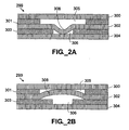
- FIGS. 2A-2B are cross-sectional views of at least a portion of a 5-layer microfluidic device having a larger upper channel region and a smaller lower channel region.
- FIG. 2A illustrates the membrane being deformed toward and into the smaller lower channel region.
- FIG. 2B illustrates the membrane being deformed toward and into the larger, upper channel region.
- FIGS. 3A-3B are cross-sectional views of at least a portion of a microfluidic device having three separate channel regions (an upper, a central; and a lower channel region) divided by two deformable membranes (an upper and a lower membrane).
- FIG. 3A illustrates both membranes in neutral positions.
- FIG. 3B illustrates the upper deformable membrane being deflected toward and into the central channel region
- FIG. 3C illustrates both the upper and the lower deformable membrane being deflected toward and into the central channel region.
- FIG. 30 illustrates the lower deformable membrane being deflected toward and into the central channel region.
- FIG. 3A illustrates both membranes in neutral positions.
- FIG. 3B illustrates the upper deformable membrane being deflected toward and into the central channel region
- FIG. 3C illustrates both the upper and the lower deformable membrane being deflected toward and into the central channel region.
- FIG. 30 illustrates the lower deformable membrane being deflected toward and
- 3E illustrates both the upper and lower deformable membrane being deflected away from the central channel region, namely, the upper deformable membrane being deflected toward and into the upper channel region, and the lower deformable membrane being deflected toward and into the lower channel region.
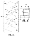
- FIG. 4A is an exploded perspective view of a five-layer microfluidic device having a pressure-activated regulating valve that controls fluid flow within the device
- FIG. 4B is a top view of the assembled device of FIG. 4A .
- FIG. 5A is an exploded perspective view of a five-layer microfluidic device capable of delivering a relatively constant flow rate of fluid over a large range of pressures.
- FIG. 5B is a top view of the assembled device of FIG. 5A
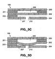
- FIG. 5C is a cross-sectional view of a portion of the microfluidic device of FIGS. 5A-5B along section lines "A-A" shown in FIG. 5B, with the regulatory region in the open position.
- FIG. 5D provides the same cross-sectional view as FIG. 5C, but with the regulatory region in the closed position.
- FIG. 5E is a chart showing the flow rates achieved at the unregulated and regulated outlets of the device shown in FIGS. 5A-5D over a range of input pressures. with each outlet tested separately white the other outlet was seated.
- FIG. 5F is a chart showing the flow rates at both the unregulated and regulated outlets of the device shown in FIGS. 5A-5D over a range of input pressures, measured with both outlets open.
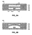
- FIG. 6A is a cross-sectional view of a portion of a microfluidic device having three channel segments that meet at a regulatory region and that are separated by a single deformable membrane.
- FIG. 6B provides the same cross-sectional view as FIG. 6A, but with the membrane deflected toward and into the upper channel segment.
- FIG. 7A is a cross-sectional view of at least a portion of a microfluidic device having a deformable membrane disposed above an aperture permitting fluid communication between two channels
- FIG. 7B provides the same cross-sectional view as FIG. 7A , but with the membrane deformed to seal the aperture and prevent fluid communication between the two channels.
- channel as used herein is to be interpreted in a broad sense, Thus, it is not intended to be restricted to alongated configurations where the transverse or longitudinal dimension greatly exceeds the diamater or cross-sectional dimension. Rather, the terms are meant to include cavities, tunnels, or chambers of any desired shape or configuration through which liquids may be directed.
- a fluid cavity may, for example, comprise a flow-through cell where fluid is to be continually passed or, alternatively, a chamber for holding a specified, discrete amount of fluid for a specified amount of time.
- Channels may be filled or may contain internal structures comprising valves or equivalent components.
- channel segment refers to a region of a channel.
- a "change in channel segment shape and geometry” indicates any change in the dimensions of a channel segment. For instance, the channel segment can become smaller, larger, change shape, be completely closed, be partially closed, be permanently restricted, etc.
- microfluidic as used herein is to be understood, without any restriction thereto, to refer to structures or devices through which fluid(s) are capable of being passed or directed, wherein one or more of the dimensions is less than 500 microns.
- stencil refers to a material layer that is preferably substantially planar, through which one or more variously shaped and oriented portions has been cut or otherwise removed through the entire thickness of the layer, and that permits substantial fluid movement within the layer (e . g ., in the form of channels or chambers, as opposed to simple through-holes for transmitting fluid through one layer to another layer).
- the outlines of the cut or otherwise removed portions form the lateral boundaries of microstructures that are formed upon sandwiching a stencil between substrates and/or other stencils.
- Microfluidic devices providing flow control utility may be fabricated in various ways using a wide variety of materials.
- microfluidic devices according to the present invention are constructed using stencil layers to define channels and/or chambers.
- a stencil layer is preferably substantially planar and has microstructure cut through the layer.
- a computer-controlled plotter modified to accept a cutting blade may be used to cut various patterns through a material layer.
- a computer-controlled laser cutter may be used.
- conventional stamping, cutting, and/or molding technologies may be employed to form stencil layers.
- stencil-based fabrication methods enable a particular device design to be rapidly “tuned” or optimized for particular operating parameters, since different material types and thicknesses may be readily used and/or substituted for individual layers within a device.
- the ability to prototype devices quickly with stencil fabrication methods permits many different variants of a particular design to be tested and evaluated concurrently.
- the top and bottom surfaces of stencil layers may mate with one or more adjacent stencil or substrate layers to form a substantially enclosed device, typically having one or more inlet ports and one or more outlet ports.
- one or more layers of a device are comprised of single- or double-sided adhesive tape, although other methods of adhering stencil layers may be used.
- a portion of the tape (of the desired shape and dimensions) can be cut and removed to form channels, chambers, and/or apertures.
- a tape stencil can then be placed on a supporting substrate, between layers of tape, or between layers of other materials.
- stencil layers can be stacked on each other.
- the thickness or height of the channels can be varied by varying the thickness of the stencil (e.g., the tape carrier and the adhesive material thereon) or by using multiple substantially identical stencil layers stacked on top of one another.
- Suitable tape carrier materials include but are not limited to polyesters, polycarbonates, polytetrafluoroethlyenes, polypropylenes. and polyimides. Such tapes may have various methods of curing, including curing by pressure, temperature, or chemical or optical interaction. The thicknesses of these carrier materials and adhesives may be varied.
- microfluidic devices according to the present invention are fabricated from materials such as glass, silicon, silicon nitride, quartz, or similar materials.
- materials such as glass, silicon, silicon nitride, quartz, or similar materials.
- Various conventional machining or micromachining techniques such as those known in the semiconductor industry may be used to fashion channels, vias, and/or chambers in tnese materials. For example, techniques including wet or dry etching and laser ablation may be used. Using such techniques, channels, chambers, and/or apertures may be made into one or more surfaces of a material or penetrate through a material.
- Still further embodiments may be fabricated from various materials using well-known techniques such as embossing, stamping, molding, and soft lithography.
- attachment techniques including thermal, chemical, or light-activated bonding; mechanical attachment (such as using clamps or screws to apply pressure to the layers); or other equivalent coupling methods may be used.
- a microfluidic device includes a first microfluidic channel segment and a second microfluidic channel segment that are separated by a deformable membrane at a regulatory region.
- the channels may be defined in horizontal layers of a device, with the deformable membrane forming a separate horizontal layer separating the channel layers.
- the channels can overlap at any suitable angle.
- the channels may be orthogonal, thus limiting the area of the overlap region, or they may be substantially parallel.
- the first and second channels also can be in fluid communication. Where the channels are in fluid communication, the use of the terms first channel segment and second channel segment refer to regions forming a channel disposed on different layers of the device.
- a change in relative pressure between the first and second channels results in deformation of the membrane separating the channels.
- the membrane is deformed towards the channel segment with lower relative pressure.
- the membrane can partially block flow of the fluid through the channel segment with lower relative pressure or can substantially block flow of the fluid through the channel segment with lower relative pressure.
- the degree of deformation of the deformable membrane is related to the differential pressure between the first and second channels. Generally, the greater the differential pressure, then the greater the observed deformation of the deformable membrane.
- FIGS. 1A-1C illustrate at least a portion of a microfluidic device 90 having a deformable membrane 102 that is responsive to changes in pressure between two channel segments 105, 106.
- the channel segments 105, 106 may be defined in stencil layers 101, 103 disposed between outer layers 100, 104.
- the deformable membrane 102 separates the first channel segment 105 defined in layer 101 from the second channel segment 106 defined in layer 103.
- the deformable membrane 102 adopts a neutral position, as shown in FIG. 1A . If the pressure in channel segment 105 is increased, or the pressure in channel segment 106 substantially decreased, then the deformable membrane 102 will deform towards channel segment 106, as shown in FIG.
- the deformable membrane 102 (specifically the lower surface 107 of the membrane 102) may contact the upper surface 108 of the outer layer 104.
- the deformable membrane 102 may deform into the channel segment 105, as shown in FIG. 1C.
- the deformable membrane 102 (specifically, the upper surface 109) will contact the lower surface 110 of substrate layer 100.
- the channel segment-containing portion of the device 90 can be constructed using any suitable materials, by any suitable technique.
- a microfluidic device is constructed with sandwiched stencil layers.
- the layers of the device containing channel segments may also be constructed from etched silicon, molded polymers, or using other materials or fabrication methods known to one skilled in the art of making microfluidic devices.
- the channel segment 105 could be surface etched into a single integral substrate substituted for separate layers 100 and 101.
- channel segment 106 could be etched into a single integral substrate substituted for separate layers 103 and 104.
- Microfluidic devices described herein may be constructed using still further techniques.
- channels are constructed in materials using etching, embossing, or molding techniques. Two or more different elements may be constructed. Then, the multiple elements may be assembled face-to-face with a deformable membrane disposed between them. The channels in the two etched or embossed devices may overlap in certain areas of the completed device with the deformable intermediary layer between the channel segments. Additionally, one or more apertures may be defined in the intermediate layer to serve as vias connecting the channels in the upper and lower devices. More complicated systems can be constructed.
- Control of the properties of the microfluidic device can be achieved by varying the deformable membrane material.
- the material can be elastically deformable or can be inelastically deformable.
- Suitable membrane materials include papers, foils and polymers.
- the membrane is a polymer including, for example, polyesters, polycarbonates, polytetrafluoroethylenes, polypropylenes, polyimides ( e . g ., KAPTON®) and polyesters ( e . g ., MYLAR®), silanes ( e.g. , PDMS) and polymethylmethacrylate (PMMA).
- a more rigid material will deflect less readily due to a change in pressure, while a more malleable material will deflect more easily.
- a membrane material also can be chosen based on its ability to perform repeated deformation cycles.
- the sensitivity of microfluidic device to changes in differential pressure may also be controlled by varying the thickness of the deformable membrane.
- a thinner membrane material will be more easily deformed and will respond more easily to changes in differential pressure.
- a thicker membrane will generally be less easily deformed and will be less sensitive to changes in relative pressure.
- the thickness or height of the channel segment into which the deformable channel segment moves also will impact the fluid control performance of the system.
- Adjacent microfluidic channels or chambers separated by a deformable membrane may be fashioned in a wide variety of sizes, shapes, and geometries. Channel or chamber segments can overlap in a perpendicular format, at an angle or along a length of channel segment that is parallel. Channels within a regulatory region may be formed with constant widths or variable widths.
- FIG. 5A-5B One example of a regulatory region is provided in FIG. 5A-5B , in which the regulatory region 207 is circular.
- FIGS. 2A-2B show at least a portion of a microfluidic device 299 comprising a plurality of device layers 300-304 and having, at the valve location, a relatively large channel segment 305 and a smaller channel segment 306 separated by deformable membrane 302.
- the membrane 302 in the valve region 308 deforms toward and into the smaller channel segment 306, as shown in FIG.
- channel segment 306 The small relative size of channel segment 306 means that the deformable membrane 302 only reduces the available cross section of channel segment 306 to about half its original size. However, when the relative pressure in channel segment 306 is higher than the pressure in channel segment 305, then the membrane 302 in the valve region 308 deforms toward and into the larger channel segment 305, as shown in FIG. 2B. Because of the relatively large area of the channel 305 bounded by the deformable portion of the membrane 302, the membrane 302 is able to move more easily into channel segment 305, thereby significantly changing the cross section of the channel segment 305.
- a membrane having a deformable portion 5 mm in diameter will deflect across a 3-mil (75 microns) channel segment more readily than a 2 mm diameter deformable membrane portion, because there is less of a percentage of deformation of the larger membrane.
- a channel subject to fluidic control defines an aperture opposite and substantial aligned with the center of a deformable membrane.
- a fluid flow path is provided in a direction parallel to the direction of travel of the deformable membrane.
- FIG. 5C shows at least a portion of a microfluidic device having a channel segment 207 in fluid communication with an aperture 210 aligned substantially centrally below the deformable membrane 202. Deformation of the membrane 202 towards channel segment 207 results in substantially complete blockage of fluid flow between channel segments 210 and 207.
- While similar devices can be constructed with the aperture disposed in various positions relative to the path of the deformable membrane, it is highly preferable to position the aperture near to the center of travel of the deformable a membrane to promote substantial blockage of the fluid flow path by the membrane.
- the size of the aperture will also affect the amount of pressure required to provide substantially leak-free sealing.
- a system can be constructed in which deformation of the material results in either partial blockage or substantially complete blockage of fluid flow through a channel segment.
- An elastic material may be used where reversible control of fluid flow is desired. Lowering the pressure in the higher relative pressure channel segment allows the deformable membrane to resume its neutral state, allowing unrestricted fluid flow.
- shut-off valving utility to protect downstream components from damage caused by high flow or pressure.
- an inelastic material Upon increase in pressure in one channel segment, an inelastic material will be plastically deformed towards the channel segment with lower pressure. The material will remain substantially in the deformed position. Such results may be obtained with semi-malleable materials including suitable metal foils.
- a deformable membrane also can be made of materials with surface properties that alter its behavior.
- a membrane can be tacky or have an adhesive coating. Such properties or coatings can be applied to one or both sides of the deformable membrane.
- the defonnable membrane can operate as a variable switch. At low relative pressures, the membrane can act elastically. At high pressures, or for systems designed for the deformable membrane to physically contact the opposing wall of the adjacent channel segment, the deformation can result in permanent or semi-permanent closure of the adjacent channel segment.
- the membrane used can be non-adhesive, but the surface against which it seals can be constructed with a tacky or adhesive surface. For example, in FIG.
- the lower surface 107 of the deformable membrane 101 can be coated with an adhesive, or can be constructed from an adhesive tape, such that upon deformation sufficient to provided contact between the membrane 102 and the lower layer 104, the deformable membrane 102 can be affixed to the upper surface 108 of the lower layer 104.
- the degree of permanence of the closure depends on factors including elasticity of the membrane and the strength of the adhesive material used. Similar results can be achieved by coating the upper surface 108 with adhesive or both surfaces 107 and 108 with adhesive, or by forming one or more of these surfaces from single- or double-sided self-adhesive tape materials. Referring to FIG.
- the bottom surface of the membrane 107 or the upper surface 108 of the bottom layer 104 may include permanent or semi-permanent adhesives.
- the membrane 102 When the membrane 102 is deformed, such as by an elevated pressure within the upper chamber 105, then the membrane 102 may be deformed to contact the lower layer 104 to permit the adhesive to bind the surfaces together and permanently or semi-permanently obstruct the lower channel segment 106.
- the membrane 102 may be deformed and adhered to the lower surface in a semi-permanent manner that may be reversed by further manipulation. For example, when pressure is applied to 105, the membrane 102 is deformed so as to the contact the lower layer 104, where the membrane 102 and the upper surface 108 of the lower layer 104 are adhesively bound. Alternatively, the membrane 102 may be plastically deformed into the lower channel 106. When the pressure is re-equalized between the upper and lower chambers 105, 106, the membrane 102 will remain affixed to the lower layer 104 until sufficient pressure is applied to channel segment 106 to overcome the adhesive bond or plastic deformation of the membrane 102. In many cases, the pressure required to reposition ( i . e ., re-deform) the membrane 102 may be greater than the pressure to originally deform it.
- a microfluidic valve may include two microfluidic channels separated by a seating surface defining an aperture for mating with a deformable membrane to provide flow control utility.
- FIGS. 7A-7B illustrate a microfluidic device 197 fabricated from seven layers 200-204, 220, 221 and having a control channel 205 bounded in part by a deformable membrane 202. With the deformable membrane in a relaxed, neutral state, fluid flow may be established between a first channel 207 and a second channel 222 defined in different layers 203, 220 of the device 197 and separated by a seating layer 204 defining an aperture 210.
- the deformable membrane 202 is disposed substantially centrally above the aperture 210 to promole tight sealing of the aperture when the control channel 205 is pressurized to deform the membrane 202 to contact the seating layer 204, as shown in FIG. 7B.
- the valve seating layer 204 adjacent to the aperture 210 may be considered a valve seating surface.
- the device 197 thus serves as a normally open valve that permits flow through the aperture when the deformable membrane is in an undeformed state. Selective pressurization of the control channel 205 permits closure of the valve.
- Either or both of the membrane 202 and the seating layer 204 may be provided with an adhesive surface to provide latching valve utility.
- more complex fluid control structures utilizing multiple membranes may be formed.
- more than two channels can meet at a valve region separated by one or more membranes.
- more than one pressure regulator may be stacked in a given vertical position of a microfluidic device.
- three channels overlap at a single valve region, with two deformable membranes separating the various channels.
- FIGS. 3A-3E show five cross-sectional views of such an overlap.
- FIG. 3A shows a cross-section of at least a portion of a microfluidic device 119 formed using sandwiched stencils, the device having seven layers 120-126 and forming three channel segment / chamber regions 127-129.
- the central stencil layer 123 has a greater height than the other layers, and the layers 122 and 124 are flexible or deformable membranes. Fluid flow through the central channel segment 128 is affected by both the upper chamber region 127 and the lower chamber region 129.
- FIG. 3B shows the central channel segment 128 being partially blocked following a pressure increase within the upper chamber 127, causing deflection of the upper membrane 122 toward and into the central channel 128.
- FIG. 3C shows the channel segment 128 being substantially (almost completely) blocked following pressure increases in both the upper and lower chamber 127, 129, which cause both membranes 122, 124 to deform toward and into the central channel 128.
- FIG. 3B shows the central channel segment 128 being partially blocked following a pressure increase within the upper chamber 127, causing deflection of the upper membrane 122 toward and into the central channel 128.
- FIG. 3C shows the channel segment 128 being substantially (almost completely) blocked following pressure increases in both the upper and lower chamber 127, 129, which cause both membrane
- 3D shows another operating state wherein the channel segment 128 is partially blocked following a pressure increase in the lower chamber region 129.
- the central channel segment 128 is enlarged in response to a reduced pressure in both the upper and lower chambers 127, 129.
- a differential pressure can be generated between a first and a second channel segment either by increasing the pressure in one channel segment, or through a relative decrease in pressure in one channel segment.
- the pressure of a fluid (encompassing both liquids and gases) can be increased by a pump such as, for example, a syringe or other mechanically operated pump.
- Reduced pressure can be achieved in the channel segment by applying a vacuum to a channel segment, for example using a vacuum pump.
- a channel segment is pressurized to greater than atmospheric pressure and a pressure reduction is desired. then the pressure can be reduced by venting the channel segment to the atmosphere or to a lower-pressure reservoir. Pressure can also be controlled by changing the temperature within one channel segment of the device.
- the fluid within the channel segment undergoes a large volume change with changing temperature.
- the fluid is a gas.
- the pressure can be increased by raising the temperature of the gas within the channel segment and can be decreased by lowering the temperature within the channel segment.
- the pressure within a channel segment also can be changed by processes such as vaporization or electrolysis (a process in which an electric current is used to break a liquid within a channel segment into gaseous components). For example, water may be electrolyzed into hydrogen gas and oxygen gas.
- a flow control device can have more than one channel segment on a given layer at a regulatory region.
- a microfluidic device 699 comprises a plurality of device layers 700-704 and includes two channel segments 706 and 707 defined in layer 703 and separated by a deformable membrane 702 from a channel segment 705 defined in an upper layer 701.
- the deformable membrane 702 is not adhered a seating region 703A defined in the layer 703.
- the pressure in the channel segment 705 is high relative to both channels 706 and 707, then fluid communication between the channels 706 and 707 within the regulatory region is prevented by the membrane 702 pressed into contact with the seating region 703A, such as shown in FIG. 6A .
- both channels 706 and 707 are higher than that in the channel 705, such as shown in FIG. 6B , then the membrane 702 will deform toward and into the channel segment 705, thus allowing fluidic passage between the channels 706 and 707.
- Factors affecting whether an increased pressure in channel segments 706 or 707 is sufficient to open a flow path between the channels include the size of the seating region, the thickness and composition of the flexible membrane 702, and the size of the regulatory region (which affects the size of the membrane subject to deformation).
- pressure-sensitive regions may be integrated into a microfluidic device to provide internal feedback, such that a change in pressure or flow rate within one region of a channel segment will affect another region.
- a feedback loop is used to create a pressure regulation device.
- a microfluidic device is constructed where a first channel segment located in one layer of a three-dimensional device is in fluid communication with a second channel segment in another layer of the device.
- the two channels in distinct layers may be connected through a via or through-note between layers.
- one channel segment is positioned so that it passes back over the other channel segment in a lower layer. This upper section can pass over the lower region one or more times and can pass over the channel segment in parallel along its axis or cross the channel segment at an angle.
- a deformable membrane separates the two channel segments at a regulatory region.
- a pressure increase in the upstream part of the channel segment will cause the first channel segment to expand, thus compressing the overlapping downstream part of the channel segment. This will deform the membrane towards the second channel segment, altering the shape or geometry of the second . channel segment.
- the flow through the second segment also can decrease, and will vary depending on the design of the regulatory region and with the pressure applied.
- the membrane can provide a partial blockage or a substantially complete blockage to fluid flow through one channel segment.
- a subsequent decrease in the pressure within the channel segment will result in said channel segment attaining its previously unrestricted or "relaxed" neutral state.
- a pressure-activated valve can regulate flow between two channel segments in a single microfluidic channel because of the pressure-drop that occurs "downstream" in microfluldic channels.
- the pressure within a microfluidic channel decreases with distance from the inlet port. At low input pressures, there is a minimal pressure drop in a long channel segment. As the input pressure increases, it becomes more difficult for the internal pressures to equalize, and the pressure differential from one end of a channel segment to the other is much larger. The higher the operating pressure of the microfluidic device, the greater the pressure differential generated over the length of a channel.
- shut-off pressures can be designed or "programmed" into the device.
- a relatively long channel segment connects the one side of the shut-off valve membrane and the other; a long channel segment length is preferably provided to create the pressure differential.
- FIGS. 4A-4B A microfluidic device with a built in pressure regulation system is shown in FIGS. 4A-4B.
- a microfluidic device 130 was constructed using a sandwiched stencil fabrication method from five layers 131-135.
- the first layer 131 defines one inlet port 136 and two outlet ports 137,138.
- the second layer 132 defines two vias 140 and a channel segment 139 having a nominal width of 40 mils (1000 microns).
- the third layer 133 defines a central via 141 and two lateral vias 142.
- the fourth layer 134 defines a channel 143 also having a nominal width of 40 mils (1000 microns). All of the vias are 70 mils (1750 microns) in diameter.
- the layers 131-134 are all constructed from 3 mil (75 microns) thickness single-sided tape comprising a polypropylene carrier with a water-based adhesive.
- the bottom layer is a 0.25 inch (6.3 mm) thick block of acrylic.
- fluid is injected at inlet port 136 at a low backpressure.
- the fluid passes through channel segment 139 until it reaches Junction point 144.
- the fluid then splits evenly down the two parts of channel segment 143 until it reaches the outlet ports 137 and 138.
- the fluid splits evenly at the junction point 144 and is divided evenly.
- the pressure within the channel segment increased, as did the flow rate.
- the pressure in the upper channel segment 139 pushes on the polymeric membrane 133 that separates the two channels.
- the polymer material 133 is locally deformed and partially blocks the lower channel segment 143, thus partially restricting the flow in that channel segment.
- the size of the exit channels are adjusted such that the flow out of the device 130 remains constant no matter what backpressure is applied.
- This device 130 may be used in various applications, including but not limited to constant delivery of materials such as in drug delivery applications.
- inlet port 136 is connected to a pressurized container of fluid (not shown) that contains a drug of interest.
- the outlet ports 137, 138 are connected to a delivery mechanism to a body.
- the pressurized container is full, the backpressure is high and the outlet 137 is dosed and 138 is open.
- the pressure remains high, the resistance in the channels is even higher since there is only one outlet.
- the pressurized body loses fluid, the pressure decreases which permits the exit port 137 to slowly open. As the pressure drops, the resistance in the channels decreases since two channels are now open.
- a more complicated structure with many feedback loops can be constructed so that approximately constant flow can be maintained over a large range of input pressures.
- a microfluidic device was constructed to regulate flow rate over a large range of input pressures.
- a microfluidic flow regulation device 199 was constructed using a stencil fabrication method from five layers 200-204. Starting from the bottom, the first layer 204 defined one inlet port 209 and two outlet ports 210, 211. The second layer 203 defined a via 214 and a channel 206 terminating at a chamber 207. The third layer 202 defined two vias 208, 208A. The fourth layer 201 defined a channel 205 and connected chamber 215. The fifth layer 200 served as a cover for the fourth layer 201. The assembled device is shown in FIG. 5B.
- the overlap region 212 is shown in cross section in FIGS. 6C-6D with the valve in open and closed positions, respectively.
- fluid is injected into the inlet port 209.
- the fluid travels through the vias 214, 208, through channel segment 205, down through the via 208A and the channel 206 and is split towards the two exit ports 210 and 211.
- the inlet pressure is relatively low, the flexible membrane 202 is not substantially deformed (see FIG. 5C ) and the fluid passes evenly out of the two exit ports 210, 211.
- the pressure at the inlet is increased, the pressure in the channel 205 and chamber 215 increases, thus deforming the membrane 202 (see FIG. 5D ) and partially blocking the outlet port 210.
- FIGS. 7A-7B A structure substantially similar to that illustrated in FIGS. 5C-5D is provided in FIGS. 7A-7B, with the primary difference being the addition of outlet channels 222 defined by stencil layer 220 and a substrate 221 to continue flow within the device 197.
Landscapes
- Chemical & Material Sciences (AREA)
- General Engineering & Computer Science (AREA)
- Engineering & Computer Science (AREA)
- Dispersion Chemistry (AREA)
- Mechanical Engineering (AREA)
- Health & Medical Sciences (AREA)
- Hematology (AREA)
- Chemical Kinetics & Catalysis (AREA)
- Clinical Laboratory Science (AREA)
- General Health & Medical Sciences (AREA)
- Analytical Chemistry (AREA)
- Physical Or Chemical Processes And Apparatus (AREA)
- Micromachines (AREA)
- Flow Control (AREA)
- Magnetically Actuated Valves (AREA)
- Reciprocating Pumps (AREA)
Claims (5)
- Mikro-Fluid-Regelvorrichtung (90, 119, 130, 197, 199, 299) aufweisend: ein erstes Kanalsegment (105, 127, 129, 139, 205, 305), das in einer ersten Vorrichtungsschicht (101, 121, 125, 132, 201, 301) der Mikro-Fluid-Regelvorrichtung definiert ist, und ein zweites Kanalsegment (106, 128, 143, 206, 207, 306), das in einer zweiten Vorrichtungsschicht (103, 123, 134, 203, 303) der Mikro-Fluid-Regelvorrichtung definiert ist, wobei das zweite Kanalsegment (106, 128, 143, 206, 207, 306) in Fluidkommunikation mit dem ersten Kanalsegment (105, 127, 129, 139, 205, 305) steht, und wobei die Vorrichtung (90, 119, 130, 197, 199, 299) ferner eine deformierbare Membran (102, 122, 124, 133, 202, 302) aufweist, die das erste Kanalsegment (105, 127, 129, 139, 205, 305) und das zweite Kanalsegment (106, 128, 143, 206, 207, 306) an einer Regelregion (145, 207, 215, 217) voneinander trennt, dadurch gekennzeichnet, dass die deformierbare Membran über einen Druckunterschied zwischen dem ersten Kanalsegment (105, 127, 129, 139, 205, 305) und dem zweiten Kanalsegment (106, 128, 143, 206, 207, 306) in Richtung und in das Kanalsegment mit einem niedrigeren Innendruck deformierbar ist, wodurch die Fluid-Flussmöglichkeit durch das erste Kanalsegment oder das zweite Kanalsegment reduziert wird, wobei die deformierbare Membran (102, 122, 124, 133, 202, 302), das erste Kanalsegment (105, 127, 129, 139, 205, 305) und das zweite Kanalsegment (106, 128, 143, 206, 207, 306) eine Druckregel-Rückkopplungsschleife (130, 199) bilden und zumindest die erste Vorrichtungsschicht (101, 121, 125, 132, 201, 301) und die zweite Vorrichtungsschicht (103, 123, 134, 203, 303) eine zwischenliegende Matrizenschicht (132, 134, 203) aufweisen.
- Mikro-Fluid-Regelvorrichtung (90, 119, 130, 197, 199, 299) nach Anspruch 1, wobei zumindest eine der ersten Vorrichtungsschicht (101, 121, 125, 132, 201, 301), der zweiten Vorrichtungsschicht (103, 123, 134, 203, 303) und der Membran (102, 122, 124, 133, 202, 302) eine haftende Oberfläche hat.
- Mikro-Fluid-Regelvorrichtung (90, 119, 130, 197, 199, 299) gemäß einem der vorangegangenen Ansprüche, wobei zumindest eine der ersten Vorrichtungsschicht (101, 121, 125, 132, 201, 301), der zweiten Vorrichtungsschicht (103, 123, 134, 203, 303) und der Membran (102, 122, 124, 133, 202, 302) ein selbstklebendes Bandmaterial aufweist.
- Mikro-Fluid-Regelvorrichtung (90, 119, 130, 197, 199, 299) gemäß einem der vorangegangenen Ansprüche, wobei die Membran (102, 122, 124, 133, 202, 302) elastisch verformbar ist.
- Mikro-Fluid-Regelvorrichtung (90, 119, 130, 197, 199, 299) gemäß einem der vorangegangenen Ansprüche, wobei die Membran (102, 122, 124, 133, 202, 302) aus einem Polymermaterial besteht, das aus der Gruppe ausgewählt wurde, die aus Polyestern, Polycarbonaten, Polytetrafluorethylenen, Polypropylenen, Polyimiden, Polysilanen und Polymethylmethacrylaten besteht.
Applications Claiming Priority (3)
| Application Number | Priority Date | Filing Date | Title |
|---|---|---|---|
| US24613800P | 2000-11-06 | 2000-11-06 | |
| US246138P | 2000-11-06 | ||
| PCT/US2001/042981 WO2002055198A2 (en) | 2000-11-06 | 2001-11-06 | Microfluidic flow control devices |
Publications (2)
| Publication Number | Publication Date |
|---|---|
| EP1331997A2 EP1331997A2 (de) | 2003-08-06 |
| EP1331997B1 true EP1331997B1 (de) | 2004-06-16 |
Family
ID=22929445
Family Applications (1)
| Application Number | Title | Priority Date | Filing Date |
|---|---|---|---|
| EP01270103A Expired - Lifetime EP1331997B1 (de) | 2000-11-06 | 2001-11-06 | Mikrofluidische durchflussregelvorrichtung |
Country Status (6)
| Country | Link |
|---|---|
| US (2) | US20030196695A1 (de) |
| EP (1) | EP1331997B1 (de) |
| AT (1) | ATE269162T1 (de) |
| AU (1) | AU2002253781A1 (de) |
| DE (1) | DE60103924T2 (de) |
| WO (1) | WO2002055198A2 (de) |
Cited By (3)
| Publication number | Priority date | Publication date | Assignee | Title |
|---|---|---|---|---|
| DE102009041325A1 (de) | 2008-09-19 | 2010-05-12 | GeSIM Gesellschaft für Silizium-Mikrosysteme mbH | Mikroventil zum Schalten von Kanälen in Mikroflusssystemen |
| CN104492510A (zh) * | 2014-12-05 | 2015-04-08 | 苏州国环环境检测有限公司 | 一种二维微流控纸芯片及其制作方法 |
| EP4430312A4 (de) * | 2021-11-13 | 2025-03-19 | Gao, Run Ze | Mikrofluidische ventile und kanäle sowie minifluidische ventile und kanäle für weiche robotervorrichtung, kleidung und verfahren |
Families Citing this family (152)
| Publication number | Priority date | Publication date | Assignee | Title |
|---|---|---|---|---|
| US7378280B2 (en) * | 2000-11-16 | 2008-05-27 | California Institute Of Technology | Apparatus and methods for conducting assays and high throughput screening |
| US6674525B2 (en) * | 2001-04-03 | 2004-01-06 | Micronics, Inc. | Split focusing cytometer |
| AU2002307152A1 (en) | 2001-04-06 | 2002-10-21 | California Institute Of Technology | Nucleic acid amplification utilizing microfluidic devices |
| US7318912B2 (en) * | 2001-06-07 | 2008-01-15 | Nanostream, Inc. | Microfluidic systems and methods for combining discrete fluid volumes |
| US7465382B2 (en) * | 2001-06-13 | 2008-12-16 | Eksigent Technologies Llc | Precision flow control system |
| US20020189947A1 (en) | 2001-06-13 | 2002-12-19 | Eksigent Technologies Llp | Electroosmotic flow controller |
| US7118910B2 (en) | 2001-11-30 | 2006-10-10 | Fluidigm Corporation | Microfluidic device and methods of using same |
| US20040109793A1 (en) * | 2002-02-07 | 2004-06-10 | Mcneely Michael R | Three-dimensional microfluidics incorporating passive fluid control structures |
| CA2480728A1 (en) | 2002-04-01 | 2003-10-16 | Fluidigm Corporation | Microfluidic particle-analysis systems |
| US7312085B2 (en) | 2002-04-01 | 2007-12-25 | Fluidigm Corporation | Microfluidic particle-analysis systems |
| US6808075B2 (en) | 2002-04-17 | 2004-10-26 | Cytonome, Inc. | Method and apparatus for sorting particles |
| US9943847B2 (en) | 2002-04-17 | 2018-04-17 | Cytonome/St, Llc | Microfluidic system including a bubble valve for regulating fluid flow through a microchannel |
| US6976590B2 (en) | 2002-06-24 | 2005-12-20 | Cytonome, Inc. | Method and apparatus for sorting particles |
| US6877528B2 (en) * | 2002-04-17 | 2005-04-12 | Cytonome, Inc. | Microfluidic system including a bubble valve for regulating fluid flow through a microchannel |
| US20030210799A1 (en) * | 2002-05-10 | 2003-11-13 | Gabriel Kaigham J. | Multiple membrane structure and method of manufacture |
| US6805809B2 (en) * | 2002-08-28 | 2004-10-19 | Board Of Trustees Of University Of Illinois | Decal transfer microfabrication |
| JP2006501056A (ja) * | 2002-09-25 | 2006-01-12 | カリフォルニア インスティテュート オブ テクノロジー | ミクロ流体大規模集積 |
| US8220494B2 (en) * | 2002-09-25 | 2012-07-17 | California Institute Of Technology | Microfluidic large scale integration |
| AU2003299541A1 (en) | 2002-10-02 | 2004-05-25 | California Institute Of Technology | Microfluidic nucleic acid analysis |
| DE10254312B4 (de) * | 2002-11-21 | 2005-04-21 | Hahn-Schickard-Gesellschaft für angewandte Forschung e.V. | Variabler Flußwiderstand |
| KR20050088476A (ko) * | 2002-12-30 | 2005-09-06 | 더 리전트 오브 더 유니버시티 오브 캘리포니아 | 병원균 검출과 분석을 위한 방법과 기구 |
| GB0303920D0 (en) * | 2003-02-21 | 2003-03-26 | Sophion Bioscience As | Capillary stop |
| US7604965B2 (en) | 2003-04-03 | 2009-10-20 | Fluidigm Corporation | Thermal reaction device and method for using the same |
| WO2004101734A1 (ja) * | 2003-05-19 | 2004-11-25 | Japan Science And Technology Agency | 細胞培養用マイクロチャンバー |
| WO2005060393A2 (en) * | 2003-08-11 | 2005-07-07 | California Institute Of Technology | Microfluidic large scale integration |
| WO2005043112A2 (en) * | 2003-09-30 | 2005-05-12 | West Virginia University Research Corporation | Apparatus and method for edman degradation on a microfluidic device utilizing an electroosmotic flow pump |
| US7867194B2 (en) | 2004-01-29 | 2011-01-11 | The Charles Stark Draper Laboratory, Inc. | Drug delivery apparatus |
| WO2005072793A1 (en) | 2004-01-29 | 2005-08-11 | The Charles Stark Draper Laboratory, Inc. | Implantable drug delivery apparatus |
| US20050196321A1 (en) * | 2004-03-03 | 2005-09-08 | Zhili Huang | Fluidic programmable array devices and methods |
| US7819822B2 (en) | 2004-03-06 | 2010-10-26 | Roche Diagnostics Operations, Inc. | Body fluid sampling device |
| PL2705792T3 (pl) | 2004-03-06 | 2015-10-30 | Hoffmann La Roche | Urządzenie do pobierania próbki płynu ustrojowego |
| US20070095393A1 (en) * | 2004-03-30 | 2007-05-03 | Piero Zucchelli | Devices and methods for programmable microscale manipulation of fluids |
| US8642353B2 (en) * | 2004-05-10 | 2014-02-04 | The Aerospace Corporation | Microfluidic device for inducing separations by freezing and associated method |
| US7694694B2 (en) * | 2004-05-10 | 2010-04-13 | The Aerospace Corporation | Phase-change valve apparatuses |
| US7721762B2 (en) * | 2004-06-24 | 2010-05-25 | The Aerospace Corporation | Fast acting valve apparatuses |
| US7650910B2 (en) * | 2004-06-24 | 2010-01-26 | The Aerospace Corporation | Electro-hydraulic valve apparatuses |
| US7686040B2 (en) * | 2004-06-24 | 2010-03-30 | The Aerospace Corporation | Electro-hydraulic devices |
| JP4613367B2 (ja) * | 2004-08-30 | 2011-01-19 | スパンション エルエルシー | 積層型半導体装置用キャリア構成、この製造方法及び積層型半導体装置の製造方法 |
| US7608160B2 (en) * | 2004-10-13 | 2009-10-27 | Rheonix, Inc. | Laminated microfluidic structures and method for making |
| US7832429B2 (en) * | 2004-10-13 | 2010-11-16 | Rheonix, Inc. | Microfluidic pump and valve structures and fabrication methods |
| US7837821B2 (en) | 2004-10-13 | 2010-11-23 | Rheonix, Inc. | Laminated microfluidic structures and method for making |
| US7662545B2 (en) * | 2004-10-14 | 2010-02-16 | The Board Of Trustees Of The University Of Illinois | Decal transfer lithography |
| US20080135484A1 (en) * | 2004-10-18 | 2008-06-12 | Hammer Michael R | Liquid Chromatography Apparatus |
| US9260693B2 (en) | 2004-12-03 | 2016-02-16 | Cytonome/St, Llc | Actuation of parallel microfluidic arrays |
| US7540469B1 (en) | 2005-01-25 | 2009-06-02 | Sandia Corporation | Microelectromechanical flow control apparatus |
| JP2008537063A (ja) * | 2005-01-31 | 2008-09-11 | プレジデント・アンド・フエローズ・オブ・ハーバード・カレツジ | マイクロ流体システムのためのバルブおよび貯蔵器 |
| EP1888224B1 (de) * | 2005-04-04 | 2015-12-09 | Avantium International B.V. | System und verfahren zur durchführung eines chemischen experiments |
| AU2012200887B2 (en) * | 2005-08-23 | 2015-02-12 | University Of Virginia Patent Foundation | Passive components for micro-fluidic flow profile shaping and related method thereof |
| AU2006283177B2 (en) * | 2005-08-23 | 2011-11-17 | University Of Virginia Patent Foundation | Passive components for micro-fluidic flow profile shaping and related method thereof |
| CA2620629A1 (en) * | 2005-09-02 | 2007-03-08 | California Institute Of Technology | Method and apparatus for the mechanical actuation of valves in fluidic devices |
| US20080271799A1 (en) * | 2005-09-20 | 2008-11-06 | Koninklijke Philips Electronics, N.V. | Microfluidic Regulating Device |
| KR100984963B1 (ko) | 2005-09-29 | 2010-10-05 | 지멘스 메디컬 솔루션즈 유에스에이, 인크. | 양전자 방출 단층촬영에 의한 인체 영상화에 적합한 규모의방사성 표지 분자를 합성할 수 있는 마이크로유체 칩 |
| EP1790861A1 (de) * | 2005-11-25 | 2007-05-30 | Bonsens AB | Mikrofluidisches System |
| US7976795B2 (en) * | 2006-01-19 | 2011-07-12 | Rheonix, Inc. | Microfluidic systems |
| JP2009525443A (ja) | 2006-02-03 | 2009-07-09 | シーメンス・メディカル・ソルーションズ・ユーエスエイ、インコーポレイテッド | エラストマー製の通気性ガスケットを有するマイクロ流体構造及び該マイクロ流体構造の使用方法 |
| US7862000B2 (en) * | 2006-02-03 | 2011-01-04 | California Institute Of Technology | Microfluidic method and structure with an elastomeric gas-permeable gasket |
| GB2448858A (en) * | 2006-02-15 | 2008-11-05 | Aida Eng Ltd | Microchannel chip and method for manufacturing such chip |
| US7815868B1 (en) | 2006-02-28 | 2010-10-19 | Fluidigm Corporation | Microfluidic reaction apparatus for high throughput screening |
| US7766033B2 (en) * | 2006-03-22 | 2010-08-03 | The Regents Of The University Of California | Multiplexed latching valves for microfluidic devices and processors |
| JP4721227B2 (ja) * | 2006-05-22 | 2011-07-13 | アイダエンジニアリング株式会社 | マイクロ流路チップ及びその製造方法 |
| CN101501792A (zh) * | 2006-08-15 | 2009-08-05 | 皇家飞利浦电子股份有限公司 | 磁场产生装置 |
| WO2008036045A1 (en) | 2006-09-19 | 2008-03-27 | Agency For Science, Technology And Research | A dispenser arrangement for fluidic dispensing control in microfluidic system |
| WO2008036997A1 (en) * | 2006-09-28 | 2008-04-03 | Fluidyx Pty. Limited | A system and method for controlling fluids within a microfluidic device |
| US20080131327A1 (en) * | 2006-09-28 | 2008-06-05 | California Institute Of Technology | System and method for interfacing with a microfluidic chip |
| ES2653572T3 (es) * | 2006-10-18 | 2018-02-07 | The New Zealand Institute For Plant And Food Research Limited | Válvula de liberación de fluidos que usa una membrana flexible permeable a los fluidos |
| WO2008052138A2 (en) | 2006-10-25 | 2008-05-02 | The Regents Of The University Of California | Inline-injection microdevice and microfabricated integrated dna analysis system using same |
| US7534397B2 (en) * | 2006-12-08 | 2009-05-19 | Nicolae Dumitrescu | Sample preparation device |
| US8315817B2 (en) * | 2007-01-26 | 2012-11-20 | Illumina, Inc. | Independently removable nucleic acid sequencing system and method |
| US12497656B2 (en) | 2007-01-26 | 2025-12-16 | Illumina, Inc. | Independently removable nucleic acid sequencing system and method |
| US7835871B2 (en) * | 2007-01-26 | 2010-11-16 | Illumina, Inc. | Nucleic acid sequencing system and method |
| WO2008089769A2 (en) * | 2007-01-26 | 2008-07-31 | Diramo A/S | Pressurized reservoir for an analysis system |
| WO2008094672A2 (en) | 2007-01-31 | 2008-08-07 | Charles Stark Draper Laboratory, Inc. | Membrane-based fluid control in microfluidic devices |
| EP1970122A1 (de) * | 2007-03-12 | 2008-09-17 | Koninklijke Philips Electronics N.V. | Mikrofluidisches System auf der Basis von magnetischen Aktuatorelementen |
| US8133629B2 (en) | 2007-03-21 | 2012-03-13 | SOCIéTé BIC | Fluidic distribution system and related methods |
| US8679694B2 (en) * | 2007-03-21 | 2014-03-25 | Societe Bic | Fluidic control system and method of manufacture |
| KR101462131B1 (ko) | 2007-03-21 | 2014-11-17 | 소시에떼 비아이씨 | 유체 다기관 및 그 방법 |
| US7906074B2 (en) * | 2007-04-09 | 2011-03-15 | Auburn University | Microfluidic array system for biological, chemical, and biochemical assessments |
| US8071035B2 (en) | 2007-04-12 | 2011-12-06 | Siemens Medical Solutions Usa, Inc. | Microfluidic radiosynthesis system for positron emission tomography biomarkers |
| WO2008137997A1 (en) * | 2007-05-08 | 2008-11-13 | The Regents Of The University Of California | Microfluidic device having regulated fluid transfer between elements located therein |
| US8016260B2 (en) | 2007-07-19 | 2011-09-13 | Formulatrix, Inc. | Metering assembly and method of dispensing fluid |
| US8206025B2 (en) | 2007-08-07 | 2012-06-26 | International Business Machines Corporation | Microfluid mixer, methods of use and methods of manufacture thereof |
| EP2200931B1 (de) * | 2007-09-19 | 2017-06-07 | The Charles Stark Draper Laboratory, Inc. | Mikrofluidstrukturen mit kreisförmigem querschnitt |
| JP5523327B2 (ja) | 2007-10-12 | 2014-06-18 | レオニックス,インコーポレイテッド | 統合型マイクロ流体デバイスおよび方法 |
| KR100931302B1 (ko) | 2008-02-05 | 2009-12-11 | 한국과학기술원 | 서로 다른 임계압력을 가지는 밸브를 이용한 마이크로유체분배기 |
| KR100969667B1 (ko) | 2008-03-24 | 2010-07-14 | 디지탈 지노믹스(주) | 생리활성물질을 전기적으로 검출하는 방법 및 이를 위한바이오칩 |
| CN102056838B (zh) * | 2008-04-11 | 2013-07-03 | 弗卢丁公司 | 微流体装置和方法 |
| US8961902B2 (en) * | 2008-04-23 | 2015-02-24 | Bioscale, Inc. | Method and apparatus for analyte processing |
| DK2138233T3 (da) * | 2008-06-02 | 2011-01-31 | Boehringer Ingelheim Micropart | Mikrofluid foliestruktur til dosering af væsker |
| US9017946B2 (en) | 2008-06-23 | 2015-04-28 | Canon U.S. Life Sciences, Inc. | Systems and methods for monitoring the amplification of DNA |
| US8122901B2 (en) | 2008-06-30 | 2012-02-28 | Canon U.S. Life Sciences, Inc. | System and method for microfluidic flow control |
| US20100102261A1 (en) * | 2008-10-28 | 2010-04-29 | Microfluidic Systems, Inc. | Microfluidic valve mechanism |
| TWI383146B (zh) * | 2008-11-19 | 2013-01-21 | Univ Nat Cheng Kung | Can be accurate micro sampling and sample of microfluidic chip |
| JP4824743B2 (ja) * | 2008-12-26 | 2011-11-30 | アイダエンジニアリング株式会社 | マイクロ流路チップ |
| US8058630B2 (en) | 2009-01-16 | 2011-11-15 | Fluidigm Corporation | Microfluidic devices and methods |
| US8100293B2 (en) | 2009-01-23 | 2012-01-24 | Formulatrix, Inc. | Microfluidic dispensing assembly |
| DE102009023429B4 (de) | 2009-05-29 | 2013-08-14 | Siemens Aktiengesellschaft | Ventil für Lab-on-a-Chip-Systeme, Verfahren zum Betätigen und zur Herstellung des Ventils |
| US20110082563A1 (en) * | 2009-10-05 | 2011-04-07 | The Charles Stark Draper Laboratory, Inc. | Microscale multiple-fluid-stream bioreactor for cell culture |
| US8965076B2 (en) | 2010-01-13 | 2015-02-24 | Illumina, Inc. | Data processing system and methods |
| DE102010001412A1 (de) * | 2010-02-01 | 2011-08-04 | Robert Bosch GmbH, 70469 | Mikrofluidisches Bauelement zur Handhabung eines Fluids und mikrofluidischer Chip |
| JP5218443B2 (ja) * | 2010-02-10 | 2013-06-26 | ソニー株式会社 | マイクロチップ及びマイクロチップの製造方法 |
| CA2788314C (en) * | 2010-02-12 | 2018-04-10 | Dan Angelescu | Passive micro-vessel and sensor |
| US9389158B2 (en) | 2010-02-12 | 2016-07-12 | Dan Angelescu | Passive micro-vessel and sensor |
| US9772261B2 (en) | 2010-02-12 | 2017-09-26 | Fluidion Sas | Passive micro-vessel and sensor |
| US10408040B2 (en) | 2010-02-12 | 2019-09-10 | Fluidion Sas | Passive micro-vessel and sensor |
| US9869613B2 (en) | 2010-02-12 | 2018-01-16 | Fluidion Sas | Passive micro-vessel and sensor |
| US9267618B2 (en) | 2010-05-18 | 2016-02-23 | Samsung Electronics Co., Ltd. | Microvalve device and method of manufacturing the same |
| DE102011015184B4 (de) | 2010-06-02 | 2013-11-21 | Thinxxs Microtechnology Ag | Vorrichtung für den Transport kleiner Volumina eines Fluids, insbesondere Mikropumpe oder Mikroventil |
| JP5892551B2 (ja) * | 2010-06-30 | 2016-03-23 | 株式会社メタボスクリーン | マイクロ化学チップ、その製造方法、及びその使用方法 |
| WO2012004423A1 (es) * | 2010-07-07 | 2012-01-12 | Ikerlan, S.Coop | Método de fabricación de dispositivos microfluidicos. |
| US9995661B2 (en) | 2010-08-18 | 2018-06-12 | Pressure Biosciences, Inc. | Flow-through high hydrostatic pressure microfluidic sample preparation device and related methods therefor |
| EP2670456B1 (de) | 2011-02-02 | 2019-12-18 | The Charles Stark Draper Laboratory, Inc. | Vorrichtung zur wirkstofffreisetzung |
| DE112011106142B3 (de) * | 2011-02-15 | 2020-12-17 | National Research Council Of Canada | Durchbrochene thermoplastische Elastomer-Membran, ihre Verwendung und Verfahren zu ihrer Herstellung |
| US9498914B2 (en) | 2011-02-15 | 2016-11-22 | National Research Council Of Canada | 3D microfluidic devices based on open-through thermoplastic elastomer membranes |
| US8709353B2 (en) * | 2011-03-24 | 2014-04-29 | Boehringer Ingelheim Microparts Gmbh | Device and method for producing a fluidic connection between cavities |
| TWI448413B (zh) * | 2011-09-07 | 2014-08-11 | Ind Tech Res Inst | 氣動式微幫浦 |
| CN103157523A (zh) * | 2011-12-15 | 2013-06-19 | 三星电子株式会社 | 微流器件及其制造方法 |
| WO2013126483A1 (en) | 2012-02-21 | 2013-08-29 | Fluidigm Corporation | Method and systems for microfluidic logic devices |
| WO2014003535A1 (en) * | 2012-06-25 | 2014-01-03 | Mimos Berhad | A microfluidic device |
| WO2014039844A2 (en) * | 2012-09-06 | 2014-03-13 | The Board Of Trustees Of The Leland Stanford Junior University | Punch card programmable microfluidics |
| CN105008895B (zh) | 2012-10-15 | 2019-02-15 | 纳诺赛莱克特生物医药股份有限公司 | 颗粒分选的系统、设备和方法 |
| US10290879B2 (en) * | 2012-12-05 | 2019-05-14 | Intelligent Energy Limited | Microvalve |
| US9987576B2 (en) | 2012-12-10 | 2018-06-05 | University Of Virginia Patent Foundation | Frequency-based filtering of mechanical actuation using fluidic device |
| US9791068B2 (en) * | 2013-01-15 | 2017-10-17 | The Regents Of The University Of California | Lifting gate polydimethylsiloxane microvalves and pumps for microfluidic control |
| ITTO20130447A1 (it) | 2013-05-31 | 2014-12-01 | St Microelectronics Srl | Valvola microfluidica a membrana e procedimento per fabbricare una valvola microfluidica a membrana |
| GB2583047B (en) | 2013-12-20 | 2021-03-24 | Harvard College | Organomimetic devices and methods of use and manufacturing thereof |
| EP3120925A4 (de) * | 2014-03-20 | 2017-09-20 | Nec Corporation | Mikrochip, mikrochipsteuerungsverfahren und mikrochipsteuerungsvorrichtung |
| JP6418251B2 (ja) * | 2014-12-15 | 2018-11-07 | 日本電気株式会社 | マイクロチップ及び液体移送方法 |
| EP3248681A1 (de) * | 2016-05-23 | 2017-11-29 | ETH Zurich | Mikrofluidische vorrichtung zur definition einer anordnung von probenkammern |
| WO2017210494A1 (en) * | 2016-06-01 | 2017-12-07 | Carnegie Mellon University | Microfluidic-based multiplex cell assay for drug compound testing |
| US10502327B1 (en) | 2016-09-23 | 2019-12-10 | Facebook Technologies, Llc | Co-casted fluidic devices |
| US10514111B2 (en) | 2017-01-23 | 2019-12-24 | Facebook Technologies, Llc | Fluidic switching devices |
| US10240622B1 (en) | 2017-01-30 | 2019-03-26 | Facebook Technologies, Llc | Switchable fluidic device |
| WO2018175411A1 (en) | 2017-03-20 | 2018-09-27 | Nanocellect Biomedical, Inc. | Systems, apparatuses, and methods for cell sorting and flow cytometry |
| US11912970B2 (en) | 2017-05-15 | 2024-02-27 | The University Of Chicago | Universal microfluidic culture system to analyze and control cell dynamics |
| US10648573B2 (en) * | 2017-08-23 | 2020-05-12 | Facebook Technologies, Llc | Fluidic switching devices |
| US10422362B2 (en) | 2017-09-05 | 2019-09-24 | Facebook Technologies, Llc | Fluidic pump and latch gate |
| US10591933B1 (en) | 2017-11-10 | 2020-03-17 | Facebook Technologies, Llc | Composable PFET fluidic device |
| KR101986432B1 (ko) * | 2017-11-24 | 2019-06-10 | (주) 비비비 | 시료의 흐름을 조절할 수 있는 미세유체분석칩 |
| US12420011B2 (en) | 2018-02-16 | 2025-09-23 | Cequr Sa | Devices and methods for flow restriction in a microfluidic circuit for drug delivery |
| WO2019211407A1 (en) | 2018-05-02 | 2019-11-07 | Cequr Sa | Devices and methods for providing a bolus dose in a microfluidic circuit of a pump |
| GB201807489D0 (en) * | 2018-05-08 | 2018-06-20 | Sentinel Subsea Ltd | Apparatus and method |
| CN109114250A (zh) * | 2018-09-21 | 2019-01-01 | 昆明理工大学 | 一种磁流体换向微阀装置及其使用方法 |
| US11231055B1 (en) | 2019-06-05 | 2022-01-25 | Facebook Technologies, Llc | Apparatus and methods for fluidic amplification |
| US11098737B1 (en) | 2019-06-27 | 2021-08-24 | Facebook Technologies, Llc | Analog fluidic devices and systems |
| US11371619B2 (en) | 2019-07-19 | 2022-06-28 | Facebook Technologies, Llc | Membraneless fluid-controlled valve |
| WO2022010894A1 (en) * | 2020-07-06 | 2022-01-13 | Cornell University | Methods and devices for automated microfluidic oocyte denudation |
| EP4244512B1 (de) * | 2020-11-16 | 2025-10-01 | Siemens Healthcare Diagnostics, Inc. | Ventil für eine mikrofluidische vorrichtung |
| CN113251208B (zh) * | 2021-05-13 | 2022-09-23 | 哈尔滨工业大学 | 一种气控两位三通阀 |
| CN116209850B (zh) * | 2021-08-17 | 2025-12-16 | 京东方科技集团股份有限公司 | 控制阀结构、其使用方法、微流控芯片及核酸提取装置 |
| EP4466105A4 (de) * | 2022-01-23 | 2025-10-01 | Emerging Viral Diagnostics Hk Ltd | Mikrofluidisches ventil |
| WO2024038109A1 (de) * | 2022-08-17 | 2024-02-22 | Thinxxs Microtechnology Gmbh | Mikrofluidische flusszelle, herstellungsverfahren, verwendung und analyseeinrichtung |
| CN116272719B (zh) * | 2023-01-05 | 2025-12-12 | 汉德精工(厦门)科技有限公司 | 一种高通量压力控制器及平行反应系统 |
Family Cites Families (12)
| Publication number | Priority date | Publication date | Assignee | Title |
|---|---|---|---|---|
| US4676274A (en) | 1985-02-28 | 1987-06-30 | Brown James F | Capillary flow control |
| US5542821A (en) * | 1995-06-28 | 1996-08-06 | Basf Corporation | Plate-type diaphragm pump and method of use |
| US5703360A (en) | 1996-08-30 | 1997-12-30 | Hewlett-Packard Company | Automated calibrant system for use in a liquid separation/mass spectrometry apparatus |
| US5932799A (en) * | 1997-07-21 | 1999-08-03 | Ysi Incorporated | Microfluidic analyzer module |
| US6293012B1 (en) * | 1997-07-21 | 2001-09-25 | Ysi Incorporated | Method of making a fluid flow module |
| DE19739722A1 (de) * | 1997-09-10 | 1999-04-01 | Lienhard Prof Dr Pagel | Zwei- und Dreidimensionale fluidische Mikrosysteme aus Leiterplatten |
| AU1517999A (en) | 1997-10-15 | 1999-05-03 | Aclara Biosciences, Inc. | Laminate microstructure device and method for making same |
| US6074725A (en) | 1997-12-10 | 2000-06-13 | Caliper Technologies Corp. | Fabrication of microfluidic circuits by printing techniques |
| CA2320296A1 (en) | 1998-05-18 | 1999-11-25 | University Of Washington | Liquid analysis cartridge |
| US6146103A (en) * | 1998-10-09 | 2000-11-14 | The Regents Of The University Of California | Micromachined magnetohydrodynamic actuators and sensors |
| IL147302A0 (en) * | 1999-06-28 | 2002-08-14 | California Inst Of Techn | Microfabricated elastomeric valve and pump systems |
| US6431212B1 (en) * | 2000-05-24 | 2002-08-13 | Jon W. Hayenga | Valve for use in microfluidic structures |
-
2001
- 2001-11-06 EP EP01270103A patent/EP1331997B1/de not_active Expired - Lifetime
- 2001-11-06 WO PCT/US2001/042981 patent/WO2002055198A2/en not_active Ceased
- 2001-11-06 DE DE60103924T patent/DE60103924T2/de not_active Expired - Fee Related
- 2001-11-06 US US09/985,943 patent/US20030196695A1/en not_active Abandoned
- 2001-11-06 AT AT01270103T patent/ATE269162T1/de not_active IP Right Cessation
- 2001-11-06 AU AU2002253781A patent/AU2002253781A1/en not_active Abandoned
-
2002
- 2002-04-19 US US10/127,081 patent/US6619311B2/en not_active Expired - Fee Related
Cited By (3)
| Publication number | Priority date | Publication date | Assignee | Title |
|---|---|---|---|---|
| DE102009041325A1 (de) | 2008-09-19 | 2010-05-12 | GeSIM Gesellschaft für Silizium-Mikrosysteme mbH | Mikroventil zum Schalten von Kanälen in Mikroflusssystemen |
| CN104492510A (zh) * | 2014-12-05 | 2015-04-08 | 苏州国环环境检测有限公司 | 一种二维微流控纸芯片及其制作方法 |
| EP4430312A4 (de) * | 2021-11-13 | 2025-03-19 | Gao, Run Ze | Mikrofluidische ventile und kanäle sowie minifluidische ventile und kanäle für weiche robotervorrichtung, kleidung und verfahren |
Also Published As
| Publication number | Publication date |
|---|---|
| US6619311B2 (en) | 2003-09-16 |
| DE60103924T2 (de) | 2005-07-14 |
| AU2002253781A1 (en) | 2002-07-24 |
| US20020166585A1 (en) | 2002-11-14 |
| EP1331997A2 (de) | 2003-08-06 |
| DE60103924D1 (de) | 2004-07-22 |
| ATE269162T1 (de) | 2004-07-15 |
| WO2002055198A3 (en) | 2003-03-13 |
| WO2002055198A2 (en) | 2002-07-18 |
| US20030196695A1 (en) | 2003-10-23 |
Similar Documents
| Publication | Publication Date | Title |
|---|---|---|
| EP1331997B1 (de) | Mikrofluidische durchflussregelvorrichtung | |
| US6644944B2 (en) | Uni-directional flow microfluidic components | |
| CN100402850C (zh) | 微型制造的弹性体的阀和泵系统 | |
| US8763642B2 (en) | Microfluidic devices with mechanically-sealed diaphragm valves | |
| US7318912B2 (en) | Microfluidic systems and methods for combining discrete fluid volumes | |
| AU2007331761B2 (en) | Device for the intake or manipulation of a liquid | |
| US7077152B2 (en) | Microfluidic metering systems and methods | |
| KR101922627B1 (ko) | 마이크로플루이딕스칩의 유체제어를 위한 멀티 플렉서 및 마이크로플루이딕스칩 조립체 | |
| US7735522B2 (en) | Fluid flow control device | |
| US20110315227A1 (en) | Microfluidic system and method | |
| US20020155010A1 (en) | Microfluidic valve with partially restrained element | |
| JP5177705B2 (ja) | 金属ボールを用いた磁気力マイクロバルブおよびその製造方法 | |
| WO2010141326A1 (en) | Fluidic devices with diaphragm valves | |
| Churski et al. | Droplet on demand system utilizing a computer controlled microvalve integrated into a stiff polymeric microfluidic device | |
| WO2002060582A9 (en) | Microfluidic devices for introducing and dispensing fluids from microfluidic systems | |
| EP2553423A1 (de) | Einteilig hergestellter fluidischer artikel | |
| US6811695B2 (en) | Microfluidic filter | |
| WO2023012024A1 (en) | Normally-closed monolithic valve for microfluidic applications | |
| CN113251207A (zh) | 一种基于pdms材料的气动梭阀及控制方法 | |
| KR101727624B1 (ko) | 미세유체 밸브 | |
| EP1557565B1 (de) | Elastisches Mikropumpen- oder Mikroventilsystem | |
| CA2767084C (en) | Microfabricated elastomeric valve and pump systems |
Legal Events
| Date | Code | Title | Description |
|---|---|---|---|
| PUAI | Public reference made under article 153(3) epc to a published international application that has entered the european phase |
Free format text: ORIGINAL CODE: 0009012 |
|
| 17P | Request for examination filed |
Effective date: 20030527 |
|
| AK | Designated contracting states |
Designated state(s): AT BE CH CY DE DK ES FI FR GB GR IE IT LI LU MC NL PT SE TR |
|
| AX | Request for extension of the european patent |
Extension state: AL LT LV MK RO SI |
|
| GRAP | Despatch of communication of intention to grant a patent |
Free format text: ORIGINAL CODE: EPIDOSNIGR1 |
|
| GRAS | Grant fee paid |
Free format text: ORIGINAL CODE: EPIDOSNIGR3 |
|
| GRAA | (expected) grant |
Free format text: ORIGINAL CODE: 0009210 |
|
| AK | Designated contracting states |
Kind code of ref document: B1 Designated state(s): AT BE CH CY DE DK ES FI FR GB GR IE IT LI LU MC NL PT SE TR |
|
| PG25 | Lapsed in a contracting state [announced via postgrant information from national office to epo] |
Ref country code: IT Free format text: LAPSE BECAUSE OF FAILURE TO SUBMIT A TRANSLATION OF THE DESCRIPTION OR TO PAY THE FEE WITHIN THE PRESCRIBED TIME-LIMIT;WARNING: LAPSES OF ITALIAN PATENTS WITH EFFECTIVE DATE BEFORE 2007 MAY HAVE OCCURRED AT ANY TIME BEFORE 2007. THE CORRECT EFFECTIVE DATE MAY BE DIFFERENT FROM THE ONE RECORDED. Effective date: 20040616 Ref country code: AT Free format text: LAPSE BECAUSE OF FAILURE TO SUBMIT A TRANSLATION OF THE DESCRIPTION OR TO PAY THE FEE WITHIN THE PRESCRIBED TIME-LIMIT Effective date: 20040616 Ref country code: BE Free format text: LAPSE BECAUSE OF FAILURE TO SUBMIT A TRANSLATION OF THE DESCRIPTION OR TO PAY THE FEE WITHIN THE PRESCRIBED TIME-LIMIT Effective date: 20040616 Ref country code: FI Free format text: LAPSE BECAUSE OF FAILURE TO SUBMIT A TRANSLATION OF THE DESCRIPTION OR TO PAY THE FEE WITHIN THE PRESCRIBED TIME-LIMIT Effective date: 20040616 Ref country code: CY Free format text: LAPSE BECAUSE OF FAILURE TO SUBMIT A TRANSLATION OF THE DESCRIPTION OR TO PAY THE FEE WITHIN THE PRESCRIBED TIME-LIMIT Effective date: 20040616 Ref country code: FR Free format text: LAPSE BECAUSE OF FAILURE TO SUBMIT A TRANSLATION OF THE DESCRIPTION OR TO PAY THE FEE WITHIN THE PRESCRIBED TIME-LIMIT Effective date: 20040616 Ref country code: TR Free format text: LAPSE BECAUSE OF FAILURE TO SUBMIT A TRANSLATION OF THE DESCRIPTION OR TO PAY THE FEE WITHIN THE PRESCRIBED TIME-LIMIT Effective date: 20040616 Ref country code: NL Free format text: LAPSE BECAUSE OF FAILURE TO SUBMIT A TRANSLATION OF THE DESCRIPTION OR TO PAY THE FEE WITHIN THE PRESCRIBED TIME-LIMIT Effective date: 20040616 |
|
| REG | Reference to a national code |
Ref country code: GB Ref legal event code: FG4D |
|
| REG | Reference to a national code |
Ref country code: CH Ref legal event code: EP |
|
| REF | Corresponds to: |
Ref document number: 60103924 Country of ref document: DE Date of ref document: 20040722 Kind code of ref document: P |
|
| REG | Reference to a national code |
Ref country code: IE Ref legal event code: FG4D |
|
| REG | Reference to a national code |
Ref country code: CH Ref legal event code: NV Representative=s name: PATENTANWAELTE SCHAAD, BALASS, MENZL & PARTNER AG |
|
| PG25 | Lapsed in a contracting state [announced via postgrant information from national office to epo] |
Ref country code: DK Free format text: LAPSE BECAUSE OF FAILURE TO SUBMIT A TRANSLATION OF THE DESCRIPTION OR TO PAY THE FEE WITHIN THE PRESCRIBED TIME-LIMIT Effective date: 20040916 Ref country code: GR Free format text: LAPSE BECAUSE OF FAILURE TO SUBMIT A TRANSLATION OF THE DESCRIPTION OR TO PAY THE FEE WITHIN THE PRESCRIBED TIME-LIMIT Effective date: 20040916 Ref country code: SE Free format text: LAPSE BECAUSE OF FAILURE TO SUBMIT A TRANSLATION OF THE DESCRIPTION OR TO PAY THE FEE WITHIN THE PRESCRIBED TIME-LIMIT Effective date: 20040916 |
|
| PG25 | Lapsed in a contracting state [announced via postgrant information from national office to epo] |
Ref country code: ES Free format text: LAPSE BECAUSE OF FAILURE TO SUBMIT A TRANSLATION OF THE DESCRIPTION OR TO PAY THE FEE WITHIN THE PRESCRIBED TIME-LIMIT Effective date: 20040927 |
|
| PG25 | Lapsed in a contracting state [announced via postgrant information from national office to epo] |
Ref country code: LU Free format text: LAPSE BECAUSE OF NON-PAYMENT OF DUE FEES Effective date: 20041106 |
|
| PG25 | Lapsed in a contracting state [announced via postgrant information from national office to epo] |
Ref country code: IE Free format text: LAPSE BECAUSE OF NON-PAYMENT OF DUE FEES Effective date: 20041108 |
|
| LTIE | Lt: invalidation of european patent or patent extension |
Effective date: 20040616 |
|
| PG25 | Lapsed in a contracting state [announced via postgrant information from national office to epo] |
Ref country code: MC Free format text: LAPSE BECAUSE OF NON-PAYMENT OF DUE FEES Effective date: 20041130 |
|
| NLV1 | Nl: lapsed or annulled due to failure to fulfill the requirements of art. 29p and 29m of the patents act | ||
| PLBE | No opposition filed within time limit |
Free format text: ORIGINAL CODE: 0009261 |
|
| STAA | Information on the status of an ep patent application or granted ep patent |
Free format text: STATUS: NO OPPOSITION FILED WITHIN TIME LIMIT |
|
| 26N | No opposition filed |
Effective date: 20050317 |
|
| EN | Fr: translation not filed | ||
| REG | Reference to a national code |
Ref country code: IE Ref legal event code: MM4A |
|
| PG25 | Lapsed in a contracting state [announced via postgrant information from national office to epo] |
Ref country code: PT Free format text: LAPSE BECAUSE OF NON-PAYMENT OF DUE FEES Effective date: 20041116 |
|
| PGFP | Annual fee paid to national office [announced via postgrant information from national office to epo] |
Ref country code: DE Payment date: 20081201 Year of fee payment: 8 |
|
| REG | Reference to a national code |
Ref country code: CH Ref legal event code: PUE Owner name: AGILENT TECHNOLOGIES, INC. Free format text: NANOSTREAM, INC.#580 SIERRA MADRE VILLA#PASADENA, CA 91107 (US) -TRANSFER TO- AGILENT TECHNOLOGIES, INC.#- A DELAWARE CORPORATION - 5301 STEVENS CREEK BOULEVARD#SANTA CLARA, CA 95051 (US) |
|
| PGFP | Annual fee paid to national office [announced via postgrant information from national office to epo] |
Ref country code: CH Payment date: 20091113 Year of fee payment: 9 |
|
| PG25 | Lapsed in a contracting state [announced via postgrant information from national office to epo] |
Ref country code: DE Free format text: LAPSE BECAUSE OF NON-PAYMENT OF DUE FEES Effective date: 20100601 |
|
| REG | Reference to a national code |
Ref country code: CH Ref legal event code: PL |
|
| PG25 | Lapsed in a contracting state [announced via postgrant information from national office to epo] |
Ref country code: LI Free format text: LAPSE BECAUSE OF NON-PAYMENT OF DUE FEES Effective date: 20101130 Ref country code: CH Free format text: LAPSE BECAUSE OF NON-PAYMENT OF DUE FEES Effective date: 20101130 |
|
| PGFP | Annual fee paid to national office [announced via postgrant information from national office to epo] |
Ref country code: GB Payment date: 20201028 Year of fee payment: 20 |
|
| REG | Reference to a national code |
Ref country code: GB Ref legal event code: PE20 Expiry date: 20211105 |
|
| PG25 | Lapsed in a contracting state [announced via postgrant information from national office to epo] |
Ref country code: GB Free format text: LAPSE BECAUSE OF EXPIRATION OF PROTECTION Effective date: 20211105 |