EP2703761A1 - Gasspül-Element und zugehörige Gaszuführ-Leitung - Google Patents
Gasspül-Element und zugehörige Gaszuführ-Leitung Download PDFInfo
- Publication number
- EP2703761A1 EP2703761A1 EP12181902.3A EP12181902A EP2703761A1 EP 2703761 A1 EP2703761 A1 EP 2703761A1 EP 12181902 A EP12181902 A EP 12181902A EP 2703761 A1 EP2703761 A1 EP 2703761A1
- Authority
- EP
- European Patent Office
- Prior art keywords
- gas
- connection
- plug
- supply line
- connection piece
- Prior art date
- Legal status (The legal status is an assumption and is not a legal conclusion. Google has not performed a legal analysis and makes no representation as to the accuracy of the status listed.)
- Granted
Links
- 238000010926 purge Methods 0.000 title claims abstract description 64
- 239000002184 metal Substances 0.000 claims abstract description 22
- 239000000919 ceramic Substances 0.000 claims description 5
- 230000035515 penetration Effects 0.000 claims description 2
- 238000011010 flushing procedure Methods 0.000 claims 8
- 239000011214 refractory ceramic Substances 0.000 abstract description 3
- 239000007789 gas Substances 0.000 description 149
- 238000009434 installation Methods 0.000 description 4
- 239000000155 melt Substances 0.000 description 4
- 239000011819 refractory material Substances 0.000 description 3
- 239000011148 porous material Substances 0.000 description 2
- 241001295925 Gegenes Species 0.000 description 1
- 244000089486 Phragmites australis subsp australis Species 0.000 description 1
- 230000000903 blocking effect Effects 0.000 description 1
- 238000007664 blowing Methods 0.000 description 1
- 239000011449 brick Substances 0.000 description 1
- 238000009792 diffusion process Methods 0.000 description 1
- 239000012530 fluid Substances 0.000 description 1
- 239000012943 hotmelt Substances 0.000 description 1
- 230000001788 irregular Effects 0.000 description 1
- 239000008247 solid mixture Substances 0.000 description 1
Images


Classifications
-
- C—CHEMISTRY; METALLURGY
- C21—METALLURGY OF IRON
- C21C—PROCESSING OF PIG-IRON, e.g. REFINING, MANUFACTURE OF WROUGHT-IRON OR STEEL; TREATMENT IN MOLTEN STATE OF FERROUS ALLOYS
- C21C5/00—Manufacture of carbon-steel, e.g. plain mild steel, medium carbon steel or cast steel or stainless steel
- C21C5/28—Manufacture of steel in the converter
- C21C5/42—Constructional features of converters
- C21C5/46—Details or accessories
- C21C5/48—Bottoms or tuyéres of converters
-
- B—PERFORMING OPERATIONS; TRANSPORTING
- B22—CASTING; POWDER METALLURGY
- B22D—CASTING OF METALS; CASTING OF OTHER SUBSTANCES BY THE SAME PROCESSES OR DEVICES
- B22D1/00—Treatment of fused masses in the ladle or the supply runners before casting
- B22D1/002—Treatment with gases
-
- C—CHEMISTRY; METALLURGY
- C21—METALLURGY OF IRON
- C21C—PROCESSING OF PIG-IRON, e.g. REFINING, MANUFACTURE OF WROUGHT-IRON OR STEEL; TREATMENT IN MOLTEN STATE OF FERROUS ALLOYS
- C21C5/00—Manufacture of carbon-steel, e.g. plain mild steel, medium carbon steel or cast steel or stainless steel
- C21C5/28—Manufacture of steel in the converter
- C21C5/30—Regulating or controlling the blowing
- C21C5/34—Blowing through the bath
-
- C—CHEMISTRY; METALLURGY
- C21—METALLURGY OF IRON
- C21C—PROCESSING OF PIG-IRON, e.g. REFINING, MANUFACTURE OF WROUGHT-IRON OR STEEL; TREATMENT IN MOLTEN STATE OF FERROUS ALLOYS
- C21C5/00—Manufacture of carbon-steel, e.g. plain mild steel, medium carbon steel or cast steel or stainless steel
- C21C5/28—Manufacture of steel in the converter
- C21C5/30—Regulating or controlling the blowing
- C21C5/35—Blowing from above and through the bath
-
- C—CHEMISTRY; METALLURGY
- C21—METALLURGY OF IRON
- C21C—PROCESSING OF PIG-IRON, e.g. REFINING, MANUFACTURE OF WROUGHT-IRON OR STEEL; TREATMENT IN MOLTEN STATE OF FERROUS ALLOYS
- C21C7/00—Treating molten ferrous alloys, e.g. steel, not covered by groups C21C1/00 - C21C5/00
- C21C7/04—Removing impurities by adding a treating agent
- C21C7/072—Treatment with gases
-
- F—MECHANICAL ENGINEERING; LIGHTING; HEATING; WEAPONS; BLASTING
- F27—FURNACES; KILNS; OVENS; RETORTS
- F27D—DETAILS OR ACCESSORIES OF FURNACES, KILNS, OVENS, OR RETORTS, IN SO FAR AS THEY ARE OF KINDS OCCURRING IN MORE THAN ONE KIND OF FURNACE
- F27D3/00—Charging; Discharging; Manipulation of charge
- F27D3/16—Introducing a fluid jet or current into the charge
Definitions
- the invention relates to a gas purging element on a metallurgical vessel and an associated gas supply line.
- a gas purging element also called gas purging plug, is used for blowing in gases, if appropriate also gas / solid mixtures, into a melt to be treated, in particular a metallurgical melt.
- gas purging plug with directed porosity, the gaseous treatment fluid is guided along corresponding channels / slots, in the case of gas purging ponds with so-called random porosity along a corresponding irregular pore volume.
- the arrangement of a gas purging plug in the bottom or the wall of a metallurgical vessel can be done in different ways.
- the gas purging plug is placed in an associated well block. Outside, at the end, where the gas is supplied, the dishwasher with a mechanics on secured metallurgical vessel. To disassemble or replace the purifier, the mechanism is opened.
- the gas purging plug In order to avoid a diffusion of the gas into the adjacent refractory material, it is known to form the gas purging plug with a metal jacket.
- the sheet extends in particular peripherally and in the bottom area of the purifier.
- the bottom plate has an opening, which is followed by a gas connection pipe which protrudes freely over the bottom plate.
- This section is called the "cold end” of a gas purging element, while the end opposite in the axial direction of the gas purging element is referred to as the "hot end".
- this end After installation of the gas purging element, this end is operatively in contact with the hot melt to be treated. Gas is blown into the melt via the gas connection tube, the opening and through the directional and / or non-directional pores of the refractory material.
- the DE 38 33 502 C2 suggests a gas purging plug that has no metallic bottom plate and no gas connection.
- This gas purging plug is characterized by a free opening at the cold end.
- a mounting device secures the gas purging plug in the mounting position and serves at the same time to use a gas connection element to guide the gas from there through the gas purging plug.
- the gas purging plug according to DE 38 33 502 C2 is easy to transport and assemble, because it does not have the long gas connection pipe like the gas purging plug according to EP 0 148 337 A1 ,
- the known device according to DE 38 33 502 C2 however, hardly seals against gas loss.
- the invention has for its object to offer a structurally simple way how the assembly or disassembly of a gas purging plug can be simplified and a loss of gas is minimized.
- a sheet-metal gas purging plug has many advantages. He has a high dimensional accuracy, avoids gas loss and is insensitive to transport. The latter applies with restriction regarding the gas connection pipe.
- an inventive idea is to reduce the length of the gas connection pipe to a minimum, so only provide a short gas connection piece.
- One or more further components can be connected to this gas connecting piece in order to establish a gas connection between the gas source and the gas purging plug.
- a further concept of the invention is to plug such a component and the gas connection piece into each other, so as to provide connection as a connector.
- Plug connection means that corresponding sections of adjacent components are only inserted into one another in order to achieve the desired fluidic, loss-free as possible passage of the gas.
- the connector comprises a plug (male part) and a socket (female part).
- the concrete geometry is not crucial.
- the connector makes it possible to connect adjacent sections (of the gas supply system) in the flow direction of the gas only by plugging together.
- the plug-in connection alone serves to create a largely gas-tight connection. This can be realized, for example, in that corresponding sections of the plug connection have a corresponding conical / frusto-conical shape and are inserted into one another.
- the plug-in connection thus primarily serves the gas-tight connection of adjacent components (for example pipe sections), optionally an additional securing element can mechanically secure / fix adjacent sections in the plug-in position.
- the connector requires no tool, the parts to be connected to the "gas line" are simply plugged into each other. This is fast and also at high ambient temperatures.
- the gas connection piece at the bottom of the gas purging element can be formed in the manner of an adapter.
- This adapter is to be distinguished from a gas connection pipe of known type.
- the adapter can be much shorter and has essentially only the task of providing a connection part for a gas supply line. Although this adapter will inevitably lead to gas, but only over a short distance.
- the length of the adapter in the direction of the gas flow is according to one embodiment ⁇ 20 cm, often ⁇ 15 cm or ⁇ 10 cm.
- the adapter connects directly to the bottom of the gas purge element.
- the adapter / gas connection piece can run from the base plate inwards into the ceramic part of the gas purging plug or vice versa. In both cases, an associated gas supply line is placed with its second end on or in the gas connection pipe to create a continuous gas connection.
- An embodiment provides, the second end of the gas supply line and the adapter in the bottom region of the gas purging element by a Connect plug connection to each other and secured by an additional securing element against accidental loosening.
- a clip or a bayonet lock can fulfill this task.
- connection connection gas connection nozzle / gas supply line
- connection connection consist for example of pieces of pipe or pieces of hose whose internal cross-section depends on the amount of gas to be conveyed through the connection to the gas purging plug and then through the gas purging plug.
- the corresponding section may have a gas channel, which runs at least in sections coiled or zigzag.
- the break-through protection is thus arranged in front of or at the cold end of the gas purging element (in the direction of the gas flow).
- the breakthrough protection can be designed as a replaceable component which is connected to a corresponding section of the gas supply line or the gas connection piece, for example with a connector of the type mentioned.
- the plug-in connection can be formed so that the nested parts (in particular pipe sections) have corresponding geometries from the group: prisms, cones, truncated cones, spheres, paraboloids.
- the plug connection can be designed in such a way that the free end of the section which lies farther away from the gas purging plug has the largest cross-sectional area, as is also shown in the following description of the figures.
- the security element has the task of preventing this connection from loosening again.
- the securing element can also be designed as a pressure or holding device which presses, for example, the gas supply line in the direction of the gas purging plug and / or holds in the plug position.
- the pressure / holding element may be part of a mounting device which is pivotally mounted on the outside of the metallurgical vessel.
- the assembly / disassembly device can be dimensioned so that it can be pivoted freely after installation of the gas purge element via the gas connection piece, wherein the mounting device has an opening or a slot through which the gas connection piece and optionally a gas supply line and a fuse element can be passed.
- the length of the gas connection element is selected, which is part of the gas purging plug.
- the reference numeral 10 describes a frusto-conical gas purging plug with an outer metal jacket 12 and a sheet metal bottom 14, which has a central opening 16.
- a refractory ceramic body 10k having a porous portion 10p, through which a gas can be transported in the direction of arrow G from the lower, cold end 10n of the gas purging plug 10 to its upper (not shown) hot end 10o.
- a gas connection piece 20 for the gas purging plug 10 extends around the opening 16.
- the gas connection piece 20 with axial gas channel 26 extends downwards from the opening 16 in the illustrated installation position.
- the gas connection piece 20 has a first end 20.1 at a distance to the gas purging element 10 and a second end 20.2 adjacent to the gas purging element 10.
- the second portion 20.2 is welded to the metal bottom 14 (weld 22).
- the gas connection piece 20 has a cross-sectional change on the inside, the part facing the gas purging plug 10 having a larger cross-section.
- a body 24 is loosely arranged. Without gas pressure it rests on a shoulder of the described cross-sectional reduction of the gas channel 26. Under gas pressure, the body 24 lifts off the shoulder and moves toward the gas purging plug 10.
- a locking pin 28 disposed above the body 24 prevents the body 24 from blocking the opening 16.
- the gas channel 26 widens conically downwards and outwards.
- a second end 30.2 of a Gaszi211 line 30 is inserted gas-tight.
- This end 30.2 is designed according to a truncated cone (nozzle-like) and its tapered end is up.
- the end 20.1 forms the can, the end 30.2 the plug of the connector.
- the gas supply line 30 has a shoulder 33 slightly below the first end 20. 1 of the gas connection piece 20.
- a shoulder 32 abuts an annular inner shoulder 42 of a securing element 40, which is also tubular.
- the securing element 40 has, in the area above the shoulder 42, an internal thread 42i which is screwed onto a corresponding external thread 20.1a of the likewise externally cylindrical first end 20.1 of the gas connecting piece 20.
- the securing element 40 extends tubular down to a radially outwardly extending wheel 44 for locking.
- connection connection of gas connection piece 20 and gas supply line 30 is formed with axially nested sections 20.1, 30.2, wherein the connector is secured via the securing element 40 against loosening.
- FIG. 1 shows the mounting position, in which the mounting device engages over the gas connection piece 20 and the second end 30.2 of the gas supply line 30 with an annular element 64.
- the annular member 64 is fixed relative to the fixed outer shell 50 by means of a handle 66 in the position shown.
- the element 64 rests against a sleeve 68, which surrounds the second end 20. 2 of the gas connecting piece 20.
- the sleeve 68 is part of the refractory lining below the Gas Whyiatas 10.
- the first end 20.1 of the gas connection piece 20 protrudes downwards over the sleeve 68 before.
- the assembly is simple because the mounting device 60 can be pivoted to the position described before the gas supply line 30 is fitted and secured to the gas connection piece 20. Before the gas-tight connection of the parts 20,30 of the gas purging plug 10 is securely positioned.
- the gas connection piece 20 of the connection connection is precisely adjusted, so that the plug connection with the gas supply line 30 can be very simple, accurate and quick.
- the length of the gas supply line 30 is arbitrary.
- the gas supply line 30 may also consist of several sections, which in turn can be connected by plug connection (or otherwise) gas-tight with each other.
Landscapes
- Engineering & Computer Science (AREA)
- Chemical & Material Sciences (AREA)
- Materials Engineering (AREA)
- Metallurgy (AREA)
- Organic Chemistry (AREA)
- Mechanical Engineering (AREA)
- Manufacturing & Machinery (AREA)
- General Engineering & Computer Science (AREA)
- Treatment Of Steel In Its Molten State (AREA)
- Furnace Charging Or Discharging (AREA)
- Carbon Steel Or Casting Steel Manufacturing (AREA)
- Waste-Gas Treatment And Other Accessory Devices For Furnaces (AREA)
- Manufacture And Refinement Of Metals (AREA)
Abstract
Description
- Die Erfindung betrifft ein Gasspül-Element an einem metallurgischen Gefäß sowie eine zugehörige Gaszuführ-Leitung.
- Ein Gasspül-Element, auch Gasspülstein genannt, dient zum Einblasen von Gasen, gegebenenfalls auch Gas-/Feststoffgemischen, in eine zu behandelnde Schmelze, insbesondere eine metallurgische Schmelze. Dabei wird das gasförmige Behandlungsfluid bei einem Gasspülstein mit gerichteter Porosität (directed porosity) entlang korrespondierender Kanäle/ Schlitze geführt, bei Gasspülsteinen mit so genannter ungerichteter Porosität (random porosity) entlang eines korrespondierenden unregelmäßigen Porenvolumens.
- Die Anordnung eines Gasspülsteins im Boden oder der Wand eines metallurgischen Gefäßes kann auf unterschiedliche Art und Weise erfolgen. Bei einer typischen Montage wird der Gasspülstein in einem zugehörigen Lochstein (well block) angeordnet. Außen, an dem Ende, an dem das Gas zugeführt wird, wird der Spüler mit einer Mechanik am metallurgischen Gefäß gesichert. Zur Demontage beziehungsweise zum Austausch des Spülers wird die Mechanik geöffnet.
- Gemäß
EP 0 148 337 A1 gehört zu dieser Mechanik ein Ring aus feuerfestem Material, der das Gaszuführrohr des Gasspülsteins umgibt und radial den Boden des Gasspülsteins überragt. - Solche Gasspülsteine und zugehörige Montagevorrichtungen haben sich seit Jahrzehnten bewährt. Ein Problem besteht jedoch darin, dass der Demontage-/Montageaufwand beim Auswechseln eines Gasspül-Elementes hoch ist, lange dauert und relativ hohe Kosten verursacht.
- Um eine Diffusion des Gases in das benachbarte Feuerfestmaterial zu vermeiden ist es bekannt, den Gasspülstein mit einem Blechmantel auszubilden. Das Blech verläuft insbesondere umfangsseitig und im Bodenbereich des Spülers. Das Bodenblech weist eine Öffnung auf, an die sich ein Gasanschlussrohr anschließt, das frei über das Bodenblech vorsteht. Dieser Abschnitt wird das "kalte Ende" eines Gasspül-Elementes genannt, während das in Axialrichtung des Gasspül-Elementes gegenüberliegende Ende als "heißes Ende" bezeichnet wird. Nach dem Einbau des Gasspül-Elements ist dieses Ende funktionsgemäß in Kontakt mit der zu behandelnden heißen Schmelze. Gas wird über das Gasanschlussrohr, die Öffnung und durch die gerichteten und/oder ungerichteten Poren des Feuerfestmaterials in die Schmelze geblasen.
- Die
DE 38 33 502 C2 schlägt einen Gasspülstein vor, der keine metallische Bodenplatte aufweist und keinen Gasanschlussstutzen. Dieser Gasspülstein ist durch eine freie Öffnung am kalten Ende charakterisiert. Eine Montagevorrichtung sichert den Gasspülstein in der Montageposition und dient gleichzeitig dazu, ein Gasanschlusselement einzusetzen, um das Gas von dort durch den Gasspülstein zu führen. - Der Gasspülstein gemäß
DE 38 33 502 C2 ist leicht zu transportieren und zu montieren, weil er nicht das lange Gasanschlussrohr aufweist wie der Gasspülstein gemäßEP 0 148 337 A1 . Die bekannte Vorrichtung gemäßDE 38 33 502 C2 lässt sich jedoch kaum gegen Gasverlust abdichten. - Der Erfindung liegt die Aufgabe zugrunde, eine konstruktiv einfache Möglichkeit anzubieten, wie die Montage beziehungsweise Demontage eines Gasspülsteins vereinfacht werden kann und ein Gasverlust minimiert wird.
- Die Erfindung geht von folgenden Überlegungen aus: Ein blechummantelter Gasspülstein hat viele Vorteile. Er hat eine hohe Maßgenauigkeit, vermeidet Gasverlust und ist unempfindlich beim Transport. Letzteres gilt mit Einschränkung bezüglich des Gasanschlussrohres.
- Insoweit besteht ein Erfindungsgedanke darin, die Länge des Gasanschlussrohres auf ein Minimum zu reduzieren, also nur einen kurzen Gasanschlussstutzen vorzusehen.
- An diesen Gasanschlussstutzen können ein oder mehrere weitere Bauteile wie Rohre, Adapter oder dergleichen angeschlossen werden, um eine Gasverbindung zwischen Gasquelle und Gasspülstein herzustellen.
- In diesem Zusammenhang besteht ein weiterer Erfindungsgedanke darin, ein solches Bauteil und den Gasanschlussstutzen ineinander zu stecken, als Verbindung also eine Steckverbindung vorzusehen.
- "Steckverbindung" bedeutet, dass korrespondierende Abschnitte benachbarter Bauelemente nur ineinander gesteckt werden, um die gewünschte strömungstechnische, möglichst verlustfreie Durchleitung des Gases zu erreichen. Entsprechend üblicher Terminologie umfasst die Steckverbindung jeweils einen Stecker (male part) und eine Dose (female part). Die konkrete Geometrie ist nicht entscheidend.
- Die Steckverbindung ermöglicht es, benachbarte Abschnitte (des Gaszuführsystems) in Strömungsrichtung des Gases nur durch Stecken miteinander zu verbinden. Dabei dient alleine die Steckverbindung dazu, eine weitestgehend gasdichte Verbindung zu schaffen. Dies lässt sich beispielsweise dadurch realisieren, dass korrespondierende Abschnitte der Steckverbindung korrespondierend konisch/kegelstumpfförmig ausgebildet und ineinander gesteckt sind.
- Die Steckverbindung dient also in erster Linie der gasdichten Verbindung benachbarter Bauelemente (zum Beispiel Rohrstücke), optional kann ein zusätzliches Sicherungselement benachbarte Abschnitte in der Steckposition mechanisch sichern/fixieren.
- Die Steckverbindung benötigt kein Werkzeug, die zu verbindenden Teile der "Gasleitung" werden einfach ineinander gesteckt. Das geht schnell und auch bei hohen Umgebungstemperaturen.
- In ihrer allgemeinsten Ausführungsform betrifft die Erfindung ein Gasspül-Element an einem metallurgischen Gefäß, mit folgenden Merkmalen:
- a) einem keramischen feuerfesten Körper mit einem ersten Ende und einem zweiten Ende,
- b) das zweite Ende ist im Einbauzustand des Gasspül-Elements in Kontakt mit einer Metallschmelze,
- c) das erste Ende wird außen von einem Metallmantel bedeckt, der eine Öffnung aufweist, an die sich ein Gasanschlussstutzen anschließt,
- d) das Gasspül-Element, der Körper und der Gasanschlussstutzen sind so ausgebildet, dass ein über den Gasanschlussstutzen zugeführtes Behandlungsgas den Körper durchströmt und am zweiten Ende aus dem Körper austritt,
- e) der Gasanschlussstutzen ist mit dem Metallmantel verbunden und als Stecker oder Dose einer Steckverbindung ausgebildet, zur Verbindung mit einer korrespondierenden Dose oder einem korrespondierenden Stecker einer Gaszuführleitung.
- Der Gasanschlussstutzen am Boden des Gasspül-Elementes kann nach Art eines Adapters gebildet werden. Dieser Adapter ist von einem Gasanschlussrohr bekannter Bauart zu unterscheiden. Der Adapter kann sehr viel kürzer sein und hat im Wesentlichen nur die Aufgabe, einen Anschlussteil für eine Gaszuführ-Leitung bereitzustellen. Zwar wird auch durch diesen Adapter zwangsläufig Gas geleitet, jedoch nur über eine kurze Strecke. Die Länge des Adapters in Richtung der Gasströmung ist nach einer Ausführungsform < 20 cm, oft < 15 cm oder < 10 cm. Der Adapter schließt direkt an den Boden des Gasspül-Elements an.
- Der Adapter/Gasanschlussstutzen kann vom Bodenblech nach innen in den keramischen Teil des Gasspülsteins verlaufen oder umgekehrt nach außen. In beiden Fällen wird eine zugehörige Gaszuführ-Leitung mit ihrem zweiten Ende auf oder in den Gasanschlussstutzen gesteckt, um eine durchgehende Gasverbindung zu schaffen.
- Eine Ausführungsform sieht vor, das zweite Ende der Gaszuführ-Leitung und den Adapter im Bodenbereich des Gasspül-Elements durch eine Steckverbindung aneinander anzuschließen und durch ein zusätzliches Sicherungselement gegen unbeabsichtigtes Lösen zu sichern.
- Im Fall eines vom Boden des Spülers frei vorstehende Gasanschlussstutzens besteht eine einfache und lösbare Sicherungsmöglichkeit darin, die korrespondierenden Endabschnitte der Steckelemente mit korrespondierenden Innen- und Außengewinden (nach Art einer Überwurfmutter) zu gestalten, wie dies in den Figuren dargestellt ist.
- Anstelle der Gewindeverbindung können beispielsweise auch ein Klammern oder ein Bajonettverschluss diese Aufgabe erfüllen.
- Die genannten Abschnitte der Anschlussverbindung (Gasanschluss-stutzen/Gaszuführ-Leitung) bestehen beispielsweise aus Rohrstücken oder Schlauchstücken, deren Innenquerschnitt von der Gasmenge abhängig ist, die durch die Anschlussverbindung zum Gasspülstein und anschließend durch den Gasspülstein gefördert werden soll.
- Es besteht die Möglichkeit, den Gasanschlussstutzen oder die Gaszuführ-Leitung mit einer Durchbruchsicherung gegen eindringende Metallschmelze auszubilden. Dazu kann der entsprechende Abschnitt einen Gaskanal aufweisen, der zumindest abschnittweise gewendelt oder zickzackförmig verläuft.
- Die Durchbruchsicherung ist also vor oder am kalten Ende des Gasspül-Elementes (in Richtung der Gasströmung) angeordnet. Die Durchbruchsicherung kann als austauschbares Bauteil konstruiert sein, das mit einem korrespondierenden Abschnitt der Gaszuführ-Leitung oder des Gasanschlussstutzens verbunden wird, beispielsweise mit einer Steckverbindung der genannten Art.
- Wie bereits erwähnt kann die Steckverbindung so ausgebildet werden, dass die ineinander gesteckten Teile (insbesondere Rohrabschnitte) korrespondierende Geometrien aus der Gruppe: Prismen, Kegel, Kegelstümpfe, Kugeln, Paraboloide aufweisen.
- Die Steckverbindung kann konkret so ausgeführt werden, dass das freie Ende des Abschnitts, der vom Gasspülstein weiter weg liegt, die größte Querschnittsfläche aufweist, wie dies auch in der folgenden Figurenbeschreibung dargestellt ist.
- Während die Steckverbindung eine schnelle und sichere gasdichte Verbindung benachbarter Anschlussteile erlaubt hat das Sicherungselement die Aufgabe, zu verhindern, dass sich diese Verbindung wieder löst.
- Insoweit kann das Sicherungselement auch als Druck- oder Haltevorrichtung gestaltet sein, die zum Beispiel die Gaszuführ-Leitung in Richtung auf den Gasspülstein drückt und/oder in der Steckposition festhält.
- Weitere Abschnitte der Gaszuführ-Leitung können analog angeschlossen werden.
- Das Druck-/Halteelement kann Bestandteil einer Montagevorrichtung sein, die außen am metallurgischen Gefäß schwenkbar befestigt ist.
- Die Montage-/Demontage-Vorrichtung kann so dimensioniert sein, dass sie nach Einbau des Gasspüi-Elementes frei über den Gasanschlussstutzen geschwenkt werden kann, wobei die Montagevorrichtung eine Öffnung oder einen Schlitz aufweist, durch die der Gasanschlussstutzen und gegebenenfalls eine Gaszuführ-Leitung und ein Sicherungselement hindurchgeführt werden können.
- Entsprechend der Ausbildung der Montagevorrichtung wird die Länge des Gasanschlusselements gewählt, das Bestandteil des Gasspülsteins ist.
- Weitere Merkmale der Erfindung ergeben sich aus den Merkmalen der Unteransprüche sowie den sonstigen Anmeldungsunterlagen.
- Die Erfindung wird nachstehend anhand einiger Ausführungsbeispiele näher erläutert. Dabei zeigen - jeweils in schematisierter Darstellung -
-
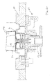
Figur 1 : einen Längsschnitt durch den Bodenbereich eines metallurgischen Gefäßes mit einer ersten Ausführungsform eines Gasspülsteins -
Figur 2a-d : Längsschnitte durch den Bodenbereich eines metallurgischen Gefäßes mit einer zweiten Ausführungsform eines Gasspülsteins,
wobei die einzelnen Montageschritte getrennt dargestellt sind. - In den Figuren sind gleiche oder gleich wirkende Bauteile mit gleichen Bezugsziffern dargestellt.
- Das Bezugszeichen 10 beschreibt einen kegelstumpfförmigen Gasspülstein mit einem äußeren Blechmantel 12 und einem Blechboden 14, der eine mittlere Öffnung 16 aufweist.
- In der dargestellten Montageposition verläuft oberhalb der Öffnung 16 ein feuerfester keramischer Körper 10k mit einem porösen Abschnitt 10p, durch den ein Gas in Pfeilrichtung G vom unteren, kalten Ende 10n des Gasspülsteins 10 zu dessen oberem (nicht dargestellten) heißen Ende 10o transportiert werden kann.
- Gegenüber dem porösen Abschnitt 10p verläuft um die Öffnung 16 herum ein Gasanschlussstutzen 20 für den Gasspülstein 10. Der Gasanschluss-stutzen 20 mit axialem Gaskanal 26 erstreckt sich in der dargestellten Montageposition von der Öffnung 16 nach unten.
- Der Gasanschlussstutzen 20 hat ein erstes Ende 20.1 im Abstand zum Gasspül-Element 10 und ein zweites Ende 20.2 benachbart dem Gasspül-Element 10. Der zweite Abschnitt 20.2 ist am Metallboden 14 angeschweißt (Schweißnaht 22).
- Im Bereich des zweiten Endes 20.2 weist der Gasanschlussstutzen 20 innen eine Querschnittsveränderung auf, wobei der Teil, der dem Gasspülstein 10 zugewandt ist, einen größeren Querschnitt hat. In diesem Abschnitt ist ein Körper 24 lose angeordnet. Ohne Gasdruck liegt er auf einer Schulter der beschriebenen Querschnittsverringerung des Gaskanals 26 auf. Unter Gasdruck hebt sich der Körper 24 von der Schulter ab und bewegt sich in Richtung auf den Gasspülstein 10. Ein oberhalb des Körpers 24 angeordneter Sicherungsstift 28 verhindert, dass der Körper 24 die Öffnung 16 absperrt.
- Am gegenüberliegenden ersten Ende 20.1 erweitert sich der Gaskanal 26 konusartig nach unten und nach außen. In diesen Teil ist ein zweites Ende 30.2 einer Gasziführ-Leitung 30 gasdicht eingesteckt. Dieses Ende 30.2 ist entsprechend kegelstumpfartig (düsenartig) gestaltet und sein verjüngtes Ende liegt oben. Das Ende 20.1 bildet die Dose, das Ende 30.2 den Stecker der Steckverbindung.
- In der Montageposition weist die Gaszuführ-Leitung 30 etwas unterhalb des ersten Endes 20.1 des Gasanschlussstutzens 20 außen eine Schulter 32 auf. Gegen die Schulter 32 liegt ein ringförmiger innerer Absatz 42 eines Sicherungselements 40 an, das ebenfalls rohrförmig ist. Das Sicherungselement 40 weist in dem Bereich oberhalb des Absatzes 42 ein Innengewinde 42i auf, welches auf ein korrespondierendes Außengewinde 20.1a des ebenfalls außen zylinderförmigen ersten Endes 20.1 des Gasanschlussstutzens 20 aufgeschraubt ist. Unterhalb des Absatzes 42 erstreckt sich das Sicherungselement 40 rohrförmig nach unten bis zu einem radial nach außen verlaufenden Rad 44 zur Arretierung.
- Bei diesem Ausführungsbeispiel wird die Anschlussverbindung von Gasanschlussstutzen 20 und Gaszuführ-Leitung 30 mit axial ineinander gesteckten Abschnitten 20.1, 30.2 gebildet, wobei die Steckverbindung über das Sicherungselement 40 gegen Lösen gesichert wird.
- Am Außenmantel 50 des zugehörigen metallurgischen Gefäßes ist eine Montagevorrichtung 60 über ein Gelenk 62 verschwenkbar befestigt, wobei
Figur 1 die Montageposition zeigt, bei der die Montagevorrichtung den Gasanschlussstutzen 20 sowie das zweite Ende 30.2 der Gaszuführ-Leitung 30 mit einem ringförmigen Element 64 übergreift. Das ringförmige Element 64 wird mit Hilfe eines Griffs 66 in der dargestellten Position gegenüber dem festen Außenmantel 50 fixiert. Dabei liegt das Element 64 gegen eine Hülse 68 an, die das zweite Ende 20.2 des Gasanschlussstutzens 20 umgibt. Die Hülse 68 ist Bestandteil der feuerfesten Auskleidung unterhalb des Gasspülelementes 10. Das erste Ende 20.1 des Gasanschlussstutzens 20 ragt nach unten über die Hülse 68 vor. - Die Montage ist einfach, weil die Montagevorrichtung 60 in die beschriebene Position geschwenkt werden kann, bevor die Gaszuführ-Leitung 30 auf den Gasanschlussstutzen 20 aufgesteckt und gesichert wird. Vor der gasdichten Verbindung der Teile 20,30 ist der Gasspülstein 10 sicher positioniert. Der Gasanschlussstutzen 20 der Anschlussverbindung ist präzise justiert, so dass die Steckverbindung mit der Gaszufüihr-Leitung 30 sehr einfach, genau und schnell erfolgen kann. Die Länge der Gaszuführ-Leitung 30 ist beliebig. Die Gaszuführ-Leitung 30 kann auch aus mehreren Teilabschnitten bestehen, die wiederum per Steckverbindung (oder anders) gasdicht miteinander verbunden werden können.
- Das gilt auch für die Ausführungsform nach
Figur 2 . Sie unterscheidet sich von der Variante gemäßFigur 1 vor allem in folgenden Merkmalen: - der Gasanschlussstutzen 20 ist nach Art eines Adapters gebildet, der am Metall-Boden 14 des Gasspülsteins 10 befestigt (hier: angeschweißt ist). Der Adapter steht nur 10 mm nach unten über den Boden 14 vor und ist an diesem Ende (20.1) ähnlich wie das erste Ende 20.1 des Gasanschlussstutzens 20 gemäß
Figur 1 gestaltet. Analog gilt dies für das zweite Ende 20.2 des Gasanschlussstutzens 20 beiFigur 2 . Mit anderen Worten: Beim Beispiel gemäßFigur 2 werden der Gasanschlussstutzen 20 und die anschließende Gaszuführ-Leitung 30 über eine Steckverbindung miteinander verbunden. - Die Gaszuführ-Litung 30 gemäß
Figur 2 ist zwischen den Enden (30.1, 30.2) nicht als Rohr (wie beiFigur 1 ) sondern als dickwandiger Zylinder gestaltet und erfüllt gleichzeitig die Funktion einer Durchbruchsicherung. Dazu ist der Gaskanal 26 zwischen zweitem Ende 30.2 und erstem Ende 30.1 nach Art einer Wendel (oder Spirale) gestaltet. Sollte Metallschmelze in den Gaskanal 26 eindringen würde diese radial nach außen (entlang der Wendel) geleitet, der Weg für die Schmelze also verlängert, um die Schmelze schneller abkühlen zu können, bis sie erstarrt. Dies ist vom Prinzip her bekannt und wird hier nicht näher beschrieben. - Das erste Ende 30.1 der Gaszuführ-Leitung 30 gemäß
Figur 2 ist analog zum ersten Ende 20.1 des Gasanschlussstutzens 20 gemäßFigur 1 gestaltet und dient zum Anschluss einer weiteren Gaszuführ-Leitung 70, die analog zur Gaszurühr-Leitung 30 gemäßFigur 1 gestaltet ist. - Das ringförmige Element 64 der Montagevorrichtung 60 liegt in der Montageposition direkt gegen die Unterseite des dickwandigen Teils der Gaszuführleitung 30 an.
- Die
Figuren 2a-d zeigen einzelne Montageschritte für diese Ausführungsform. Zuerst wird der Gasspülstein 10 (mit angeschlossenem Adapter 20) im Boden des metallurgischen Gefäßes eingebaut (Figur 2a ). - Die Montagevorrichtung 60 ist geöffnet.
- Dann wird die Gaszuführ-Leitung 30 einschließlich Durchbruchsicherung auf den Adapter 20 aufgesteckt und verschraubt (
Figur 2b ). Danach wird die Montagevorrichtung über beide Teile 20, 30 verschwenkt (Figur 2c ) und der Teil 30 gesichert. - Im letzten Schritt wird die weitere Gaszuführ-Leitung 70 mit ihrem oberen Ende 70.2 auf den unteren Abschnitt 30.1 der Gaszuführ-Leitung 30 aufgesteckt und über ein Schraub-Sicherungselement gesichert, analog wie bei den Enden 20.1, 30.2 (
Figur 2d ).
Claims (14)
- Gasspül-Element (10) für metallurgische Anwendungen mit folgenden Merkmalen:a) einem keramischen feuerfesten Körper (10k) mit einem ersten Ende (10u) und einem zweiten Ende (10o),b) das zweite Ende (10o) ist im Einbauzustand des Gasspül-Elements (10) in Kontakt mit einer Metallschmelze,c) das erste Ende (10u) wird außen von einem Metallmantel (12) bedeckt, der eine Öffnung (16) aufweist, an die sich ein Gasanschlussstutzen (20) anschließt,d) das Gasspül-Element (10), der Körper (10k) und der Gasanschlussstutzen (20) sind so ausgebildet, dass ein über den Gasanschlussstutzen (20) zugeführtes Behandlungsgas den Körper (10k) durchströmt und am zweiten Ende (10o) aus dem Körper (10k) austritt,e) der Gasanschlussstutzen (20) ist mit dem Metallmantel (12) verbunden und als Stecker oder Dose einer Steckverbindung ausgebildet, zur Verbindung mit einer korrespondierenden Dose oder einem korrespondierenden Stecker einer Gaszuführleitung (30).
- Gasspül-Element nach Anspruch 1, bei dem der Gasanschlussstutzen (20), ausgehend vom Anschlussbereich (22) zum Metallmantel (12), vom keramischen Körper (10k) weg verläuft.
- Gasspül-Element nach Anspruch 1, bei dem der Gasanschlussstutzen (20) , ausgehend vom Anschlussbereich (22) zum Metallmantel (12), in Richtung auf den keramischen Körper (10k) verläuft.
- Gasspül-Element nach Anspruch 1, bei dem der als Stecker ausgebildete Gasanschlussstutzen (20) außen eine der folgenden geometrischen Formen aufweist: Kegel, Kegelstumpf, Prisma .
- Gasspül-Element nach Anspruch 1, bei dem der als Dose ausgebildete Gasanschlussstutzen (20) innen eine der folgenden geometrischen Formen aufweist: negativer Kegel, negativer Kegelstumpf, negatives Prisma .
- Gasspül-Element nach Anspruch 1, bei dem der Gasanschlussstutzen (20) mit einer Durchbruchsicherung gegen eindringende Metallschmelze ausgebildet ist.
- Gasspül-Element nach Anspruch 1, bei dem der Gasanschlussstutzen (20) mit einem Rückschlagventil (26,28) ausgebildet ist.
- Gasspül-Element nach Anspruch 1, dessen Gasanschlussstutzen (20) eine Länge, in Strömungsrichtung (G) des zugeführten Gases, kleiner 20 cm aufweist.
- Gasspül-Element nach Anspruch 1, deren Gasanschlussstutzen (20) an seinem freien Ende (20.1) ein Außengewinde aufweist.
- Gaszuführleitung (30) für ein Gasspül-Element nach einem der Ansprüche 1-9, mit einem, ersten Ende (30.1) und einem zweiten Ende (30.2) zum Anschluss an den Gasanschlussstutzen (20) des Gasspül-Elements, wobei das zweite Ende (30.2) korrespondierend zum Gasanschlussstutzen (20) als Stecker oder Dose der Steckverbindung zwischen dem Gasanschlussstutzen (20) und dem zweitem Ende (30.2) der Gaszuführleitung (30) ausgebildet ist.
- Gaszuführleitung nach Anspruch 10, bei der das ersten Ende (30.1) als Dose ausgebildet ist, wenn das zweite Ende (30.2) als Stecker ausgebildet ist.
- Gaszuführleitung nach Anspruch 10, bei der das erste Ende (30.1) zum Anschluss an eine weitere Gaszuführleitung (70) ausgebildet ist.
- Gaszuführleitung nach Anspruch 10, bei der das erste Ende (30.1) zum Anschluss an eine Gasquelle ausgebildet ist.
- Gaszuführleitung nach Anspruch 10, bei der das zweite Ende (30.2) eine nach innen weisende Stufe (42) und ein Innengewinde (40i) aufweist, das sich zwischen der Stufe (42) und einem freiem Rand des zweiten Endes (30.2) erstreckt.
Priority Applications (22)
| Application Number | Priority Date | Filing Date | Title |
|---|---|---|---|
| EP16181865.3A EP3106813A1 (de) | 2012-08-27 | 2012-08-27 | Gasspül-element und zugehörige gaszuführ-leitung |
| EP12181902.3A EP2703761B1 (de) | 2012-08-27 | 2012-08-27 | Gasspül-Element mit zugehöriger Gaszuführ-Leitung |
| HUE12181902A HUE029621T2 (en) | 2012-08-27 | 2012-08-27 | Gas inlet element with associated gas supply line |
| PL12181902.3T PL2703761T3 (pl) | 2012-08-27 | 2012-08-27 | Element do przepłukiwania gazem z należącym do niego przewodem doprowadzającym gaz |
| ES12181902.3T ES2592174T3 (es) | 2012-08-27 | 2012-08-27 | Elemento de purga de gas con conducto de suministro de gas correspondiente |
| UAA201413414A UA111663C2 (uk) | 2012-08-27 | 2013-07-08 | Газопродувний елемент і співвіднесений газопідвідний трубопровід |
| TW102125226A TWI558485B (zh) | 2012-08-27 | 2013-07-15 | 氣體沖灌元件及對應的氣體供應線 |
| JP2015527843A JP5982574B2 (ja) | 2012-08-27 | 2013-08-07 | ガスパージ要素および対応するガス供給ライン |
| BR112015000090-8A BR112015000090B1 (pt) | 2012-08-27 | 2013-08-07 | dispositivo de purga de gás |
| EA201401263A EA029105B1 (ru) | 2012-08-27 | 2013-08-07 | Газопродувочное устройство для металлургических применений |
| PE2014002454A PE20150152A1 (es) | 2012-08-27 | 2013-08-07 | Elemento de purga de gas y linea de alimentacion de gas asociada |
| KR1020147035060A KR101687091B1 (ko) | 2012-08-27 | 2013-08-07 | 가스 정화 요소 및 관련 가스 공급 라인 |
| CN201380036101.8A CN104412058B (zh) | 2012-08-27 | 2013-08-07 | 吹气元件和相关的气体输送管路 |
| MX2014012134A MX362688B (es) | 2012-08-27 | 2013-08-07 | Elemento de purga de gas y línea de alimentación de gas asociada. |
| CA2876461A CA2876461C (en) | 2012-08-27 | 2013-08-07 | Gas purging element and corresponding gas supply line |
| PCT/EP2013/066531 WO2014032923A2 (de) | 2012-08-27 | 2013-08-07 | Gasspül-element und zugehörige gaszuführ-leitung |
| US14/411,865 US9683272B2 (en) | 2012-08-27 | 2013-08-07 | Gas purging element and associated gas feed line |
| IL236502A IL236502B (en) | 2012-08-27 | 2014-12-28 | Gas purification agent and compatible gas supply pipe |
| CL2014003639A CL2014003639A1 (es) | 2012-08-27 | 2014-12-31 | Elemento de purga de gas para aplicaciones metalurgicas con las siguientes caracteristicas, con un cuerpo de ceramica a prueba de fuego con un primer extremo y un segundo extremo; un tubo de suministro de gas para un elemento de purga de gas. |
| SA515360061A SA515360061B1 (ar) | 2012-08-27 | 2015-02-23 | عنصر تطهير غـاز وخط تغذية غـاز ذي صلة |
| ZA2015/01967A ZA201501967B (en) | 2012-08-27 | 2015-03-23 | Gas purging element and associated gas feed line |
| US15/604,151 US20170327914A1 (en) | 2012-08-27 | 2017-05-24 | Gas purging element and corresponding gas supply line |
Applications Claiming Priority (1)
| Application Number | Priority Date | Filing Date | Title |
|---|---|---|---|
| EP12181902.3A EP2703761B1 (de) | 2012-08-27 | 2012-08-27 | Gasspül-Element mit zugehöriger Gaszuführ-Leitung |
Related Child Applications (1)
| Application Number | Title | Priority Date | Filing Date |
|---|---|---|---|
| EP16181865.3A Division EP3106813A1 (de) | 2012-08-27 | 2012-08-27 | Gasspül-element und zugehörige gaszuführ-leitung |
Publications (2)
| Publication Number | Publication Date |
|---|---|
| EP2703761A1 true EP2703761A1 (de) | 2014-03-05 |
| EP2703761B1 EP2703761B1 (de) | 2016-08-17 |
Family
ID=46799073
Family Applications (2)
| Application Number | Title | Priority Date | Filing Date |
|---|---|---|---|
| EP12181902.3A Active EP2703761B1 (de) | 2012-08-27 | 2012-08-27 | Gasspül-Element mit zugehöriger Gaszuführ-Leitung |
| EP16181865.3A Withdrawn EP3106813A1 (de) | 2012-08-27 | 2012-08-27 | Gasspül-element und zugehörige gaszuführ-leitung |
Family Applications After (1)
| Application Number | Title | Priority Date | Filing Date |
|---|---|---|---|
| EP16181865.3A Withdrawn EP3106813A1 (de) | 2012-08-27 | 2012-08-27 | Gasspül-element und zugehörige gaszuführ-leitung |
Country Status (20)
| Country | Link |
|---|---|
| US (2) | US9683272B2 (de) |
| EP (2) | EP2703761B1 (de) |
| JP (1) | JP5982574B2 (de) |
| KR (1) | KR101687091B1 (de) |
| CN (1) | CN104412058B (de) |
| BR (1) | BR112015000090B1 (de) |
| CA (1) | CA2876461C (de) |
| CL (1) | CL2014003639A1 (de) |
| EA (1) | EA029105B1 (de) |
| ES (1) | ES2592174T3 (de) |
| HU (1) | HUE029621T2 (de) |
| IL (1) | IL236502B (de) |
| MX (1) | MX362688B (de) |
| PE (1) | PE20150152A1 (de) |
| PL (1) | PL2703761T3 (de) |
| SA (1) | SA515360061B1 (de) |
| TW (1) | TWI558485B (de) |
| UA (1) | UA111663C2 (de) |
| WO (1) | WO2014032923A2 (de) |
| ZA (1) | ZA201501967B (de) |
Cited By (1)
| Publication number | Priority date | Publication date | Assignee | Title |
|---|---|---|---|---|
| CN109777921A (zh) * | 2017-11-14 | 2019-05-21 | 党祎贤 | 一种钢包吹氩自动对接机构 |
Families Citing this family (3)
| Publication number | Priority date | Publication date | Assignee | Title |
|---|---|---|---|---|
| EP2703761B1 (de) * | 2012-08-27 | 2016-08-17 | Refractory Intellectual Property GmbH & Co. KG | Gasspül-Element mit zugehöriger Gaszuführ-Leitung |
| EP3689496B1 (de) * | 2017-09-28 | 2022-10-26 | Krosakiharima Corporation | Struktur einer gaseinführöffnungsdose |
| RU2769101C1 (ru) | 2018-01-29 | 2022-03-28 | Рефрактори Интеллектуал Проперти Гмбх & Ко. Кг | Газопродувочная пробка, газопродувочная система, способ исследования газопродувочной пробки и способ продувки расплавленного металла |
Citations (8)
| Publication number | Priority date | Publication date | Assignee | Title |
|---|---|---|---|---|
| US3834685A (en) * | 1973-09-24 | 1974-09-10 | Allegheny Ludlum Ind Inc | Apparatus for injecting fluids into molten metals |
| AT365958B (de) * | 1980-06-30 | 1982-02-25 | Voest Alpine Ag | Metallurgisches gefaess |
| EP0148337A1 (de) | 1983-11-17 | 1985-07-17 | Radex Deutschland Aktiengesellschaft für feuerfeste Erzeugnisse | Gasspülstein für metallurgische Gefässe |
| EP0234852A1 (de) * | 1986-02-20 | 1987-09-02 | Injectall Limited | Einblasen von Stoffen in Flüssigkeiten hoher Temperatur |
| DE3833502C2 (de) | 1988-10-01 | 1990-10-04 | Didier-Werke Ag, 6200 Wiesbaden, De | |
| US5112029A (en) * | 1991-07-22 | 1992-05-12 | Instituo Mexicano De Investigaciones Siderurgicas | Quick fluid injection assembly replacement in metallurgical reacters |
| WO2005107979A1 (de) * | 2004-05-05 | 2005-11-17 | Stefan Munding | Gasspülvorrichtung |
| WO2011118477A1 (ja) * | 2010-03-23 | 2011-09-29 | 黒崎播磨株式会社 | ガス吹き込み用プラグの設置構造 |
Family Cites Families (12)
| Publication number | Priority date | Publication date | Assignee | Title |
|---|---|---|---|---|
| FR2451945A1 (fr) * | 1979-03-19 | 1980-10-17 | Est Aciers Fins | Tuyere de brassage de bain de metal liquide |
| US4632367A (en) * | 1984-10-19 | 1986-12-30 | Labate Michael D | Device for introducing gas into molten metal |
| US4725047A (en) * | 1985-08-26 | 1988-02-16 | Labate M D | Device for introducing gas into molten metal |
| DE3833504A1 (de) * | 1988-10-01 | 1990-04-05 | Didier Werke Ag | Gasspueleinrichtung |
| CA2014999C (en) * | 1989-04-24 | 1999-09-07 | Kenneth William Bates | Gas injector |
| DE4029024C2 (de) * | 1990-09-13 | 1999-10-28 | Beda Oxygentech Armatur | Spülanschlußkupplung |
| DE4121329C2 (de) * | 1991-06-28 | 1995-09-07 | Veitsch Radex Ag | Gasspülstein |
| DE19948848C1 (de) * | 1999-10-08 | 2000-07-13 | Dolomitwerke Gmbh | Gasspülstein für metallurgische Gefäße |
| KR200417535Y1 (ko) * | 2006-03-21 | 2006-05-30 | 조선내화 주식회사 | 래들용 버블링플러그 고정장치 |
| CN201221636Y (zh) * | 2008-06-05 | 2009-04-15 | 钟伯华 | 瓦斯阀座 |
| JP2010189687A (ja) * | 2009-02-17 | 2010-09-02 | Tokyo Yogyo Co Ltd | ガス吹き込みプラグ |
| EP2703761B1 (de) * | 2012-08-27 | 2016-08-17 | Refractory Intellectual Property GmbH & Co. KG | Gasspül-Element mit zugehöriger Gaszuführ-Leitung |
-
2012
- 2012-08-27 EP EP12181902.3A patent/EP2703761B1/de active Active
- 2012-08-27 ES ES12181902.3T patent/ES2592174T3/es active Active
- 2012-08-27 PL PL12181902.3T patent/PL2703761T3/pl unknown
- 2012-08-27 EP EP16181865.3A patent/EP3106813A1/de not_active Withdrawn
- 2012-08-27 HU HUE12181902A patent/HUE029621T2/en unknown
-
2013
- 2013-07-08 UA UAA201413414A patent/UA111663C2/uk unknown
- 2013-07-15 TW TW102125226A patent/TWI558485B/zh active
- 2013-08-07 PE PE2014002454A patent/PE20150152A1/es not_active Application Discontinuation
- 2013-08-07 CN CN201380036101.8A patent/CN104412058B/zh active Active
- 2013-08-07 MX MX2014012134A patent/MX362688B/es active IP Right Grant
- 2013-08-07 WO PCT/EP2013/066531 patent/WO2014032923A2/de active Application Filing
- 2013-08-07 BR BR112015000090-8A patent/BR112015000090B1/pt active IP Right Grant
- 2013-08-07 EA EA201401263A patent/EA029105B1/ru not_active IP Right Cessation
- 2013-08-07 US US14/411,865 patent/US9683272B2/en active Active
- 2013-08-07 CA CA2876461A patent/CA2876461C/en active Active
- 2013-08-07 KR KR1020147035060A patent/KR101687091B1/ko active IP Right Grant
- 2013-08-07 JP JP2015527843A patent/JP5982574B2/ja active Active
-
2014
- 2014-12-28 IL IL236502A patent/IL236502B/en not_active IP Right Cessation
- 2014-12-31 CL CL2014003639A patent/CL2014003639A1/es unknown
-
2015
- 2015-02-23 SA SA515360061A patent/SA515360061B1/ar unknown
- 2015-03-23 ZA ZA2015/01967A patent/ZA201501967B/en unknown
-
2017
- 2017-05-24 US US15/604,151 patent/US20170327914A1/en not_active Abandoned
Patent Citations (8)
| Publication number | Priority date | Publication date | Assignee | Title |
|---|---|---|---|---|
| US3834685A (en) * | 1973-09-24 | 1974-09-10 | Allegheny Ludlum Ind Inc | Apparatus for injecting fluids into molten metals |
| AT365958B (de) * | 1980-06-30 | 1982-02-25 | Voest Alpine Ag | Metallurgisches gefaess |
| EP0148337A1 (de) | 1983-11-17 | 1985-07-17 | Radex Deutschland Aktiengesellschaft für feuerfeste Erzeugnisse | Gasspülstein für metallurgische Gefässe |
| EP0234852A1 (de) * | 1986-02-20 | 1987-09-02 | Injectall Limited | Einblasen von Stoffen in Flüssigkeiten hoher Temperatur |
| DE3833502C2 (de) | 1988-10-01 | 1990-10-04 | Didier-Werke Ag, 6200 Wiesbaden, De | |
| US5112029A (en) * | 1991-07-22 | 1992-05-12 | Instituo Mexicano De Investigaciones Siderurgicas | Quick fluid injection assembly replacement in metallurgical reacters |
| WO2005107979A1 (de) * | 2004-05-05 | 2005-11-17 | Stefan Munding | Gasspülvorrichtung |
| WO2011118477A1 (ja) * | 2010-03-23 | 2011-09-29 | 黒崎播磨株式会社 | ガス吹き込み用プラグの設置構造 |
Cited By (1)
| Publication number | Priority date | Publication date | Assignee | Title |
|---|---|---|---|---|
| CN109777921A (zh) * | 2017-11-14 | 2019-05-21 | 党祎贤 | 一种钢包吹氩自动对接机构 |
Also Published As
| Publication number | Publication date |
|---|---|
| EP3106813A1 (de) | 2016-12-21 |
| ES2592174T3 (es) | 2016-11-28 |
| JP2015531828A (ja) | 2015-11-05 |
| EA029105B1 (ru) | 2018-02-28 |
| PE20150152A1 (es) | 2015-02-07 |
| BR112015000090A2 (pt) | 2017-06-27 |
| CL2014003639A1 (es) | 2015-07-31 |
| WO2014032923A2 (de) | 2014-03-06 |
| EP2703761B1 (de) | 2016-08-17 |
| CA2876461C (en) | 2017-07-18 |
| TWI558485B (zh) | 2016-11-21 |
| MX2014012134A (es) | 2015-03-05 |
| KR101687091B1 (ko) | 2016-12-15 |
| CN104412058A (zh) | 2015-03-11 |
| CA2876461A1 (en) | 2014-03-06 |
| KR20150030204A (ko) | 2015-03-19 |
| ZA201501967B (en) | 2016-01-27 |
| PL2703761T3 (pl) | 2016-12-30 |
| MX362688B (es) | 2019-02-01 |
| IL236502B (en) | 2018-03-29 |
| US9683272B2 (en) | 2017-06-20 |
| HUE029621T2 (en) | 2017-03-28 |
| JP5982574B2 (ja) | 2016-08-31 |
| BR112015000090B1 (pt) | 2021-01-19 |
| CN104412058B (zh) | 2016-08-17 |
| TW201408400A (zh) | 2014-03-01 |
| IL236502A0 (en) | 2015-02-26 |
| EA201401263A1 (ru) | 2015-07-30 |
| WO2014032923A3 (de) | 2014-06-26 |
| US20150184265A1 (en) | 2015-07-02 |
| US20170327914A1 (en) | 2017-11-16 |
| SA515360061B1 (ar) | 2017-04-16 |
| UA111663C2 (uk) | 2016-05-25 |
Similar Documents
| Publication | Publication Date | Title |
|---|---|---|
| DE112011105227B4 (de) | Filtervorrichtung | |
| DE2728887C2 (de) | Anschlußvorrichtung | |
| EP3379129B1 (de) | Anschlussverbinder | |
| EP1805447A1 (de) | Zugfeste steckkupplung | |
| EP2703761B1 (de) | Gasspül-Element mit zugehöriger Gaszuführ-Leitung | |
| EP3173675A1 (de) | Schlauchanschluss | |
| EP2047110B1 (de) | Fluidtechnische vorrichtung | |
| DE112020002258T5 (de) | Kopf für Druckgasbehälter | |
| EP2496871B1 (de) | Kopplungssystem, verteiler, rohrsystem und rohrversetzsystem | |
| EP2743579A1 (de) | Brennerspitze und Brenner | |
| CH651909A5 (de) | Vorrichtung zum verbinden eines kunststoffrohres mit einem rohrstutzen. | |
| DE112014000513B4 (de) | Durchflussratensteuervorrichtung | |
| EP3467382B1 (de) | Kraftstoffanschlusseinheit | |
| EP2208676B1 (de) | Rohrklemme | |
| EP3526507B1 (de) | Verbinder und verbinderbaugruppe und verfahren zur herstellung eines verbinders | |
| EP2893992B1 (de) | Gasspül-Element und zugehöriges Gasanschluss-Element | |
| WO2018210622A1 (de) | Anschlussvorrichtung | |
| EP1549873B1 (de) | Aufnahmeteil einer fluid-steckverbindung | |
| EP1384867A1 (de) | Vorrichtung zum Abdichten einer Abgasrohrleitung | |
| DE3702561C2 (de) | ||
| DE102014217410B4 (de) | Fluidleitende Verbindungsanordnung sowie Klemmring | |
| DE19727346C2 (de) | Demontierbare gasdichte Durchführung in ein Prozessrohr | |
| EP3023173B1 (de) | Befestigungsvorrichtung für einen zylinderförmigen keramischen Hohlkörper und feuerfester keramischer Gasspülstein mit einer solchen Befestigungsvorrichtung | |
| WO2017148493A1 (de) | Schmelzeführender verbindungsadapter sowie darauf bezogene schmelzeverarbeitungsanlage | |
| DE202017100431U1 (de) | Brennerdüsenkappe für eine Brennstofflanze |
Legal Events
| Date | Code | Title | Description |
|---|---|---|---|
| 17P | Request for examination filed |
Effective date: 20131011 |
|
| AK | Designated contracting states |
Kind code of ref document: A1 Designated state(s): AL AT BE BG CH CY CZ DE DK EE ES FI FR GB GR HR HU IE IS IT LI LT LU LV MC MK MT NL NO PL PT RO RS SE SI SK SM TR |
|
| AX | Request for extension of the european patent |
Extension state: BA ME |
|
| PUAI | Public reference made under article 153(3) epc to a published international application that has entered the european phase |
Free format text: ORIGINAL CODE: 0009012 |
|
| 17Q | First examination report despatched |
Effective date: 20141211 |
|
| GRAP | Despatch of communication of intention to grant a patent |
Free format text: ORIGINAL CODE: EPIDOSNIGR1 |
|
| INTG | Intention to grant announced |
Effective date: 20160527 |
|
| GRAS | Grant fee paid |
Free format text: ORIGINAL CODE: EPIDOSNIGR3 |
|
| GRAA | (expected) grant |
Free format text: ORIGINAL CODE: 0009210 |
|
| AK | Designated contracting states |
Kind code of ref document: B1 Designated state(s): AL AT BE BG CH CY CZ DE DK EE ES FI FR GB GR HR HU IE IS IT LI LT LU LV MC MK MT NL NO PL PT RO RS SE SI SK SM TR |
|
| REG | Reference to a national code |
Ref country code: GB Ref legal event code: FG4D Free format text: NOT ENGLISH |
|
| REG | Reference to a national code |
Ref country code: CH Ref legal event code: EP |
|
| REG | Reference to a national code |
Ref country code: IE Ref legal event code: FG4D Free format text: LANGUAGE OF EP DOCUMENT: GERMAN |
|
| REG | Reference to a national code |
Ref country code: AT Ref legal event code: REF Ref document number: 821510 Country of ref document: AT Kind code of ref document: T Effective date: 20160915 |
|
| REG | Reference to a national code |
Ref country code: SE Ref legal event code: TRGR |
|
| REG | Reference to a national code |
Ref country code: NL Ref legal event code: FP Ref country code: RO Ref legal event code: EPE |
|
| REG | Reference to a national code |
Ref country code: DE Ref legal event code: R096 Ref document number: 502012007954 Country of ref document: DE Ref country code: FR Ref legal event code: PLFP Year of fee payment: 5 |
|
| REG | Reference to a national code |
Ref country code: ES Ref legal event code: FG2A Ref document number: 2592174 Country of ref document: ES Kind code of ref document: T3 Effective date: 20161128 |
|
| REG | Reference to a national code |
Ref country code: LT Ref legal event code: MG4D |
|
| PG25 | Lapsed in a contracting state [announced via postgrant information from national office to epo] |
Ref country code: LT Free format text: LAPSE BECAUSE OF FAILURE TO SUBMIT A TRANSLATION OF THE DESCRIPTION OR TO PAY THE FEE WITHIN THE PRESCRIBED TIME-LIMIT Effective date: 20160817 Ref country code: RS Free format text: LAPSE BECAUSE OF FAILURE TO SUBMIT A TRANSLATION OF THE DESCRIPTION OR TO PAY THE FEE WITHIN THE PRESCRIBED TIME-LIMIT Effective date: 20160817 Ref country code: HR Free format text: LAPSE BECAUSE OF FAILURE TO SUBMIT A TRANSLATION OF THE DESCRIPTION OR TO PAY THE FEE WITHIN THE PRESCRIBED TIME-LIMIT Effective date: 20160817 Ref country code: NO Free format text: LAPSE BECAUSE OF FAILURE TO SUBMIT A TRANSLATION OF THE DESCRIPTION OR TO PAY THE FEE WITHIN THE PRESCRIBED TIME-LIMIT Effective date: 20161117 |
|
| REG | Reference to a national code |
Ref country code: SK Ref legal event code: T3 Ref document number: E 22274 Country of ref document: SK |
|
| PG25 | Lapsed in a contracting state [announced via postgrant information from national office to epo] |
Ref country code: GR Free format text: LAPSE BECAUSE OF FAILURE TO SUBMIT A TRANSLATION OF THE DESCRIPTION OR TO PAY THE FEE WITHIN THE PRESCRIBED TIME-LIMIT Effective date: 20161118 Ref country code: PT Free format text: LAPSE BECAUSE OF FAILURE TO SUBMIT A TRANSLATION OF THE DESCRIPTION OR TO PAY THE FEE WITHIN THE PRESCRIBED TIME-LIMIT Effective date: 20161219 Ref country code: LV Free format text: LAPSE BECAUSE OF FAILURE TO SUBMIT A TRANSLATION OF THE DESCRIPTION OR TO PAY THE FEE WITHIN THE PRESCRIBED TIME-LIMIT Effective date: 20160817 |
|
| REG | Reference to a national code |
Ref country code: HU Ref legal event code: AG4A Ref document number: E029621 Country of ref document: HU |
|
| PG25 | Lapsed in a contracting state [announced via postgrant information from national office to epo] |
Ref country code: EE Free format text: LAPSE BECAUSE OF FAILURE TO SUBMIT A TRANSLATION OF THE DESCRIPTION OR TO PAY THE FEE WITHIN THE PRESCRIBED TIME-LIMIT Effective date: 20160817 |
|
| REG | Reference to a national code |
Ref country code: DE Ref legal event code: R097 Ref document number: 502012007954 Country of ref document: DE |
|
| PG25 | Lapsed in a contracting state [announced via postgrant information from national office to epo] |
Ref country code: DK Free format text: LAPSE BECAUSE OF FAILURE TO SUBMIT A TRANSLATION OF THE DESCRIPTION OR TO PAY THE FEE WITHIN THE PRESCRIBED TIME-LIMIT Effective date: 20160817 Ref country code: SM Free format text: LAPSE BECAUSE OF FAILURE TO SUBMIT A TRANSLATION OF THE DESCRIPTION OR TO PAY THE FEE WITHIN THE PRESCRIBED TIME-LIMIT Effective date: 20160817 Ref country code: BG Free format text: LAPSE BECAUSE OF FAILURE TO SUBMIT A TRANSLATION OF THE DESCRIPTION OR TO PAY THE FEE WITHIN THE PRESCRIBED TIME-LIMIT Effective date: 20161117 |
|
| REG | Reference to a national code |
Ref country code: IE Ref legal event code: MM4A |
|
| PLBE | No opposition filed within time limit |
Free format text: ORIGINAL CODE: 0009261 |
|
| STAA | Information on the status of an ep patent application or granted ep patent |
Free format text: STATUS: NO OPPOSITION FILED WITHIN TIME LIMIT |
|
| PG25 | Lapsed in a contracting state [announced via postgrant information from national office to epo] |
Ref country code: MC Free format text: LAPSE BECAUSE OF FAILURE TO SUBMIT A TRANSLATION OF THE DESCRIPTION OR TO PAY THE FEE WITHIN THE PRESCRIBED TIME-LIMIT Effective date: 20160817 |
|
| 26N | No opposition filed |
Effective date: 20170518 |
|
| PG25 | Lapsed in a contracting state [announced via postgrant information from national office to epo] |
Ref country code: IE Free format text: LAPSE BECAUSE OF NON-PAYMENT OF DUE FEES Effective date: 20160827 |
|
| REG | Reference to a national code |
Ref country code: FR Ref legal event code: PLFP Year of fee payment: 6 |
|
| PG25 | Lapsed in a contracting state [announced via postgrant information from national office to epo] |
Ref country code: SI Free format text: LAPSE BECAUSE OF FAILURE TO SUBMIT A TRANSLATION OF THE DESCRIPTION OR TO PAY THE FEE WITHIN THE PRESCRIBED TIME-LIMIT Effective date: 20160817 |
|
| PGFP | Annual fee paid to national office [announced via postgrant information from national office to epo] |
Ref country code: GB Payment date: 20170727 Year of fee payment: 14 |
|
| PGFP | Annual fee paid to national office [announced via postgrant information from national office to epo] |
Ref country code: SK Payment date: 20170818 Year of fee payment: 6 |
|
| PG25 | Lapsed in a contracting state [announced via postgrant information from national office to epo] |
Ref country code: CY Free format text: LAPSE BECAUSE OF FAILURE TO SUBMIT A TRANSLATION OF THE DESCRIPTION OR TO PAY THE FEE WITHIN THE PRESCRIBED TIME-LIMIT Effective date: 20160817 |
|
| PG25 | Lapsed in a contracting state [announced via postgrant information from national office to epo] |
Ref country code: MT Free format text: LAPSE BECAUSE OF FAILURE TO SUBMIT A TRANSLATION OF THE DESCRIPTION OR TO PAY THE FEE WITHIN THE PRESCRIBED TIME-LIMIT Effective date: 20160817 Ref country code: MK Free format text: LAPSE BECAUSE OF FAILURE TO SUBMIT A TRANSLATION OF THE DESCRIPTION OR TO PAY THE FEE WITHIN THE PRESCRIBED TIME-LIMIT Effective date: 20160817 Ref country code: IS Free format text: LAPSE BECAUSE OF FAILURE TO SUBMIT A TRANSLATION OF THE DESCRIPTION OR TO PAY THE FEE WITHIN THE PRESCRIBED TIME-LIMIT Effective date: 20160817 |
|
| REG | Reference to a national code |
Ref country code: FR Ref legal event code: PLFP Year of fee payment: 7 |
|
| PG25 | Lapsed in a contracting state [announced via postgrant information from national office to epo] |
Ref country code: AL Free format text: LAPSE BECAUSE OF FAILURE TO SUBMIT A TRANSLATION OF THE DESCRIPTION OR TO PAY THE FEE WITHIN THE PRESCRIBED TIME-LIMIT Effective date: 20160817 |
|
| REG | Reference to a national code |
Ref country code: NL Ref legal event code: MM Effective date: 20180901 |
|
| REG | Reference to a national code |
Ref country code: SK Ref legal event code: MM4A Ref document number: E 22274 Country of ref document: SK Effective date: 20180827 |
|
| PG25 | Lapsed in a contracting state [announced via postgrant information from national office to epo] |
Ref country code: SK Free format text: LAPSE BECAUSE OF NON-PAYMENT OF DUE FEES Effective date: 20180827 |
|
| PG25 | Lapsed in a contracting state [announced via postgrant information from national office to epo] |
Ref country code: NL Free format text: LAPSE BECAUSE OF NON-PAYMENT OF DUE FEES Effective date: 20180901 |
|
| PGFP | Annual fee paid to national office [announced via postgrant information from national office to epo] |
Ref country code: HU Payment date: 20210821 Year of fee payment: 10 |
|
| PG25 | Lapsed in a contracting state [announced via postgrant information from national office to epo] |
Ref country code: HU Free format text: LAPSE BECAUSE OF NON-PAYMENT OF DUE FEES Effective date: 20220828 |
|
| PGFP | Annual fee paid to national office [announced via postgrant information from national office to epo] |
Ref country code: LU Payment date: 20230821 Year of fee payment: 12 |
|
| PGFP | Annual fee paid to national office [announced via postgrant information from national office to epo] |
Ref country code: TR Payment date: 20230825 Year of fee payment: 12 Ref country code: RO Payment date: 20230822 Year of fee payment: 12 Ref country code: IT Payment date: 20230825 Year of fee payment: 12 Ref country code: FI Payment date: 20230821 Year of fee payment: 12 Ref country code: CZ Payment date: 20230818 Year of fee payment: 12 Ref country code: CH Payment date: 20230902 Year of fee payment: 12 Ref country code: AT Payment date: 20230822 Year of fee payment: 12 |
|
| PGFP | Annual fee paid to national office [announced via postgrant information from national office to epo] |
Ref country code: SE Payment date: 20230821 Year of fee payment: 12 Ref country code: PL Payment date: 20230818 Year of fee payment: 12 Ref country code: FR Payment date: 20230824 Year of fee payment: 12 Ref country code: DE Payment date: 20230821 Year of fee payment: 12 Ref country code: BE Payment date: 20230821 Year of fee payment: 12 |
|
| PGFP | Annual fee paid to national office [announced via postgrant information from national office to epo] |
Ref country code: ES Payment date: 20231027 Year of fee payment: 12 |