EP1549873B1 - Aufnahmeteil einer fluid-steckverbindung - Google Patents
Aufnahmeteil einer fluid-steckverbindung Download PDFInfo
- Publication number
- EP1549873B1 EP1549873B1 EP03769345A EP03769345A EP1549873B1 EP 1549873 B1 EP1549873 B1 EP 1549873B1 EP 03769345 A EP03769345 A EP 03769345A EP 03769345 A EP03769345 A EP 03769345A EP 1549873 B1 EP1549873 B1 EP 1549873B1
- Authority
- EP
- European Patent Office
- Prior art keywords
- plug
- retaining ring
- receiving part
- opening
- latching
- Prior art date
- Legal status (The legal status is an assumption and is not a legal conclusion. Google has not performed a legal analysis and makes no representation as to the accuracy of the status listed.)
- Expired - Lifetime
Links
- 239000012530 fluid Substances 0.000 title claims abstract description 5
- 238000003780 insertion Methods 0.000 claims abstract description 12
- 230000037431 insertion Effects 0.000 claims abstract description 12
- 238000000465 moulding Methods 0.000 claims description 2
- 238000007789 sealing Methods 0.000 abstract description 2
- 238000000034 method Methods 0.000 description 3
- 210000002105 tongue Anatomy 0.000 description 3
- 238000004090 dissolution Methods 0.000 description 2
- 238000013459 approach Methods 0.000 description 1
- 230000004323 axial length Effects 0.000 description 1
- 230000000903 blocking effect Effects 0.000 description 1
- 230000001419 dependent effect Effects 0.000 description 1
- 230000005489 elastic deformation Effects 0.000 description 1
- 239000007789 gas Substances 0.000 description 1
- 239000007788 liquid Substances 0.000 description 1
- 238000004519 manufacturing process Methods 0.000 description 1
- 230000002093 peripheral effect Effects 0.000 description 1
- 238000011144 upstream manufacturing Methods 0.000 description 1
Images

Classifications
-
- F—MECHANICAL ENGINEERING; LIGHTING; HEATING; WEAPONS; BLASTING
- F16—ENGINEERING ELEMENTS AND UNITS; GENERAL MEASURES FOR PRODUCING AND MAINTAINING EFFECTIVE FUNCTIONING OF MACHINES OR INSTALLATIONS; THERMAL INSULATION IN GENERAL
- F16L—PIPES; JOINTS OR FITTINGS FOR PIPES; SUPPORTS FOR PIPES, CABLES OR PROTECTIVE TUBING; MEANS FOR THERMAL INSULATION IN GENERAL
- F16L37/00—Couplings of the quick-acting type
- F16L37/008—Couplings of the quick-acting type for branching pipes; for joining pipes to walls
-
- F—MECHANICAL ENGINEERING; LIGHTING; HEATING; WEAPONS; BLASTING
- F16—ENGINEERING ELEMENTS AND UNITS; GENERAL MEASURES FOR PRODUCING AND MAINTAINING EFFECTIVE FUNCTIONING OF MACHINES OR INSTALLATIONS; THERMAL INSULATION IN GENERAL
- F16L—PIPES; JOINTS OR FITTINGS FOR PIPES; SUPPORTS FOR PIPES, CABLES OR PROTECTIVE TUBING; MEANS FOR THERMAL INSULATION IN GENERAL
- F16L37/00—Couplings of the quick-acting type
- F16L37/08—Couplings of the quick-acting type in which the connection between abutting or axially overlapping ends is maintained by locking members
- F16L37/084—Couplings of the quick-acting type in which the connection between abutting or axially overlapping ends is maintained by locking members combined with automatic locking
- F16L37/098—Couplings of the quick-acting type in which the connection between abutting or axially overlapping ends is maintained by locking members combined with automatic locking by means of flexible hooks
- F16L37/0982—Couplings of the quick-acting type in which the connection between abutting or axially overlapping ends is maintained by locking members combined with automatic locking by means of flexible hooks with a separate member for releasing the coupling
-
- F—MECHANICAL ENGINEERING; LIGHTING; HEATING; WEAPONS; BLASTING
- F16—ENGINEERING ELEMENTS AND UNITS; GENERAL MEASURES FOR PRODUCING AND MAINTAINING EFFECTIVE FUNCTIONING OF MACHINES OR INSTALLATIONS; THERMAL INSULATION IN GENERAL
- F16L—PIPES; JOINTS OR FITTINGS FOR PIPES; SUPPORTS FOR PIPES, CABLES OR PROTECTIVE TUBING; MEANS FOR THERMAL INSULATION IN GENERAL
- F16L37/00—Couplings of the quick-acting type
- F16L37/08—Couplings of the quick-acting type in which the connection between abutting or axially overlapping ends is maintained by locking members
- F16L37/084—Couplings of the quick-acting type in which the connection between abutting or axially overlapping ends is maintained by locking members combined with automatic locking
- F16L37/098—Couplings of the quick-acting type in which the connection between abutting or axially overlapping ends is maintained by locking members combined with automatic locking by means of flexible hooks
- F16L37/0985—Couplings of the quick-acting type in which the connection between abutting or axially overlapping ends is maintained by locking members combined with automatic locking by means of flexible hooks the flexible hook extending radially inwardly from an outer part and engaging a bead, recess or the like on an inner part
- F16L37/0987—Couplings of the quick-acting type in which the connection between abutting or axially overlapping ends is maintained by locking members combined with automatic locking by means of flexible hooks the flexible hook extending radially inwardly from an outer part and engaging a bead, recess or the like on an inner part the flexible hook being progressively compressed by axial tensile loads acting on the coupling
Definitions
- the present invention relates according to the preamble of claim 1, a receiving part of a fluid connector (wherein the term "fluid” refers to any flow or pressure media, ie liquids and / or gases), consisting of a detachable in a connection opening of a Insertable insert part with a through hole and a content in the region of the passage opening salient, at least partially radially elastically deformable retaining ring member that a plug stem from a plug-in side sealinglyproofsteckendes into the through-hole connector part by the retaining ring member is positively locked against loosening, wherein the retaining ring element on the insertion side opposite the end face of the insert part is arranged with a plug-locking portion outside the passage opening of the insert part and ver through a engaging in the insert part holding portion with the insert ver is bound.
- a fluid connector wherein the term "fluid” refers to any flow or pressure media, ie liquids and / or gases
- the document EP 0 132 673 A2 describes a connecting device for pressure lines with a receiving part of the preamble of claim 1 corresponding type (in particular Figures 5 and 6 ).
- a retaining ring is arranged in an annular groove in the inner wall of the insert part (cap screw).
- the known retaining ring is not formed as circumferentially closed (continuous) ring, but it has a lateral opening with an opening angle of 100 °, so that the retaining ring for the arrangement in the inner groove in a radially compressed state axially in the region of Groove can be brought, where he can then expand after releasing there again and put in the groove bottom.
- the known retaining ring For holding a plug-in male part, the known retaining ring in two diametrically opposite peripheral regions on axially projecting, resilient arms, which have at their free ends latching tongues and this upstream holding tongues.
- the locking tongues run obliquely in the insertion direction of the plug and radially inward, which is why a loosening of the latching of the plug part from the latched position is difficult.
- only small, acting in the release direction of the plug part holding forces can be absorbed via the elastic arms.
- the EP 1 074 782 A1 describes a connector with a receiving part, wherein the retaining ring member is arranged captive in an inner annular chamber of the insert part.
- the present invention has for its object to provide a receiving part of the type mentioned, which is also well suited for very small nominal sizes / - far and ensures high holding forces and good handling during assembly and disassembly.
- the solution according to the invention is particularly suitable for small sizes (eg 6mm, NG 6), because only the holding portion engages in the through hole and this also requires only a small radial clearance for snapping, while the radial elastic deformation of the retaining ring member for locking the male part according to the invention takes place mainly outside the insert in front of the end face in the region of the locking portion.
- the embodiment of the invention is also advantageous in terms of the release operation of the plug part, because the externally arranged locking portion for spreading for the purpose of unlocking the plug part is easily accessible.
- the receiving part 2 consists in turn of an insert 6 with a through hole 8 and a content in the region of the passage opening 8, at least partially radially elastically deformable retaining ring member 10.
- the plug part 4 is provided with a Plug shank 12 circumferentially sealing inserted into the through hole 8 of the insert part 6 and in the inserted position on the retaining ring member 10 against loosening, ie against withdrawal, positively locked or latched.
- the insert part 6 has an external thread 14, so that it can be screwed as a screw-in part or cap screw into a corresponding threaded bore of a not shown, practically any housing part, for example a printing unit.
- the insert part 6 could also be releasably connected to the housing part via other suitable connecting means, for example via a bayonet connection or the like.
- the retaining ring element 10 is arranged on the plug insertion side 16 opposite end face 18 of the insert part 6 with a connector locking portion 20 outside the through hole 8, ie in front of the end face 18, and engages for holding a holding portion 22 latching in the insert part 6 a ,
- Fig. 4 is the retaining ring member 10 with its two sections, the locking portion 20 and the holding portion 22, formed as a one-piece molding made of plastic, for example, POM or the like.
- the holding portion 22 is formed by an axially engaging in the through hole 8 annular collar 24 with a radially outwardly projecting locking edge 26.
- This locking edge 26 engages positively locking a formed within the passage opening 8 by an annular groove 28 retaining edge 30 (see in particular Fig. 3 such as Fig. 1 and 2 ).
- locking edge 26 may in principle be a circumferentially closed latching connection, wherein the locking edge 26 may be formed as a radially resilient latching lug.
- the annular collar 24 in the region of the locking edge 26 by at least two diametrically opposed axial slots 32 is divided into at least two radially resilient locking areas.
- a secure holding of the retaining ring element 10 is achieved by blocking the retaining section 22 against being detached from the retaining edge 30 (or from the annular groove 28) by the inserted and latched connector shank 12, namely by radial engagement of the elastic latching regions of the holding portion 22 on the outer circumference of the plug shank 12.
- This holder is important for the insertion of the plug shank 12 to avoid that the plug shank 12 could possibly release the retaining ring element 10 from the insert part 6 during insertion. This is excluded by the described embodiment.
- Fig. 1, 2 and 4 results, consists of the locking portion 20 of the retaining ring member 10 of a plurality (at least two) radially symmetrical, radially resilient locking arms 36 which are each separated by axial slots 38. These latching arms 36 have radially inwardly directed latching projections 40 which cooperate with a latching step 42 of the inserted plug shank 12 latching in a form-fitting manner.
- the latching step 42 of the plug shank 12 is formed in the illustrated embodiment by an outer Steckerringnut 44 (see in particular Fig. 1 ).
- the retaining ring member 10 also has on its outer circumference on a radial annular shoulder 46, which is for Einsetzbegrenzung, but above all also for supporting in male release direction (pulling direction) acting holding forces, in front of the end face 18 of the insert part 6.
- a radial annular shoulder 46 which is for Einsetzbegrenzung, but above all also for supporting in male release direction (pulling direction) acting holding forces, in front of the end face 18 of the insert part 6.
- the retaining ring element 10 has a meandering shape in the circumferential direction, on the one hand respectively adjacent latching arms 36 via one of the latching areas of the holding portion 22 and on the other hand respectively adjacent latching areas of the holding portion 22 via one of the latching arms 36 are connected. This embodiment leads to a very small axial length or height of the retaining ring member 10th
- the retaining ring member 10 is formed on its free, the end face 18 of the insert part 6 projecting side such that it by means of a release tool 50 (see Fig. 5 to 7 ) to release the male part 4 by releasing the positive locking is radially spreadable.
- the Latching arms 36 axially at their free ends, extending beyond the locking lugs 40 addition approaches 52 with inner, a total of cone-shaped inclined surfaces 54 such that with a substantially sleeve-shaped release tool 50 by axial pressure over the inclined surfaces 54, the latching arms 36 are spreadable, namely until the locking lugs 40 release the latching step 42 of the plug shank 12 in the radial direction (see Fig. 7b ).
- This advantageous embodiment contributes to a very small and compact design of the connector or the receiving part 2, because without the preferred radial deformability of the release tool 50 and the sleeve sections the retaining ring member 10 in the region of the inclined surfaces 54 with larger diameter, ie with radial larger inclined surfaces 54, should be designed to with the - then rigid, immovable - releasing section 68 practice the inclined surfaces 54, the locking arms 36 to be able to spread all the way to the release of the connector part 4.
- the release tool 50 can be a part to be manually fed.
- the present invention also relates to a specially adapted release device 60 (see Fig. 5 and 6 ), wherein the release tool 50 is disposed within a housing 62.
- the housing 62 has a receiving opening 64 for the insert part 6, wherein in the illustrated embodiment corresponding to the external thread 14 is a threaded bore.
- the receiving opening 64 corresponds to that of the respective housing part, for which the receiving part 2 is provided.
- the release tool 50 is arranged in the housing 62 such that by inserting or screwing the receiving part 2 into the receiving opening 64, the release tool 50 acts automatically against the inclined surfaces 54 of the locking arms 36 for spreading the same.
- the release tool 50 is preferably movably guided in the direction of an insertion axis 66 and acted upon by a spring force F, that it always acts against the retaining ring element 10 with a predetermined maximum actuating force corresponding to the spring force F. This will thus achieves a force limit, so that the actuation force does not depend on the degree of screwing, but solely by the spring force F. In addition causes the axial movement of the release tool 50 in conjunction with the spring force and a balance of manufacturing tolerances.
- the release tool 50 is according to FIG Fig. 5 divided in the region of a sleeve-shaped release portion 68 by axial slots 70 in a plurality of radially elastic deformable portions 72.
- These sections 72 are according to Fig. 7 by cooperation with the conical surface 56 of the plug shank 12 so spreadable that thereby an additional spreading of the locking arms 36 of the retaining ring member 10 is effected.
- This is based on the in Fig. 7a drawn arrows easily comprehensible; by axial movement in the direction of arrow 74 of the plug shank 12 acts with the conical surface 56 against the release tool sections 72, so that they are spread in the direction of arrow 76. If subsequently the sections 72 come to rest on the inclined surfaces 54 of the latching arms 36, this will result in an increased spreading movement in the direction of the arrow 78 into the in Fig. 7b causes release position causes.
Landscapes
- Engineering & Computer Science (AREA)
- General Engineering & Computer Science (AREA)
- Mechanical Engineering (AREA)
- Quick-Acting Or Multi-Walled Pipe Joints (AREA)
- Pens And Brushes (AREA)
- Feeding And Controlling Fuel (AREA)
- External Artificial Organs (AREA)
Description
- Die vorliegende Erfindung betrifft gemäß dem Oberbegriff des Patentanspruchs 1 ein Aufnahmeteil einer Fluid-Steckverbindung (wobei sich der Begriff "Fluid" auf beliebige Strömungs- bzw. Druckmedien bezieht, d. h. auf Flüssigkeiten und/oder Gase), bestehend aus einem lösbar in eine Anschlußöffnung eines Gehäuseteils einsetzbaren Einsatzteil mit einer Durchgangsöffnung und einem derart im Bereich der Durchgangsöffung gehalterten, zumindest bereichsweise radial elastisch verformbaren Halteringelement, dass ein mit einem Steckerschaft von einer Einsteckseite her dichtend in die Durchgangsöffnung einzusteckendes Steckerteil durch das Halteringelement formschlüssig gegen Lösen verrastbar ist, wobei das Halteringelement auf der der Einsteckseite gegenüberliegenden Stirnseite des Einsatzteiles mit einem Stecker-Arretierabschnitt außerhalb der Durchgangsöffnung des Einsatzteils angeordnet ist und über einen in das Einsatzteil eingreifenden Halteabschnitt mit dem Einsatzteil verbunden ist.
- Das Dokument
EP 0 132 673 A2 beschreibt eine Verbindungsvorrichtung für Druckleitungen mit einem Aufnahmeteil der dem Oberbegriff des Anspruchs 1 entsprechenden Art (insbesondereFiguren 5 und6 ). Dabei ist ein Haltering in einer Ringnut in der Innenwandung des Einsatzteils (Überwurfschraube) angeordnet. Dazu ist der bekannte Haltering nicht als umfangsgemäß geschlossener (durchgehender) Ring ausgebildet, sondern er weist eine seitliche Öffnung mit einem Öffnungswinkel von 100° auf, so dass der Haltering für die Anordnung in der inneren Nut in einem radial zusammengedrückten Zustand axial in den Bereich der Nut gebracht werden kann, wobei er sich dann nach dem Loslassen dort wieder aufweiten und in den Nutgrund legen kann. Für die Halterung eines einzusteckenden Steckerteils weist der bekannte Haltering in zwei diametral gegenüberliegenden Umfangsbereichen axial vorstehende, federelastische Arme auf, die an ihren freien Enden Rastzungen und diesen vorgeordnete Haltezungen besitzen. Die Rastzungen verlaufen schräg in Einsteckrichtung des Steckers und radial nach innen, weshalb ein Lösen der Verrastung des Steckerteils aus der verrasteten Position schwierig ist. Zudem können über die elastischen Arme nur geringe, in Löserichtung des Steckerteils wirkende Haltekräfte aufgenommen werden. - Aus der
EP 0 005 865 B1 ist ein Steckverbinder bekannt, wobei zwischen dem in das Gehäuseteil eingesetzten, als Einschraubstück (Überwurfschraube) mit Außengewinde ausgebildeten Einsatzteil und einer Stufenfläche innerhalb des Gehäuseteils eine Ringkammer gebildet ist, in der das Halteringelement sitzt. Zum Lösen des Steckerteils wird das Einschraubstück zusammen mit dem arretierten Stecker herausgeschraubt, und anschließend kann auf der dann frei zugänglichen Stirnseite des Einschraubteils das Halteringelement vom Steckerschaft entfernt werden, um dann den Stecker ganz aus dem Einschraubteil herausziehen zu können. Diese bekannte Steckverbindung hat sich in der Praxis gut bewährt, allerdings könnte die Handhabung beim Montage- und Lösevorgang noch verbessert werden. Außerdem unterliegt das Halteringelement nach dem Lösen einer nicht geringen Verlustgefahr, weil es gänzlich vom Stecker entfernt werden muß und dann folglich ein loses Einzelteil darstellt. - Die
EP 1 074 782 A1 beschreibt einen Steckverbinder mit einem Aufnahmeteil, wobei das Halteringelement unverlierbar in einer inneren Ringkammer des Einsatzteils integriert angeordnet ist. Durch diese Anordnung ist aber die Montage, d. h. das Einsetzen des Halteringelementes in die innere Ringkammer innerhalb der Durchgangsöffnung schwierig, weil das ganze Halteringelement gleichzeitig radial zusammengedrückt und axial in die Durchgangsöffnung eingeführt werden muß. Ferner ist auch eine eventuelle Demontage zum Zwecke eines Austausches schwierig und umständlich, weil das einmal in die innere Ringkammer eingesetzte Halteringelement von außen nur noch schlecht zugänglich ist. Schließlich führt diese bekannte Anordnung des Halteringelementes auch zu einer großen Bauform insbesondere in radialer Richtung, weil das integrierte Halteringelement in radialer Richtung einen gewissen Bewegungsspielraum benötigt. Diese bekannte Ausführung ist daher nur für größere Nenngrößen bzw. Nennweiten der Steckverbindung geeignet. - Der vorliegende Erfindung liegt die Aufgabe zugrunde, ein Aufnahmeteil der genannte Art zu schaffen, welches sich auch gut für sehr kleine Nenngrößen/- weiten eignet und hohe Haltekräfte sowie eine gute Handhabung bei Montage und Demontage gewährleistet.
- Erfingdungsgemäß wird dies durch die Merkmale des unabhängigen Anspruchs 1 erreicht. Weitere vorteilhafte Ausgestaltungsmerkmale der Erfindung sind in den abhängigen Ansprüchen sowie der folgenden Beschreibung enthalten.
- Durch die erfindungsgemäße Ausgestaltung können durch den sich an der Stirnseite des Einsatzteils abstützenden Ringansatz des Halteringelementes hohe Stecker-Haltekräfte aufgenommen werden. Zudem läßt sich das Halteringelement sehr einfach und schnell durch einfaches Einrasten des Halteabschnittes montieren. Auch eine eventuelle Demontage ist leicht möglich, da der außerhalb des Einsatzteils vor dessen Stirnseite liegende Stecker-Arretierabschnitt dann als eine Art Griffstück verwendet werden kann. Durch die Anordnung des Stecker-Arretierabschnittes außerhalb der Durchgangsöffnung eignet sich die erfindungsgemäße Lösung besonders für kleine Nenngrößen (beispielsweise 6mm, NG 6), weil ja nur noch der Halteabschnitt in die Durchgangsöffnung eingreift und dieser auch nur einen geringen radialen Spielraum zum Einrasten benötigt, während die radiale elastische Verformung des Halteringelementes zum Verrasten des Steckerteils erfindungsgemäß hauptsächlich außerhalb des Einsatzteils vor dessen Stirnseite im Bereich des Arretierabschnittes stattfindet. Weiterhin ist die erfindungsgemäße Ausgestaltung auch bezüglich des Lösevorgangs des Steckerteils vorteilhaft, weil der extern angeordnete Arretierabschnitt zum Spreizen zwecks Entriegeln des Steckerteils gut zugänglich ist.
- Anhand eines in der Zeichnung veranschaulichten, bevorzugten Ausführungsbeispiels soll die Erfindung genauer erläutert werden. Dabei zeigen:
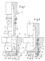
- Fig. 1
- eine halbgeschnittene Seitenansicht einer Steckverbindung mit einem erfindungsgemäßen Aufnahmeteil und einem noch nicht gesteckten Steckerteil,
- Fig. 2
- die Steckverbindung nach
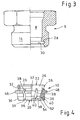
Fig. 1 im gesteckten und verriegelten Zustand des Steckerteils, - Fig. 3
- eine gesonderte Darstellung analog zu
Fig. 1 und 2 nur des Einsatzteils, - Fig. 4
- eine gesonderte Darstellung nur des Halteringelementes,
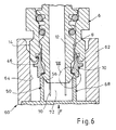
- Fig. 5
- einen Längsschnitt einer speziell an die Erfindung angepaßten Lösevorrichtung mit Darstellung einer gesteckten und verriegelten Steckverbindung nach
Fig. 2 , - Fig. 6
- eine vergrößerte Teilansicht aus
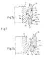
Fig. 5 während des Lösevorgangs und - Fig. 7
- vergrößerte Detailansichten des Bereichs VII in
Fig. 6 , und zwar - Fig. 7a
- in einer Zwischenstellung während des Lösevorgangs und
- Fig. 7b
- die Stellung im gelösten bzw. entriegelten Zustand.
- In den verschiedenen Figuren der Zeichnung sind gleiche Teile stets mit den gleichen Bezugszeichen versehen.
- Eine zunächst in
Fig. 1 und 2 veranschaulichte Steckverbindung besteht aus einem erfindungsgemäßen Aufnahmeteil 2 und einem einzusteckenden Steckerteil 4. Das Aufnahmeteil 2 besteht seinerseits aus einem Einsatzteil 6 mit einer Durchgangsöffnung 8 und einem im Bereich der Durchgangsöffnung 8 gehalterten, zumindest bereichsweise radial elastisch verformbaren Halteringelement 10. Das Steckerteil 4 ist mit einem Steckerschaft 12 umfangsgemäß dichtend in die Durchgangsöffnung 8 des Einsatzteils 6 einsteckbar und in der eingesteckten Position über das Halteringelement 10 gegen Lösen, d. h. gegen Herausziehen, formschlüssig arretierbar bzw, verrastbar. - In der dargestellten Ausführungsform weist das Einsatzteil 6 ein Außengewinde 14 auf, so dass es als Einschraubteil bzw. Überwurfschraube in eine entsprechende Gewindebohrung eines nicht dargestellten, praktisch beliebigen Gehäuseteils, beispielsweise eines Druckaggregates, einschraubbar ist. Alternativ könnte das Einsatzteil 6 aber auch über andere geeignete Verbindungsmittel mit dem Gehäuseteil lösbar verbunden werden, beispielsweise über eine Bajonettverbindung oder dergleichen.
- Erfindungsgemäß ist das Halteringelement 10 auf der der Stecker-Einsteckseite 16 gegenüberliegenden Stirnseite 18 des Einsatzteils 6 mit einem Stecker-Arretierabschnitt 20 außerhalb der Durchgangsöffnung 8, also vor der Stirnseite 18, angeordnet und greift zur Halterung über einen Halteabschnitt 22 rastend in das Einsatzteil 6 ein.
- Gemäß
Fig. 4 ist das Halteringelement 10 mit seinen beiden Abschnitten, dem Arretierabschnitt 20 und dem Halteabschnitt 22, als einstückiges Formteil aus Kunststoff ausgebildet, beispielsweise aus POM oder dergleichen. Dabei ist der Halteabschnitt 22 von einem axial in die Durchgangsöffnung 8 eingreifenden Ringkragen 24 mit einer radial nach außen vorspringenden Rastkante 26 gebildet. Diese Rastkante 26 hintergreift formschlüssig rastend eine innerhalb der Durchgangsöffnung 8 durch eine Ringnut 28 gebildete Haltekante 30 (siehe dazu insbesondereFig. 3 sowieFig. 1 und 2 ). Bei der mit der Haltekante 30 zusammenwirkenden Rastkante 26 kann es sich grundsätzlich um eine umfangsgemäß geschlossene Rastverbindung handeln, wobei die Rastkante 26 als radial federnde Rastnase ausgebildet sein kann. Vorzugsweise ist aber vorgesehen, dass der Ringkragen 24 im Bereich der Rastkante 26 durch mindestens zwei diametral gegenüberliegende axiale Schlitze 32 (sieheFig. 4 ) mindestens in zwei radial federelastische Rastbereiche unterteilt ist. - Gemäß
Fig. 2 wird trotz dieser bevorzugten Radialelastizität eine sichere Halterung des Halteringelementes 10 dadurch erreicht, dass der Halteabschnitt 22 durch den eingesteckten und verrasteten Steckerschaft 12 gegen Lösen von der Haltekante 30 (bzw. aus der Ringnut 28) blockiert wird, und zwar durch radiale Anlage der elastischen Rastbereiche des Halteabschnittes 22 am Außenumfang des Steckerschaftes 12. Diese Halterung ist für den Einsteckvorgang des Steckerschaftes 12 wichtig, um zu vermeiden, dass der Steckerschaft 12 beim Einstecken womöglich das Halteringelement 10 von dem Einsatzteil 6 lösen könnte. Dies ist durch die beschriebene Ausgestaltung ausgeschlossen. - Wie sich weiterhin aus
Fig. 1, 2 und4 ergibt, besteht der Arretierabschnitt 20 des Halteringelementes 10 aus mehreren (mindestens zwei) radialsymmetrisch ausgebildeten, radial federelastischen Rastarmen 36, die jeweils durch axiale Schlitze 38 voneinander getrennt sind. Diese Rastarme 36 weisen radial nach innen weisende Rastansätze 40 auf, die mit einer Raststufe 42 des eingesteckten Steckerschaftes 12 formschlüssig rastend zusammenwirken. Die Raststufe 42 des Steckerschaftes 12 ist in der dargestellten Ausführung von einer äußeren Steckerringnut 44 gebildet (siehe insbesondereFig. 1 ). - Das Halteringelement 10 weist ferner auf seinem Außenumfang einen radialen Ringansatz 46 auf, der zur Einsetzbegrenzung, vor allem aber auch zur Abstützung von in Stecker-Löserichtung (Zugrichtung) wirkenden Haltekräften, vor der Stirnseite 18 des Einsatzteils 6 liegt. Durch diese Abstützung können vorteilhafterweise sehr hohe Haltekräfte aufgenommen werden. Gemäß
Fig. 4 erstrecken sich hierbei die die Rastarme 36 trennenden Schlitze 38 axial über den Ringansatz 46 hinaus, so dass auch der Ringansatz 46 in mehrere Abschnitte unterteilt ist; jeder dieser Abschnitte ist an einem der Rastarme 36 vorhanden. - Wie weiterhin am Besten in
Fig. 4 zu sehen ist, sind einerseits die den Halteabschnitt 22 unterteilenden Schlitze 32 und andererseits die die Rastarme 36 trennenden Schlitze 38 in Umfangsrichtung gegeneinander versetzt, wobei sie sich vorzugsweise in axialer Richtung gesehen überlappen. Dadurch hat das Halteringelement 10 in Umfangsrichtung praktisch eine mäanderförmige Gestalt, wobei einerseits jeweils benachbarte Rastarme 36 über einen der Rastbereiche des Halteabschnittes 22 bzw. andererseits jeweils benachbarte Rastbereiche des Halteabschnittes 22 über einen der Rastarme 36 verbunden sind. Diese Ausgestaltung führt zu einer sehr geringen axialen Baulänge bzw. Bauhöhe des Halteringelementes 10. - In weiterer Ausgestaltung der Erfindung ist das Halteringelement 10 auf seiner freien, die Stirnseite 18 des Einsatzteils 6 überragenden Seite derart ausgebildet, dass es mittels eines Lösewerkzeugs 50 (vgl. dazu
Fig. 5 bis 7 ) zur Freigabe des Steckerteils 4 durch Aufheben der formschlüssigen Verrastung radial spreizbar ist. Dazu weisen die Rastarme 36 an ihren freien Stirnenden axiale, sich über die Rastansätze 40 hinaus erstreckende Löseansätze 52 mit inneren, insgesamt konusförmigen Schrägflächen 54 derart auf, dass mit einem im Wesentlichen hülsenförmigen Lösewerkzeug 50 durch axialen Andruck über die Schrägflächen 54 die Rastarme 36 spreizbar sind, und zwar soweit, bis die Rastansätze 40 in radialer Richtung die Raststufe 42 des Steckerschaftes 12 freigeben (siehe dazuFig. 7b ). Dabei ist es zusätzlich vorteilhaft, dass in der verrasteten Arretierstellung zwischen einer am freien Ende des Steckerschaftes 12 gebildeten äußeren Konusfläche 56 und den Schrägflächen 54 der Rastarme 36 ein sich in Einführrichtung des Lösewerkzeugs 50 verengender Einführringraum 58 ergibt, wozu aufFig. 7a verwiesen wird. Hierdurch ergibt sich die Möglichkeit, das hülsenförmige Lösewerkzeug 50 derart durch Schlitze in einzelne radial verformbare Abschnitte zu unterteilen, das diese über die Konusfläche 56 des Steckerschaftes 12 zusätzlich radial nach außen verformt werden und dadurch das Spreizen der Rastarme 36 noch unterstützt wird. Diese vorteilhafte Ausgestaltung trägt zu einer sehr kleinen und kompakten Bauform der Steckverbindung bzw. des Aufnahmeteils 2 bei, weil ohne die bevorzugte radiale Verformbarkeit des Lösewerkzeugs 50 bzw. der Hülsen-Abschnitte das Halteringelement 10 im Bereich der Schrägflächen 54 mit größeren Durchmesser, d. h. mit radial größeren Schrägflächen 54, ausgebildet sein müßte, um mit dem - dann starren, unbeweglichen - Löseabschnitt 68 übe die Schrägflächen 54 die Rastarme 36 vollständig bis zur Freigabe des Steckerteils 4 spreizen zu können. - Grundsätzlich kann es sich bei dem Lösewerkzeug 50 um ein manuell zuzuführendes Teil handeln. Allerdings betrifft die vorliegende Erfindung auch eine speziell angepaßte Lösevorrichtung 60 (siehe
Fig. 5 und6 ), wobei das Lösewerkzeug 50 innerhalb eines Gehäuses 62 angeordnet ist. Das Gehäuse 62 weist eine Aufnahmeöffnung 64 für das Einsatzteil 6 auf, wobei es sich bei der dargestellten Ausführung entsprechend dem Außengewinde 14 um eine Gewindebohrung handelt. Insofern entspricht die Aufnahmeöffnung 64 derjenigen des jeweiligen Gehäuseteils, für das das Aufnahmeteil 2 vorgesehen ist. Hierbei ist das Lösewerkzeug 50 derart in dem Gehäuse 62 angeordnet, dass durch Einsetzen bzw. Einschrauben des Aufnahmeteils 2 in die Aufnahmeöffnung 64 das Lösewerkzeug 50 selbsttätig gegen die Schrägflächen 54 der Rastarme 36 zum Spreizen derselben wirkt. Dabei ist bevorzugt das Lösewerkzeug 50 derart in Richtung einer Einsetzachse 66 beweglich geführt und mit einer Federkraft F beaufschlagt, dass es stets mit einer vorbestimmten maximalen, der Federkraft F entsprechenden Betätigungskraft gegen das Halteringelement 10 wirkt. Dadurch wird somit eine Kraftbegrenzung erreicht, so dass die Betätigungskraft nicht von dem Maß des Einschraubens abhängt, sondern allein von der Federkraft F. Zudem bewirkt die Axialbeweglichkeit des Lösewerkzeugs 50 in Verbindung mit der Federkraft auch einen Ausgleich von Fertigungstoleranzen. - Wie oben bereits angedeutet wurde, ist das Lösewerkzeug 50 gemäß
Fig. 5 im Bereich eines hülsenförmigen Löseabschnittes 68 durch axiale Schlitze 70 in mehrere radialelastisch verformbare Abschnitte 72 unterteilt. Diese Abschnitte 72 sind gemäßFig. 7 durch Zusammenwirken mit der Konusfläche 56 des Steckerschaftes 12 derart spreizbar, dass dadurch ein zusätzliches Spreizen der Rastarme 36 des Halteringelementes 10 bewirkt wird. Dies ist anhand der inFig. 7a eingezeichneten Pfeile leicht nachvollziehbar; durch Axialbewegung in Pfeilrichtung 74 wirkt der Steckerschaft 12 mit der Konusfläche 56 gegen die Lösewerkzeug-Abschnitte 72, so dass diese in Pfeilrichtung 76 gespreizt werden. Wenn nachfolgend die Abschnitte 72 zur Anlage an den Schrägflächen 54 der Rastarme 36 kommen, wird dadurch eine verstärkte Spreizbewegung in Pfeilrichtung 78 bis in die inFig. 7b dargestellte Lösestellung bewirkt.
Claims (16)
- Aufnahmeteil (2) einer Fluid-Steckverbindung, bestehend aus einem lösbar in eine Anschlußöffnung eines Gehäuseteils einsetzbaren Einsatzteil (6) mit einer Durchgangsöffnung (8) und einem derart im Bereich der Durchgangsöffnung (8) gehalterten, radialelastisch verformbaren Haltering (10), dass ein mit einem Steckerschaft (12) von einer Einsteckseite (16) her dichtend in die Durchgangsöffnung (8) einzusteckendes Steckerteil (4) durch das Halteringelement (10) formschlüssig gegen Lösen verrastbar ist, wobei das Halteringelement (10) auf der der Einsteckseite (16) gegenüberliegenden Stirnseite (18) des Einsatzteils (6) mit einem Stecker-Arretierabschnitt (20) außerhalb der Durchgangsöffnung (8) des Einsatzteils (6) angeordnet ist und über einen in das Einsatzteil (6) eingreifenden Halteabschnitt (22) mit dem Einsatzteil (6) verbunden ist,
dadurch gekennzeichnet, dass das Halteringelement (10) über den Halteabschnitt (22) mit dem Einsatzteil (6) verrastet ist und auf seinem Außenumfang einen radialen Ringansatz (46) aufweist, der zur Aufnahme von in Löserichtung wirkenden Stecker-Haltekräften und zur Einsetzbegrenzung vor der Stirnseite (18) des Einsatzteils (6) liegt. - Aufnahmeteil nach Anspruch 1,
dadurch gekennzeichnet, dass das Halteringelement (10) mit dem Arretierabschnitt (20) und dem Halteabschnitt (22) als einstückiges Formteil aus Kunststoff ausgebildet ist. - Aufnahmeteil nach Anspruch 1 oder 2,
dadurch gekennzeichnet, dass der Halteabschnitt (22) von einem axial in die Durchgangsöffnung (8) eingreifenden Ringkragen (24) mit einer radial nach außen vorspringenden und eine innerhalb der Durchgangsöffnung (8) gebildete Haltekante (30) formschlüssig rastend hintergreifenden Rastkante (26) gebildet ist. - Aufnahmeteil nach Anspruch 3,
dadurch gekennzeichnet, dass der Ringkragen (24) im Bereich der Rastkante (26) durch mindestens zwei axiale Schlitze (32) in radial federelastische Rastbereiche unterteilt ist. - Aufnahmeteil nach Anspruch 3 oder 4,
dadurch gekennzeichnet, dass derHalteabschnitt(22)des Halteringelementes (10) derart in die Durchgangsöffnung (8) des Einsatzteils (6) eingreift, dass er durch den eingesteckten und verrasteten Steckerschaft (12) gegen Lösen von der Haltekante (30) blockiert wird. - Aufnahmeteil nach einem der Ansprüche 1 bis 5,
dadurch gekennzeichnet, dass der Arretierabschnitt (20) aus mindestens zwei radialsymmetrisch ausgebildeten, jeweils durch axiale Schlitze (38) getrennten und radial federelastischen Rastarmen (36) mit radial nach innen weisenden Rastansätzen (40) besteht, die mit einer Raststufe (42) des eingesteckten Steckerschaftes (12) formschlüssig rastend zusammenwirken. - Aufnahmeteil nach Anspruch 6,
dadurch gekennzeichnet, dass sich die die Rastarme (36) voneinander trennenden Schlitze (38) axial über den Bereich des Ringansatzes (46) hinaus erstrecken. - Aufnahmeteil nach Anspruch 4 und Anspruch 6 oder 7,
dadurch gekennzeichnet, dass die den Halteabschnitt (22) unterteilenden Schlitze (32) einerseits und die die Rastarme (36) trennenden Schlitze (38) andererseits in Umfangsrichtung gegeneinander versetzt sind, wobei sie sich vorzugsweise in axialer Richtung überlappen. - Aufnahmeteil nach einem der Ansprüche 1 bis 8,
dadurch gekennzeichnet, dass das Halteringelement (10) auf seiner freien, in die der Einsteckseite (16) gegenüberliegende Richtung weisenden Seite derart ausgebildet ist, dass es mittels eines Lösewerkzeugs (50) zur Freigabe des Steckerteils (4) radial spreizbar ist. - Aufnahmeteil nach einem der Ansprüche 6 bis 9,
dadurch gekennzeichnet, dass dieRastarme(36)anihren freien Stirnenden axiale, sich über die Rastansätze (40) hinaus erstreckende Löseansätze (52) mit inneren, insgesamt konusförmigen Schrägflächen (54) derart aufweisen, dass mit einem im Wesentlichen hülsenförmigen Lösewerkzeug (50) durch axialen Andruck über die Schrägflächen (54) die Rastarme (36) spreizbar sind. - Aufnahmeteil nach Anspruch 10,
dadurch gekennzeichnet, dass derSteckerschaft(12)an seinem freien Ende eine äußere Konusfläche (56) derart aufweist, dass sich in der verrasteten Arretierstellung zwischen der Konusfläche (56) und den Schrägflächen (54) der Rastarme (36) ein sich in Einführrichtung des Lösewerkzeugs (50) verengender Einführringraum (58) ergibt. - Aufnahmeteil nach einem oder mehreren der vorhergehenden Ansprüche mit einer Lösevorrichtung (60) zum Lösen eines eingesteckten und arretierten Steckerteils (4) von dem Aufnahmeteil (2),
gekennzeichnet durch ein im Wesentlichen hülsenförmiges Lösewerkzeug (50) zum Spreizen der Rastarme (36) durch axiales Andrücken gegen das Halteringelement (10). - Aufnahmeteil nach Anspruch 12,
dadurch gekennzeichnet, dass das Lösewerkzeug (50) derart in einem eine Aufnahmeöffnung (64) für das Einsatzteil (6) aufweisenden Gehäuse (62) angeordnet ist, dass durch Einsetzen des Aufnahmeteils (2) in die Aufnahmeöffnung (64) das Lösewerkzeug (50) selbsttätig gegen die Schrägflächen (54) der Rastarme (36) zum Spreizen derselben wirkt. - Aufnahmeteil nach Anspruch 13,
dadurch gekennzeichnet, dass das Lösewerkzeug (50) derart in Richtung einer Einsetzachse (66) beweglich geführt und mit einer Federkraft (F) beaufschlagt ist, dass das Lösewerkzeug (50) mit einer vorbestimmten, der Federkraft (F) entsprechenden Betätigungskraft gegen das Halteringelement (10) wirkt. - Aufnahmeteil nach einem der Ansprüche 12 bis 14,
dadurch gekennzeichnet, dass das Lösewerkzeug (50) im Bereich eines hülsenförmigen Löseabschnittes (68) durch axiale Schlitze (70) in mehrere radialelastisch verformbare Abschnitte (72) unterteilt ist, die durch Zusammenwirken mit einer Konusfläche (56) des Steckerschaftes (12) derart spreizbar sind, dass dadurch ein zusätzliches Spreizen der Rastarme (36) des Halteringelementes (10) bewirkt wird. - Aufnahmeteil nach einem der Ansprüche 13 bis 15,
dadurch gekennzeichnet, dass dieAufnahmeöffnung(64)des Gehäuses (62) als Gewindebohrung zum Einschrauben eines Außengewindes (14) des Einsatzteils (6) ausgebildet ist.
Applications Claiming Priority (3)
| Application Number | Priority Date | Filing Date | Title |
|---|---|---|---|
| DE20215593U DE20215593U1 (de) | 2002-10-10 | 2002-10-10 | Aufnahmeteil einer Fluid-Steckverbindung |
| DE20215593U | 2002-10-10 | ||
| PCT/EP2003/010901 WO2004036103A1 (de) | 2002-10-10 | 2003-10-02 | Aufnahmeteil einer fluid-steckverbindung |
Publications (2)
| Publication Number | Publication Date |
|---|---|
| EP1549873A1 EP1549873A1 (de) | 2005-07-06 |
| EP1549873B1 true EP1549873B1 (de) | 2010-12-15 |
Family
ID=32010555
Family Applications (1)
| Application Number | Title | Priority Date | Filing Date |
|---|---|---|---|
| EP03769345A Expired - Lifetime EP1549873B1 (de) | 2002-10-10 | 2003-10-02 | Aufnahmeteil einer fluid-steckverbindung |
Country Status (5)
| Country | Link |
|---|---|
| EP (1) | EP1549873B1 (de) |
| AT (1) | ATE491907T1 (de) |
| AU (1) | AU2003277924A1 (de) |
| DE (2) | DE20215593U1 (de) |
| WO (1) | WO2004036103A1 (de) |
Cited By (1)
| Publication number | Priority date | Publication date | Assignee | Title |
|---|---|---|---|---|
| WO2022218533A1 (en) * | 2021-04-15 | 2022-10-20 | Oetiker Schweiz Ag | Quick connector made of plastics |
Families Citing this family (5)
| Publication number | Priority date | Publication date | Assignee | Title |
|---|---|---|---|---|
| FR2873186A1 (fr) * | 2004-07-19 | 2006-01-20 | Parker Hannifin France Sas Soc | Raccord pour conduit de fluides hydrauliques ou pneumatiques |
| DE102007001874A1 (de) * | 2007-01-12 | 2008-07-24 | Knorr-Bremse Systeme für Nutzfahrzeuge GmbH | Kombinierter Betriebsbrems- und Federspeicherbremszylinder mit Druckmittelanschlusskupplung |
| JP2015197195A (ja) * | 2014-04-03 | 2015-11-09 | ニッタ株式会社 | 狭所配管用継手 |
| CN110034527B (zh) * | 2019-05-05 | 2024-06-04 | 舟山美通信息技术有限责任公司 | 一种光电通用灌封式水密穿舱件 |
| DE102021102585A1 (de) | 2021-02-04 | 2022-08-04 | Johannes Schäfer vorm. Stettiner Schraubenwerke GmbH & Co. KG | Steckverbindungen zum lösbaren Verbinden von Leitungen und System umfassend eine solche Steckverbindung |
Family Cites Families (5)
| Publication number | Priority date | Publication date | Assignee | Title |
|---|---|---|---|---|
| DE2824943C2 (de) | 1978-06-07 | 1986-07-31 | Armaturenfabrik Hermann Voss GmbH + Co, 5272 Wipperfürth | Anschlußvorrichtung für Bremsleitungen |
| DE8205016U1 (de) * | 1982-02-24 | 1982-09-02 | Johannes Schäfer vorm. Stettinger Schraubenwerke GmbH & Co KG, 6303 Hungen | Kupplung fuer druckleitungen |
| DE3327784A1 (de) * | 1983-08-02 | 1985-02-14 | Armaturenfabrik Hermann Voss GmbH + Co, 5272 Wipperfürth | Verbindungsvorrichtung fuer druckleitungen |
| DE3341030A1 (de) * | 1983-11-12 | 1985-05-23 | Armaturenfabrik Hermann Voss GmbH + Co, 5272 Wipperfürth | Verbindungsvorrichtung fuer druckleitungen mit unverlierbarem haltering |
| DE29913750U1 (de) | 1999-08-06 | 2000-12-14 | Armaturenfabrik Hermann Voss GmbH + Co, 51688 Wipperfürth | Steckverbinder für Druckleitungssysteme |
-
2002
- 2002-10-10 DE DE20215593U patent/DE20215593U1/de not_active Expired - Lifetime
-
2003
- 2003-10-02 DE DE50313331T patent/DE50313331D1/de not_active Expired - Lifetime
- 2003-10-02 WO PCT/EP2003/010901 patent/WO2004036103A1/de not_active Ceased
- 2003-10-02 AU AU2003277924A patent/AU2003277924A1/en not_active Abandoned
- 2003-10-02 EP EP03769345A patent/EP1549873B1/de not_active Expired - Lifetime
- 2003-10-02 AT AT03769345T patent/ATE491907T1/de active
Cited By (2)
| Publication number | Priority date | Publication date | Assignee | Title |
|---|---|---|---|---|
| WO2022218533A1 (en) * | 2021-04-15 | 2022-10-20 | Oetiker Schweiz Ag | Quick connector made of plastics |
| US12276362B2 (en) | 2021-04-15 | 2025-04-15 | Oetiker Schweiz Ag | Quick connector made of plastics |
Also Published As
| Publication number | Publication date |
|---|---|
| AU2003277924A8 (en) | 2004-05-04 |
| EP1549873A1 (de) | 2005-07-06 |
| ATE491907T1 (de) | 2011-01-15 |
| DE50313331D1 (de) | 2011-01-27 |
| DE20215593U1 (de) | 2004-03-11 |
| WO2004036103A1 (de) | 2004-04-29 |
| WO2004036103A8 (de) | 2005-05-26 |
| AU2003277924A1 (en) | 2004-05-04 |
Similar Documents
| Publication | Publication Date | Title |
|---|---|---|
| DE2912160C2 (de) | ||
| EP3173675B1 (de) | Schlauchanschluss | |
| CH648392A5 (de) | Anschlussverbindungsstueck fuer leitungen zum fuehren von gasfoermigen oder fluessigen medien. | |
| EP2542815B1 (de) | Steckverbinder für medienleitungen | |
| DE102017011081A1 (de) | Filtersystem und Filterelement | |
| EP2050996A1 (de) | Steckbarer und verrastbarer Leitungsverbinder | |
| EP1549873B1 (de) | Aufnahmeteil einer fluid-steckverbindung | |
| EP0549860A1 (de) | Vorrichtung zum gegenseitigen Verbinden von zwei Leitungen, insbesondere Kraftstoffleitungen | |
| EP0185802B1 (de) | Verbindungsvorrichtung für Druckleitungen mit unverlierbarem Haltering | |
| DE102007059329A1 (de) | Steckverbindung für Rohrleitungen | |
| EP0733845A1 (de) | Anschlussvorrichtung zum Anschluss von Rohrleitungen an ein Aggregateteil | |
| EP1006307B1 (de) | Steckkupplung | |
| DE4308526B4 (de) | Steckkupplung für Rohr- und/oder Schlauchleitungen | |
| DE102016101533A1 (de) | Kupplungskörper für eine Steckverbindung von Rohrleitungen, insbesondere Kunststoffrohrleitungen | |
| EP0451739A2 (de) | Kupplungsstück | |
| DE19705167C5 (de) | Steckverbindung für Rohrleitungen | |
| DE19745604C1 (de) | Steckanschluß | |
| EP1074782B1 (de) | Steckverbinder für Druckleitungssysteme | |
| DE4104009C2 (de) | Kupplungsstück . | |
| DE102005038439A1 (de) | Steckverbindung für Fluid-Leitungen | |
| DE3341030C2 (de) | ||
| DE102009008609B4 (de) | Steckverbindung für Fluid-Leitungen | |
| DE112004001777B4 (de) | Anschlussvorrichtung für Medienleitungen | |
| DE202007004204U1 (de) | Anschlussvorrichtung für Medienleitungen | |
| EP1233227A1 (de) | Steckverbindung für Strömungsmittelleitungen |
Legal Events
| Date | Code | Title | Description |
|---|---|---|---|
| PUAI | Public reference made under article 153(3) epc to a published international application that has entered the european phase |
Free format text: ORIGINAL CODE: 0009012 |
|
| 17P | Request for examination filed |
Effective date: 20050314 |
|
| AK | Designated contracting states |
Kind code of ref document: A1 Designated state(s): AT BE BG CH CY CZ DE DK EE ES FI FR GB GR HU IE IT LI LU MC NL PT RO SE SI SK TR |
|
| AX | Request for extension of the european patent |
Extension state: AL LT LV MK |
|
| DAX | Request for extension of the european patent (deleted) | ||
| 17Q | First examination report despatched |
Effective date: 20050823 |
|
| GRAP | Despatch of communication of intention to grant a patent |
Free format text: ORIGINAL CODE: EPIDOSNIGR1 |
|
| GRAS | Grant fee paid |
Free format text: ORIGINAL CODE: EPIDOSNIGR3 |
|
| GRAA | (expected) grant |
Free format text: ORIGINAL CODE: 0009210 |
|
| AK | Designated contracting states |
Kind code of ref document: B1 Designated state(s): AT BE BG CH CY CZ DE DK EE ES FI FR GB GR HU IE IT LI LU MC NL PT RO SE SI SK TR |
|
| REG | Reference to a national code |
Ref country code: GB Ref legal event code: FG4D Free format text: NOT ENGLISH Ref country code: CH Ref legal event code: EP |
|
| REG | Reference to a national code |
Ref country code: IE Ref legal event code: FG4D |
|
| REF | Corresponds to: |
Ref document number: 50313331 Country of ref document: DE Date of ref document: 20110127 Kind code of ref document: P |
|
| REG | Reference to a national code |
Ref country code: NL Ref legal event code: T3 |
|
| REG | Reference to a national code |
Ref country code: SE Ref legal event code: TRGR |
|
| PG25 | Lapsed in a contracting state [announced via postgrant information from national office to epo] |
Ref country code: CY Free format text: LAPSE BECAUSE OF FAILURE TO SUBMIT A TRANSLATION OF THE DESCRIPTION OR TO PAY THE FEE WITHIN THE PRESCRIBED TIME-LIMIT Effective date: 20101215 Ref country code: FI Free format text: LAPSE BECAUSE OF FAILURE TO SUBMIT A TRANSLATION OF THE DESCRIPTION OR TO PAY THE FEE WITHIN THE PRESCRIBED TIME-LIMIT Effective date: 20101215 Ref country code: SI Free format text: LAPSE BECAUSE OF FAILURE TO SUBMIT A TRANSLATION OF THE DESCRIPTION OR TO PAY THE FEE WITHIN THE PRESCRIBED TIME-LIMIT Effective date: 20101215 Ref country code: BG Free format text: LAPSE BECAUSE OF FAILURE TO SUBMIT A TRANSLATION OF THE DESCRIPTION OR TO PAY THE FEE WITHIN THE PRESCRIBED TIME-LIMIT Effective date: 20110315 |
|
| REG | Reference to a national code |
Ref country code: IE Ref legal event code: FD4D |
|
| PG25 | Lapsed in a contracting state [announced via postgrant information from national office to epo] |
Ref country code: ES Free format text: LAPSE BECAUSE OF FAILURE TO SUBMIT A TRANSLATION OF THE DESCRIPTION OR TO PAY THE FEE WITHIN THE PRESCRIBED TIME-LIMIT Effective date: 20110326 Ref country code: EE Free format text: LAPSE BECAUSE OF FAILURE TO SUBMIT A TRANSLATION OF THE DESCRIPTION OR TO PAY THE FEE WITHIN THE PRESCRIBED TIME-LIMIT Effective date: 20101215 Ref country code: IE Free format text: LAPSE BECAUSE OF FAILURE TO SUBMIT A TRANSLATION OF THE DESCRIPTION OR TO PAY THE FEE WITHIN THE PRESCRIBED TIME-LIMIT Effective date: 20101215 Ref country code: PT Free format text: LAPSE BECAUSE OF FAILURE TO SUBMIT A TRANSLATION OF THE DESCRIPTION OR TO PAY THE FEE WITHIN THE PRESCRIBED TIME-LIMIT Effective date: 20110415 Ref country code: GR Free format text: LAPSE BECAUSE OF FAILURE TO SUBMIT A TRANSLATION OF THE DESCRIPTION OR TO PAY THE FEE WITHIN THE PRESCRIBED TIME-LIMIT Effective date: 20110316 Ref country code: CZ Free format text: LAPSE BECAUSE OF FAILURE TO SUBMIT A TRANSLATION OF THE DESCRIPTION OR TO PAY THE FEE WITHIN THE PRESCRIBED TIME-LIMIT Effective date: 20101215 |
|
| PG25 | Lapsed in a contracting state [announced via postgrant information from national office to epo] |
Ref country code: RO Free format text: LAPSE BECAUSE OF FAILURE TO SUBMIT A TRANSLATION OF THE DESCRIPTION OR TO PAY THE FEE WITHIN THE PRESCRIBED TIME-LIMIT Effective date: 20101215 Ref country code: SK Free format text: LAPSE BECAUSE OF FAILURE TO SUBMIT A TRANSLATION OF THE DESCRIPTION OR TO PAY THE FEE WITHIN THE PRESCRIBED TIME-LIMIT Effective date: 20101215 |
|
| PLBE | No opposition filed within time limit |
Free format text: ORIGINAL CODE: 0009261 |
|
| STAA | Information on the status of an ep patent application or granted ep patent |
Free format text: STATUS: NO OPPOSITION FILED WITHIN TIME LIMIT |
|
| PG25 | Lapsed in a contracting state [announced via postgrant information from national office to epo] |
Ref country code: DK Free format text: LAPSE BECAUSE OF FAILURE TO SUBMIT A TRANSLATION OF THE DESCRIPTION OR TO PAY THE FEE WITHIN THE PRESCRIBED TIME-LIMIT Effective date: 20101215 |
|
| 26N | No opposition filed |
Effective date: 20110916 |
|
| REG | Reference to a national code |
Ref country code: DE Ref legal event code: R097 Ref document number: 50313331 Country of ref document: DE Effective date: 20110916 |
|
| BERE | Be: lapsed |
Owner name: VOSS AUTOMOTIVE G.M.B.H. Effective date: 20111031 |
|
| PG25 | Lapsed in a contracting state [announced via postgrant information from national office to epo] |
Ref country code: MC Free format text: LAPSE BECAUSE OF NON-PAYMENT OF DUE FEES Effective date: 20111031 |
|
| REG | Reference to a national code |
Ref country code: CH Ref legal event code: PL |
|
| GBPC | Gb: european patent ceased through non-payment of renewal fee |
Effective date: 20111002 |
|
| REG | Reference to a national code |
Ref country code: FR Ref legal event code: ST Effective date: 20120629 |
|
| PG25 | Lapsed in a contracting state [announced via postgrant information from national office to epo] |
Ref country code: LI Free format text: LAPSE BECAUSE OF NON-PAYMENT OF DUE FEES Effective date: 20111031 Ref country code: BE Free format text: LAPSE BECAUSE OF NON-PAYMENT OF DUE FEES Effective date: 20111031 Ref country code: CH Free format text: LAPSE BECAUSE OF NON-PAYMENT OF DUE FEES Effective date: 20111031 |
|
| PG25 | Lapsed in a contracting state [announced via postgrant information from national office to epo] |
Ref country code: FR Free format text: LAPSE BECAUSE OF NON-PAYMENT OF DUE FEES Effective date: 20111102 Ref country code: GB Free format text: LAPSE BECAUSE OF NON-PAYMENT OF DUE FEES Effective date: 20111002 |
|
| REG | Reference to a national code |
Ref country code: AT Ref legal event code: MM01 Ref document number: 491907 Country of ref document: AT Kind code of ref document: T Effective date: 20111002 |
|
| PG25 | Lapsed in a contracting state [announced via postgrant information from national office to epo] |
Ref country code: AT Free format text: LAPSE BECAUSE OF NON-PAYMENT OF DUE FEES Effective date: 20111002 |
|
| PG25 | Lapsed in a contracting state [announced via postgrant information from national office to epo] |
Ref country code: LU Free format text: LAPSE BECAUSE OF NON-PAYMENT OF DUE FEES Effective date: 20111002 |
|
| PG25 | Lapsed in a contracting state [announced via postgrant information from national office to epo] |
Ref country code: TR Free format text: LAPSE BECAUSE OF FAILURE TO SUBMIT A TRANSLATION OF THE DESCRIPTION OR TO PAY THE FEE WITHIN THE PRESCRIBED TIME-LIMIT Effective date: 20101215 |
|
| PG25 | Lapsed in a contracting state [announced via postgrant information from national office to epo] |
Ref country code: HU Free format text: LAPSE BECAUSE OF FAILURE TO SUBMIT A TRANSLATION OF THE DESCRIPTION OR TO PAY THE FEE WITHIN THE PRESCRIBED TIME-LIMIT Effective date: 20101215 |
|
| PGFP | Annual fee paid to national office [announced via postgrant information from national office to epo] |
Ref country code: SE Payment date: 20141028 Year of fee payment: 12 |
|
| PGFP | Annual fee paid to national office [announced via postgrant information from national office to epo] |
Ref country code: NL Payment date: 20141028 Year of fee payment: 12 |
|
| PGFP | Annual fee paid to national office [announced via postgrant information from national office to epo] |
Ref country code: IT Payment date: 20141030 Year of fee payment: 12 |
|
| REG | Reference to a national code |
Ref country code: SE Ref legal event code: EUG |
|
| REG | Reference to a national code |
Ref country code: NL Ref legal event code: MM Effective date: 20151101 |
|
| PG25 | Lapsed in a contracting state [announced via postgrant information from national office to epo] |
Ref country code: IT Free format text: LAPSE BECAUSE OF NON-PAYMENT OF DUE FEES Effective date: 20151002 |
|
| PG25 | Lapsed in a contracting state [announced via postgrant information from national office to epo] |
Ref country code: NL Free format text: LAPSE BECAUSE OF NON-PAYMENT OF DUE FEES Effective date: 20151101 Ref country code: SE Free format text: LAPSE BECAUSE OF NON-PAYMENT OF DUE FEES Effective date: 20151003 |
|
| PGFP | Annual fee paid to national office [announced via postgrant information from national office to epo] |
Ref country code: DE Payment date: 20181031 Year of fee payment: 16 |
|
| REG | Reference to a national code |
Ref country code: DE Ref legal event code: R119 Ref document number: 50313331 Country of ref document: DE |
|
| PG25 | Lapsed in a contracting state [announced via postgrant information from national office to epo] |
Ref country code: DE Free format text: LAPSE BECAUSE OF NON-PAYMENT OF DUE FEES Effective date: 20200501 |