EP2701919B1 - Image forming apparatus, controlling method of image forming apparatus, and program - Google Patents
Image forming apparatus, controlling method of image forming apparatus, and program Download PDFInfo
- Publication number
- EP2701919B1 EP2701919B1 EP12777756.3A EP12777756A EP2701919B1 EP 2701919 B1 EP2701919 B1 EP 2701919B1 EP 12777756 A EP12777756 A EP 12777756A EP 2701919 B1 EP2701919 B1 EP 2701919B1
- Authority
- EP
- European Patent Office
- Prior art keywords
- power
- supply switch
- image forming
- forming apparatus
- power state
- Prior art date
- Legal status (The legal status is an assumption and is not a legal conclusion. Google has not performed a legal analysis and makes no representation as to the accuracy of the status listed.)
- Not-in-force
Links
Images


Classifications
-
- H—ELECTRICITY
- H04—ELECTRIC COMMUNICATION TECHNIQUE
- H04N—PICTORIAL COMMUNICATION, e.g. TELEVISION
- H04N1/00—Scanning, transmission or reproduction of documents or the like, e.g. facsimile transmission; Details thereof
- H04N1/00885—Power supply means, e.g. arrangements for the control of power supply to the apparatus or components thereof
- H04N1/00888—Control thereof
- H04N1/00891—Switching on or off, e.g. for saving power when not in use
-
- G—PHYSICS
- G03—PHOTOGRAPHY; CINEMATOGRAPHY; ANALOGOUS TECHNIQUES USING WAVES OTHER THAN OPTICAL WAVES; ELECTROGRAPHY; HOLOGRAPHY
- G03G—ELECTROGRAPHY; ELECTROPHOTOGRAPHY; MAGNETOGRAPHY
- G03G15/00—Apparatus for electrographic processes using a charge pattern
- G03G15/50—Machine control of apparatus for electrographic processes using a charge pattern, e.g. regulating differents parts of the machine, multimode copiers, microprocessor control
- G03G15/5004—Power supply control, e.g. power-saving mode, automatic power turn-off
Definitions
- the present invention relates to an image forming apparatus, a controlling method of the image forming apparatus, and a program for performing the controlling method of the image forming apparatus.
- an image forming apparatus such as a copying machine, a printer or the like which has, in order to achieve power saving of the apparatus as a whole, an automatic off driving circuit for automatically turning off a power-supply switch when the apparatus is not operated or handled for a given time.
- the power-supply switch provided in the image forming apparatus like this has a mechanical relay.
- the mechanical relay is driven by outside signal controlling in a state that the power-supply switch is on, it is possible to perform automatic off driving for turning off the power-supply switch.
- the image forming apparatus which has the above automatic off driving circuit, in order to suppress power consumption of the apparatus, it is desirable to frequently turn off the power-supply switch by performing the automatic off driving when the image forming apparatus is not used.
- the mechanical relay since the mechanical relay has a lifetime, the number of times of controlling the mechanical relay is naturally limited due to its lifetime. More specifically, the lifetime has been defined for each component as the number of times of off/on of the power-supply switch.
- JP 2009-130824 A proposes a method which is used to, in an image forming apparatus of performing automatic off controlling for a power supply by using an element such as a mechanical relay or the like of which the number of times of controlling has been limited as a lifetime, stop performing the automatic off controlling when the number of times of using of the element exceeds a predetermined threshold, for the purpose of preventing deterioration of the element.
- the number of times of off/on of the power-supply switch is different according to a usage environment of a user who uses the image forming apparatus. That is, the number of times of off/on of the power-supply switch is relatively large with respect to the user who uses the image forming apparatus frequently. On the other hand, the number of times of off/on of the power-supply switch is relatively small with respect to the user who does not use the image forming apparatus so much.
- the power-supply switch by which the number of times of off/on is ensured according to the user who uses the image forming apparatus frequently is used, costs of the power-supply switch itself increase. Moreover, in this case, the size of the power-supply switch increases, whereby such an increase of the size of the power-supply switch affects the overall constitution of the image forming apparatus itself.
- US 2011/083027 A1 shows a controller as a controlling unit for an image forming apparatus, providing a normal mode, a first power saving mode, in which the power consumption is smaller than that in the normal mode, a second power saving mode, in which the power consumption is smaller than that in the first power saving mode, and a third power saving mode, in which the power consumption is smaller than that in the second power saving mode.
- a controller for an image forming apparatus which provides a plurality of power saving modes (i.e. the first power saving mode, the second power saving mode and the third power saving mode), which differ in their power consumption.
- JP 2011/039956 A shows another controller as a controlling unit for an image forming apparatus according to the prior art.
- the object of the present invention is achieved by an image forming apparatus having the features of claim 1 and by a controlling method for an image forming apparatus having the features of claim 8.
- FIG. 1 is a block diagram illustrating an example of a constitution of an image forming apparatus according to the first embodiment of the present invention. More specifically, FIG. 1 shows an image forming apparatus 1 according to the present embodiment.
- the image forming apparatus 1 includes a printing unit 12, a reading unit 11, an operation panel 14, a power-supply unit 13, and a controlling unit 10 which controls these units.
- the controlling unit 10 performs various kinds of image processes on the basis of image data received from the reading unit 11, a host computer serving as an external apparatus, a facsimile apparatus connected via a PSTN (public switched telephone network) line (public line), or the like. Then, the controlling unit controls, e.g., the printing unit 12 to form an image on a paper on the basis of the processed image data.
- PSTN public switched telephone network
- the reading unit 11 reads an original copy as the image data, and then transfers the read image to the controlling unit 10.
- the reading unit 11 is equipped with a not-illustrated scanner unit having a function for reading the original copy, and a not-illustrated original copy feeding unit having a function for transporting the original copies.
- the printing unit 12 transports a recording paper, prints as a visible image the image data received from the controlling unit 10 on the transported recording paper in an electrophotographic method or the like, and then discharges the recording paper on which the visible image has been formed outside the image forming apparatus.
- the printing unit 12 includes a not-illustrated paper feeding unit having several kinds of recording paper cassettes, a not-illustrated marking unit having a function for transferring the image data onto the recording paper and fixing the transferred image data to the recording paper, and a not-illustrated paper discharging unit having a function for performing as necessary a sorting process, a stapling process and the like to the recording papers on which the image data have been printed respectively, and outputting the processed recording papers outside the image forming apparatus.
- the operation panel 14 is used to accept, from an operator (user), various kinds of settings and operations for causing the printing unit 12 to perform image forming based on the original copy read by the reading unit 11.
- the operation panel 14 is used to input, via a touch panel thereof, selections of the number of copies of the recording papers to which the image forming should be performed, information concerning image densities in the image forming, and reading resolution (e.g., 300dpi or 600dpi) of the scanner unit used for reading the original copy.
- the power-supply unit 13 is a power-supply circuit which uses an alternate-current commercial power supply (called an AC power supply) as an input. In any case, the power-supply unit 13 generates a voltage 15 for applying a direct-current voltage and/or an alternate-current voltage to the controlling unit 10, the reading unit 11, the printing unit 12 and the operation panel 14. Further, the power-supply unit 13 changes the voltage 15 according to a control signal 16 transferred from the controlling unit 10.
- an AC power supply alternate-current commercial power supply
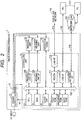
- FIG. 2 is a block diagram illustrating a constitution of the controlling unit 10. Incidentally, it should be noted that, in FIG. 2 , the same elements as those illustrated in FIG. 1 are respectively indicated by the same reference numerals as those illustrated in FIG. 1 .
- the controlling unit 10 includes a plurality of blocks such as a CPU 102, a RAM (random access memory) 103, a ROM (read only memory) 104, a printing unit I/F (interface) 106, a reading unit I/F 108, a modem 111, a line I/F 112, a USB (universal serial bus) I/F 115, a network I/F 118 and the like, and these blocks are mutually connected to others via a system bus 105.
- blocks such as a CPU 102, a RAM (random access memory) 103, a ROM (read only memory) 104, a printing unit I/F (interface) 106, a reading unit I/F 108, a modem 111, a line I/F 112, a USB (universal serial bus) I/F 115, a network I/F 118 and the like, and these blocks are mutually connected to others via a system bus 105.
- a system bus 105 such as
- the CPU 102 totally controls the above blocks respectively according to various kinds of control programs.
- these control programs have been recorded in the program area (program ROM) of the ROM 104 in a computer-readable manner, and these programs are read and executed by the CPU 102.
- various kinds of control programs have been recorded as compressed data in the program area of the ROM 104, these programs are read, extracted and expanded in the RAM 103, and then the extracted and expanded programs are executed by the CPU 102.
- various kinds of control programs as described above may be stored in another not-illustrated storage device such as an HDD (hard disk drive), an SSD (solid state drive) or the like in a compressed state or an uncompressed state.
- the network I/F 118 performs a communication process with a host computer (called a PC (personal computer) hereinafter) 117 via a network (LAN (local area network)) 120 or the like.
- a host computer called a PC (personal computer) hereinafter
- LAN local area network
- the network I/F 118 and the network 120 are mutually connected to each other via a communication cable such as a LAN cable 119 or the like.
- the modem 111 which is connected to a public network line 114 via the line I/F 112, performs a communication process with another image forming apparatus, a facsimile apparatus, a telephone set or the like, which is not illustrated in the drawing.
- the line I/F 112 and the public network line 114 are mutually connected to each other via a telephone line 113 or the like.
- the USB I/F 115 and the PC 117 are mutually connected to each other via a USB code 116 or the like.
- the printing unit I/F 106 serves as an interface for outputting an image signal to the printing unit (printer engine) 12. Further, the reading unit I/F 108 serves as an interface for inputting a read image signal from the reading unit (scanner engine) 11. Furthermore, the CPU 102 is used to process the image signal input from the reading unit I/F 108, and output the processed image signal as a recording image signal to the printing unit I/F 106.
- the CPU 102 is used to display characters and symbols on the display section of the operation panel 14 by using font information stored in the font area (font ROM) of the ROM 104, and to receive instruction information based on a user's instruction from the operation panel 14.
- font information stored in the font area (font ROM) of the ROM 104
- the data area (data ROM) of the ROM 104 has been constituted in a rewritable manner (for example, a flash ROM or the like). Therefore, device information of the image forming apparatus 1, telephone book information of users, department management information and the like have been stored in the data area of the ROM 104 by the CPU 102. Then, the stored information is read and updated as necessary by the CPU 102.
- a clock unit 125 which is backed up by a primary battery, counts date and time on the basis of calendar information previously set by the user of the image forming apparatus 1. Then, the information indicating the date and time counted by the clock unit 125 is read by the CPU 102, and then stored in the predetermined areas in the data areas of the RAM 103 and the ROM 104.
- the power-supply unit 13 changes the voltage 15 of the power-supply unit to be applied to each block in response to the control signal 16 connected to the output port of the CPU 102.
- FIG. 3 is a block diagram illustrating an example of a constitution of the power-supply unit 13 and an example of a constitution of the control signal 16 of the CPU 102 provided in the controlling unit 10.
- the same elements as those illustrated in FIGS. 1 and 2 are respectively indicated by the same reference numerals as those illustrated in FIGS. 1 and 2 .
- the power-supply unit 13 includes a DC power-supply generating unit 131, a transistor unit 132 and a power-supply switch 133.
- the DC power-supply generating unit 131 rectifies and transforms power supplied from a commercial power supply (AC 100V), and then applies the obtained power to the respective blocks of the image forming apparatus 1 as DC power-supply voltages 15a, 15b, 15c and 15d.
- a commercial power supply AC 100V
- the transistor unit 132 is constituted by an FET (field-effect transistor) and the like.
- the transistor unit 132 controls on/off of the DC power-supply voltages 15b, 15c and 15d to be applied respectively to the printing unit 12, the reading unit 11 and the operation panel 14, in response to respective controls signals 16b, 16c and 16d supplied from the CPU 102.
- the signal lines to be used to supply the control signals 16b, 16c and 16d are connected respectively to output ports P2, P3 and P4 of the CPU 102.
- a solenoid 134 is provided in the power-supply switch 133.
- the contact points of switches 135 and 136 are released, whereby the power-supply switch 133 is turned off.
- the controlling unit 10 when the power-supply switch 133 is turned on by a manual operation of the user and thus the power is supplied by the DC power-supply voltage 15a from the DC power-supply generating unit 131, the controlling unit 10 can be operated.
- the power-supply switch 133 has a mechanical relay which includes therein the solenoid 134 and the switches 135 and 136.
- the signal line for supplying the control signal 16a to the power-supply switch 133 is connected to an output port P1 of the CPU 102 via a transistor 130.
- the transistor 130 when a high-level signal is output from the output port P1 of the CPU 102, the transistor 130 is turned on to apply the current to the solenoid 134. That is, at this time, the current flows in the circuit which is constituted by the DC power-supply generating unit 131 ⁇ the solenoid 134 ⁇ the transistor 130 ⁇ a ground GND, thereby driving the solenoid 134.
- the switches 135 and 136 are driven and thus turned off.
- the power-supply switch 133 is turned off by the internal mechanical relay (the solenoid 134 and the switches 135 and 136) driven by the user's manual operation or the control of the CPU 102, whereby the power supply to the image forming apparatus 1 is cut off.
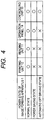
- FIG. 4 is a diagram illustrating power states of the image forming apparatus 1.
- symbols (o, ⁇ ) respectively indicate the power states of the respective blocks. That is, the state that the DC power-supply voltages 15a, 15b, 15c and 15d are applied from the DC power-supply generating unit 131 to the respective blocks is indicated by the symbol "o", while the state that these voltages are not applied is indicated by the symbol " ⁇ ".
- the power-supply voltages are applied to the respective blocks under the control of the above output ports P1 to P4 of the CPU 102.
- a normal state is equivalent to the power state to which the image forming apparatus 1 is transitioned after the power-supply switch 133 was turned on.
- the power-supply voltages are applied from the DC power-supply generating unit 131 to the printing unit 12, the reading unit 11 and the operation panel 14, in addition to the controlling unit 10.
- all the operations of the image forming apparatus 1 can be performed by the user.
- a power saving state is equivalent to the power state to which the image forming apparatus is transitioned in a case where a state that any operation is not performed by the user continues for a predetermined power saving state transition time (Tsl) or more in the normal state.
- the power saving state transition time (Tsl) is previously set in response to an instruction by a user's operation to a not-illustrated key on the operation panel 14, and the set power saving state transition time (Tsl) can be stored in the data area of the ROM 104 and read by the CPU 102.
- the power-supply voltages are applied from the DC power-supply generating unit 131 to the controlling unit 10 and the operation panel 14.
- the power-supply voltages 15b and 15c are not applied respectively to the printing unit 12 and the reading unit 11 by switching the respective control signals 16b and 16c from the output ports P2 and P3 of the controlling unit 10 under the control of the transistor unit 132.
- the power saving state for example, when any one of the following operations (1) to (4) is performed by the user, the performed operation is recognized by the CPU 102, and the control signals 16b and 16c from the respective output ports P2 and P3 are switched so as to apply the power-supply voltages 15b and 15c, whereby the image forming apparatus is returned to the normal state.
- An automatic off driving state is equivalent to the power state to which the image forming apparatus is transitioned in a case where a state that any operation is not performed by the user continues for a predetermined automatic off driving state transition time (Tsh) in the power saving state.
- the automatic off driving state transition time (Tsh) is previously set in response to an instruction by a user's operation to a not-illustrated key on the operation panel 14, and the set automatic off driving state transition time (Tsh) can be stored in the data area of the ROM 104 and read by the CPU 102.
- the automatic off driving state is the power state that automatic off controlling of the power-supply switch 133 is performed from the controlling unit 10.
- the power-supply voltage is applied from the DC power-supply generating unit 131 to the controlling unit 10.
- the power-supply voltages 15b, 15c and 15d are not applied respectively to the printing unit 12, the reading unit 11 and the operation panel 14 by switching the respective control signals 16b, 16c and 16d from the output ports P2, P3 and P4 of the controlling unit 10 under the control of the transistor unit 132.
- the automatic off driving state is the power state capable of minimizing the power consumption and thus minimizing the resistance load of the power-supply switch 133.
- the automatic off driving to the power-supply switch 133 from the controlling unit 10 is performed by supplying the power to the solenoid 134 and thus turning off the switches 135 and 136 under the control of the above output port P1 of the CPU 102.
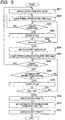
- FIG. 5 is the flow chart indicating an example of the power controlling operation according to the first embodiment of the present invention.
- the respective steps shown in FIG. 5 are carried out by the CPU 102 on the basis of the program stored in the program area of the ROM 104 (or extracted and expanded from the program area of the ROM 104 to the RAM 103).
- a step S501 it is controlled by the CPU 102 to apply the DC power-supply voltages 15b, 15c and 15d from the DC power-supply generating unit 131 by respectively switching the output ports P2, P3 and P4, so as to transition the image forming apparatus to the normal state.
- a numerical value of a normal state elapse time (Tpnr) stored in the data area of the ROM 104 is initialized (cleared) to "0" by the CPU 102.
- a step S503 it is discriminated by the CPU 102 whether or not a user's operation is performed, based on presence/absence of an input signal from the operation panel 14, the network I/F 118, the USB I/F 115 or the modem 111 (S503).
- step S504 the numerical value of the normal state elapse time (Tpnr) stored in the data area of the ROM 104 is updated (counted up) by the CPU 102.
- a step S505 the numerical value of the power saving state transition time (Tsl) previously stored in the data area of the ROM 104 and the numerical value of the normal state elapse time (Tpnr) are compared with each other by the CPU 102, whereby it is discriminated whether or not the numerical value of the normal state elapse time (Tpnr) is larger than the numerical value of the power saving state transition time (Tsl).
- step S506 it is controlled by the CPU 102 not to apply the DC power-supply voltages 15b and 15c from the DC power-supply generating unit 131 by respectively switching the output ports P2 and P3, so as to transition the image forming apparatus 1 to the power saving state.
- a numerical value of a power saving state elapse time (Tpsl) stored in the data area of the ROM 104 is initialized (cleared) to "0" by the CPU 102, and the process is advanced to a step S508.
- step S508 it is discriminated by the CPU 102 whether or not a user's operation is performed, based on presence/absence of an input signal from the operation panel 14, the network I/F 118, the USB I/F 115 or the modem 111.
- a step S511 the numerical value of the automatic off driving state transition time (Tsh) previously stored in the data area of the ROM 104 and the numerical value of the power saving state elapse time (Tpsl) are compared with each other by the CPU 102, whereby it is discriminated whether or not the numerical value of the power saving state elapse time (Tpsl) is larger than the numerical value of the automatic off driving state transition time (Tsh).
- step S512 it is controlled by the CPU 102 not to apply the DC power-supply voltage 15d from the DC power-supply generating unit 131 by switching the output port P4, so as to transition the image forming apparatus 1 to the automatic off driving state.
- step S514 it is controlled by the CPU 102 to switch the output port P1 to "high" to supply the power to the solenoid 134, thereby turning off the power-supply switch 133.
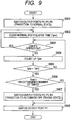
- FIG. 6 is the flow chart indicating an example of the power-supply switch lifetime detection controlling according to the first embodiment of the present invention.
- the respective steps shown in FIG. 6 are carried out by the CPU 102 on the basis of the program stored in the program area of the ROM 104 (or extracted and expanded from the program area of the ROM 104 to the RAM 103).
- the number of off/on per day is limited to about 15 times.
- the upper limit of the number of counting times of off/on of the power-supply switch 133 per day is set to 10 times. Then, when the number of times of off/on exceeds the set 10 times, it is controlled to stop performing the automatic off driving, thereby preventing that the number of times of off/on increases.
- an initial setting (power-supply on initial setting) is performed to the controlling unit 10 of the image forming apparatus 1 by the CPU 102.
- step S602 date and time information (Tpon), which was stored in the data area of the ROM 104 at the time when the power-supply switch 133 was previously turned on by the user, is read and then written in the RAM 103 by the CPU 102.
- Tpon date and time information
- a step S603 current calendar information (e.g., December 3, 2010 - 16:48:53) is read from the clock unit 125 by the CPU 102. Then, the read calendar information is written in the RAM 103 as date and time information (Tponn) indicating the time at which the power-supply switch 133 is turned on this time.
- Tponn date and time information
- Nsw off/on
- the date and time information (Tpon) indicating the date and time at which the power-supply switch 133 was previously turned on is changed (updated) by the date and time information (Tponn) indicating the date and time at which the power-supply switch 133 is turned on this time.
- the obtained date and time information (Tpon) is stored in the data area of the ROM 104 by the CPU 102.
- the read information is the date and time information (Tponn) indicating the date and time at which the power-supply switch 133 is turned on this time.
- the automatic off driving state transition flag (Fsh) is read from the data area of the ROM 104 by the CPU 102.
- the automatic off driving state transition flag (Fsh) is the flag for confirming the transition to the automatic off driving state, which was stored in the data area of the ROM 104 by the CPU 102 at the time of the previous transition to the automatic off driving state. Therefore, on the basis of whether the set value of the automatic off driving state transition flag (Fsh) is "1" or "0", it is possible for the CPU 102 to discriminate whether the previous off of the power-supply switch 133 is based on the automatic off controlling or the user's manual operation.
- step S611 the numerical value of the number of times of off/on (Nsw) of the power-supply switch per day read from the data area of the ROM 104 is updated by performing increment of "1" count by the CPU 102, and the updated number of times of off/on (Nsw) of the power-supply switch per day is stored in the data area of the ROM 104 (update of Nsw by count). Then, the process is advanced to a step S612.
- the process is advanced to a step S610 by the CPU 102.
- the numerical value of the number of times of off/on (Nsw) of the power-supply switch per day read from the data area of the ROM 104 is updated by performing increment of a "small" count by the CPU 102, and the updated number of times of off/on (Nsw) of the power-supply switch per day is stored in the data area of the ROM 104 (update of Nsw by small count). Then, the process is advanced to the step S612.
- the increment of the value (Nsw) by small count indicates the update of the count time based on the lifetime of the power-supply switch 133 previously calculated according to the resistance load of the power-supply switch 133 in the automatic off controlling.
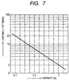
- the lifetime of the power-supply switch 133 to be used will be described with reference to FIG. 7 .
- FIG. 7 is the graph indicating an example of the lifetime curve of the power-supply switch 133.
- a current of the resistance load is plotted along the horizontal axis, and the number of times of off/on being the lifetime of the power-supply switch 133 is plotted along the vertical axis.
- the numerical value of the number of times of off/on (Nsw) of the power-supply switch per day is incremented by "1/10" count (adding 0.1 to the numerical value of Nsw) by the CPU 102.
- the numerical value of the number of times of off/on (Nsw) of the power-supply switch per day may be incremented by "1" count by the CPU 102.
- the CPU 102 can appropriately count the number of times of off/on of the power-supply switch 133, according to whether the previous off of the power-supply switch 133 was based on the automatic off controlling or based on the user's manual operation.
- the numerical value of the number of times of off/on (Nsw) of the power-supply switch per day and a predetermined number of times are compared with each other by the CPU 102.
- the number of times of off/on of the power-supply switch 133 previously stored in the ROM 104 for example, when the number of times of off/on defined as the lifetime of the power-supply switch 133 is equivalent to 20,000 times, it is assumed that the numerical value of "10 times" has been previously stored in the ROM 104 as the number of times of off/on per day. That is, the above predetermined number of times is equivalent to the number of times based on the number of times of off/on defined as the lifetime of the power-supply switch 133.
- the process is advanced to a step S613 by the CPU 102.
- the automatic off driving stop flag (Fst) is not set (Fst stored in the ROM 104 remains "0") by the CPU 102, and the process is advanced to the step S614.
- step S614 the power controlling operation indicated by the flow chart of FIG. 5 is performed by the CPU 102.
- the automatic off driving stop flag (Fst) is the recognition flag for causing the CPU 102 not to transition the image forming apparatus to the automatic off driving state.
- the setting of the automatic off driving state transition flag (Fsh) is discriminated in the step S513 of FIG. 5 , whereby it is controlled to select whether to perform the automatic off driving or maintain the power saving state without performing the automatic off driving until the date and time information (Tpon) is updated. That is, when the counted numerical value of the number of times of off/on (Nsw) of the power-supply switch per day exceeds the first number of times, it is controlled by the CPU 102 not to perform the controlling (automatic off driving) for turning off the power-supply switch.
- this controlling it is possible for the CPU 102 to reduce the number of times of off/on of the power-supply switch 133 by the automatic off driving, thereby enabling to suppress that the power-supply switch 133 comes to its lifetime.
- the image forming apparatus 1 has the two power states of the normal state and the power saving state in addition to the automatic off driving state.
- the power states of the image forming apparatus only have to be two or more.
- the present invention is not limited by the number of power states.
- the constitution of the image forming apparatus 1 such as an increase of the kinds of power supplies from the power-supply unit 13, or an increase of the power supply destinations of the image forming apparatus 1.
- the automatic off driving state only has to be the state capable of performing the driving controlling to the solenoid 134 of the power-supply switch 133, and, to be, among the power states achievable in the image forming apparatus 1, the state capable of minimizing the power.
- the power supply from the DC power-supply generating unit 131 to the solenoid 134 and the output port controlling by the CPU 102 correspond to the automatic off controlling state.
- the number of times of off/on of the power-supply switch 133 to be compared in the process indicated by the flow chart of FIG. 6 is the number of times in the period of one day.
- the relevant period only has to be a specific period by which it is possible to suppress that the power-supply switch 133 comes to its lifetime (for example, one year, one month, one week, a specific time, or the like). That is, it is discriminated by the CPU 102 whether or not the specific period has elapsed, and the number of times of switching is initialized for each specific period (S604 to S605 in FIG. 6 ).
- the resistance load of the power-supply switch is decreased at the time of performing the automatic off driving of the power-supply switch.
- the number of times of off/on of the power-supply switch to be performed in the specific period based on the lifetime of the used power-supply switch is defined.
- the number of times of off/on of the power-supply switch is counted in the specific period.
- the automatic off driving is stopped when the counted number of times of off/on of the power-supply switch reaches the defined number of times.
- the present invention it is possible to extend the lifetime of the power-supply switch while using the conventional power-supply switch as the switch itself. Consequently, it is unnecessary to use the power-supply switch for which the number of times of off/on has been ensured according to the user who uses the image forming apparatus frequently. Thus, it is possible to prevent that the costs of the power-supply switch itself increase, and it is also possible to prevent that the increased size of the power-supply switch affects the overall constitution of the image forming apparatus itself.
- the present invention when the number of times of off/on of the power-supply switch exceeds the predetermined number of times in the predetermined period, it is controlled not to perform the automatic off driving.
- the present invention is not limited to the constitution of controlling not to perform the automatic off driving when the number of times of off/on of the power-supply switch exceeds the predetermined number of times in the predetermined period. That is, the present invention also includes a constitution that the CPU 102 does not perform the controlling based on the number of times of off/on but performs, when performing the automatic off driving, the automatic off driving by transitioning to the power state (automatic off driving state) of which the power consumption is small.
- the power state is transitioned in the order of the normal state ⁇ the power saving state ⁇ the automatic off driving state according to the power controlling indicated by the flow chart of FIG. 5 , and then the automatic off driving of the power-supply switch 133 is performed.
- the automatic off driving of the power-supply switch 133 is performed while the normal state is being maintained, whereby it is possible to turn off the power-supply switch 133 as compared with the first embodiment.
- the second embodiment in the process indicated by the flow chart of FIG. 6 , when the number of times of off/on (Nsw) of the power-supply switch is counted when the power supply is on, the changed counting method in the automatic off driving to be performed in the steps S609 and S610 is not performed. Namely, the number of times of off/on (Nsw) of the power-supply switch is counted as the power-supply off in the normal state in the step S611.
- FIG. 8 is the flow chart indicating an example of the power-supply switch lifetime detection controlling according to the second embodiment of the present invention.
- the respective steps shown in FIG. 8 are carried out by the CPU 102 on the basis of the program stored in the program area of the ROM 104 (or extracted and expanded from the program area of the ROM 104 to the RAM 103).
- steps S801 to S807 are respectively the same as those in the steps S601 to S607 indicated by the flow chart of FIG. 6 , the explanations thereof will be omitted.
- a step S808 the numerical value of the number of times of off/on (Nsw) of the power-supply switch per day read from the data area of the ROM 104 is updated by performing increment of "1" count by the CPU 102 (update of Nsw by count), and the updated number of times of off/on (Nsw) of the power-supply switch per day is stored in the data area of the ROM 104. Then, the process is advanced to a step S809.
- step S809 a power controlling operation illustrated in later-described FIG. 9 is performed.
- FIG. 9 is the flow chart indicating an example of the power controlling operation according to the second embodiment of the present invention.
- the respective steps shown in FIG. 9 are carried out by the CPU 102 on the basis of the program stored in the program area of the ROM 104 (or extracted and expanded from the program area of the ROM 104 to the RAM 103).
- steps S901 to S904 are respectively the same as those in the steps S501 to S504 indicated by the flow chart of FIG. 5 , the explanations thereof will be omitted.
- a step S905 the numerical value of the automatic off driving state transition time (Tsh) previously stored in the data area of the ROM 104 and the numerical value of the normal state elapse time (Tpnr) are compared with each other by the CPU 102, whereby it is discriminated whether or not the numerical value of the normal state elapse time (Tpnr) is larger than the numerical value of the automatic off driving state transition time (Tsh).
- step S906 the numerical value of the number of times of off/on (Nsw) of the power-supply switch per day and the number of times of off/on of the power-supply switch 133 previously stored as a predetermined numerical value in the ROM 104 (a predetermined number of times) are compared with each other by the CPU 102.
- the process is advanced to a step S908 by the CPU 102.
- this step it is controlled to perform the automatic off driving of the power-supply switch 133 while maintaining the normal state. That is, it is controlled by the CPU 102 to switch the output port P1 to "high" while maintaining the normal state to supply the power to the solenoid 134, thereby turning off the power-supply switch 133.
- the process is advanced to a step S907 by the CPU 102.
- it is controlled to transition the image forming apparatus 1 to the automatic off driving state by respectively switching the output ports P2, P3 and P4.
- the step S908 it is controlled by the CPU 102 to perform the automatic off driving of the power-supply switch 133.
- the image forming apparatus After the image forming apparatus was transitioned to the automatic off driving state, it is controlled by the CPU 102 to switch the output port P1 to "high" to supply the power to the solenoid 134, thereby turning off the power-supply switch 133.
- the automatic off driving of the power-supply switch is performed in the normal state maintained. Then, when the number of times of off/on of the power-supply switch has gotten close to the number of times affecting the lifetime of the power-supply switch, it is controlled to perform the automatic off driving after transitioning the power state to the automatic off driving state of reducing the resistance load of the power-supply switch.
- the present embodiment it is possible to extend the lifetime of the power-supply switch while using the conventional power-supply switch as the switch itself. Consequently, it is unnecessary to use the power-supply switch for which the number of times of off/on has been ensured according to the user who uses the image forming apparatus frequently. Thus, it is possible to prevent that the costs of the power-supply switch itself increase, and it is also possible to prevent that the increased size of the power-supply switch affects the overall constitution of the image forming apparatus itself.
- the present invention is also applicable to any electronic device if it can operate in a plurality of power states.
- the structures and the contents of the above various kinds of data are not limited to those described above. Namely, it is needless to say that the above various kinds of data can include various kinds of structures and contents according to their intended purposes and objects.
- the present invention can adopt an embodiment which is recognized as, e.g., a system, an apparatus, a method, a program, or a recording medium. More specifically, the present invention may be applied to a system which is composed of a plurality of devices or to an apparatus which includes only one device.
- the constitution obtained by properly combining the above embodiments is also included in the present invention.
- the present invention is realized by performing the following process in which software (program) for achieving the functions of the above embodiments is supplied to a system or an apparatus via a network or various kinds of storage media and the supplied software is read and actually executed by a computer (or a CPU or an MPU) of the system or the apparatus.
- software program for achieving the functions of the above embodiments is supplied to a system or an apparatus via a network or various kinds of storage media and the supplied software is read and actually executed by a computer (or a CPU or an MPU) of the system or the apparatus.
- the present invention may be applied to a system composed of a plurality of devices or an apparatus having a single device.
- aspects of the present invention can also be realized by a computer of a system or apparatus (or devices such as a CPU or an MPU) that reads out and executes a program recorded on a memory device to perform the functions of the above embodiments, and by a method, the steps of which are performed by a computer of a system or an apparatus by, for example, reading out and executing a program recorded on a memory device to perform the functions of the above embodiments.
- the program is provided to the computer for example via a network or from a recording medium of various types serving as the memory device (e.g., computer-readable medium).
Landscapes
- Engineering & Computer Science (AREA)
- Microelectronics & Electronic Packaging (AREA)
- Physics & Mathematics (AREA)
- General Physics & Mathematics (AREA)
- Multimedia (AREA)
- Signal Processing (AREA)
- Control Or Security For Electrophotography (AREA)
- Accessory Devices And Overall Control Thereof (AREA)
- Power Sources (AREA)
Applications Claiming Priority (2)
| Application Number | Priority Date | Filing Date | Title |
|---|---|---|---|
| JP2011097258A JP5839828B2 (ja) | 2011-04-25 | 2011-04-25 | 画像形成装置、画像形成装置の制御方法、及びプログラム |
| PCT/JP2012/061164 WO2012147827A1 (en) | 2011-04-25 | 2012-04-19 | Image forming apparatus, controlling method of image forming apparatus, and program |
Publications (3)
| Publication Number | Publication Date |
|---|---|
| EP2701919A1 EP2701919A1 (en) | 2014-03-05 |
| EP2701919A4 EP2701919A4 (en) | 2014-09-17 |
| EP2701919B1 true EP2701919B1 (en) | 2020-07-01 |
Family
ID=47072342
Family Applications (1)
| Application Number | Title | Priority Date | Filing Date |
|---|---|---|---|
| EP12777756.3A Not-in-force EP2701919B1 (en) | 2011-04-25 | 2012-04-19 | Image forming apparatus, controlling method of image forming apparatus, and program |
Country Status (5)
| Country | Link |
|---|---|
| US (1) | US20130215449A1 (enExample) |
| EP (1) | EP2701919B1 (enExample) |
| JP (1) | JP5839828B2 (enExample) |
| CN (1) | CN103492188B (enExample) |
| WO (1) | WO2012147827A1 (enExample) |
Families Citing this family (362)
| Publication number | Priority date | Publication date | Assignee | Title |
|---|---|---|---|---|
| US9060770B2 (en) | 2003-05-20 | 2015-06-23 | Ethicon Endo-Surgery, Inc. | Robotically-driven surgical instrument with E-beam driver |
| US20070084897A1 (en) | 2003-05-20 | 2007-04-19 | Shelton Frederick E Iv | Articulating surgical stapling instrument incorporating a two-piece e-beam firing mechanism |
| US11890012B2 (en) | 2004-07-28 | 2024-02-06 | Cilag Gmbh International | Staple cartridge comprising cartridge body and attached support |
| US9072535B2 (en) | 2011-05-27 | 2015-07-07 | Ethicon Endo-Surgery, Inc. | Surgical stapling instruments with rotatable staple deployment arrangements |
| US11998198B2 (en) | 2004-07-28 | 2024-06-04 | Cilag Gmbh International | Surgical stapling instrument incorporating a two-piece E-beam firing mechanism |
| US8215531B2 (en) | 2004-07-28 | 2012-07-10 | Ethicon Endo-Surgery, Inc. | Surgical stapling instrument having a medical substance dispenser |
| US10159482B2 (en) | 2005-08-31 | 2018-12-25 | Ethicon Llc | Fastener cartridge assembly comprising a fixed anvil and different staple heights |
| US9237891B2 (en) | 2005-08-31 | 2016-01-19 | Ethicon Endo-Surgery, Inc. | Robotically-controlled surgical stapling devices that produce formed staples having different lengths |
| US7669746B2 (en) | 2005-08-31 | 2010-03-02 | Ethicon Endo-Surgery, Inc. | Staple cartridges for forming staples having differing formed staple heights |
| US11246590B2 (en) | 2005-08-31 | 2022-02-15 | Cilag Gmbh International | Staple cartridge including staple drivers having different unfired heights |
| US7934630B2 (en) | 2005-08-31 | 2011-05-03 | Ethicon Endo-Surgery, Inc. | Staple cartridges for forming staples having differing formed staple heights |
| US11484312B2 (en) | 2005-08-31 | 2022-11-01 | Cilag Gmbh International | Staple cartridge comprising a staple driver arrangement |
| US20070106317A1 (en) | 2005-11-09 | 2007-05-10 | Shelton Frederick E Iv | Hydraulically and electrically actuated articulation joints for surgical instruments |
| US11793518B2 (en) | 2006-01-31 | 2023-10-24 | Cilag Gmbh International | Powered surgical instruments with firing system lockout arrangements |
| US7845537B2 (en) | 2006-01-31 | 2010-12-07 | Ethicon Endo-Surgery, Inc. | Surgical instrument having recording capabilities |
| US7753904B2 (en) | 2006-01-31 | 2010-07-13 | Ethicon Endo-Surgery, Inc. | Endoscopic surgical instrument with a handle that can articulate with respect to the shaft |
| US8820603B2 (en) | 2006-01-31 | 2014-09-02 | Ethicon Endo-Surgery, Inc. | Accessing data stored in a memory of a surgical instrument |
| US20110290856A1 (en) | 2006-01-31 | 2011-12-01 | Ethicon Endo-Surgery, Inc. | Robotically-controlled surgical instrument with force-feedback capabilities |
| US11278279B2 (en) | 2006-01-31 | 2022-03-22 | Cilag Gmbh International | Surgical instrument assembly |
| US11224427B2 (en) | 2006-01-31 | 2022-01-18 | Cilag Gmbh International | Surgical stapling system including a console and retraction assembly |
| US20120292367A1 (en) | 2006-01-31 | 2012-11-22 | Ethicon Endo-Surgery, Inc. | Robotically-controlled end effector |
| US8186555B2 (en) | 2006-01-31 | 2012-05-29 | Ethicon Endo-Surgery, Inc. | Motor-driven surgical cutting and fastening instrument with mechanical closure system |
| US8708213B2 (en) | 2006-01-31 | 2014-04-29 | Ethicon Endo-Surgery, Inc. | Surgical instrument having a feedback system |
| US20110024477A1 (en) | 2009-02-06 | 2011-02-03 | Hall Steven G | Driven Surgical Stapler Improvements |
| US8992422B2 (en) | 2006-03-23 | 2015-03-31 | Ethicon Endo-Surgery, Inc. | Robotically-controlled endoscopic accessory channel |
| US8322455B2 (en) | 2006-06-27 | 2012-12-04 | Ethicon Endo-Surgery, Inc. | Manually driven surgical cutting and fastening instrument |
| US10568652B2 (en) | 2006-09-29 | 2020-02-25 | Ethicon Llc | Surgical staples having attached drivers of different heights and stapling instruments for deploying the same |
| US11980366B2 (en) | 2006-10-03 | 2024-05-14 | Cilag Gmbh International | Surgical instrument |
| US8632535B2 (en) | 2007-01-10 | 2014-01-21 | Ethicon Endo-Surgery, Inc. | Interlock and surgical instrument including same |
| US8684253B2 (en) | 2007-01-10 | 2014-04-01 | Ethicon Endo-Surgery, Inc. | Surgical instrument with wireless communication between a control unit of a robotic system and remote sensor |
| US11291441B2 (en) | 2007-01-10 | 2022-04-05 | Cilag Gmbh International | Surgical instrument with wireless communication between control unit and remote sensor |
| US20080169332A1 (en) | 2007-01-11 | 2008-07-17 | Shelton Frederick E | Surgical stapling device with a curved cutting member |
| US11039836B2 (en) | 2007-01-11 | 2021-06-22 | Cilag Gmbh International | Staple cartridge for use with a surgical stapling instrument |
| US8727197B2 (en) | 2007-03-15 | 2014-05-20 | Ethicon Endo-Surgery, Inc. | Staple cartridge cavity configuration with cooperative surgical staple |
| US8931682B2 (en) | 2007-06-04 | 2015-01-13 | Ethicon Endo-Surgery, Inc. | Robotically-controlled shaft based rotary drive systems for surgical instruments |
| US11857181B2 (en) | 2007-06-04 | 2024-01-02 | Cilag Gmbh International | Robotically-controlled shaft based rotary drive systems for surgical instruments |
| US7753245B2 (en) | 2007-06-22 | 2010-07-13 | Ethicon Endo-Surgery, Inc. | Surgical stapling instruments |
| US11849941B2 (en) | 2007-06-29 | 2023-12-26 | Cilag Gmbh International | Staple cartridge having staple cavities extending at a transverse angle relative to a longitudinal cartridge axis |
| US9179912B2 (en) | 2008-02-14 | 2015-11-10 | Ethicon Endo-Surgery, Inc. | Robotically-controlled motorized surgical cutting and fastening instrument |
| US7819298B2 (en) | 2008-02-14 | 2010-10-26 | Ethicon Endo-Surgery, Inc. | Surgical stapling apparatus with control features operable with one hand |
| RU2493788C2 (ru) | 2008-02-14 | 2013-09-27 | Этикон Эндо-Серджери, Инк. | Хирургический режущий и крепежный инструмент, имеющий радиочастотные электроды |
| US8636736B2 (en) | 2008-02-14 | 2014-01-28 | Ethicon Endo-Surgery, Inc. | Motorized surgical cutting and fastening instrument |
| US8573465B2 (en) | 2008-02-14 | 2013-11-05 | Ethicon Endo-Surgery, Inc. | Robotically-controlled surgical end effector system with rotary actuated closure systems |
| US11986183B2 (en) | 2008-02-14 | 2024-05-21 | Cilag Gmbh International | Surgical cutting and fastening instrument comprising a plurality of sensors to measure an electrical parameter |
| US7866527B2 (en) | 2008-02-14 | 2011-01-11 | Ethicon Endo-Surgery, Inc. | Surgical stapling apparatus with interlockable firing system |
| US20130153641A1 (en) | 2008-02-15 | 2013-06-20 | Ethicon Endo-Surgery, Inc. | Releasable layer of material and surgical end effector having the same |
| US9386983B2 (en) | 2008-09-23 | 2016-07-12 | Ethicon Endo-Surgery, Llc | Robotically-controlled motorized surgical instrument |
| US9005230B2 (en) | 2008-09-23 | 2015-04-14 | Ethicon Endo-Surgery, Inc. | Motorized surgical instrument |
| US8210411B2 (en) | 2008-09-23 | 2012-07-03 | Ethicon Endo-Surgery, Inc. | Motor-driven surgical cutting instrument |
| US11648005B2 (en) | 2008-09-23 | 2023-05-16 | Cilag Gmbh International | Robotically-controlled motorized surgical instrument with an end effector |
| US8608045B2 (en) | 2008-10-10 | 2013-12-17 | Ethicon Endo-Sugery, Inc. | Powered surgical cutting and stapling apparatus with manually retractable firing system |
| US8517239B2 (en) | 2009-02-05 | 2013-08-27 | Ethicon Endo-Surgery, Inc. | Surgical stapling instrument comprising a magnetic element driver |
| JP2012517287A (ja) | 2009-02-06 | 2012-08-02 | エシコン・エンド−サージェリィ・インコーポレイテッド | 被駆動式手術用ステープラの改良 |
| US8851354B2 (en) | 2009-12-24 | 2014-10-07 | Ethicon Endo-Surgery, Inc. | Surgical cutting instrument that analyzes tissue thickness |
| US8220688B2 (en) | 2009-12-24 | 2012-07-17 | Ethicon Endo-Surgery, Inc. | Motor-driven surgical cutting instrument with electric actuator directional control assembly |
| US8783543B2 (en) | 2010-07-30 | 2014-07-22 | Ethicon Endo-Surgery, Inc. | Tissue acquisition arrangements and methods for surgical stapling devices |
| US10405854B2 (en) | 2010-09-30 | 2019-09-10 | Ethicon Llc | Surgical stapling cartridge with layer retention features |
| US12213666B2 (en) | 2010-09-30 | 2025-02-04 | Cilag Gmbh International | Tissue thickness compensator comprising layers |
| US11812965B2 (en) | 2010-09-30 | 2023-11-14 | Cilag Gmbh International | Layer of material for a surgical end effector |
| US9113865B2 (en) | 2010-09-30 | 2015-08-25 | Ethicon Endo-Surgery, Inc. | Staple cartridge comprising a layer |
| US9629814B2 (en) | 2010-09-30 | 2017-04-25 | Ethicon Endo-Surgery, Llc | Tissue thickness compensator configured to redistribute compressive forces |
| US11925354B2 (en) | 2010-09-30 | 2024-03-12 | Cilag Gmbh International | Staple cartridge comprising staples positioned within a compressible portion thereof |
| US11298125B2 (en) | 2010-09-30 | 2022-04-12 | Cilag Gmbh International | Tissue stapler having a thickness compensator |
| US9320523B2 (en) | 2012-03-28 | 2016-04-26 | Ethicon Endo-Surgery, Llc | Tissue thickness compensator comprising tissue ingrowth features |
| US9241714B2 (en) | 2011-04-29 | 2016-01-26 | Ethicon Endo-Surgery, Inc. | Tissue thickness compensator and method for making the same |
| US10945731B2 (en) | 2010-09-30 | 2021-03-16 | Ethicon Llc | Tissue thickness compensator comprising controlled release and expansion |
| US8695866B2 (en) | 2010-10-01 | 2014-04-15 | Ethicon Endo-Surgery, Inc. | Surgical instrument having a power control circuit |
| BR112013027794B1 (pt) | 2011-04-29 | 2020-12-15 | Ethicon Endo-Surgery, Inc | Conjunto de cartucho de grampos |
| US11207064B2 (en) | 2011-05-27 | 2021-12-28 | Cilag Gmbh International | Automated end effector component reloading system for use with a robotic system |
| CN104379068B (zh) | 2012-03-28 | 2017-09-22 | 伊西康内外科公司 | 包括组织厚度补偿件的保持器组件 |
| MX358135B (es) | 2012-03-28 | 2018-08-06 | Ethicon Endo Surgery Inc | Compensador de grosor de tejido que comprende una pluralidad de capas. |
| MX350846B (es) | 2012-03-28 | 2017-09-22 | Ethicon Endo Surgery Inc | Compensador de grosor de tejido que comprende cápsulas que definen un ambiente de baja presión. |
| US9101358B2 (en) | 2012-06-15 | 2015-08-11 | Ethicon Endo-Surgery, Inc. | Articulatable surgical instrument comprising a firing drive |
| JP6290201B2 (ja) | 2012-06-28 | 2018-03-07 | エシコン・エンド−サージェリィ・インコーポレイテッドEthicon Endo−Surgery,Inc. | 空クリップカートリッジ用のロックアウト |
| US9282974B2 (en) | 2012-06-28 | 2016-03-15 | Ethicon Endo-Surgery, Llc | Empty clip cartridge lockout |
| US12383267B2 (en) | 2012-06-28 | 2025-08-12 | Cilag Gmbh International | Robotically powered surgical device with manually-actuatable reversing system |
| US9289256B2 (en) | 2012-06-28 | 2016-03-22 | Ethicon Endo-Surgery, Llc | Surgical end effectors having angled tissue-contacting surfaces |
| US20140001231A1 (en) | 2012-06-28 | 2014-01-02 | Ethicon Endo-Surgery, Inc. | Firing system lockout arrangements for surgical instruments |
| US9226751B2 (en) | 2012-06-28 | 2016-01-05 | Ethicon Endo-Surgery, Inc. | Surgical instrument system including replaceable end effectors |
| US11197671B2 (en) | 2012-06-28 | 2021-12-14 | Cilag Gmbh International | Stapling assembly comprising a lockout |
| BR112014032776B1 (pt) | 2012-06-28 | 2021-09-08 | Ethicon Endo-Surgery, Inc | Sistema de instrumento cirúrgico e kit cirúrgico para uso com um sistema de instrumento cirúrgico |
| RU2669463C2 (ru) | 2013-03-01 | 2018-10-11 | Этикон Эндо-Серджери, Инк. | Хирургический инструмент с мягким упором |
| MX368026B (es) | 2013-03-01 | 2019-09-12 | Ethicon Endo Surgery Inc | Instrumento quirúrgico articulable con vías conductoras para la comunicación de la señal. |
| US9629629B2 (en) | 2013-03-14 | 2017-04-25 | Ethicon Endo-Surgey, LLC | Control systems for surgical instruments |
| US9351726B2 (en) | 2013-03-14 | 2016-05-31 | Ethicon Endo-Surgery, Llc | Articulation control system for articulatable surgical instruments |
| BR112015026109B1 (pt) | 2013-04-16 | 2022-02-22 | Ethicon Endo-Surgery, Inc | Instrumento cirúrgico |
| US9801626B2 (en) | 2013-04-16 | 2017-10-31 | Ethicon Llc | Modular motor driven surgical instruments with alignment features for aligning rotary drive shafts with surgical end effector shafts |
| JP2014211494A (ja) | 2013-04-17 | 2014-11-13 | カシオ電子工業株式会社 | 電力供給制御装置、印字装置、電力供給制御方法及びプログラム |
| US20150053737A1 (en) | 2013-08-23 | 2015-02-26 | Ethicon Endo-Surgery, Inc. | End effector detection systems for surgical instruments |
| MX369362B (es) | 2013-08-23 | 2019-11-06 | Ethicon Endo Surgery Llc | Dispositivos de retraccion de miembros de disparo para instrumentos quirurgicos electricos. |
| JP6282097B2 (ja) * | 2013-11-29 | 2018-02-21 | キヤノン株式会社 | 情報処理装置、情報処理装置の制御方法、及びプログラム |
| US9962161B2 (en) | 2014-02-12 | 2018-05-08 | Ethicon Llc | Deliverable surgical instrument |
| US9750499B2 (en) | 2014-03-26 | 2017-09-05 | Ethicon Llc | Surgical stapling instrument system |
| US10013049B2 (en) | 2014-03-26 | 2018-07-03 | Ethicon Llc | Power management through sleep options of segmented circuit and wake up control |
| US12232723B2 (en) | 2014-03-26 | 2025-02-25 | Cilag Gmbh International | Systems and methods for controlling a segmented circuit |
| US20150272557A1 (en) | 2014-03-26 | 2015-10-01 | Ethicon Endo-Surgery, Inc. | Modular surgical instrument system |
| BR112016021943B1 (pt) | 2014-03-26 | 2022-06-14 | Ethicon Endo-Surgery, Llc | Instrumento cirúrgico para uso por um operador em um procedimento cirúrgico |
| US10327764B2 (en) | 2014-09-26 | 2019-06-25 | Ethicon Llc | Method for creating a flexible staple line |
| US20150297223A1 (en) | 2014-04-16 | 2015-10-22 | Ethicon Endo-Surgery, Inc. | Fastener cartridges including extensions having different configurations |
| CN106456176B (zh) | 2014-04-16 | 2019-06-28 | 伊西康内外科有限责任公司 | 包括具有不同构型的延伸部的紧固件仓 |
| US10561422B2 (en) | 2014-04-16 | 2020-02-18 | Ethicon Llc | Fastener cartridge comprising deployable tissue engaging members |
| JP6532889B2 (ja) | 2014-04-16 | 2019-06-19 | エシコン エルエルシーEthicon LLC | 締結具カートリッジ組立体及びステープル保持具カバー配置構成 |
| CN106456158B (zh) | 2014-04-16 | 2019-02-05 | 伊西康内外科有限责任公司 | 包括非一致紧固件的紧固件仓 |
| BR112017004361B1 (pt) | 2014-09-05 | 2023-04-11 | Ethicon Llc | Sistema eletrônico para um instrumento cirúrgico |
| US9724094B2 (en) | 2014-09-05 | 2017-08-08 | Ethicon Llc | Adjunct with integrated sensors to quantify tissue compression |
| US11311294B2 (en) | 2014-09-05 | 2022-04-26 | Cilag Gmbh International | Powered medical device including measurement of closure state of jaws |
| US10105142B2 (en) | 2014-09-18 | 2018-10-23 | Ethicon Llc | Surgical stapler with plurality of cutting elements |
| JP6648119B2 (ja) | 2014-09-26 | 2020-02-14 | エシコン エルエルシーEthicon LLC | 外科ステープル留めバットレス及び付属物材料 |
| US11523821B2 (en) | 2014-09-26 | 2022-12-13 | Cilag Gmbh International | Method for creating a flexible staple line |
| US9924944B2 (en) | 2014-10-16 | 2018-03-27 | Ethicon Llc | Staple cartridge comprising an adjunct material |
| US11141153B2 (en) | 2014-10-29 | 2021-10-12 | Cilag Gmbh International | Staple cartridges comprising driver arrangements |
| US10517594B2 (en) | 2014-10-29 | 2019-12-31 | Ethicon Llc | Cartridge assemblies for surgical staplers |
| US9844376B2 (en) | 2014-11-06 | 2017-12-19 | Ethicon Llc | Staple cartridge comprising a releasable adjunct material |
| US10736636B2 (en) | 2014-12-10 | 2020-08-11 | Ethicon Llc | Articulatable surgical instrument system |
| US9844374B2 (en) | 2014-12-18 | 2017-12-19 | Ethicon Llc | Surgical instrument systems comprising an articulatable end effector and means for adjusting the firing stroke of a firing member |
| US9987000B2 (en) | 2014-12-18 | 2018-06-05 | Ethicon Llc | Surgical instrument assembly comprising a flexible articulation system |
| RU2703684C2 (ru) | 2014-12-18 | 2019-10-21 | ЭТИКОН ЭНДО-СЕРДЖЕРИ, ЭлЭлСи | Хирургический инструмент с упором, который выполнен с возможностью избирательного перемещения относительно кассеты со скобами вокруг дискретной неподвижной оси |
| US9844375B2 (en) | 2014-12-18 | 2017-12-19 | Ethicon Llc | Drive arrangements for articulatable surgical instruments |
| US10245027B2 (en) | 2014-12-18 | 2019-04-02 | Ethicon Llc | Surgical instrument with an anvil that is selectively movable about a discrete non-movable axis relative to a staple cartridge |
| US10085748B2 (en) | 2014-12-18 | 2018-10-02 | Ethicon Llc | Locking arrangements for detachable shaft assemblies with articulatable surgical end effectors |
| US11154301B2 (en) | 2015-02-27 | 2021-10-26 | Cilag Gmbh International | Modular stapling assembly |
| JP2020121162A (ja) | 2015-03-06 | 2020-08-13 | エシコン エルエルシーEthicon LLC | 測定の安定性要素、クリープ要素、及び粘弾性要素を決定するためのセンサデータの時間依存性評価 |
| US9808246B2 (en) | 2015-03-06 | 2017-11-07 | Ethicon Endo-Surgery, Llc | Method of operating a powered surgical instrument |
| US10441279B2 (en) | 2015-03-06 | 2019-10-15 | Ethicon Llc | Multiple level thresholds to modify operation of powered surgical instruments |
| US10245033B2 (en) | 2015-03-06 | 2019-04-02 | Ethicon Llc | Surgical instrument comprising a lockable battery housing |
| US9993248B2 (en) | 2015-03-06 | 2018-06-12 | Ethicon Endo-Surgery, Llc | Smart sensors with local signal processing |
| US10548504B2 (en) | 2015-03-06 | 2020-02-04 | Ethicon Llc | Overlaid multi sensor radio frequency (RF) electrode system to measure tissue compression |
| US10390825B2 (en) | 2015-03-31 | 2019-08-27 | Ethicon Llc | Surgical instrument with progressive rotary drive systems |
| US11058425B2 (en) | 2015-08-17 | 2021-07-13 | Ethicon Llc | Implantable layers for a surgical instrument |
| US10105139B2 (en) | 2015-09-23 | 2018-10-23 | Ethicon Llc | Surgical stapler having downstream current-based motor control |
| US10238386B2 (en) | 2015-09-23 | 2019-03-26 | Ethicon Llc | Surgical stapler having motor control based on an electrical parameter related to a motor current |
| US10299878B2 (en) | 2015-09-25 | 2019-05-28 | Ethicon Llc | Implantable adjunct systems for determining adjunct skew |
| US10172620B2 (en) | 2015-09-30 | 2019-01-08 | Ethicon Llc | Compressible adjuncts with bonding nodes |
| US11890015B2 (en) | 2015-09-30 | 2024-02-06 | Cilag Gmbh International | Compressible adjunct with crossing spacer fibers |
| US10980539B2 (en) | 2015-09-30 | 2021-04-20 | Ethicon Llc | Implantable adjunct comprising bonded layers |
| US10736633B2 (en) | 2015-09-30 | 2020-08-11 | Ethicon Llc | Compressible adjunct with looping members |
| US10265068B2 (en) | 2015-12-30 | 2019-04-23 | Ethicon Llc | Surgical instruments with separable motors and motor control circuits |
| US10292704B2 (en) | 2015-12-30 | 2019-05-21 | Ethicon Llc | Mechanisms for compensating for battery pack failure in powered surgical instruments |
| US10368865B2 (en) | 2015-12-30 | 2019-08-06 | Ethicon Llc | Mechanisms for compensating for drivetrain failure in powered surgical instruments |
| BR112018016098B1 (pt) | 2016-02-09 | 2023-02-23 | Ethicon Llc | Instrumento cirúrgico |
| US11213293B2 (en) | 2016-02-09 | 2022-01-04 | Cilag Gmbh International | Articulatable surgical instruments with single articulation link arrangements |
| US11224426B2 (en) | 2016-02-12 | 2022-01-18 | Cilag Gmbh International | Mechanisms for compensating for drivetrain failure in powered surgical instruments |
| US10448948B2 (en) | 2016-02-12 | 2019-10-22 | Ethicon Llc | Mechanisms for compensating for drivetrain failure in powered surgical instruments |
| JP2017187878A (ja) * | 2016-04-04 | 2017-10-12 | アズビル株式会社 | 制御装置 |
| US10426467B2 (en) | 2016-04-15 | 2019-10-01 | Ethicon Llc | Surgical instrument with detection sensors |
| US10492783B2 (en) | 2016-04-15 | 2019-12-03 | Ethicon, Llc | Surgical instrument with improved stop/start control during a firing motion |
| US10828028B2 (en) | 2016-04-15 | 2020-11-10 | Ethicon Llc | Surgical instrument with multiple program responses during a firing motion |
| US11607239B2 (en) | 2016-04-15 | 2023-03-21 | Cilag Gmbh International | Systems and methods for controlling a surgical stapling and cutting instrument |
| US11179150B2 (en) | 2016-04-15 | 2021-11-23 | Cilag Gmbh International | Systems and methods for controlling a surgical stapling and cutting instrument |
| US10456137B2 (en) | 2016-04-15 | 2019-10-29 | Ethicon Llc | Staple formation detection mechanisms |
| US10357247B2 (en) | 2016-04-15 | 2019-07-23 | Ethicon Llc | Surgical instrument with multiple program responses during a firing motion |
| US10335145B2 (en) | 2016-04-15 | 2019-07-02 | Ethicon Llc | Modular surgical instrument with configurable operating mode |
| US20170296173A1 (en) | 2016-04-18 | 2017-10-19 | Ethicon Endo-Surgery, Llc | Method for operating a surgical instrument |
| US11317917B2 (en) | 2016-04-18 | 2022-05-03 | Cilag Gmbh International | Surgical stapling system comprising a lockable firing assembly |
| US10433840B2 (en) | 2016-04-18 | 2019-10-08 | Ethicon Llc | Surgical instrument comprising a replaceable cartridge jaw |
| US10500000B2 (en) | 2016-08-16 | 2019-12-10 | Ethicon Llc | Surgical tool with manual control of end effector jaws |
| JP2020501815A (ja) | 2016-12-21 | 2020-01-23 | エシコン エルエルシーEthicon LLC | 外科用ステープル留めシステム |
| JP7010956B2 (ja) | 2016-12-21 | 2022-01-26 | エシコン エルエルシー | 組織をステープル留めする方法 |
| CN110099619B (zh) | 2016-12-21 | 2022-07-15 | 爱惜康有限责任公司 | 用于外科端部执行器和可替换工具组件的闭锁装置 |
| MX2019007311A (es) | 2016-12-21 | 2019-11-18 | Ethicon Llc | Sistemas de engrapado quirurgico. |
| US10758230B2 (en) | 2016-12-21 | 2020-09-01 | Ethicon Llc | Surgical instrument with primary and safety processors |
| US11134942B2 (en) | 2016-12-21 | 2021-10-05 | Cilag Gmbh International | Surgical stapling instruments and staple-forming anvils |
| JP7010957B2 (ja) | 2016-12-21 | 2022-01-26 | エシコン エルエルシー | ロックアウトを備えるシャフトアセンブリ |
| US20180168615A1 (en) | 2016-12-21 | 2018-06-21 | Ethicon Endo-Surgery, Llc | Method of deforming staples from two different types of staple cartridges with the same surgical stapling instrument |
| US10499914B2 (en) | 2016-12-21 | 2019-12-10 | Ethicon Llc | Staple forming pocket arrangements |
| US11090048B2 (en) | 2016-12-21 | 2021-08-17 | Cilag Gmbh International | Method for resetting a fuse of a surgical instrument shaft |
| US10639035B2 (en) | 2016-12-21 | 2020-05-05 | Ethicon Llc | Surgical stapling instruments and replaceable tool assemblies thereof |
| US10779823B2 (en) | 2016-12-21 | 2020-09-22 | Ethicon Llc | Firing member pin angle |
| US10568626B2 (en) | 2016-12-21 | 2020-02-25 | Ethicon Llc | Surgical instruments with jaw opening features for increasing a jaw opening distance |
| US10667811B2 (en) | 2016-12-21 | 2020-06-02 | Ethicon Llc | Surgical stapling instruments and staple-forming anvils |
| US11419606B2 (en) | 2016-12-21 | 2022-08-23 | Cilag Gmbh International | Shaft assembly comprising a clutch configured to adapt the output of a rotary firing member to two different systems |
| US20180168623A1 (en) | 2016-12-21 | 2018-06-21 | Ethicon Endo-Surgery, Llc | Surgical stapling systems |
| US10617414B2 (en) | 2016-12-21 | 2020-04-14 | Ethicon Llc | Closure member arrangements for surgical instruments |
| US10918385B2 (en) | 2016-12-21 | 2021-02-16 | Ethicon Llc | Surgical system comprising a firing member rotatable into an articulation state to articulate an end effector of the surgical system |
| CN110114014B (zh) | 2016-12-21 | 2022-08-09 | 爱惜康有限责任公司 | 包括端部执行器闭锁件和击发组件闭锁件的外科器械系统 |
| US10881399B2 (en) | 2017-06-20 | 2021-01-05 | Ethicon Llc | Techniques for adaptive control of motor velocity of a surgical stapling and cutting instrument |
| US11653914B2 (en) | 2017-06-20 | 2023-05-23 | Cilag Gmbh International | Systems and methods for controlling motor velocity of a surgical stapling and cutting instrument according to articulation angle of end effector |
| US11382638B2 (en) | 2017-06-20 | 2022-07-12 | Cilag Gmbh International | Closed loop feedback control of motor velocity of a surgical stapling and cutting instrument based on measured time over a specified displacement distance |
| US11071554B2 (en) | 2017-06-20 | 2021-07-27 | Cilag Gmbh International | Closed loop feedback control of motor velocity of a surgical stapling and cutting instrument based on magnitude of velocity error measurements |
| US10307170B2 (en) | 2017-06-20 | 2019-06-04 | Ethicon Llc | Method for closed loop control of motor velocity of a surgical stapling and cutting instrument |
| US12490980B2 (en) | 2017-06-20 | 2025-12-09 | Cilag Gmbh International | Surgical instrument having controllable articulation velocity |
| US10779820B2 (en) | 2017-06-20 | 2020-09-22 | Ethicon Llc | Systems and methods for controlling motor speed according to user input for a surgical instrument |
| US11517325B2 (en) | 2017-06-20 | 2022-12-06 | Cilag Gmbh International | Closed loop feedback control of motor velocity of a surgical stapling and cutting instrument based on measured displacement distance traveled over a specified time interval |
| US11090046B2 (en) | 2017-06-20 | 2021-08-17 | Cilag Gmbh International | Systems and methods for controlling displacement member motion of a surgical stapling and cutting instrument |
| US10980537B2 (en) | 2017-06-20 | 2021-04-20 | Ethicon Llc | Closed loop feedback control of motor velocity of a surgical stapling and cutting instrument based on measured time over a specified number of shaft rotations |
| US11266405B2 (en) | 2017-06-27 | 2022-03-08 | Cilag Gmbh International | Surgical anvil manufacturing methods |
| US11324503B2 (en) | 2017-06-27 | 2022-05-10 | Cilag Gmbh International | Surgical firing member arrangements |
| US11090049B2 (en) | 2017-06-27 | 2021-08-17 | Cilag Gmbh International | Staple forming pocket arrangements |
| US10993716B2 (en) | 2017-06-27 | 2021-05-04 | Ethicon Llc | Surgical anvil arrangements |
| US11000279B2 (en) | 2017-06-28 | 2021-05-11 | Ethicon Llc | Surgical instrument comprising an articulation system ratio |
| US11564686B2 (en) | 2017-06-28 | 2023-01-31 | Cilag Gmbh International | Surgical shaft assemblies with flexible interfaces |
| US11246592B2 (en) | 2017-06-28 | 2022-02-15 | Cilag Gmbh International | Surgical instrument comprising an articulation system lockable to a frame |
| BR112019027065B1 (pt) | 2017-06-28 | 2023-12-26 | Ethicon Llc | Instrumento cirúrgico e sistema cirúrgico |
| USD906355S1 (en) | 2017-06-28 | 2020-12-29 | Ethicon Llc | Display screen or portion thereof with a graphical user interface for a surgical instrument |
| US10765427B2 (en) | 2017-06-28 | 2020-09-08 | Ethicon Llc | Method for articulating a surgical instrument |
| US10903685B2 (en) | 2017-06-28 | 2021-01-26 | Ethicon Llc | Surgical shaft assemblies with slip ring assemblies forming capacitive channels |
| EP4070740B1 (en) | 2017-06-28 | 2025-03-26 | Cilag GmbH International | Surgical instrument comprising selectively actuatable rotatable couplers |
| US11259805B2 (en) | 2017-06-28 | 2022-03-01 | Cilag Gmbh International | Surgical instrument comprising firing member supports |
| US20190000461A1 (en) | 2017-06-28 | 2019-01-03 | Ethicon Llc | Surgical cutting and fastening devices with pivotable anvil with a tissue locating arrangement in close proximity to an anvil pivot axis |
| US10932772B2 (en) | 2017-06-29 | 2021-03-02 | Ethicon Llc | Methods for closed loop velocity control for robotic surgical instrument |
| US11944300B2 (en) | 2017-08-03 | 2024-04-02 | Cilag Gmbh International | Method for operating a surgical system bailout |
| US11974742B2 (en) | 2017-08-03 | 2024-05-07 | Cilag Gmbh International | Surgical system comprising an articulation bailout |
| US11471155B2 (en) | 2017-08-03 | 2022-10-18 | Cilag Gmbh International | Surgical system bailout |
| US11304695B2 (en) | 2017-08-03 | 2022-04-19 | Cilag Gmbh International | Surgical system shaft interconnection |
| USD907648S1 (en) | 2017-09-29 | 2021-01-12 | Ethicon Llc | Display screen or portion thereof with animated graphical user interface |
| USD907647S1 (en) | 2017-09-29 | 2021-01-12 | Ethicon Llc | Display screen or portion thereof with animated graphical user interface |
| US11399829B2 (en) | 2017-09-29 | 2022-08-02 | Cilag Gmbh International | Systems and methods of initiating a power shutdown mode for a surgical instrument |
| US10743872B2 (en) | 2017-09-29 | 2020-08-18 | Ethicon Llc | System and methods for controlling a display of a surgical instrument |
| US11090075B2 (en) | 2017-10-30 | 2021-08-17 | Cilag Gmbh International | Articulation features for surgical end effector |
| US11134944B2 (en) | 2017-10-30 | 2021-10-05 | Cilag Gmbh International | Surgical stapler knife motion controls |
| US10842490B2 (en) | 2017-10-31 | 2020-11-24 | Ethicon Llc | Cartridge body design with force reduction based on firing completion |
| US10869666B2 (en) | 2017-12-15 | 2020-12-22 | Ethicon Llc | Adapters with control systems for controlling multiple motors of an electromechanical surgical instrument |
| US10779826B2 (en) | 2017-12-15 | 2020-09-22 | Ethicon Llc | Methods of operating surgical end effectors |
| US11033267B2 (en) | 2017-12-15 | 2021-06-15 | Ethicon Llc | Systems and methods of controlling a clamping member firing rate of a surgical instrument |
| US11197670B2 (en) | 2017-12-15 | 2021-12-14 | Cilag Gmbh International | Surgical end effectors with pivotal jaws configured to touch at their respective distal ends when fully closed |
| US10966718B2 (en) | 2017-12-15 | 2021-04-06 | Ethicon Llc | Dynamic clamping assemblies with improved wear characteristics for use in connection with electromechanical surgical instruments |
| US10828033B2 (en) | 2017-12-15 | 2020-11-10 | Ethicon Llc | Handheld electromechanical surgical instruments with improved motor control arrangements for positioning components of an adapter coupled thereto |
| US11071543B2 (en) | 2017-12-15 | 2021-07-27 | Cilag Gmbh International | Surgical end effectors with clamping assemblies configured to increase jaw aperture ranges |
| US10835330B2 (en) | 2017-12-19 | 2020-11-17 | Ethicon Llc | Method for determining the position of a rotatable jaw of a surgical instrument attachment assembly |
| US11020112B2 (en) | 2017-12-19 | 2021-06-01 | Ethicon Llc | Surgical tools configured for interchangeable use with different controller interfaces |
| USD910847S1 (en) | 2017-12-19 | 2021-02-16 | Ethicon Llc | Surgical instrument assembly |
| US11129680B2 (en) | 2017-12-21 | 2021-09-28 | Cilag Gmbh International | Surgical instrument comprising a projector |
| US12336705B2 (en) | 2017-12-21 | 2025-06-24 | Cilag Gmbh International | Continuous use self-propelled stapling instrument |
| US11311290B2 (en) | 2017-12-21 | 2022-04-26 | Cilag Gmbh International | Surgical instrument comprising an end effector dampener |
| US11751867B2 (en) | 2017-12-21 | 2023-09-12 | Cilag Gmbh International | Surgical instrument comprising sequenced systems |
| US11076853B2 (en) | 2017-12-21 | 2021-08-03 | Cilag Gmbh International | Systems and methods of displaying a knife position during transection for a surgical instrument |
| US10856870B2 (en) | 2018-08-20 | 2020-12-08 | Ethicon Llc | Switching arrangements for motor powered articulatable surgical instruments |
| US10912559B2 (en) | 2018-08-20 | 2021-02-09 | Ethicon Llc | Reinforced deformable anvil tip for surgical stapler anvil |
| US11083458B2 (en) | 2018-08-20 | 2021-08-10 | Cilag Gmbh International | Powered surgical instruments with clutching arrangements to convert linear drive motions to rotary drive motions |
| US11207065B2 (en) | 2018-08-20 | 2021-12-28 | Cilag Gmbh International | Method for fabricating surgical stapler anvils |
| US11324501B2 (en) | 2018-08-20 | 2022-05-10 | Cilag Gmbh International | Surgical stapling devices with improved closure members |
| US11039834B2 (en) | 2018-08-20 | 2021-06-22 | Cilag Gmbh International | Surgical stapler anvils with staple directing protrusions and tissue stability features |
| USD914878S1 (en) | 2018-08-20 | 2021-03-30 | Ethicon Llc | Surgical instrument anvil |
| US20200054321A1 (en) | 2018-08-20 | 2020-02-20 | Ethicon Llc | Surgical instruments with progressive jaw closure arrangements |
| US11291440B2 (en) | 2018-08-20 | 2022-04-05 | Cilag Gmbh International | Method for operating a powered articulatable surgical instrument |
| US11045192B2 (en) | 2018-08-20 | 2021-06-29 | Cilag Gmbh International | Fabricating techniques for surgical stapler anvils |
| US11253256B2 (en) | 2018-08-20 | 2022-02-22 | Cilag Gmbh International | Articulatable motor powered surgical instruments with dedicated articulation motor arrangements |
| US11147553B2 (en) | 2019-03-25 | 2021-10-19 | Cilag Gmbh International | Firing drive arrangements for surgical systems |
| US11147551B2 (en) | 2019-03-25 | 2021-10-19 | Cilag Gmbh International | Firing drive arrangements for surgical systems |
| US11696761B2 (en) | 2019-03-25 | 2023-07-11 | Cilag Gmbh International | Firing drive arrangements for surgical systems |
| US11172929B2 (en) | 2019-03-25 | 2021-11-16 | Cilag Gmbh International | Articulation drive arrangements for surgical systems |
| US11471157B2 (en) | 2019-04-30 | 2022-10-18 | Cilag Gmbh International | Articulation control mapping for a surgical instrument |
| US11648009B2 (en) | 2019-04-30 | 2023-05-16 | Cilag Gmbh International | Rotatable jaw tip for a surgical instrument |
| US11452528B2 (en) | 2019-04-30 | 2022-09-27 | Cilag Gmbh International | Articulation actuators for a surgical instrument |
| US11432816B2 (en) | 2019-04-30 | 2022-09-06 | Cilag Gmbh International | Articulation pin for a surgical instrument |
| US11426251B2 (en) | 2019-04-30 | 2022-08-30 | Cilag Gmbh International | Articulation directional lights on a surgical instrument |
| US11253254B2 (en) | 2019-04-30 | 2022-02-22 | Cilag Gmbh International | Shaft rotation actuator on a surgical instrument |
| US11903581B2 (en) | 2019-04-30 | 2024-02-20 | Cilag Gmbh International | Methods for stapling tissue using a surgical instrument |
| US11399837B2 (en) | 2019-06-28 | 2022-08-02 | Cilag Gmbh International | Mechanisms for motor control adjustments of a motorized surgical instrument |
| US11478241B2 (en) | 2019-06-28 | 2022-10-25 | Cilag Gmbh International | Staple cartridge including projections |
| US11298132B2 (en) | 2019-06-28 | 2022-04-12 | Cilag GmbH Inlernational | Staple cartridge including a honeycomb extension |
| US12004740B2 (en) | 2019-06-28 | 2024-06-11 | Cilag Gmbh International | Surgical stapling system having an information decryption protocol |
| US11627959B2 (en) | 2019-06-28 | 2023-04-18 | Cilag Gmbh International | Surgical instruments including manual and powered system lockouts |
| US11224497B2 (en) | 2019-06-28 | 2022-01-18 | Cilag Gmbh International | Surgical systems with multiple RFID tags |
| US11298127B2 (en) | 2019-06-28 | 2022-04-12 | Cilag GmbH Interational | Surgical stapling system having a lockout mechanism for an incompatible cartridge |
| US11464601B2 (en) | 2019-06-28 | 2022-10-11 | Cilag Gmbh International | Surgical instrument comprising an RFID system for tracking a movable component |
| US11638587B2 (en) | 2019-06-28 | 2023-05-02 | Cilag Gmbh International | RFID identification systems for surgical instruments |
| US11660163B2 (en) | 2019-06-28 | 2023-05-30 | Cilag Gmbh International | Surgical system with RFID tags for updating motor assembly parameters |
| US11241235B2 (en) | 2019-06-28 | 2022-02-08 | Cilag Gmbh International | Method of using multiple RFID chips with a surgical assembly |
| US11291451B2 (en) | 2019-06-28 | 2022-04-05 | Cilag Gmbh International | Surgical instrument with battery compatibility verification functionality |
| US11376098B2 (en) | 2019-06-28 | 2022-07-05 | Cilag Gmbh International | Surgical instrument system comprising an RFID system |
| US11426167B2 (en) | 2019-06-28 | 2022-08-30 | Cilag Gmbh International | Mechanisms for proper anvil attachment surgical stapling head assembly |
| US11219455B2 (en) | 2019-06-28 | 2022-01-11 | Cilag Gmbh International | Surgical instrument including a lockout key |
| US11684434B2 (en) | 2019-06-28 | 2023-06-27 | Cilag Gmbh International | Surgical RFID assemblies for instrument operational setting control |
| US11497492B2 (en) | 2019-06-28 | 2022-11-15 | Cilag Gmbh International | Surgical instrument including an articulation lock |
| US11553971B2 (en) | 2019-06-28 | 2023-01-17 | Cilag Gmbh International | Surgical RFID assemblies for display and communication |
| US11523822B2 (en) | 2019-06-28 | 2022-12-13 | Cilag Gmbh International | Battery pack including a circuit interrupter |
| US11051807B2 (en) | 2019-06-28 | 2021-07-06 | Cilag Gmbh International | Packaging assembly including a particulate trap |
| US11259803B2 (en) | 2019-06-28 | 2022-03-01 | Cilag Gmbh International | Surgical stapling system having an information encryption protocol |
| US11771419B2 (en) | 2019-06-28 | 2023-10-03 | Cilag Gmbh International | Packaging for a replaceable component of a surgical stapling system |
| US11246678B2 (en) | 2019-06-28 | 2022-02-15 | Cilag Gmbh International | Surgical stapling system having a frangible RFID tag |
| US11559304B2 (en) | 2019-12-19 | 2023-01-24 | Cilag Gmbh International | Surgical instrument comprising a rapid closure mechanism |
| US11234698B2 (en) | 2019-12-19 | 2022-02-01 | Cilag Gmbh International | Stapling system comprising a clamp lockout and a firing lockout |
| US11931033B2 (en) | 2019-12-19 | 2024-03-19 | Cilag Gmbh International | Staple cartridge comprising a latch lockout |
| US12035913B2 (en) | 2019-12-19 | 2024-07-16 | Cilag Gmbh International | Staple cartridge comprising a deployable knife |
| US11464512B2 (en) | 2019-12-19 | 2022-10-11 | Cilag Gmbh International | Staple cartridge comprising a curved deck surface |
| US11844520B2 (en) | 2019-12-19 | 2023-12-19 | Cilag Gmbh International | Staple cartridge comprising driver retention members |
| US11529137B2 (en) | 2019-12-19 | 2022-12-20 | Cilag Gmbh International | Staple cartridge comprising driver retention members |
| US11701111B2 (en) | 2019-12-19 | 2023-07-18 | Cilag Gmbh International | Method for operating a surgical stapling instrument |
| US11529139B2 (en) | 2019-12-19 | 2022-12-20 | Cilag Gmbh International | Motor driven surgical instrument |
| US11446029B2 (en) | 2019-12-19 | 2022-09-20 | Cilag Gmbh International | Staple cartridge comprising projections extending from a curved deck surface |
| US11576672B2 (en) | 2019-12-19 | 2023-02-14 | Cilag Gmbh International | Surgical instrument comprising a closure system including a closure member and an opening member driven by a drive screw |
| US11304696B2 (en) | 2019-12-19 | 2022-04-19 | Cilag Gmbh International | Surgical instrument comprising a powered articulation system |
| US11291447B2 (en) | 2019-12-19 | 2022-04-05 | Cilag Gmbh International | Stapling instrument comprising independent jaw closing and staple firing systems |
| US11911032B2 (en) | 2019-12-19 | 2024-02-27 | Cilag Gmbh International | Staple cartridge comprising a seating cam |
| US11607219B2 (en) | 2019-12-19 | 2023-03-21 | Cilag Gmbh International | Staple cartridge comprising a detachable tissue cutting knife |
| US11504122B2 (en) | 2019-12-19 | 2022-11-22 | Cilag Gmbh International | Surgical instrument comprising a nested firing member |
| USD967421S1 (en) | 2020-06-02 | 2022-10-18 | Cilag Gmbh International | Staple cartridge |
| USD975851S1 (en) | 2020-06-02 | 2023-01-17 | Cilag Gmbh International | Staple cartridge |
| USD975278S1 (en) | 2020-06-02 | 2023-01-10 | Cilag Gmbh International | Staple cartridge |
| USD976401S1 (en) | 2020-06-02 | 2023-01-24 | Cilag Gmbh International | Staple cartridge |
| USD966512S1 (en) | 2020-06-02 | 2022-10-11 | Cilag Gmbh International | Staple cartridge |
| USD975850S1 (en) | 2020-06-02 | 2023-01-17 | Cilag Gmbh International | Staple cartridge |
| USD974560S1 (en) | 2020-06-02 | 2023-01-03 | Cilag Gmbh International | Staple cartridge |
| US11638582B2 (en) | 2020-07-28 | 2023-05-02 | Cilag Gmbh International | Surgical instruments with torsion spine drive arrangements |
| US11844518B2 (en) | 2020-10-29 | 2023-12-19 | Cilag Gmbh International | Method for operating a surgical instrument |
| US11717289B2 (en) | 2020-10-29 | 2023-08-08 | Cilag Gmbh International | Surgical instrument comprising an indicator which indicates that an articulation drive is actuatable |
| USD980425S1 (en) | 2020-10-29 | 2023-03-07 | Cilag Gmbh International | Surgical instrument assembly |
| USD1013170S1 (en) | 2020-10-29 | 2024-01-30 | Cilag Gmbh International | Surgical instrument assembly |
| US11617577B2 (en) | 2020-10-29 | 2023-04-04 | Cilag Gmbh International | Surgical instrument comprising a sensor configured to sense whether an articulation drive of the surgical instrument is actuatable |
| US11896217B2 (en) | 2020-10-29 | 2024-02-13 | Cilag Gmbh International | Surgical instrument comprising an articulation lock |
| US11452526B2 (en) | 2020-10-29 | 2022-09-27 | Cilag Gmbh International | Surgical instrument comprising a staged voltage regulation start-up system |
| US11779330B2 (en) | 2020-10-29 | 2023-10-10 | Cilag Gmbh International | Surgical instrument comprising a jaw alignment system |
| US11931025B2 (en) | 2020-10-29 | 2024-03-19 | Cilag Gmbh International | Surgical instrument comprising a releasable closure drive lock |
| US11534259B2 (en) | 2020-10-29 | 2022-12-27 | Cilag Gmbh International | Surgical instrument comprising an articulation indicator |
| US11517390B2 (en) | 2020-10-29 | 2022-12-06 | Cilag Gmbh International | Surgical instrument comprising a limited travel switch |
| US12053175B2 (en) | 2020-10-29 | 2024-08-06 | Cilag Gmbh International | Surgical instrument comprising a stowed closure actuator stop |
| US11627960B2 (en) | 2020-12-02 | 2023-04-18 | Cilag Gmbh International | Powered surgical instruments with smart reload with separately attachable exteriorly mounted wiring connections |
| US12471982B2 (en) | 2020-12-02 | 2025-11-18 | Cilag Gmbh International | Method for tissue treatment by surgical instrument |
| US11678882B2 (en) | 2020-12-02 | 2023-06-20 | Cilag Gmbh International | Surgical instruments with interactive features to remedy incidental sled movements |
| US11744581B2 (en) | 2020-12-02 | 2023-09-05 | Cilag Gmbh International | Powered surgical instruments with multi-phase tissue treatment |
| US11653915B2 (en) | 2020-12-02 | 2023-05-23 | Cilag Gmbh International | Surgical instruments with sled location detection and adjustment features |
| US11849943B2 (en) | 2020-12-02 | 2023-12-26 | Cilag Gmbh International | Surgical instrument with cartridge release mechanisms |
| US11890010B2 (en) | 2020-12-02 | 2024-02-06 | Cllag GmbH International | Dual-sided reinforced reload for surgical instruments |
| US11737751B2 (en) | 2020-12-02 | 2023-08-29 | Cilag Gmbh International | Devices and methods of managing energy dissipated within sterile barriers of surgical instrument housings |
| US11944296B2 (en) | 2020-12-02 | 2024-04-02 | Cilag Gmbh International | Powered surgical instruments with external connectors |
| US11653920B2 (en) | 2020-12-02 | 2023-05-23 | Cilag Gmbh International | Powered surgical instruments with communication interfaces through sterile barrier |
| US11812964B2 (en) | 2021-02-26 | 2023-11-14 | Cilag Gmbh International | Staple cartridge comprising a power management circuit |
| US11925349B2 (en) | 2021-02-26 | 2024-03-12 | Cilag Gmbh International | Adjustment to transfer parameters to improve available power |
| US11751869B2 (en) | 2021-02-26 | 2023-09-12 | Cilag Gmbh International | Monitoring of multiple sensors over time to detect moving characteristics of tissue |
| US12108951B2 (en) | 2021-02-26 | 2024-10-08 | Cilag Gmbh International | Staple cartridge comprising a sensing array and a temperature control system |
| US12324580B2 (en) | 2021-02-26 | 2025-06-10 | Cilag Gmbh International | Method of powering and communicating with a staple cartridge |
| US11793514B2 (en) | 2021-02-26 | 2023-10-24 | Cilag Gmbh International | Staple cartridge comprising sensor array which may be embedded in cartridge body |
| US11696757B2 (en) | 2021-02-26 | 2023-07-11 | Cilag Gmbh International | Monitoring of internal systems to detect and track cartridge motion status |
| US11749877B2 (en) | 2021-02-26 | 2023-09-05 | Cilag Gmbh International | Stapling instrument comprising a signal antenna |
| US11701113B2 (en) | 2021-02-26 | 2023-07-18 | Cilag Gmbh International | Stapling instrument comprising a separate power antenna and a data transfer antenna |
| US11744583B2 (en) | 2021-02-26 | 2023-09-05 | Cilag Gmbh International | Distal communication array to tune frequency of RF systems |
| US11950777B2 (en) | 2021-02-26 | 2024-04-09 | Cilag Gmbh International | Staple cartridge comprising an information access control system |
| US11730473B2 (en) | 2021-02-26 | 2023-08-22 | Cilag Gmbh International | Monitoring of manufacturing life-cycle |
| US11723657B2 (en) | 2021-02-26 | 2023-08-15 | Cilag Gmbh International | Adjustable communication based on available bandwidth and power capacity |
| US11950779B2 (en) | 2021-02-26 | 2024-04-09 | Cilag Gmbh International | Method of powering and communicating with a staple cartridge |
| US11980362B2 (en) | 2021-02-26 | 2024-05-14 | Cilag Gmbh International | Surgical instrument system comprising a power transfer coil |
| US11826042B2 (en) | 2021-03-22 | 2023-11-28 | Cilag Gmbh International | Surgical instrument comprising a firing drive including a selectable leverage mechanism |
| US11806011B2 (en) | 2021-03-22 | 2023-11-07 | Cilag Gmbh International | Stapling instrument comprising tissue compression systems |
| US11723658B2 (en) | 2021-03-22 | 2023-08-15 | Cilag Gmbh International | Staple cartridge comprising a firing lockout |
| US11737749B2 (en) | 2021-03-22 | 2023-08-29 | Cilag Gmbh International | Surgical stapling instrument comprising a retraction system |
| US11759202B2 (en) | 2021-03-22 | 2023-09-19 | Cilag Gmbh International | Staple cartridge comprising an implantable layer |
| US11826012B2 (en) | 2021-03-22 | 2023-11-28 | Cilag Gmbh International | Stapling instrument comprising a pulsed motor-driven firing rack |
| US11717291B2 (en) | 2021-03-22 | 2023-08-08 | Cilag Gmbh International | Staple cartridge comprising staples configured to apply different tissue compression |
| US11896219B2 (en) | 2021-03-24 | 2024-02-13 | Cilag Gmbh International | Mating features between drivers and underside of a cartridge deck |
| US12102323B2 (en) | 2021-03-24 | 2024-10-01 | Cilag Gmbh International | Rotary-driven surgical stapling assembly comprising a floatable component |
| US11786239B2 (en) | 2021-03-24 | 2023-10-17 | Cilag Gmbh International | Surgical instrument articulation joint arrangements comprising multiple moving linkage features |
| US11857183B2 (en) | 2021-03-24 | 2024-01-02 | Cilag Gmbh International | Stapling assembly components having metal substrates and plastic bodies |
| US11849944B2 (en) | 2021-03-24 | 2023-12-26 | Cilag Gmbh International | Drivers for fastener cartridge assemblies having rotary drive screws |
| US11744603B2 (en) | 2021-03-24 | 2023-09-05 | Cilag Gmbh International | Multi-axis pivot joints for surgical instruments and methods for manufacturing same |
| US11944336B2 (en) | 2021-03-24 | 2024-04-02 | Cilag Gmbh International | Joint arrangements for multi-planar alignment and support of operational drive shafts in articulatable surgical instruments |
| US11832816B2 (en) | 2021-03-24 | 2023-12-05 | Cilag Gmbh International | Surgical stapling assembly comprising nonplanar staples and planar staples |
| US11903582B2 (en) | 2021-03-24 | 2024-02-20 | Cilag Gmbh International | Leveraging surfaces for cartridge installation |
| US11786243B2 (en) | 2021-03-24 | 2023-10-17 | Cilag Gmbh International | Firing members having flexible portions for adapting to a load during a surgical firing stroke |
| US11793516B2 (en) | 2021-03-24 | 2023-10-24 | Cilag Gmbh International | Surgical staple cartridge comprising longitudinal support beam |
| US11849945B2 (en) | 2021-03-24 | 2023-12-26 | Cilag Gmbh International | Rotary-driven surgical stapling assembly comprising eccentrically driven firing member |
| US11896218B2 (en) | 2021-03-24 | 2024-02-13 | Cilag Gmbh International | Method of using a powered stapling device |
| US20220378425A1 (en) | 2021-05-28 | 2022-12-01 | Cilag Gmbh International | Stapling instrument comprising a control system that controls a firing stroke length |
| US11957337B2 (en) | 2021-10-18 | 2024-04-16 | Cilag Gmbh International | Surgical stapling assembly with offset ramped drive surfaces |
| US11877745B2 (en) | 2021-10-18 | 2024-01-23 | Cilag Gmbh International | Surgical stapling assembly having longitudinally-repeating staple leg clusters |
| US12239317B2 (en) | 2021-10-18 | 2025-03-04 | Cilag Gmbh International | Anvil comprising an arrangement of forming pockets proximal to tissue stop |
| US11980363B2 (en) | 2021-10-18 | 2024-05-14 | Cilag Gmbh International | Row-to-row staple array variations |
| US12089841B2 (en) | 2021-10-28 | 2024-09-17 | Cilag CmbH International | Staple cartridge identification systems |
| US11937816B2 (en) | 2021-10-28 | 2024-03-26 | Cilag Gmbh International | Electrical lead arrangements for surgical instruments |
| US12432790B2 (en) | 2021-10-28 | 2025-09-30 | Cilag Gmbh International | Method and device for transmitting UART communications over a security short range wireless communication |
| CN116588002A (zh) * | 2023-03-08 | 2023-08-15 | 宇通客车股份有限公司 | 车载高压控制系统及其高压接触器剩余寿命均衡控制方法 |
| JP2024128401A (ja) * | 2023-03-10 | 2024-09-24 | トヨタ自動車株式会社 | 情報処理装置、情報処理方法、および、車載装置 |
Family Cites Families (14)
| Publication number | Priority date | Publication date | Assignee | Title |
|---|---|---|---|---|
| US4393454A (en) * | 1981-01-14 | 1983-07-12 | Pitney Bowes Inc. | Electronic parcel register |
| JPH09258614A (ja) * | 1996-03-26 | 1997-10-03 | Casio Electron Mfg Co Ltd | 画像形成装置 |
| JPH10333506A (ja) * | 1997-05-27 | 1998-12-18 | Ricoh Co Ltd | 画像形成装置 |
| KR100243129B1 (ko) * | 1997-08-27 | 2000-02-01 | 윤종용 | 전원 온/오프 제어방법 및 이를 적용한 인쇄기 |
| JP2002044305A (ja) * | 2000-07-26 | 2002-02-08 | Ricoh Co Ltd | 画像形成装置 |
| JP2003154731A (ja) * | 2001-11-26 | 2003-05-27 | Konica Corp | 画像形成装置 |
| JP4307351B2 (ja) * | 2004-09-06 | 2009-08-05 | キヤノン株式会社 | 電源システムおよびその制御方法 |
| KR100739773B1 (ko) * | 2005-12-10 | 2007-07-13 | 삼성전자주식회사 | 프린터 헤드 전원 공급 제어 장치 및 방법 |
| JP2009130824A (ja) * | 2007-11-27 | 2009-06-11 | Canon Inc | 印字装置 |
| JP2009300944A (ja) * | 2008-06-17 | 2009-12-24 | Canon Inc | 加熱装置および画像形成装置 |
| JP5376401B2 (ja) * | 2009-07-09 | 2013-12-25 | 富士ゼロックス株式会社 | 情報処理装置、情報処理システム及びプログラム |
| JP2011039956A (ja) * | 2009-08-18 | 2011-02-24 | Fuji Xerox Co Ltd | 情報処理装置、情報処理システム及びプログラム |
| JP2011098561A (ja) | 2009-10-05 | 2011-05-19 | Seiko Epson Corp | 画像処理装置用コントローラー |
| JP2012006306A (ja) * | 2010-06-25 | 2012-01-12 | Canon Inc | 印刷装置、印刷装置の制御方法、及び、プログラム |
-
2011
- 2011-04-25 JP JP2011097258A patent/JP5839828B2/ja not_active Expired - Fee Related
-
2012
- 2012-04-19 WO PCT/JP2012/061164 patent/WO2012147827A1/en not_active Ceased
- 2012-04-19 US US13/521,293 patent/US20130215449A1/en not_active Abandoned
- 2012-04-19 CN CN201280020397.XA patent/CN103492188B/zh not_active Expired - Fee Related
- 2012-04-19 EP EP12777756.3A patent/EP2701919B1/en not_active Not-in-force
Non-Patent Citations (1)
| Title |
|---|
| None * |
Also Published As
| Publication number | Publication date |
|---|---|
| US20130215449A1 (en) | 2013-08-22 |
| EP2701919A4 (en) | 2014-09-17 |
| WO2012147827A1 (en) | 2012-11-01 |
| JP5839828B2 (ja) | 2016-01-06 |
| EP2701919A1 (en) | 2014-03-05 |
| CN103492188B (zh) | 2016-03-16 |
| CN103492188A (zh) | 2014-01-01 |
| JP2012228789A (ja) | 2012-11-22 |
Similar Documents
| Publication | Publication Date | Title |
|---|---|---|
| EP2701919B1 (en) | Image forming apparatus, controlling method of image forming apparatus, and program | |
| JP5716808B2 (ja) | ネットワークシステム、ネットワークシステム用省電力制御方法、ネットワークシステム用省電力制御プログラム及び記録媒体 | |
| JP5808129B2 (ja) | 画像形成装置、及び画像形成装置の制御方法、 | |
| KR101496537B1 (ko) | 화상 형성 장치, 화상 형성 장치의 제어 방법 및 저장 매체 | |
| CN109271013B (zh) | 信息处理装置及信息处理装置的控制方法 | |
| KR101571593B1 (ko) | 정보 처리 장치 및 그 제어 방법 | |
| US8321692B2 (en) | Information processing apparatus, information processing apparatus control method, and storage medium | |
| JP6253277B2 (ja) | 画像形成装置 | |
| US9285866B2 (en) | Information processing apparatus with power shutoff switch and control method therefor for reducing power consumption in an image forming apparatus | |
| JP6489751B2 (ja) | データ処理装置とその制御方法、及びプログラム | |
| US8305598B2 (en) | Image-forming apparatus | |
| JP2006267872A (ja) | 画像形成装置、及び画像形成方法 | |
| JP2015205438A (ja) | 画像形成装置、画像形成方法 | |
| JP6324089B2 (ja) | 情報処理装置および情報処理装置の制御方法 | |
| JP6282097B2 (ja) | 情報処理装置、情報処理装置の制御方法、及びプログラム | |
| US9098224B2 (en) | Information processing apparatus, method, and storage medium for setting a waiting time | |
| JP2015170002A (ja) | 画像形成装置、画像形成装置の制御方法、及びプログラム | |
| JP2013186589A (ja) | 電源制御装置、電源制御方法及びプログラム | |
| JP2015167312A (ja) | 画像形成装置 | |
| JP6016334B2 (ja) | 電子機器、電子機器の制御方法、及びプログラム | |
| JP2007172183A (ja) | 情報処理装置および画像形成装置 | |
| JP2011138280A (ja) | 画像処理装置 |
Legal Events
| Date | Code | Title | Description |
|---|---|---|---|
| PUAI | Public reference made under article 153(3) epc to a published international application that has entered the european phase |
Free format text: ORIGINAL CODE: 0009012 |
|
| 17P | Request for examination filed |
Effective date: 20131125 |
|
| AK | Designated contracting states |
Kind code of ref document: A1 Designated state(s): AL AT BE BG CH CY CZ DE DK EE ES FI FR GB GR HR HU IE IS IT LI LT LU LV MC MK MT NL NO PL PT RO RS SE SI SK SM TR |
|
| DAX | Request for extension of the european patent (deleted) | ||
| A4 | Supplementary search report drawn up and despatched |
Effective date: 20140818 |
|
| RIC1 | Information provided on ipc code assigned before grant |
Ipc: H04N 1/00 20060101ALI20140811BHEP Ipc: G03G 15/00 20060101AFI20140811BHEP |
|
| STAA | Information on the status of an ep patent application or granted ep patent |
Free format text: STATUS: EXAMINATION IS IN PROGRESS |
|
| 17Q | First examination report despatched |
Effective date: 20180117 |
|
| GRAP | Despatch of communication of intention to grant a patent |
Free format text: ORIGINAL CODE: EPIDOSNIGR1 |
|
| STAA | Information on the status of an ep patent application or granted ep patent |
Free format text: STATUS: GRANT OF PATENT IS INTENDED |
|
| INTG | Intention to grant announced |
Effective date: 20190715 |
|
| GRAJ | Information related to disapproval of communication of intention to grant by the applicant or resumption of examination proceedings by the epo deleted |
Free format text: ORIGINAL CODE: EPIDOSDIGR1 |
|
| STAA | Information on the status of an ep patent application or granted ep patent |
Free format text: STATUS: EXAMINATION IS IN PROGRESS |
|
| INTC | Intention to grant announced (deleted) | ||
| GRAP | Despatch of communication of intention to grant a patent |
Free format text: ORIGINAL CODE: EPIDOSNIGR1 |
|
| STAA | Information on the status of an ep patent application or granted ep patent |
Free format text: STATUS: GRANT OF PATENT IS INTENDED |
|
| INTG | Intention to grant announced |
Effective date: 20200120 |
|
| GRAS | Grant fee paid |
Free format text: ORIGINAL CODE: EPIDOSNIGR3 |
|
| GRAA | (expected) grant |
Free format text: ORIGINAL CODE: 0009210 |
|
| STAA | Information on the status of an ep patent application or granted ep patent |
Free format text: STATUS: THE PATENT HAS BEEN GRANTED |
|
| AK | Designated contracting states |
Kind code of ref document: B1 Designated state(s): AL AT BE BG CH CY CZ DE DK EE ES FI FR GB GR HR HU IE IS IT LI LT LU LV MC MK MT NL NO PL PT RO RS SE SI SK SM TR |
|
| REG | Reference to a national code |
Ref country code: GB Ref legal event code: FG4D |
|
| REG | Reference to a national code |
Ref country code: CH Ref legal event code: EP Ref country code: AT Ref legal event code: REF Ref document number: 1286728 Country of ref document: AT Kind code of ref document: T Effective date: 20200715 |
|
| REG | Reference to a national code |
Ref country code: IE Ref legal event code: FG4D |
|
| REG | Reference to a national code |
Ref country code: DE Ref legal event code: R096 Ref document number: 602012071035 Country of ref document: DE |
|
| REG | Reference to a national code |
Ref country code: LT Ref legal event code: MG4D |
|
| PG25 | Lapsed in a contracting state [announced via postgrant information from national office to epo] |
Ref country code: BG Free format text: LAPSE BECAUSE OF FAILURE TO SUBMIT A TRANSLATION OF THE DESCRIPTION OR TO PAY THE FEE WITHIN THE PRESCRIBED TIME-LIMIT Effective date: 20201001 |
|
| REG | Reference to a national code |
Ref country code: NL Ref legal event code: MP Effective date: 20200701 |
|
| REG | Reference to a national code |
Ref country code: AT Ref legal event code: MK05 Ref document number: 1286728 Country of ref document: AT Kind code of ref document: T Effective date: 20200701 |
|
| PG25 | Lapsed in a contracting state [announced via postgrant information from national office to epo] |
Ref country code: ES Free format text: LAPSE BECAUSE OF FAILURE TO SUBMIT A TRANSLATION OF THE DESCRIPTION OR TO PAY THE FEE WITHIN THE PRESCRIBED TIME-LIMIT Effective date: 20200701 Ref country code: NO Free format text: LAPSE BECAUSE OF FAILURE TO SUBMIT A TRANSLATION OF THE DESCRIPTION OR TO PAY THE FEE WITHIN THE PRESCRIBED TIME-LIMIT Effective date: 20201001 Ref country code: GR Free format text: LAPSE BECAUSE OF FAILURE TO SUBMIT A TRANSLATION OF THE DESCRIPTION OR TO PAY THE FEE WITHIN THE PRESCRIBED TIME-LIMIT Effective date: 20201002 Ref country code: HR Free format text: LAPSE BECAUSE OF FAILURE TO SUBMIT A TRANSLATION OF THE DESCRIPTION OR TO PAY THE FEE WITHIN THE PRESCRIBED TIME-LIMIT Effective date: 20200701 Ref country code: SE Free format text: LAPSE BECAUSE OF FAILURE TO SUBMIT A TRANSLATION OF THE DESCRIPTION OR TO PAY THE FEE WITHIN THE PRESCRIBED TIME-LIMIT Effective date: 20200701 Ref country code: FI Free format text: LAPSE BECAUSE OF FAILURE TO SUBMIT A TRANSLATION OF THE DESCRIPTION OR TO PAY THE FEE WITHIN THE PRESCRIBED TIME-LIMIT Effective date: 20200701 Ref country code: PT Free format text: LAPSE BECAUSE OF FAILURE TO SUBMIT A TRANSLATION OF THE DESCRIPTION OR TO PAY THE FEE WITHIN THE PRESCRIBED TIME-LIMIT Effective date: 20201102 Ref country code: LT Free format text: LAPSE BECAUSE OF FAILURE TO SUBMIT A TRANSLATION OF THE DESCRIPTION OR TO PAY THE FEE WITHIN THE PRESCRIBED TIME-LIMIT Effective date: 20200701 Ref country code: CZ Free format text: LAPSE BECAUSE OF FAILURE TO SUBMIT A TRANSLATION OF THE DESCRIPTION OR TO PAY THE FEE WITHIN THE PRESCRIBED TIME-LIMIT Effective date: 20200701 Ref country code: AT Free format text: LAPSE BECAUSE OF FAILURE TO SUBMIT A TRANSLATION OF THE DESCRIPTION OR TO PAY THE FEE WITHIN THE PRESCRIBED TIME-LIMIT Effective date: 20200701 |
|
| PG25 | Lapsed in a contracting state [announced via postgrant information from national office to epo] |
Ref country code: PL Free format text: LAPSE BECAUSE OF FAILURE TO SUBMIT A TRANSLATION OF THE DESCRIPTION OR TO PAY THE FEE WITHIN THE PRESCRIBED TIME-LIMIT Effective date: 20200701 Ref country code: LV Free format text: LAPSE BECAUSE OF FAILURE TO SUBMIT A TRANSLATION OF THE DESCRIPTION OR TO PAY THE FEE WITHIN THE PRESCRIBED TIME-LIMIT Effective date: 20200701 Ref country code: RS Free format text: LAPSE BECAUSE OF FAILURE TO SUBMIT A TRANSLATION OF THE DESCRIPTION OR TO PAY THE FEE WITHIN THE PRESCRIBED TIME-LIMIT Effective date: 20200701 Ref country code: IS Free format text: LAPSE BECAUSE OF FAILURE TO SUBMIT A TRANSLATION OF THE DESCRIPTION OR TO PAY THE FEE WITHIN THE PRESCRIBED TIME-LIMIT Effective date: 20201101 |
|
| PG25 | Lapsed in a contracting state [announced via postgrant information from national office to epo] |
Ref country code: NL Free format text: LAPSE BECAUSE OF FAILURE TO SUBMIT A TRANSLATION OF THE DESCRIPTION OR TO PAY THE FEE WITHIN THE PRESCRIBED TIME-LIMIT Effective date: 20200701 |
|
| REG | Reference to a national code |
Ref country code: DE Ref legal event code: R097 Ref document number: 602012071035 Country of ref document: DE |
|
| PG25 | Lapsed in a contracting state [announced via postgrant information from national office to epo] |
Ref country code: EE Free format text: LAPSE BECAUSE OF FAILURE TO SUBMIT A TRANSLATION OF THE DESCRIPTION OR TO PAY THE FEE WITHIN THE PRESCRIBED TIME-LIMIT Effective date: 20200701 Ref country code: DK Free format text: LAPSE BECAUSE OF FAILURE TO SUBMIT A TRANSLATION OF THE DESCRIPTION OR TO PAY THE FEE WITHIN THE PRESCRIBED TIME-LIMIT Effective date: 20200701 Ref country code: IT Free format text: LAPSE BECAUSE OF FAILURE TO SUBMIT A TRANSLATION OF THE DESCRIPTION OR TO PAY THE FEE WITHIN THE PRESCRIBED TIME-LIMIT Effective date: 20200701 Ref country code: SM Free format text: LAPSE BECAUSE OF FAILURE TO SUBMIT A TRANSLATION OF THE DESCRIPTION OR TO PAY THE FEE WITHIN THE PRESCRIBED TIME-LIMIT Effective date: 20200701 Ref country code: RO Free format text: LAPSE BECAUSE OF FAILURE TO SUBMIT A TRANSLATION OF THE DESCRIPTION OR TO PAY THE FEE WITHIN THE PRESCRIBED TIME-LIMIT Effective date: 20200701 |
|
| PLBE | No opposition filed within time limit |
Free format text: ORIGINAL CODE: 0009261 |
|
| STAA | Information on the status of an ep patent application or granted ep patent |
Free format text: STATUS: NO OPPOSITION FILED WITHIN TIME LIMIT |
|
| PG25 | Lapsed in a contracting state [announced via postgrant information from national office to epo] |
Ref country code: AL Free format text: LAPSE BECAUSE OF FAILURE TO SUBMIT A TRANSLATION OF THE DESCRIPTION OR TO PAY THE FEE WITHIN THE PRESCRIBED TIME-LIMIT Effective date: 20200701 |
|
| 26N | No opposition filed |
Effective date: 20210406 |
|
| PG25 | Lapsed in a contracting state [announced via postgrant information from national office to epo] |
Ref country code: SK Free format text: LAPSE BECAUSE OF FAILURE TO SUBMIT A TRANSLATION OF THE DESCRIPTION OR TO PAY THE FEE WITHIN THE PRESCRIBED TIME-LIMIT Effective date: 20200701 |
|
| PGFP | Annual fee paid to national office [announced via postgrant information from national office to epo] |
Ref country code: DE Payment date: 20210323 Year of fee payment: 10 |
|
| PG25 | Lapsed in a contracting state [announced via postgrant information from national office to epo] |
Ref country code: SI Free format text: LAPSE BECAUSE OF FAILURE TO SUBMIT A TRANSLATION OF THE DESCRIPTION OR TO PAY THE FEE WITHIN THE PRESCRIBED TIME-LIMIT Effective date: 20200701 |
|
| PG25 | Lapsed in a contracting state [announced via postgrant information from national office to epo] |
Ref country code: MC Free format text: LAPSE BECAUSE OF FAILURE TO SUBMIT A TRANSLATION OF THE DESCRIPTION OR TO PAY THE FEE WITHIN THE PRESCRIBED TIME-LIMIT Effective date: 20200701 |
|
| GBPC | Gb: european patent ceased through non-payment of renewal fee |
Effective date: 20210419 |
|
| PG25 | Lapsed in a contracting state [announced via postgrant information from national office to epo] |
Ref country code: LU Free format text: LAPSE BECAUSE OF NON-PAYMENT OF DUE FEES Effective date: 20210419 |
|
| REG | Reference to a national code |
Ref country code: BE Ref legal event code: MM Effective date: 20210430 |
|
| PG25 | Lapsed in a contracting state [announced via postgrant information from national office to epo] |
Ref country code: GB Free format text: LAPSE BECAUSE OF NON-PAYMENT OF DUE FEES Effective date: 20210419 Ref country code: FR Free format text: LAPSE BECAUSE OF NON-PAYMENT OF DUE FEES Effective date: 20210430 Ref country code: CH Free format text: LAPSE BECAUSE OF NON-PAYMENT OF DUE FEES Effective date: 20210430 Ref country code: LI Free format text: LAPSE BECAUSE OF NON-PAYMENT OF DUE FEES Effective date: 20210430 |
|
| PG25 | Lapsed in a contracting state [announced via postgrant information from national office to epo] |
Ref country code: IE Free format text: LAPSE BECAUSE OF NON-PAYMENT OF DUE FEES Effective date: 20210419 |
|
| PG25 | Lapsed in a contracting state [announced via postgrant information from national office to epo] |
Ref country code: IS Free format text: LAPSE BECAUSE OF FAILURE TO SUBMIT A TRANSLATION OF THE DESCRIPTION OR TO PAY THE FEE WITHIN THE PRESCRIBED TIME-LIMIT Effective date: 20201101 |
|
| PG25 | Lapsed in a contracting state [announced via postgrant information from national office to epo] |
Ref country code: BE Free format text: LAPSE BECAUSE OF NON-PAYMENT OF DUE FEES Effective date: 20210430 |
|
| REG | Reference to a national code |
Ref country code: DE Ref legal event code: R119 Ref document number: 602012071035 Country of ref document: DE |
|
| PG25 | Lapsed in a contracting state [announced via postgrant information from national office to epo] |
Ref country code: DE Free format text: LAPSE BECAUSE OF NON-PAYMENT OF DUE FEES Effective date: 20221103 |
|
| PG25 | Lapsed in a contracting state [announced via postgrant information from national office to epo] |
Ref country code: HU Free format text: LAPSE BECAUSE OF FAILURE TO SUBMIT A TRANSLATION OF THE DESCRIPTION OR TO PAY THE FEE WITHIN THE PRESCRIBED TIME-LIMIT; INVALID AB INITIO Effective date: 20120419 Ref country code: CY Free format text: LAPSE BECAUSE OF FAILURE TO SUBMIT A TRANSLATION OF THE DESCRIPTION OR TO PAY THE FEE WITHIN THE PRESCRIBED TIME-LIMIT Effective date: 20200701 |
|
| PG25 | Lapsed in a contracting state [announced via postgrant information from national office to epo] |
Ref country code: MK Free format text: LAPSE BECAUSE OF FAILURE TO SUBMIT A TRANSLATION OF THE DESCRIPTION OR TO PAY THE FEE WITHIN THE PRESCRIBED TIME-LIMIT Effective date: 20200701 |
|
| PG25 | Lapsed in a contracting state [announced via postgrant information from national office to epo] |
Ref country code: MT Free format text: LAPSE BECAUSE OF FAILURE TO SUBMIT A TRANSLATION OF THE DESCRIPTION OR TO PAY THE FEE WITHIN THE PRESCRIBED TIME-LIMIT Effective date: 20200701 |
|
| PG25 | Lapsed in a contracting state [announced via postgrant information from national office to epo] |
Ref country code: TR Free format text: LAPSE BECAUSE OF FAILURE TO SUBMIT A TRANSLATION OF THE DESCRIPTION OR TO PAY THE FEE WITHIN THE PRESCRIBED TIME-LIMIT Effective date: 20200701 |