EP2701879B1 - Electric ratchet for a powered screwdriver - Google Patents
Electric ratchet for a powered screwdriver Download PDFInfo
- Publication number
- EP2701879B1 EP2701879B1 EP12719870.3A EP12719870A EP2701879B1 EP 2701879 B1 EP2701879 B1 EP 2701879B1 EP 12719870 A EP12719870 A EP 12719870A EP 2701879 B1 EP2701879 B1 EP 2701879B1
- Authority
- EP
- European Patent Office
- Prior art keywords
- rotor
- motor
- stator
- rotor position
- driver
- Prior art date
- Legal status (The legal status is an assumption and is not a legal conclusion. Google has not performed a legal analysis and makes no representation as to the accuracy of the status listed.)
- Active
Links
- 238000000034 method Methods 0.000 claims description 25
- 238000006073 displacement reaction Methods 0.000 claims description 12
- 238000004891 communication Methods 0.000 claims description 6
- 230000000994 depressogenic effect Effects 0.000 claims description 3
- 230000004044 response Effects 0.000 claims description 2
- 238000001356 surgical procedure Methods 0.000 claims description 2
- 230000001105 regulatory effect Effects 0.000 claims 1
- 230000005355 Hall effect Effects 0.000 description 16
- 210000000988 bone and bone Anatomy 0.000 description 6
- 230000000712 assembly Effects 0.000 description 4
- 238000000429 assembly Methods 0.000 description 4
- 238000010586 diagram Methods 0.000 description 4
- 238000012545 processing Methods 0.000 description 4
- 230000008901 benefit Effects 0.000 description 3
- 230000006870 function Effects 0.000 description 3
- 238000004804 winding Methods 0.000 description 3
- 208000027418 Wounds and injury Diseases 0.000 description 2
- 230000001133 acceleration Effects 0.000 description 2
- 230000004075 alteration Effects 0.000 description 2
- 230000036461 convulsion Effects 0.000 description 2
- 230000006378 damage Effects 0.000 description 2
- 230000000881 depressing effect Effects 0.000 description 2
- 230000000694 effects Effects 0.000 description 2
- 208000014674 injury Diseases 0.000 description 2
- 230000008569 process Effects 0.000 description 2
- 230000008685 targeting Effects 0.000 description 2
- 235000014676 Phragmites communis Nutrition 0.000 description 1
- 241000321728 Tritogonia verrucosa Species 0.000 description 1
- 238000013459 approach Methods 0.000 description 1
- 230000008859 change Effects 0.000 description 1
- 238000011109 contamination Methods 0.000 description 1
- 238000005553 drilling Methods 0.000 description 1
- 238000002513 implantation Methods 0.000 description 1
- 230000007246 mechanism Effects 0.000 description 1
- 238000000968 medical method and process Methods 0.000 description 1
- 238000012986 modification Methods 0.000 description 1
- 230000004048 modification Effects 0.000 description 1
- 230000008447 perception Effects 0.000 description 1
- 230000001737 promoting effect Effects 0.000 description 1
- 238000006467 substitution reaction Methods 0.000 description 1
- 230000001360 synchronised effect Effects 0.000 description 1
Images

Classifications
-
- A—HUMAN NECESSITIES
- A61—MEDICAL OR VETERINARY SCIENCE; HYGIENE
- A61B—DIAGNOSIS; SURGERY; IDENTIFICATION
- A61B17/00—Surgical instruments, devices or methods, e.g. tourniquets
- A61B17/56—Surgical instruments or methods for treatment of bones or joints; Devices specially adapted therefor
- A61B17/58—Surgical instruments or methods for treatment of bones or joints; Devices specially adapted therefor for osteosynthesis, e.g. bone plates, screws, setting implements or the like
- A61B17/88—Osteosynthesis instruments; Methods or means for implanting or extracting internal or external fixation devices
- A61B17/8875—Screwdrivers, spanners or wrenches
-
- B—PERFORMING OPERATIONS; TRANSPORTING
- B25—HAND TOOLS; PORTABLE POWER-DRIVEN TOOLS; MANIPULATORS
- B25B—TOOLS OR BENCH DEVICES NOT OTHERWISE PROVIDED FOR, FOR FASTENING, CONNECTING, DISENGAGING OR HOLDING
- B25B13/00—Spanners; Wrenches
- B25B13/46—Spanners; Wrenches of the ratchet type, for providing a free return stroke of the handle
- B25B13/461—Spanners; Wrenches of the ratchet type, for providing a free return stroke of the handle with concentric driving and driven member
-
- B—PERFORMING OPERATIONS; TRANSPORTING
- B25—HAND TOOLS; PORTABLE POWER-DRIVEN TOOLS; MANIPULATORS
- B25B—TOOLS OR BENCH DEVICES NOT OTHERWISE PROVIDED FOR, FOR FASTENING, CONNECTING, DISENGAGING OR HOLDING
- B25B15/00—Screwdrivers
- B25B15/02—Screwdrivers operated by rotating the handle
- B25B15/04—Screwdrivers operated by rotating the handle with ratchet action
-
- B—PERFORMING OPERATIONS; TRANSPORTING
- B25—HAND TOOLS; PORTABLE POWER-DRIVEN TOOLS; MANIPULATORS
- B25B—TOOLS OR BENCH DEVICES NOT OTHERWISE PROVIDED FOR, FOR FASTENING, CONNECTING, DISENGAGING OR HOLDING
- B25B21/00—Portable power-driven screw or nut setting or loosening tools; Attachments for drilling apparatus serving the same purpose
- B25B21/004—Portable power-driven screw or nut setting or loosening tools; Attachments for drilling apparatus serving the same purpose of the ratchet type
-
- H—ELECTRICITY
- H02—GENERATION; CONVERSION OR DISTRIBUTION OF ELECTRIC POWER
- H02P—CONTROL OR REGULATION OF ELECTRIC MOTORS, ELECTRIC GENERATORS OR DYNAMO-ELECTRIC CONVERTERS; CONTROLLING TRANSFORMERS, REACTORS OR CHOKE COILS
- H02P25/00—Arrangements or methods for the control of AC motors characterised by the kind of AC motor or by structural details
- H02P25/02—Arrangements or methods for the control of AC motors characterised by the kind of AC motor or by structural details characterised by the kind of motor
- H02P25/022—Synchronous motors
- H02P25/024—Synchronous motors controlled by supply frequency
-
- A—HUMAN NECESSITIES
- A61—MEDICAL OR VETERINARY SCIENCE; HYGIENE
- A61B—DIAGNOSIS; SURGERY; IDENTIFICATION
- A61B90/00—Instruments, implements or accessories specially adapted for surgery or diagnosis and not covered by any of the groups A61B1/00 - A61B50/00, e.g. for luxation treatment or for protecting wound edges
- A61B90/03—Automatic limiting or abutting means, e.g. for safety
- A61B2090/031—Automatic limiting or abutting means, e.g. for safety torque limiting
-
- H—ELECTRICITY
- H02—GENERATION; CONVERSION OR DISTRIBUTION OF ELECTRIC POWER
- H02P—CONTROL OR REGULATION OF ELECTRIC MOTORS, ELECTRIC GENERATORS OR DYNAMO-ELECTRIC CONVERTERS; CONTROLLING TRANSFORMERS, REACTORS OR CHOKE COILS
- H02P6/00—Arrangements for controlling synchronous motors or other dynamo-electric motors using electronic commutation dependent on the rotor position; Electronic commutators therefor
- H02P6/20—Arrangements for starting
- H02P6/22—Arrangements for starting in a selected direction of rotation
Definitions
- the present invention relates generally to the field of screw driving systems, and more particularly to screw driving systems having ratcheting systems.
- Powered screwdrivers are much more efficient than manual screwdrivers for driving screws and bolts. However, without exercising great care, powered screwdrivers can over-tighten or over-rotate screws or bolts. In some critical applications, such as in surgical applications, users may drive screws manually to avoid over tightening or to orient a driven screw or bolt at a desired rotational position. In these instances, a user may drive a screw with a powered driver until the screw begins to approach the critical location. Then, in order to reduce the chance of over-tightening or over-rotating, the user may set aside the powered driver and manually tighten the screw with a separate ratchet or a manual screwdriver.
- Ratchets are more efficient than manual screwdrivers for tightening screws or bolts because they prevent rotation in the driving direction and provide continuous freewheel rotation in the other. Accordingly, ratchets are often preferred over manual screwdrivers in surgical applications.
- Conventional ratchets use mechanical assemblies between the handle of a driving tool and the hardware being driven.
- conventional mechanical ratchet assemblies include gear systems, high friction surfaces with pawls, sprockets with teeth and pawls, or sprags to mechanically limit rotation in one direction.
- ratchet housings must be sized to accommodate the mechanical ratchetings systems.
- mechanical assemblies add mass to the ratchet and subsequently, add additional inertia to the rotating components of the tool. Larger, heavier systems may increase operator fatigue and/or operator injury, potentially resulting in less effective screw targeting. This may affect the patient's surgical outcome.
- the present disclosure is directed to powered screwdriver system having an electric ratchet.
- the present disclosure is directed to a powered screwdriver system that includes a driver housing having a handle portion configured for gripping by a user and includes a motor disposed within the housing.
- the motor includes a stator and a rotor with the rotor rotationally disposed within the stator.
- a working end provides a rotational output and is mechanically coupled to the rotor.
- a power source provides power to the motor.
- a controller receives signals representative of a motor condition and, based on the received signals, controls the motor in a manner providing an electric ratchet capability.
- the controller is configured to receive signals indicative of a location of the rotor relative to the stator and is configured to power the motor to maintain a desired position of the rotor relative to the stator in a first direction. In another aspect, the controller is configured to permit freewheel rotation of the rotor relative to the stator in a second direction opposite the first direction.
- the present disclosure is directed to a powered screwdriver system having a handpiece driver and a control console.
- the handpiece driver comprises a housing having a handle portion configured for gripping by a user and a motor disposed within the housing. A working end provides a rotational output and is mechanically coupled to the rotor.
- the control console is separate from and in electrical communication with the handpiece driver. It comprises a controller configured to commutate the motor to maintain a desired relative position of the rotor within the stator when loading is applied in a first direction on the motor, the controller also being configured to permit freewheel displacement of the rotor within the stator when loading is applied in a second direction on the motor.
- the controller is configured to receive signals indicative of a position of the rotor relative to the stator and is configured to determine the desired relative position of the rotor based on the signals.
- the present disclosure is directed to a method of operating a surgical screwdriver system.
- the method includes steps of estimating a starting rotor position relative to a stator and setting a first desired rotor position relative to the stator that is substantially equivalent to the starting rotor position.
- the method also includes steps of commutating the motor to substantially maintain the first desired rotor position relative to the stator and offset loading on the rotor applied in a first direction. Displacement of the actual rotor position within the stator is permitted in response to loading applied on the rotor in a second direction.
- the method also includes setting a second desired rotor position relative to the stator that is substantially equivalent to the displaced rotor position.
- the method includes determining an error factor as a difference between the first desired rotor position and the actual rotor position and performing the step of commutating the motor to substantially maintain the first desired rotor position when the error factor exceeds a preestablished threshold value. In one aspect, the method includes determining an error factor as a difference between the first desired rotor position and the actual rotor position and performing the step of setting a second desired rotor position when the desired rotor position is positive and the error factor is negative or when the desired rotor position is negative and the error factor is positive.
- This disclosure describes a motor-driven powered screwdriver system with an electric ratchet.
- the system controls the motor to create a ratchet by preventing or limiting relative rotation of the powered driver and a driven screw in one direction, while permitting freewheel rotation in the other.
- the screwdriver system detects displacement of motor components and responds by powering the motor to limit or prevent further displacement. Accordingly, when motor displacement beings to occur as a result of manually applied torque, the motor is powered to offset the displacement effectively limiting the driver from slipping relative to the screw in one direction. However, the motor effectively permits freewheel rotation in the second direction.
- freewheel rotation occurs when the motor is not powered to prevent motor displacement in the second, opposite direction; and second, freewheel rotation occurs when the motor is powered to offset drive train drag when the motor is rotated in the second opposite direction.
- the powered screwdriver system is particularly well suited for surgical applications where the driver is used to drive bone screws, such as pedicle screws.
- the user can use the motor powered driver to drive the screw to near its desired depth.
- the user can stop conventional driving with the motor and use the driver as a ratchet to complete the screw implantation to the desired torque or depth.
- the electric ratchet allows the fine adjustment necessary for aligning the screw as desired without detaching the driver from the screw and without requiring a separate ratchet or manual screwdriver. This increases surgical efficiency and convenience for the surgeon.
- the electric ratchet lacks large, heavy mechanical ratchet components, the resulting ratcheting screwdriver does not increase operator fatigue or potential operator injury. This may lead to more effective screw targeting and improved patient outcome.
- the electrical ratcheting system operates using motor control instead of bulky mechanical components
- the systems disclosed herein achieve ratcheting operation without adding additional mass and weight.
- the drivers disclosed herein do not have the extra inertia that comes from the mechanical systems, making the driver more efficient. This enables a compact size and minimizes driver weight, which are important benefits to an operating surgeon.
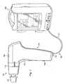
- Fig. 1 illustrates a powered screwdriver system 100 according to an exemplary embodiment of the present invention.
- the system includes a motor powered driver 102 and a control console 104.
- the driver 102 operates at variable rotational velocities to drive taps, drill bits, and surgical hardware, such as, for example, bone screws during a surgical procedure.
- the driver 102 is configured with an electric ratchet.
- the driver 102 includes an outer housing 105 in the shape of a handle 106 and a barrel 108.
- the handle 106 extends from the barrel 108 in a pistol-grip fashion for convenience and comfort of the user.
- the handle 106 includes an electrical port 110 and an input device, here shown as a trigger 112.
- the trigger 112 includes a permanent magnet and a Hall effect sensor. In use, the magnetic field detected by the Hall effect sensor changes based on the relative position of the trigger 112 and the proximity of the magnet within the trigger to the Hall effect sensor.
- the barrel 108 includes a collet 116 and a mode selector 118.
- Other input devices such a torque control level or limit, alignment elements, and other features also may be included.
- the collet 116 is disposed at the working end of the driver 102 and receives a tool, such as a tap, drill bit, driver, socket, or other tool.
- the mode selector 118 is arranged to control the driving direction of the driver 102.
- the available modes include a forward mode, a reverse mode, an oscillating mode, a lock or non-rotation mode, among other modes.
- the mode selector 118 is a collar disposed about a portion of the barrel 108.
- the mode selector 118 is a button, a toggle lever, a rocker switch, or other input device.
- the driver 102 contains a motor for driving the tools at the working end.
- the motor is a brushless DC motor configured to be powered from the control console 102.
- the electrical port 110 connects the driver 102 with the control console 104 through the cable 114.
- the driver and console communicate wirelessly.
- the handle 106 of the driver 102 contains a motor disposed so that the motor shaft extends upwardly from the handle 106 into the barrel 108.
- a gear mechanism connects the motor shaft to a substantially horizontally extending driving shaft connected to the collet 116 and that is utilized to drive a drilling tool or mechanized end received by the driver 102.
- the mode selector 118 includes a collar 120 that includes radially projecting tabs 122 that enable a user to easily rotate the mode selector about a central axis to change driving modes.
- a magnet ring 124 is fixed to and rotates with the collar 120.
- the magnet ring 124 and collar 120 are disposed on a portion of the body 126 of the driver barrel 108, with an insulating layer 128 and Hall effect sensor 130 disposed therein.
- the magnet ring 124 includes a plurality of magnets 132. Rotation of the mode selector 118 displaces the magnets 132 relative to the Hall effect sensor 130.
- the Hall effect sensor 130 generates a signal used to identify the position of the mode selector 118, and likewise, to identify the selected mode.
- the mode selector 118 may communicate a signal representing the mode or the position of the collar to the control console 104.
- Other examples of mode selectors include a single magnet 132 and multiple hall effect sensors 130.
- Other types of sensors are contemplated as being used in place of the Hall effect sensors including, for example, reed sensors and others.
- the mode selector enables a user to select the operating mode of the driver 102.
- the available modes include a forward mode, a reverse mode, an oscillating mode, and a lock or non-rotation mode, among other modes.
- Some designs provide ancillary user inputs not related to shaft control. The location of the magnets relative to the Hall effect sensors provides an indication of the selected mode. This is communicated back to the console 104 for processing and functional implementation.
- control console 104 may include controls and settings for operating the driver 102.
- the control console 104 is configured to receive signals from the driver 102 and control the output of the driver 102 based on those received signals, combined with user settings received directly at the control console. Some examples of this may become apparent from the description below. It is worth noting that some systems do not include a separate control console, and in such embodiments, all determinations and calculations may be performed elsewhere, such as for example, onboard the driver 102 itself.
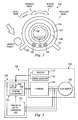
- Fig. 3 shows a block diagram of one example of a system 100 in accordance with an exemplary aspect of the present disclosure.
- the system includes the driver 102 and the control console 104.
- the driver 102 includes the trigger 112, the mode selector 118, an H-bridge 148, and a motor 150.
- the H-bridge 148 directs power from the control console 104 to the motor 150. Depending on the operating mode determined by the mode selector 118, the H-bridge directs power in one direction or the other. For example, if the mode selector 118 is changed from forward mode to reverse mode, the H-bridge redirects power through the motor and switches its operating direction.
- the motor 150 is a brushless DC motor having three windings represented by the three inputs from the H-bridge 148.
- Fig. 4 shows a stylized example of a brushless DC motor in accordance with one aspect of the present disclosure.
- the motor 150 in Fig. 4 is a synchronous motor and includes a stator 160, a rotor 162, and permanent magnets 164 disposed on and rotatable with the rotor 162.
- the motor is a 3-phase motor, although 2-phase and single phase motors may be used in other embodiments.
- the stator 160 includes windings 166.
- the magnets 164 include two pole pairs with alternate north and south poles.
- the example shown is a four pole motor.
- the rotor 162 rotates relative the stator 160.
- the stator is fixed relative to the driver housing 105. Accordingly, when a user physically turns the driver to effect a manual driving of a screw, the stator 160 stays fixed relative to the driver housing 105.
- the motor has a motor housing about the stator 160 fixed in place relative to the driver housing 105.
- control console 104 includes a processing system and memory programmed such that the control console 104 is configured to receive various setting inputs from a user (e.g., maximum speed and maximum torque) and to control the motor of the driver 102 based on the user's setting inputs and depression of the trigger 112 on the driver 102.
- control console 104 of the system 100 provides position control and torque control to the motor of the driver 102.
- control console 104 includes an analog to digital converter (ADC) 152 and a controller 154 that comprises a processor 156 running a position estimation module 158.
- the system 100 also includes memory containing executable programs that influence the manner in which the system 100 operates, a user interface, communication modules, and other standard equipment. In some examples using the control console 104, a user is able to set the maximum speed, acceleration, jerk, and mode (forward, reverse, or oscillate) for the system.
- the processor 156 receives a signal indicative of the amount of depression of the trigger 112. The signal sent to the processor 156 may be indicative of the amount of trigger depression based on the magnetic field sensed by the Hall effect sensor, as indicated above. Also, as indicated above, all signal communication between the driver and the console may be over the cable 114. Alternatively, communication may be wireless Bluetooth, Wi-Fi, conventional RF, infrared, or other communication method.
- the processor 156 is a digital signal processor that receives the various setting inputs from the user. Based on the settings, and particular pre-stored executable programs, the processor controls the H-bridge and sends signals to the H-bridge, which are communicated to the motor 150. For example, using the inputs received with respect to the maximum speed, acceleration, jerk, mode, and trigger position, the controller 154 drives the position of the rotor of the driver 102. The controller 154 outputs a pulse-width modulated control signal that has a duty cycle in accordance with a desired control curve to control the position of the rotor of the motor.
- control console 104 uses the back electromotive force (EMF) from the motor 150 to monitor the rotor position of the motor 150 to ensure that the motor's rotor is achieving the desired positions defined by the control curve. This is accomplished by detecting the EMF level for each winding in its turn at the controller 154.
- EMF signals are sent from the motor to the ADC, which converts the EMF signals to digital signals, which are then communicated to the controller 154.
- the controller 154 adjusts the duty cycle based on an error signal representative of the difference between the actual position of the rotor and the desired position of the rotor. In this manner, the system 100 monitors the position of the rotor to ensure that the rotor is achieving the desired positions during use of the driver 102.
- the stator 160 ( Fig. 4 ) is fixed in place relative to the driver housing 105 ( Fig. 1 ).
- the motor rotor 162 is at least rotatably, mechanically coupled to the drive shaft and collet 116 either directly or through a gear system, for example. Therefore, movement of the rotor 162 relative to the stator 160 is indicative of movement of the collet 116 (and a tool in the collet) relative to the driver housing 105. Accordingly, when the collet 116 and the drive shaft are engaged with a tool, which may be engaged to a screw, the system 100 can detect relative movement between the screw and the driver 102.
- the controller 154 of the system 100 is configured to operate the electric ratchet by receiving data, such as EMF indicative of the rotor position relative to the stator and applying power to the motor at a level sufficient to reduce or prevent further detected relative movement between the rotor and the stator.
- Fig. 5 shows a block diagram of an example of a system 100a in accordance with another exemplary aspect of the present disclosure.
- the system 100a includes the driver 102 and the control console 104.
- the driver 102 includes the trigger 112, the mode selector 118, the H-bridge 148, and the motor 150.
- this embodiment also includes a position sensing element 170.
- the position sensing element 170 may be any device configured to directly identify the position of the rotor in the motor 150.
- the position sensing element 170 is a plurality of Hall effect sensors.
- the Hall effect sensors are disposed in the stator of the motor and are configured to detect the passage of the magnetic poles of the rotor and emit a voltage signal that is passed to the control console 104.
- One example uses three Hall effect sensors. However, greater and smaller numbers of Hall effect sensors are contemplated.
- the control console 104 includes the ADC 152 and the controller 154.
- the controller 154 can receive data directly indicating the position of the rotor, and therefore, the controller need not include a position estimation module 158.
- the ADC 152 converts the voltage signal from the position sensing element 170 to a digital signal and passes it to the controller 154.
- the controller 154 instead of determining position as required by the system 100 in Fig. 3 , the controller 154 directly detects the position of the rotor relative to the stator.
- the controller 154 may then operate the motor 150 based on the position of the rotor to prevent or limit freewheel rotation in one direction while permitting freewheel rotation in the other direction, thereby achieving the ratcheting effect.
- the position sensing element 170 may also be a rotary encoder or other direct position measuring system that will measure the position of the rotor 162 relative to the stator 160.
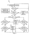
- Fig. 6 shows a logic flow chart performed by the controller 154 to achieve the electric ratchet functionality of the powered screwdriver system 100.
- the logic flow chart is an executable program of a method stored in memory and executable by the processor 156.
- the method referenced by the numeral 200, begins at a step 202 where the processor 156 estimates the current position of the rotor relative to the stator.
- controller 154 monitors EMF from the motor 150, and based on the EMF determines the position of the rotor or where the controller 154 receives signals from Hall effect sensors or encoders associated with the motor that indicate the position of the rotor relative to the stator.
- the controller determines whether the ratchet mode is on or active. In one example, this is accomplished by detecting the position of the mode selector 118. If the mode selector 118 is at a position where the ratcheting mode is active, then a signal is sent from the driver 102 to the control console 104 for processing by the controller 154. The signal permits the controller to operate the system 100 in a ratcheting mode. In some examples, the signal is the absence of alternative signals. In the mode selector 118 described above, the ratcheting mode is active in a forward direction anytime the mode selector 118 is in a forward mode and the trigger is not depressed.
- the ratcheting mode is active in a reverse direction anytime the mode selector 118 is in a reverse mode and the trigger is not depressed.
- the mode selector includes a ratcheting mode independent of the forward and reverse modes. Accordingly, a user may activate or turn on the ratchet mode by moving the mode selector to a ratchet mode.
- Mode selectors may include buttons or switches independent of the mode selector described above, and may be disposed on the console 104 or on the driver 102. If, at step 204, the ratchet mode is not on, then the system cycles in a loop, continuing to estimate the current position of the rotor relative to the current position. In this condition, the driver may still operate in normal functions, permitting forward driving, reverse driving, or oscillating, among other control scenarios.
- the controller 154 determines whether the ratchet was previously on or whether this is the first time through the loop at a step 206. If it is the first time through the loop at step 206, then the loop sets a desired position of the rotor relative the stator. Here, it sets the desired position as equal to the current position at a step 208.
- the step of setting the desired position equal to the current position at step 208 uses the current position that was estimated at step 202. With the desired position set at step 208, the process returns to step 202 and again estimates the current position of the rotor relative to the stator. This estimated current position value is stored for later use.
- the controller 154 determines whether the ratchet is set for forward (clockwise) or reverse (counterclockwise) rotation at step 210.
- the direction of rotation is associated entirely with the setting of the mode selector. For example, if the mode selector is set in a forward mode, then the direction may be set as forward. If the mode selector is set in a reverse mode, then the direction selector may be not set as forward, but instead is set at reverse.
- the system 100 may be configured to ratchet in only a single direction. Accordingly, the direction selector at step 210 may also be a condition for determining whether the ratchet is on and therefore, in some examples may be a part of step 204.
- the method continues from step 210 depending on the direction selected. If the direction is forward at step 210, then the method determines the difference between the desired position and the current position last taken at step 202. This difference is referred to herein as an error value. The error value is then compared to a preset threshold value x to determine whether to use the motor to counter applied loading and use the system as a ratchet.
- the threshold value x is a variable that provides for some movement from the desired position before the motor is activated. In some examples however, the value x is zero or substantially zero.
- step 212 if the error value between the current and the desired positions is greater than the preset value x, then the controller 154 commutates the motor to achieve the desired position at a step 214. Accordingly, as the driver housing begins to displace relative to the collet and driving tool in the driver 102, the error value between the current position and the desired position increases until it exceeds the preset value x. Once the error value is greater than x, the controller 154 controls the motor with power sufficient to effectively offset the torque being applied to maintain the rotor substantially in the desired position relative to the stator. This need not necessarily require bringing the error to zero, but may be include merely limiting or controlling further increases in the error value.
- the motor substantially maintains the rotor position relative to the stator, thereby manually driving the hardware, such as a bone screw.
- the threshold value of x may be in micro degrees, the relative displacement may be imperceptible to a user. In one example, the value of x amounts to less than one degree of relative movement.
- the processor 154 determines at a step 216 whether the error value is less than zero.
- a value less than zero at step 216 indicates that the rotor 162 is being turned in reverse relative to the stator 160. Consistent with conventional mechanical ratchet operation, freewheel rotation in one direction is permitted while rotation in the other direction is not. Accordingly, in this embodiment, the motor is not controlled to limit or prevent rotation in the reverse direction at step 216. Accordingly, if the error value between the current and desired positions is less than zero, then the controller 254 resets the desired position to the detected current position at step 218. This provides a new starting point (desired position).
- step 216 If at step 216, the error value between the current and desired position is not less than zero, but was also not greater than x at step 212, then the controller returns to step 202 and begins the process again.
- the controller 154 determines the error value between the current position and the desired position and compares it to a negative value of x (-x) at step 220. Operation then operates in a manner similar to that described above with reference to steps 212, 214, 216, and 218, but using the opposite direction, resulting in a negative x. That is, if the error value is less than negative x, then the controller 154 controls the motor to maintain the current position at the desired position at step 214. As such, the system effectively limits or prevents relative movement of the driver 102 and the collet or a screwdriver in the collet.
- the controller 154 determines whether the error value is greater than zero at a step 222. If the error value is greater than zero, then at step 218, the desired position it set equal to the current position. If is not greater than zero, then the processor returns to step 202.
- the method 200 described in Fig. 4 is for a system that permits ratcheting in both the forward and rearward directions, depending on the setting. Some embodiments permit ratcheting in only one direction, such as a forward driving direction. In such a system, the steps 220 and 222 may be not present. Because the motor is powered to prevent or limit relative movement between the collet and the driver 102, a user can drive the instrument or tool, whether a screw, a tap, a bit or other instrument or tool, by rotating the driver 102 in a forward direction without depressing the trigger.
- the system 100 is configured so that when the driver is manually rotated in the freewheeled rotation direction, the driver 102 or control console 104 emits a clicking sound.
- the clicking sound may be emitted when the system is in a ratchet mode and the collet displaces relative to the driver body by a preset range of rotation, as measured by the displacement of the rotor relative to the stator.
- the controller 154 is configured to generate a signal that results in a clicking noise one time for every ten degrees of freewheeled rotation.
- the speaker emitting the clicking noise may be disposed on the driver 102 or on the control console 104.
- the PWM of the motor voltage provides audible feedback to the user.
- an audible tone generated by the motor may provide feedback to the user.
- the volume of the audible tone increases, or alternatively, as the torque increases, the pitch (based on frequencies) increases.
- some embodiments of the present disclosure include a driver containing the processing capability that is disclosed herein as being on the control console 104. Accordingly, in some examples, the controller 154 is disposed on the driver itself. Further, although the embodiment shown discloses operating power being drawn from the control console 104, some driver embodiments include their own separate power source, such as a battery power source, using either a rechargeable battery pack or primary batteries. Some embodiments include a power cord pluggable into a conventional power outlet.
- the driver is a surgical tool configured to be used in a surgical setting. Accordingly, the driver may be configured in a manner to be sterilized by an autoclave. Further, the driver may be configured to be entirely self-contained, without vents or releases of material or filaments from the motor that could introduce contamination to a sterile field.
- the freewheel capability of the electric ratchet includes not powering the motor to prevent motor displacement in the second freewheel direction opposite the first, driving direction. Accordingly, a user can freely rotate the driver relative to the screw in the second, opposite direction.
- the freewheel capability of the electric ratchet also provides some small level of motor power to offset drive train drag when the motor is rotated in the second freewheel direction. Accordingly, in some examples, where the drive train drag exceeds the frictional force on the surgical hardware (such as a bone screw), the hardware still will not rotate with the driver in both the first driving and second freewheeling directions.
Landscapes
- Health & Medical Sciences (AREA)
- Engineering & Computer Science (AREA)
- Mechanical Engineering (AREA)
- Life Sciences & Earth Sciences (AREA)
- Orthopedic Medicine & Surgery (AREA)
- Surgery (AREA)
- Power Engineering (AREA)
- Public Health (AREA)
- Heart & Thoracic Surgery (AREA)
- Medical Informatics (AREA)
- Molecular Biology (AREA)
- Animal Behavior & Ethology (AREA)
- General Health & Medical Sciences (AREA)
- Biomedical Technology (AREA)
- Veterinary Medicine (AREA)
- Nuclear Medicine, Radiotherapy & Molecular Imaging (AREA)
- Control Of Electric Motors In General (AREA)
- Control Of Motors That Do Not Use Commutators (AREA)
- Details Of Spanners, Wrenches, And Screw Drivers And Accessories (AREA)
- Devices For Opening Bottles Or Cans (AREA)
Applications Claiming Priority (2)
| Application Number | Priority Date | Filing Date | Title |
|---|---|---|---|
| US13/095,600 US8786233B2 (en) | 2011-04-27 | 2011-04-27 | Electric ratchet for a powered screwdriver |
| PCT/US2012/035004 WO2012149023A1 (en) | 2011-04-27 | 2012-04-25 | Electric ratchet for a powered screwdriver |
Publications (2)
| Publication Number | Publication Date |
|---|---|
| EP2701879A1 EP2701879A1 (en) | 2014-03-05 |
| EP2701879B1 true EP2701879B1 (en) | 2015-09-09 |
Family
ID=46046341
Family Applications (1)
| Application Number | Title | Priority Date | Filing Date |
|---|---|---|---|
| EP12719870.3A Active EP2701879B1 (en) | 2011-04-27 | 2012-04-25 | Electric ratchet for a powered screwdriver |
Country Status (10)
| Country | Link |
|---|---|
| US (2) | US8786233B2 (zh) |
| EP (1) | EP2701879B1 (zh) |
| JP (1) | JP5989764B2 (zh) |
| KR (2) | KR101571328B1 (zh) |
| CN (1) | CN103596730B (zh) |
| AU (1) | AU2012249830B2 (zh) |
| BR (1) | BR112013027796A2 (zh) |
| CA (1) | CA2834582C (zh) |
| ES (1) | ES2555581T3 (zh) |
| WO (1) | WO2012149023A1 (zh) |
Cited By (1)
| Publication number | Priority date | Publication date | Assignee | Title |
|---|---|---|---|---|
| DE102021208359A1 (de) | 2021-08-02 | 2023-02-02 | Adolf Würth GmbH & Co. KG | Schlag- oder Impulsschrauber und Verfahren zum Eindrehen einer Schraube |
Families Citing this family (26)
| Publication number | Priority date | Publication date | Assignee | Title |
|---|---|---|---|---|
| US9358672B2 (en) * | 2010-05-18 | 2016-06-07 | Gauthier Biomedical, Inc. | Electronic torque wrench |
| EP2691213B2 (en) * | 2011-03-31 | 2019-12-04 | Ingersoll-Rand Company | Forward/reverse switching device for power tools |
| US8786233B2 (en) | 2011-04-27 | 2014-07-22 | Medtronic Xomed, Inc. | Electric ratchet for a powered screwdriver |
| US9406457B2 (en) | 2011-05-19 | 2016-08-02 | Black & Decker Inc. | Electronic switching module for a power tool |
| US10245042B2 (en) * | 2012-03-13 | 2019-04-02 | Medtronic Xomed, Inc. | Check valve vented sterilizable powered surgical handpiece |
| US10456122B2 (en) | 2012-03-13 | 2019-10-29 | Medtronic Xomed, Inc. | Surgical system including powered rotary-type handpiece |
| US9987067B2 (en) | 2012-07-11 | 2018-06-05 | Zimmer, Inc. | Bone fixation tool |
| DE102012214975A1 (de) * | 2012-08-23 | 2014-02-27 | Hilti Aktiengesellschaft | Verfahren und Vorrichtung zum Regeln eines Elektromotors einer Handwerkzeugmaschine |
| AU2013347775B2 (en) * | 2012-11-26 | 2018-12-20 | Gauthier Biomedical, Inc. | Electronic torque wrench |
| JP6090581B2 (ja) * | 2013-09-28 | 2017-03-08 | 日立工機株式会社 | 電動工具 |
| US10130382B2 (en) | 2014-03-27 | 2018-11-20 | Medtronic Xomed, Inc. | Powered surgical handpiece having a surgical tool with an RFID tag |
| CN106456225B (zh) * | 2014-04-03 | 2019-02-26 | 捷迈有限公司 | 用于骨固定的整形工具 |
| US9987066B2 (en) | 2014-12-15 | 2018-06-05 | Medos International Sarl | Bone anchor driver and methods |
| JP6697487B2 (ja) * | 2015-06-19 | 2020-05-20 | コヴィディエン リミテッド パートナーシップ | ロボット外科手術アセンブリ |
| DE102015111877A1 (de) | 2015-07-22 | 2017-01-26 | Aesculap Ag | Werkzeugaufnahmeaufsatz für chirurgische Bohrmaschine mit zusätzlicher manueller Antriebseinheit und chirurgische Bohrmaschine |
| DE102015111878A1 (de) | 2015-07-22 | 2017-01-26 | Aesculap Ag | Platzsparende Ratscheinheit mit Freilauf |
| DE102016113934A1 (de) * | 2015-08-18 | 2017-02-23 | Johnson Electric S.A. | Elektrowerkzeug mit bürstenlosem Einphasenmotor |
| KR102156612B1 (ko) * | 2015-09-03 | 2020-09-16 | 닛폰세이테츠 가부시키가이샤 | 구멍 확장 가공 방법, 성형용구, 및 성형 가공품 |
| US9968412B2 (en) | 2016-08-16 | 2018-05-15 | Ethicon Endo-Surgery, Llc | Methods, systems, and devices for controlling a motor of a robotic surgical system |
| US10016246B2 (en) | 2016-08-16 | 2018-07-10 | Ethicon Llc | Methods, systems, and devices for controlling a motor of a robotic surgical system |
| US9956050B2 (en) | 2016-08-16 | 2018-05-01 | Ethicon Endo-Surgery, Llc | Methods, systems, and devices for controlling a motor of a robotic surgical system |
| WO2018156217A2 (en) * | 2016-11-04 | 2018-08-30 | Sommetrics, Inc. | Pressure control system, device and method for opening an airway |
| CN110022100B (zh) * | 2018-01-09 | 2022-04-22 | 博世电动工具(中国)有限公司 | 单相直流无刷电机及其控制设备和控制方法 |
| US11712787B2 (en) | 2018-10-26 | 2023-08-01 | Milwaukee Electric Tool Corporation | Ratcheting tool |
| KR102526695B1 (ko) * | 2020-12-29 | 2023-05-02 | 계양전기 주식회사 | 전자식 라쳇팅 제어 장치 및 그 제어 방법 |
| CN115388140B (zh) * | 2022-09-13 | 2023-05-09 | 天津第一机床有限公司 | 具有准确拨齿结构的棘轮棘爪进给机构 |
Family Cites Families (111)
| Publication number | Priority date | Publication date | Assignee | Title |
|---|---|---|---|---|
| US3734207A (en) | 1971-12-27 | 1973-05-22 | M Fishbein | Battery powered orthopedic cutting tool |
| US4289131A (en) | 1979-05-17 | 1981-09-15 | Ergo Instruments, Inc. | Surgical power tool |
| US4441563A (en) | 1981-11-02 | 1984-04-10 | Black & Decker Inc. | Tool collet and control means |
| US4473226A (en) | 1982-06-29 | 1984-09-25 | Baltimore Therapeutic Equipment Company | Electric ratchet |
| US4635502A (en) | 1985-02-27 | 1987-01-13 | Black & Decker Inc. | Rachet system for hand-held tool |
| JPS62102977A (ja) * | 1985-10-30 | 1987-05-13 | マツダ株式会社 | ナツトランナの自己診断装置 |
| US4728876A (en) | 1986-02-19 | 1988-03-01 | Minnesota Mining And Manufacturing Company | Orthopedic drive assembly |
| US5115175A (en) | 1988-02-03 | 1992-05-19 | Hall Surgical | Drill having alternate mode control |
| US4873461A (en) | 1988-05-13 | 1989-10-10 | Stryker Corporation | Electric motor sterilizable surgical power tool |
| US5142952A (en) | 1990-05-21 | 1992-09-01 | Snap-On Tools Corporation | Ratchet tool |
| US5080983A (en) | 1990-08-16 | 1992-01-14 | Minnesota Mining And Manufacturing Company | Battery |
| US5365155A (en) | 1990-10-22 | 1994-11-15 | Marquardt Gmbh | Rotational speed control and use of same to control the rotational speed of an electric hand tool motor |
| US5136220A (en) | 1991-06-27 | 1992-08-04 | Stryker Corporation | DC powered surgical handpiece having a motor control circuit |
| US5207697A (en) | 1991-06-27 | 1993-05-04 | Stryker Corporation | Battery powered surgical handpiece |
| US5268622A (en) | 1991-06-27 | 1993-12-07 | Stryker Corporation | DC powered surgical handpiece having a motor control circuit |
| US5136469A (en) | 1991-07-17 | 1992-08-04 | Stryker Corporation | Powered surgical handpiece incorporating sealed multi semiconductor motor control package |
| US5264783A (en) | 1992-01-21 | 1993-11-23 | Allegro Microsystems, Inc. | Contactless magnet-activated proportional controller |
| US5474558A (en) | 1992-04-30 | 1995-12-12 | Neubardt; Seth L. | Procedure and system for spinal pedicle screw insertion |
| US5196015A (en) | 1992-04-30 | 1993-03-23 | Neubardt Seth L | Procedure for spinal pedicle screw insertion |
| US6424799B1 (en) * | 1993-07-06 | 2002-07-23 | Black & Decker Inc. | Electrical power tool having a motor control circuit for providing control over the torque output of the power tool |
| US5553675A (en) | 1994-06-10 | 1996-09-10 | Minnesota Mining And Manufacturing Company | Orthopedic surgical device |
| USD364463S (en) | 1994-06-10 | 1995-11-21 | Minnesota Mining And Manufacturing Company | Orthopedic surgical instrument |
| US5625273A (en) | 1994-12-30 | 1997-04-29 | Bren-Tronics Inc. | Battery safety device |
| US5670749A (en) | 1995-09-29 | 1997-09-23 | Allen-Bradley Company, Inc. | Multilayer circuit board having a window exposing an enhanced conductive layer for use as an insulated mounting area |
| JPH09106804A (ja) | 1995-10-09 | 1997-04-22 | Wako Denshi Kk | 電池の安全装置 |
| US5712543A (en) | 1995-10-31 | 1998-01-27 | Smith & Nephew Endoscopy Inc. | Magnetic switching element for controlling a surgical device |
| US5804936A (en) | 1995-10-31 | 1998-09-08 | Smith & Nephew, Inc. | Motor controlled surgical system |
| US5697158A (en) | 1995-12-21 | 1997-12-16 | Minnesota Mining And Manufacturing Company | Orthopedic surgical device having a rotatable portion and lock |
| AUPN741996A0 (en) | 1996-01-04 | 1996-01-25 | Interfix Limited | A driver |
| DE19607123C2 (de) | 1996-02-26 | 1998-07-16 | Aesculap Ag & Co Kg | Bohrmaschine für chirurgische Zwecke |
| US5941876A (en) | 1996-03-11 | 1999-08-24 | Medical Scientific, Inc. | Electrosurgical rotating cutting device |
| US5747953A (en) | 1996-03-29 | 1998-05-05 | Stryker Corporation | Cordless, battery operated surical tool |
| US6017354A (en) | 1996-08-15 | 2000-01-25 | Stryker Corporation | Integrated system for powered surgical tools |
| JPH10100079A (ja) | 1996-09-30 | 1998-04-21 | Sanyo Electric Co Ltd | 電動工具用のパック電池 |
| US5928158A (en) | 1997-03-25 | 1999-07-27 | Aristides; Arellano | Medical instrument with nerve sensor |
| US6037724A (en) | 1997-05-01 | 2000-03-14 | Osteomed Corporation | Electronic controlled surgical power tool |
| US5976720A (en) | 1997-06-13 | 1999-11-02 | Comtec Information Systems Inc | Short circuit and overcharge protected battery pack |
| JPH1154110A (ja) | 1997-07-31 | 1999-02-26 | N Ii C Mori Energ Kk | 正特性温度素子を備えた電池保護装置 |
| GB9718305D0 (en) | 1997-08-30 | 1997-11-05 | Black & Decker Inc | Power tool |
| US6391005B1 (en) | 1998-03-30 | 2002-05-21 | Agilent Technologies, Inc. | Apparatus and method for penetration with shaft having a sensor for sensing penetration depth |
| DE19856627A1 (de) * | 1998-12-08 | 2000-06-15 | Dt Swiss Ag Biel | Freilaufnabe |
| US6564078B1 (en) | 1998-12-23 | 2003-05-13 | Nuvasive, Inc. | Nerve surveillance cannula systems |
| FR2788382B1 (fr) | 1999-01-07 | 2001-03-30 | Cit Alcatel | Protection pour module de batterie avec memorisation par diode |
| DE10011233B4 (de) | 1999-03-12 | 2007-07-12 | Sanyo Electric Co., Ltd., Moriguchi | Batterieeinheit |
| US6193715B1 (en) | 1999-03-19 | 2001-02-27 | Medical Scientific, Inc. | Device for converting a mechanical cutting device to an electrosurgical cutting device |
| FR2795624B1 (fr) | 1999-07-01 | 2001-09-28 | Vanacker Gerard | Procede de forage du pedicule vertebral notamment pour la mise en place d'une vis pediculaire, instrument pour la mise en oeuvre d'un tel procede |
| US6199642B1 (en) | 1999-07-06 | 2001-03-13 | Snap-On Tools Company | Reversible ratcheting power tool with synchronized motor and ratchet control |
| US6499488B1 (en) | 1999-10-28 | 2002-12-31 | Winchester Development Associates | Surgical sensor |
| US6244358B1 (en) | 2000-01-13 | 2001-06-12 | Snap-On Technologies, Inc. | Trigger and clutch arrangement for power tools |
| US6443675B1 (en) | 2000-02-17 | 2002-09-03 | Roto Zip Tool Corporation | Hand-held power tool |
| EP1146579B1 (en) | 2000-04-12 | 2011-06-08 | Panasonic Corporation | Non-aqueous electrolyte rechargeable battery |
| US6945981B2 (en) | 2000-10-20 | 2005-09-20 | Ethicon-Endo Surgery, Inc. | Finger operated switch for controlling a surgical handpiece |
| US6602260B2 (en) | 2001-02-02 | 2003-08-05 | Ams Research Corporation | Powered bone screw device |
| DE10212721A1 (de) | 2001-03-24 | 2002-09-26 | Marquardt Gmbh | Ansteuereinrichtung für einen Elektromotor |
| JP3609741B2 (ja) | 2001-03-30 | 2005-01-12 | 三洋電機株式会社 | パック電池 |
| US7664544B2 (en) | 2002-10-30 | 2010-02-16 | Nuvasive, Inc. | System and methods for performing percutaneous pedicle integrity assessments |
| US6512348B1 (en) | 2001-11-29 | 2003-01-28 | Bioplate, Inc. | Battery aligner insertion apparatus and method |
| FR2835732B1 (fr) | 2002-02-11 | 2004-11-12 | Spinevision | Dispositif permettant le suivi de la penetration d'un moyen de penetration dans des elements anatomiques |
| US7582058B1 (en) | 2002-06-26 | 2009-09-01 | Nuvasive, Inc. | Surgical access system and related methods |
| US6960894B2 (en) | 2002-08-01 | 2005-11-01 | Stryker Corporation | Cordless, powered surgical tool |
| US6805208B2 (en) | 2002-08-02 | 2004-10-19 | Black & Decker Inc. | Switch lock-off mechanism for power tools |
| US7887559B2 (en) | 2002-08-08 | 2011-02-15 | Stryker Corporation | Surgical cutting accessory with encapsulated RFID chip |
| JP2004082222A (ja) * | 2002-08-22 | 2004-03-18 | Denso Corp | 電動ドライバー |
| US6741051B2 (en) | 2002-08-30 | 2004-05-25 | Defond Manufacturing Limited | Power tool trigger control |
| GB0226523D0 (en) | 2002-11-14 | 2002-12-18 | Black & Decker Inc | Electric motor driven hand-held tool |
| JP4601903B2 (ja) | 2003-01-27 | 2010-12-22 | パナソニック株式会社 | 電池パック |
| US6819083B1 (en) | 2003-04-25 | 2004-11-16 | Motorola, Inc. | Dual use thermistor for battery cell thermal protection and battery pack overcharge/undercharge protection |
| US9504477B2 (en) | 2003-05-30 | 2016-11-29 | Vidacare LLC | Powered driver |
| WO2005000090A2 (en) | 2003-05-30 | 2005-01-06 | Medi-Screw, Inc. | Medical implant systems |
| US7749251B2 (en) | 2003-06-13 | 2010-07-06 | Aeolin, Llc | Method and apparatus for stabilization of facet joint |
| US6960208B2 (en) | 2003-06-30 | 2005-11-01 | Boston Scientific Scimed, Inc. | Apparatus and methods for delivering energy to a target site within bone |
| JP4436836B2 (ja) | 2003-08-05 | 2010-03-24 | ヌヴァシヴ インコーポレイテッド | 動的なペディクルの完全性評価を実行するシステム及び方法 |
| JP4463819B2 (ja) | 2003-09-25 | 2010-05-19 | ヌヴァシヴ インコーポレイテッド | 外科手術接近システム |
| US7270910B2 (en) | 2003-10-03 | 2007-09-18 | Black & Decker Inc. | Thermal management systems for battery packs |
| JP2008541784A (ja) | 2004-03-30 | 2008-11-27 | キナメッド・インコーポレーテッド | 手術用電動ねじ回し |
| USD534651S1 (en) | 2004-04-01 | 2007-01-02 | Kinamed, Inc. | Powered surgical screwdriver |
| JP4509662B2 (ja) | 2004-06-16 | 2010-07-21 | 株式会社マキタ | 電動打撃工具 |
| WO2006008057A1 (de) | 2004-07-15 | 2006-01-26 | Marquardt Gmbh | Elektrowerkzeug, insbesondere akku-elektrowerkzeug |
| JP4823499B2 (ja) * | 2004-07-23 | 2011-11-24 | 勝行 戸津 | ブラシレスモータ駆動回転工具の制御方法 |
| DE102004038414A1 (de) | 2004-07-30 | 2006-03-23 | Aesculap Ag & Co. Kg | Chirurgische Maschine und Verfahren zum Betreiben einer chirurgischen Maschine |
| DE102004038415A1 (de) | 2004-07-30 | 2006-03-23 | Aesculap Ag & Co. Kg | Chirurgische Maschine und Verfahren zum Steuern und/oder Regeln einer chirurgischen Maschine |
| US7598696B2 (en) | 2004-08-31 | 2009-10-06 | Medtronic, Inc. | Surgical apparatus including a hand-activated, control assembly and method of using same |
| US7210542B2 (en) | 2004-09-23 | 2007-05-01 | Defond Components Limited | Power tool safety device |
| US7422582B2 (en) | 2004-09-29 | 2008-09-09 | Stryker Corporation | Control console to which powered surgical handpieces are connected, the console configured to simultaneously energize more than one and less than all of the handpieces |
| US7643861B2 (en) | 2005-01-18 | 2010-01-05 | John Richard Ives | Technique for design, and placement, of a subdermal Ag—Ag/Cl biopotential electrode |
| US7878981B2 (en) | 2005-03-01 | 2011-02-01 | Checkpoint Surgical, Llc | Systems and methods for intra-operative stimulation |
| US7896815B2 (en) | 2005-03-01 | 2011-03-01 | Checkpoint Surgical, Llc | Systems and methods for intra-operative stimulation |
| US20060200023A1 (en) | 2005-03-04 | 2006-09-07 | Sdgi Holdings, Inc. | Instruments and methods for nerve monitoring in spinal surgical procedures |
| JP4892546B2 (ja) * | 2005-04-16 | 2012-03-07 | アエスキュラップ アーゲー | 外科用機械及び外科用機械の制御及び/又は調整方法 |
| US7677844B2 (en) * | 2005-04-19 | 2010-03-16 | Black & Decker Inc. | Electronic clutch for tool chuck with power take off and dead spindle features |
| JP5044551B2 (ja) | 2005-06-28 | 2012-10-10 | ストライカー・コーポレイション | 器具発電ユニットを遠隔的に監視するためのセンサを含む制御モジュール付き電動外科用器具 |
| US20070010821A1 (en) | 2005-06-29 | 2007-01-11 | Wilkinson Trent R | Screwdriver, kit and associated method |
| US20070010816A1 (en) | 2005-06-29 | 2007-01-11 | Wilkinson Trent R | Tool driver, coupler and associated method |
| EP1780867B1 (en) * | 2005-10-28 | 2016-11-30 | Black & Decker Inc. | Battery pack for cordless power tools |
| US7406899B2 (en) | 2006-07-24 | 2008-08-05 | Walker Douglas W | Automatic feed medical screwdriver |
| US7987001B2 (en) | 2007-01-25 | 2011-07-26 | Warsaw Orthopedic, Inc. | Surgical navigational and neuromonitoring instrument |
| WO2008124463A2 (en) | 2007-04-04 | 2008-10-16 | Vidacare Corporation | Powered drivers, intraosseous devices and methods to access bone marrow |
| US8075601B2 (en) | 2007-04-30 | 2011-12-13 | Warsaw Orthopedic, Inc. | Deformity correction using neural integrity monitoring |
| US20080281332A1 (en) | 2007-05-07 | 2008-11-13 | Warsaw Orthopedic, Inc. | Surgical screwdriver |
| JP5115904B2 (ja) * | 2007-09-21 | 2013-01-09 | 日立工機株式会社 | インパクト工具 |
| US20090088770A1 (en) | 2007-10-01 | 2009-04-02 | Warsaw Orthopedic, Inc. | Angled surgical drivers and methods of use |
| WO2009049367A1 (en) * | 2007-10-19 | 2009-04-23 | Whitehot Solutions Pty Ltd | Multiple chuck hand tool |
| JP5182562B2 (ja) * | 2008-02-29 | 2013-04-17 | 日立工機株式会社 | 電動工具 |
| US20090254094A1 (en) | 2008-04-08 | 2009-10-08 | Knapp Troy D | Ratcheting mechanical driver for cannulated surgical systems |
| US9078671B2 (en) | 2008-04-17 | 2015-07-14 | Warsaw Orthopedic, Inc. | Surgical tool |
| US20090299439A1 (en) * | 2008-06-02 | 2009-12-03 | Warsaw Orthopedic, Inc. | Method, system and tool for surgical procedures |
| ITMI20090225A1 (it) | 2009-02-19 | 2010-08-20 | Studio A I P S R L | Dispositivo avvitatore per applicazioni medicali, in particolare per implantologia endossea |
| KR20100111821A (ko) | 2009-04-08 | 2010-10-18 | 박상수 | 의료용 전동공구 |
| CN101596711A (zh) * | 2009-07-10 | 2009-12-09 | 宁波中港工具有限公司 | 充电式多功能电动工具 |
| JP5686236B2 (ja) | 2010-07-30 | 2015-03-18 | 日立工機株式会社 | 電動工具及びネジ締め用電動工具 |
| US8786233B2 (en) | 2011-04-27 | 2014-07-22 | Medtronic Xomed, Inc. | Electric ratchet for a powered screwdriver |
-
2011
- 2011-04-27 US US13/095,600 patent/US8786233B2/en active Active
-
2012
- 2012-04-25 AU AU2012249830A patent/AU2012249830B2/en active Active
- 2012-04-25 CA CA2834582A patent/CA2834582C/en active Active
- 2012-04-25 KR KR1020137030643A patent/KR101571328B1/ko active IP Right Grant
- 2012-04-25 CN CN201280028229.5A patent/CN103596730B/zh active Active
- 2012-04-25 BR BR112013027796A patent/BR112013027796A2/pt active Search and Examination
- 2012-04-25 ES ES12719870.3T patent/ES2555581T3/es active Active
- 2012-04-25 EP EP12719870.3A patent/EP2701879B1/en active Active
- 2012-04-25 WO PCT/US2012/035004 patent/WO2012149023A1/en active Application Filing
- 2012-04-25 JP JP2014508517A patent/JP5989764B2/ja not_active Expired - Fee Related
- 2012-04-25 KR KR1020157032880A patent/KR101767176B1/ko active IP Right Grant
-
2014
- 2014-07-21 US US14/336,289 patent/US9408653B2/en active Active
Cited By (1)
| Publication number | Priority date | Publication date | Assignee | Title |
|---|---|---|---|---|
| DE102021208359A1 (de) | 2021-08-02 | 2023-02-02 | Adolf Würth GmbH & Co. KG | Schlag- oder Impulsschrauber und Verfahren zum Eindrehen einer Schraube |
Also Published As
| Publication number | Publication date |
|---|---|
| CN103596730B (zh) | 2016-04-13 |
| US20120274253A1 (en) | 2012-11-01 |
| AU2012249830A1 (en) | 2013-11-14 |
| KR20150138397A (ko) | 2015-12-09 |
| ES2555581T3 (es) | 2016-01-05 |
| US9408653B2 (en) | 2016-08-09 |
| BR112013027796A2 (pt) | 2017-01-10 |
| CA2834582A1 (en) | 2012-11-01 |
| CA2834582C (en) | 2015-10-06 |
| KR20140021011A (ko) | 2014-02-19 |
| EP2701879A1 (en) | 2014-03-05 |
| JP2014517774A (ja) | 2014-07-24 |
| JP5989764B2 (ja) | 2016-09-07 |
| KR101571328B1 (ko) | 2015-11-24 |
| WO2012149023A1 (en) | 2012-11-01 |
| AU2012249830B2 (en) | 2016-05-05 |
| US20140327382A1 (en) | 2014-11-06 |
| CN103596730A (zh) | 2014-02-19 |
| US8786233B2 (en) | 2014-07-22 |
| KR101767176B1 (ko) | 2017-08-10 |
Similar Documents
| Publication | Publication Date | Title |
|---|---|---|
| EP2701879B1 (en) | Electric ratchet for a powered screwdriver | |
| JP7275157B2 (ja) | センサ及び/又は制御システムを有する外科用器具 | |
| EP2467239B1 (en) | Power tool | |
| EP2576146B1 (en) | Power tool | |
| JP2021501014A (ja) | 複数のエンドエフェクタ機能を選択的に作動させる回転駆動部を有する外科用器具 | |
| JP2014517774A5 (zh) | ||
| EP2467237A1 (en) | Power tool | |
| KR20200043426A (ko) | 킥백 발생 동안 사용자에게 촉각 피드백을 공급하기 위한 휴대형 외과기구 및 방법 | |
| EP3520968A1 (en) | System for managing a power tool | |
| EP3552768A1 (en) | Power tool and method for controlling a power tool | |
| JP2023055528A (ja) | 電動工具 | |
| JP6484918B2 (ja) | 電動作業機 | |
| AU2021286280B2 (en) | Controlling brushless motor commutation | |
| US9312795B2 (en) | Electric power tool | |
| US20230311293A1 (en) | Electric tool | |
| KR20200104526A (ko) | 일체형의 일회용 드릴 핸드피스 | |
| JP2021016603A (ja) | 歯科用医療装置 | |
| JP2021016602A (ja) | 歯科用医療装置 |
Legal Events
| Date | Code | Title | Description |
|---|---|---|---|
| PUAI | Public reference made under article 153(3) epc to a published international application that has entered the european phase |
Free format text: ORIGINAL CODE: 0009012 |
|
| 17P | Request for examination filed |
Effective date: 20131029 |
|
| AK | Designated contracting states |
Kind code of ref document: A1 Designated state(s): AL AT BE BG CH CY CZ DE DK EE ES FI FR GB GR HR HU IE IS IT LI LT LU LV MC MK MT NL NO PL PT RO RS SE SI SK SM TR |
|
| DAX | Request for extension of the european patent (deleted) | ||
| GRAP | Despatch of communication of intention to grant a patent |
Free format text: ORIGINAL CODE: EPIDOSNIGR1 |
|
| INTG | Intention to grant announced |
Effective date: 20150408 |
|
| GRAS | Grant fee paid |
Free format text: ORIGINAL CODE: EPIDOSNIGR3 |
|
| GRAA | (expected) grant |
Free format text: ORIGINAL CODE: 0009210 |
|
| AK | Designated contracting states |
Kind code of ref document: B1 Designated state(s): AL AT BE BG CH CY CZ DE DK EE ES FI FR GB GR HR HU IE IS IT LI LT LU LV MC MK MT NL NO PL PT RO RS SE SI SK SM TR |
|
| REG | Reference to a national code |
Ref country code: GB Ref legal event code: FG4D |
|
| REG | Reference to a national code |
Ref country code: AT Ref legal event code: REF Ref document number: 747732 Country of ref document: AT Kind code of ref document: T Effective date: 20150915 Ref country code: CH Ref legal event code: EP |
|
| REG | Reference to a national code |
Ref country code: IE Ref legal event code: FG4D |
|
| REG | Reference to a national code |
Ref country code: DE Ref legal event code: R096 Ref document number: 602012010332 Country of ref document: DE |
|
| REG | Reference to a national code |
Ref country code: ES Ref legal event code: FG2A Ref document number: 2555581 Country of ref document: ES Kind code of ref document: T3 Effective date: 20160105 |
|
| PG25 | Lapsed in a contracting state [announced via postgrant information from national office to epo] |
Ref country code: FI Free format text: LAPSE BECAUSE OF FAILURE TO SUBMIT A TRANSLATION OF THE DESCRIPTION OR TO PAY THE FEE WITHIN THE PRESCRIBED TIME-LIMIT Effective date: 20150909 Ref country code: LT Free format text: LAPSE BECAUSE OF FAILURE TO SUBMIT A TRANSLATION OF THE DESCRIPTION OR TO PAY THE FEE WITHIN THE PRESCRIBED TIME-LIMIT Effective date: 20150909 Ref country code: GR Free format text: LAPSE BECAUSE OF FAILURE TO SUBMIT A TRANSLATION OF THE DESCRIPTION OR TO PAY THE FEE WITHIN THE PRESCRIBED TIME-LIMIT Effective date: 20151210 Ref country code: LV Free format text: LAPSE BECAUSE OF FAILURE TO SUBMIT A TRANSLATION OF THE DESCRIPTION OR TO PAY THE FEE WITHIN THE PRESCRIBED TIME-LIMIT Effective date: 20150909 Ref country code: NO Free format text: LAPSE BECAUSE OF FAILURE TO SUBMIT A TRANSLATION OF THE DESCRIPTION OR TO PAY THE FEE WITHIN THE PRESCRIBED TIME-LIMIT Effective date: 20151209 |
|
| REG | Reference to a national code |
Ref country code: LT Ref legal event code: MG4D Ref country code: NL Ref legal event code: FP |
|
| REG | Reference to a national code |
Ref country code: AT Ref legal event code: MK05 Ref document number: 747732 Country of ref document: AT Kind code of ref document: T Effective date: 20150909 |
|
| PG25 | Lapsed in a contracting state [announced via postgrant information from national office to epo] |
Ref country code: HR Free format text: LAPSE BECAUSE OF FAILURE TO SUBMIT A TRANSLATION OF THE DESCRIPTION OR TO PAY THE FEE WITHIN THE PRESCRIBED TIME-LIMIT Effective date: 20150909 Ref country code: SE Free format text: LAPSE BECAUSE OF FAILURE TO SUBMIT A TRANSLATION OF THE DESCRIPTION OR TO PAY THE FEE WITHIN THE PRESCRIBED TIME-LIMIT Effective date: 20150909 Ref country code: RS Free format text: LAPSE BECAUSE OF FAILURE TO SUBMIT A TRANSLATION OF THE DESCRIPTION OR TO PAY THE FEE WITHIN THE PRESCRIBED TIME-LIMIT Effective date: 20150909 |
|
| REG | Reference to a national code |
Ref country code: FR Ref legal event code: PLFP Year of fee payment: 5 |
|
| PG25 | Lapsed in a contracting state [announced via postgrant information from national office to epo] |
Ref country code: SK Free format text: LAPSE BECAUSE OF FAILURE TO SUBMIT A TRANSLATION OF THE DESCRIPTION OR TO PAY THE FEE WITHIN THE PRESCRIBED TIME-LIMIT Effective date: 20150909 Ref country code: IS Free format text: LAPSE BECAUSE OF FAILURE TO SUBMIT A TRANSLATION OF THE DESCRIPTION OR TO PAY THE FEE WITHIN THE PRESCRIBED TIME-LIMIT Effective date: 20160109 Ref country code: CZ Free format text: LAPSE BECAUSE OF FAILURE TO SUBMIT A TRANSLATION OF THE DESCRIPTION OR TO PAY THE FEE WITHIN THE PRESCRIBED TIME-LIMIT Effective date: 20150909 Ref country code: EE Free format text: LAPSE BECAUSE OF FAILURE TO SUBMIT A TRANSLATION OF THE DESCRIPTION OR TO PAY THE FEE WITHIN THE PRESCRIBED TIME-LIMIT Effective date: 20150909 Ref country code: IT Free format text: LAPSE BECAUSE OF FAILURE TO SUBMIT A TRANSLATION OF THE DESCRIPTION OR TO PAY THE FEE WITHIN THE PRESCRIBED TIME-LIMIT Effective date: 20150909 |
|
| PG25 | Lapsed in a contracting state [announced via postgrant information from national office to epo] |
Ref country code: PT Free format text: LAPSE BECAUSE OF FAILURE TO SUBMIT A TRANSLATION OF THE DESCRIPTION OR TO PAY THE FEE WITHIN THE PRESCRIBED TIME-LIMIT Effective date: 20160111 Ref country code: AT Free format text: LAPSE BECAUSE OF FAILURE TO SUBMIT A TRANSLATION OF THE DESCRIPTION OR TO PAY THE FEE WITHIN THE PRESCRIBED TIME-LIMIT Effective date: 20150909 Ref country code: RO Free format text: LAPSE BECAUSE OF FAILURE TO SUBMIT A TRANSLATION OF THE DESCRIPTION OR TO PAY THE FEE WITHIN THE PRESCRIBED TIME-LIMIT Effective date: 20150909 Ref country code: PL Free format text: LAPSE BECAUSE OF FAILURE TO SUBMIT A TRANSLATION OF THE DESCRIPTION OR TO PAY THE FEE WITHIN THE PRESCRIBED TIME-LIMIT Effective date: 20150909 |
|
| REG | Reference to a national code |
Ref country code: DE Ref legal event code: R097 Ref document number: 602012010332 Country of ref document: DE |
|
| PLBE | No opposition filed within time limit |
Free format text: ORIGINAL CODE: 0009261 |
|
| STAA | Information on the status of an ep patent application or granted ep patent |
Free format text: STATUS: NO OPPOSITION FILED WITHIN TIME LIMIT |
|
| 26N | No opposition filed |
Effective date: 20160610 |
|
| PG25 | Lapsed in a contracting state [announced via postgrant information from national office to epo] |
Ref country code: SI Free format text: LAPSE BECAUSE OF FAILURE TO SUBMIT A TRANSLATION OF THE DESCRIPTION OR TO PAY THE FEE WITHIN THE PRESCRIBED TIME-LIMIT Effective date: 20150909 Ref country code: DK Free format text: LAPSE BECAUSE OF FAILURE TO SUBMIT A TRANSLATION OF THE DESCRIPTION OR TO PAY THE FEE WITHIN THE PRESCRIBED TIME-LIMIT Effective date: 20150909 Ref country code: BE Free format text: LAPSE BECAUSE OF NON-PAYMENT OF DUE FEES Effective date: 20160430 |
|
| REG | Reference to a national code |
Ref country code: CH Ref legal event code: PL |
|
| REG | Reference to a national code |
Ref country code: NL Ref legal event code: MM Effective date: 20160501 |
|
| GBPC | Gb: european patent ceased through non-payment of renewal fee |
Effective date: 20160425 |
|
| PG25 | Lapsed in a contracting state [announced via postgrant information from national office to epo] |
Ref country code: BE Free format text: LAPSE BECAUSE OF FAILURE TO SUBMIT A TRANSLATION OF THE DESCRIPTION OR TO PAY THE FEE WITHIN THE PRESCRIBED TIME-LIMIT Effective date: 20150909 Ref country code: LU Free format text: LAPSE BECAUSE OF FAILURE TO SUBMIT A TRANSLATION OF THE DESCRIPTION OR TO PAY THE FEE WITHIN THE PRESCRIBED TIME-LIMIT Effective date: 20160425 |
|
| REG | Reference to a national code |
Ref country code: IE Ref legal event code: MM4A |
|
| PG25 | Lapsed in a contracting state [announced via postgrant information from national office to epo] |
Ref country code: CH Free format text: LAPSE BECAUSE OF NON-PAYMENT OF DUE FEES Effective date: 20160430 Ref country code: NL Free format text: LAPSE BECAUSE OF NON-PAYMENT OF DUE FEES Effective date: 20160501 Ref country code: GB Free format text: LAPSE BECAUSE OF NON-PAYMENT OF DUE FEES Effective date: 20160425 Ref country code: LI Free format text: LAPSE BECAUSE OF NON-PAYMENT OF DUE FEES Effective date: 20160430 |
|
| REG | Reference to a national code |
Ref country code: FR Ref legal event code: PLFP Year of fee payment: 6 |
|
| PG25 | Lapsed in a contracting state [announced via postgrant information from national office to epo] |
Ref country code: IE Free format text: LAPSE BECAUSE OF NON-PAYMENT OF DUE FEES Effective date: 20160425 |
|
| REG | Reference to a national code |
Ref country code: FR Ref legal event code: PLFP Year of fee payment: 7 |
|
| PG25 | Lapsed in a contracting state [announced via postgrant information from national office to epo] |
Ref country code: SM Free format text: LAPSE BECAUSE OF FAILURE TO SUBMIT A TRANSLATION OF THE DESCRIPTION OR TO PAY THE FEE WITHIN THE PRESCRIBED TIME-LIMIT Effective date: 20150909 Ref country code: CY Free format text: LAPSE BECAUSE OF FAILURE TO SUBMIT A TRANSLATION OF THE DESCRIPTION OR TO PAY THE FEE WITHIN THE PRESCRIBED TIME-LIMIT Effective date: 20150909 Ref country code: HU Free format text: LAPSE BECAUSE OF FAILURE TO SUBMIT A TRANSLATION OF THE DESCRIPTION OR TO PAY THE FEE WITHIN THE PRESCRIBED TIME-LIMIT; INVALID AB INITIO Effective date: 20120425 Ref country code: ES Free format text: LAPSE BECAUSE OF NON-PAYMENT OF DUE FEES Effective date: 20160426 |
|
| REG | Reference to a national code |
Ref country code: ES Ref legal event code: FD2A Effective date: 20180625 |
|
| PG25 | Lapsed in a contracting state [announced via postgrant information from national office to epo] |
Ref country code: MK Free format text: LAPSE BECAUSE OF FAILURE TO SUBMIT A TRANSLATION OF THE DESCRIPTION OR TO PAY THE FEE WITHIN THE PRESCRIBED TIME-LIMIT Effective date: 20150909 Ref country code: MC Free format text: LAPSE BECAUSE OF FAILURE TO SUBMIT A TRANSLATION OF THE DESCRIPTION OR TO PAY THE FEE WITHIN THE PRESCRIBED TIME-LIMIT Effective date: 20150909 Ref country code: TR Free format text: LAPSE BECAUSE OF FAILURE TO SUBMIT A TRANSLATION OF THE DESCRIPTION OR TO PAY THE FEE WITHIN THE PRESCRIBED TIME-LIMIT Effective date: 20150909 Ref country code: MT Free format text: LAPSE BECAUSE OF NON-PAYMENT OF DUE FEES Effective date: 20160430 |
|
| PG25 | Lapsed in a contracting state [announced via postgrant information from national office to epo] |
Ref country code: BG Free format text: LAPSE BECAUSE OF FAILURE TO SUBMIT A TRANSLATION OF THE DESCRIPTION OR TO PAY THE FEE WITHIN THE PRESCRIBED TIME-LIMIT Effective date: 20150909 |
|
| PG25 | Lapsed in a contracting state [announced via postgrant information from national office to epo] |
Ref country code: AL Free format text: LAPSE BECAUSE OF FAILURE TO SUBMIT A TRANSLATION OF THE DESCRIPTION OR TO PAY THE FEE WITHIN THE PRESCRIBED TIME-LIMIT Effective date: 20150909 |
|
| PGFP | Annual fee paid to national office [announced via postgrant information from national office to epo] |
Ref country code: FR Payment date: 20230321 Year of fee payment: 12 |
|
| PGFP | Annual fee paid to national office [announced via postgrant information from national office to epo] |
Ref country code: DE Payment date: 20230321 Year of fee payment: 12 |