EP2701014B1 - Kupplungsvorrichtung für Uhrmechanismus - Google Patents
Kupplungsvorrichtung für Uhrmechanismus Download PDFInfo
- Publication number
- EP2701014B1 EP2701014B1 EP13181020.2A EP13181020A EP2701014B1 EP 2701014 B1 EP2701014 B1 EP 2701014B1 EP 13181020 A EP13181020 A EP 13181020A EP 2701014 B1 EP2701014 B1 EP 2701014B1
- Authority
- EP
- European Patent Office
- Prior art keywords
- wheel
- lever
- rotation
- designed
- mobile
- Prior art date
- Legal status (The legal status is an assumption and is not a legal conclusion. Google has not performed a legal analysis and makes no representation as to the accuracy of the status listed.)
- Active
Links
Images


Classifications
-
- G—PHYSICS
- G04—HOROLOGY
- G04B—MECHANICALLY-DRIVEN CLOCKS OR WATCHES; MECHANICAL PARTS OF CLOCKS OR WATCHES IN GENERAL; TIME PIECES USING THE POSITION OF THE SUN, MOON OR STARS
- G04B11/00—Click devices; Stop clicks; Clutches
- G04B11/001—Clutch mechanism between two rotating members with transfer of movement in both directions, possibly with limitation on the transfer of power
- G04B11/003—Clutch mechanism between two rotating members with transfer of movement in both directions, possibly with limitation on the transfer of power with friction member, e.g. with spring action
-
- F—MECHANICAL ENGINEERING; LIGHTING; HEATING; WEAPONS; BLASTING
- F16—ENGINEERING ELEMENTS AND UNITS; GENERAL MEASURES FOR PRODUCING AND MAINTAINING EFFECTIVE FUNCTIONING OF MACHINES OR INSTALLATIONS; THERMAL INSULATION IN GENERAL
- F16H—GEARING
- F16H57/00—General details of gearing
- F16H57/02—Gearboxes; Mounting gearing therein
- F16H57/021—Shaft support structures, e.g. partition walls, bearing eyes, casing walls or covers with bearings
-
- G—PHYSICS
- G04—HOROLOGY
- G04B—MECHANICALLY-DRIVEN CLOCKS OR WATCHES; MECHANICAL PARTS OF CLOCKS OR WATCHES IN GENERAL; TIME PIECES USING THE POSITION OF THE SUN, MOON OR STARS
- G04B13/00—Gearwork
-
- G—PHYSICS
- G04—HOROLOGY
- G04B—MECHANICALLY-DRIVEN CLOCKS OR WATCHES; MECHANICAL PARTS OF CLOCKS OR WATCHES IN GENERAL; TIME PIECES USING THE POSITION OF THE SUN, MOON OR STARS
- G04B13/00—Gearwork
- G04B13/02—Wheels; Pinions; Spindles; Pivots
-
- G—PHYSICS
- G04—HOROLOGY
- G04B—MECHANICALLY-DRIVEN CLOCKS OR WATCHES; MECHANICAL PARTS OF CLOCKS OR WATCHES IN GENERAL; TIME PIECES USING THE POSITION OF THE SUN, MOON OR STARS
- G04B13/00—Gearwork
- G04B13/02—Wheels; Pinions; Spindles; Pivots
- G04B13/021—Wheels; Pinions; Spindles; Pivots elastic fitting with a spindle, axis or shaft
- G04B13/023—Wheels; Pinions; Spindles; Pivots elastic fitting with a spindle, axis or shaft allowing rotational slipping when a threshold torque is exceeded
-
- G—PHYSICS
- G04—HOROLOGY
- G04B—MECHANICALLY-DRIVEN CLOCKS OR WATCHES; MECHANICAL PARTS OF CLOCKS OR WATCHES IN GENERAL; TIME PIECES USING THE POSITION OF THE SUN, MOON OR STARS
- G04B19/00—Indicating the time by visual means
- G04B19/24—Clocks or watches with date or week-day indicators, i.e. calendar clocks or watches; Clockwork calendars
- G04B19/243—Clocks or watches with date or week-day indicators, i.e. calendar clocks or watches; Clockwork calendars characterised by the shape of the date indicator
- G04B19/247—Clocks or watches with date or week-day indicators, i.e. calendar clocks or watches; Clockwork calendars characterised by the shape of the date indicator disc-shaped
- G04B19/25—Devices for setting the date indicators manually
-
- G—PHYSICS
- G04—HOROLOGY
- G04B—MECHANICALLY-DRIVEN CLOCKS OR WATCHES; MECHANICAL PARTS OF CLOCKS OR WATCHES IN GENERAL; TIME PIECES USING THE POSITION OF THE SUN, MOON OR STARS
- G04B27/00—Mechanical devices for setting the time indicating means
- G04B27/02—Mechanical devices for setting the time indicating means by making use of the winding means
- G04B27/06—Mechanical devices for setting the time indicating means by making use of the winding means with rocking bar
-
- Y—GENERAL TAGGING OF NEW TECHNOLOGICAL DEVELOPMENTS; GENERAL TAGGING OF CROSS-SECTIONAL TECHNOLOGIES SPANNING OVER SEVERAL SECTIONS OF THE IPC; TECHNICAL SUBJECTS COVERED BY FORMER USPC CROSS-REFERENCE ART COLLECTIONS [XRACs] AND DIGESTS
- Y10—TECHNICAL SUBJECTS COVERED BY FORMER USPC
- Y10T—TECHNICAL SUBJECTS COVERED BY FORMER US CLASSIFICATION
- Y10T29/00—Metal working
- Y10T29/49—Method of mechanical manufacture
- Y10T29/49579—Watch or clock making
-
- Y—GENERAL TAGGING OF NEW TECHNOLOGICAL DEVELOPMENTS; GENERAL TAGGING OF CROSS-SECTIONAL TECHNOLOGIES SPANNING OVER SEVERAL SECTIONS OF THE IPC; TECHNICAL SUBJECTS COVERED BY FORMER USPC CROSS-REFERENCE ART COLLECTIONS [XRACs] AND DIGESTS
- Y10—TECHNICAL SUBJECTS COVERED BY FORMER USPC
- Y10T—TECHNICAL SUBJECTS COVERED BY FORMER US CLASSIFICATION
- Y10T74/00—Machine element or mechanism
- Y10T74/19—Gearing
- Y10T74/19619—Displaceable elements
Definitions
- the invention relates to a pivoting member or watch lever. It also relates to a clutch device, in particular a unidirectional coupling device provided for engaging a first gear train with at least one second gear train, the device comprising such a lever. Finally, it relates to a watch movement or a timepiece, in particular a watch, comprising such a lever or such a clutch device.
- Unidirectional coupling devices intended to engage a first gear train with at least one second gear train of a watch movement are known. Such devices are particularly known within correction or winding mechanisms of a watch movement.
- unidirectional coupling device we mean a device that generally comprises two transmission wheels, one driving, the other driven, which are secured in one direction of rotation and disengage in the other.
- a degree of freedom conferred on the driving wheel makes it possible to vary the center distance of the two wheels and thus to achieve the meshing of the driven wheel according to the direction of rotation of the driving wheel.
- Solutions are known in which the driving wheel, possibly coupled to a clutch spring, is pivoted within a cutout or on a rocker so as to move its pivot axis relative to that of the driven wheel.
- the patent application EP1925996A1 discloses a unidirectional coupling device used within a mechanism for quickly correcting two calendar indications. This is formed by an intermediate correction wheel driven by a winding stem which is engaged with a correction sliding pinion arranged within a curved oblong cutout.
- the sliding pinion is capable of moving from a first stable correction position of a first display member to a second stable correction position of a second display member depending on the direction of rotation of the winding stem.
- Such a solution has the advantage of requiring few components. However, it is dependent on a significant number of assembly clearances. Thus, the axial and radial clearance of the correction pinion is particularly difficult to control. As a result, the pivoting torque of the sliding pinion is variable, to the point that its pivot may not be moved under the effect of reversing the direction of rotation of the winding stem, and may not allow one or other of the two correction functions.
- the document JP S54118860 U discloses a clutch device which allows the meshing of a first wheel with a mobile external to the device.
- the document US325536 discloses a device for implementing a winding mechanism in which the pivot axis of a ratchet drive wheel is guided on a clutch lever, and braked by a friction spring applying a radial force to it. More particularly, an annular receiving surface formed on the lever is provided to guide in rotation a cylindrical pivoting portion of the ratchet drive wheel, while a leaf spring, manufactured in one piece with the lever, is provided to press this cylindrical portion of the ratchet drive wheel against said receiving surface. A rotation of the winding stem in a first direction of rotation induces the rotation of the ratchet by driving the ratchet drive wheel, and therefore the winding of the barrel spring.
- the ratchet drive wheel is guided by the receiving surface of the lever under the effect of the leaf spring.
- the leaf spring flexes under the effect of the reversal of the direction of rotation of the ratchet drive wheel, so that the latter is disengaged from the ratchet.
- the ratchet drive wheel is no longer in contact with the receiving surface of the lever, and its rotational guidance is thus degraded.
- the disengagement of the winding mechanism is not generated by the rotation of the clutch lever, but rather by the bending of the leaf spring which gives a degree of freedom to the ratchet drive wheel.
- the aim of the invention is to provide a clutch device making it possible to overcome the drawbacks mentioned above and to improve the known rockers of the prior art.
- the invention proposes a solution making it possible to produce a unidirectional coupling device in a simple, reliable and robust manner, in particular for a correction or winding mechanism.
- a device according to the invention is defined by independent claims 1, 4, 18 and 19.
- At least one bearing surface of the at least one friction element can be produced by a flank portion of the slot.
- At least one friction element may comprise at least one bearing surface, in particular two or three or four bearing surfaces, in particular at least one point bearing surface, in particular two or three or four point bearing surfaces.
- the rocker may comprise two bearing surfaces, at least one of the bearing surfaces being at least generally concave to match the shape of the first mobile, in particular the shape of the at least substantially cylindrical portion of the first mobile.
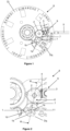
- a first embodiment of a clockwork movement 8 according to the invention is described below with reference to Figures 1 and 2
- the movement preferably includes a calendar corrector mechanism 9 provided to correct, for example, the date and day of the week indications.
- the correction mechanism may comprise a correction wheel set 1 acting as a driving wheel set capable of selectively engaging with two driven wheels to produce two separate unidirectional coupling devices.
- This correction wheel set is an integral part of a correction kinematic chain which is driven by the rotation of a control stem 5 of a conventional calendar movement when the latter is positioned in a predefined axial position, via a clutch device 7.
- the correction mobile 1 is pivoted on a clutch rocker 6 which is designed to combine the functions of coupling rocker, or horizontal clutch rocker, and also that of friction spring. More particularly, this rocker is shaped so as to pivot the mobile 1 while imparting to it a radial or substantially radial clamping force, which, due to a friction phenomenon, creates a braking or friction torque opposing the rotation of the correction mobile 1 relative to the rocker and thus drives this rocker in rotation.
- a clutch rocker 6 which is designed to combine the functions of coupling rocker, or horizontal clutch rocker, and also that of friction spring. More particularly, this rocker is shaped so as to pivot the mobile 1 while imparting to it a radial or substantially radial clamping force, which, due to a friction phenomenon, creates a braking or friction torque opposing the rotation of the correction mobile 1 relative to the rocker and thus drives this rocker in rotation.
- the lever 6 comprises at least a first element 61 for guiding the rotation of the first mobile 1, in particular the correction mobile 1, in particular the first shaft 11 of the first mobile 1, at least one friction element 62 intended to cooperate with an at least substantially cylindrical portion 10c of the first mobile, in particular the first shaft 11 of the first mobile, and at least one elastic element 63 intended to elastically return the at least one friction element into a state of cooperation with the portion of the first mobile, in particular in contact with the portion of the first mobile.
- the at least one friction element applies at least one radial or substantially radial force to the first shaft portion of the first mobile, in order to produce the braking or friction torque opposing the rotation of the correction wheel 1 relative to the rocker.
- the rotational guide element and the at least one friction element are merged.
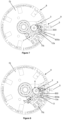
- the rocker 6 is provided with two elastic arms 6a, 6b which, once elastically deformed, are provided to receive the first shaft 11 of the correction wheel set 1 and define its pivot axis 1d.
- the arms preferably extend longitudinally to one end of the rocker.
- the arms are separated from each other by an opening 6d, in particular a slot-shaped opening, in particular a slot-shaped through opening.
- This opening 6d makes it possible to receive the first shaft 11.
- This opening preferably extends from the previously mentioned end.
- Each of the two elastic arms comprises at least one bearing surface 60a, 60b, 60c, 60d intended to cooperate with the cylindrical portion 10c of the shaft 11.
- each of the two elastic arms comprises at least one bearing surface 60a, 60b, 60c, 60d intended to cooperate punctually with the cylindrical portion 10c of the shaft 11 (i.e. according to a point of contact or according to a surface of limited area).
- the axis of rotation 1d of the mobile 1 is advantageously defined unequivocally by at least two bearing surfaces intended to cooperate punctually (i.e. according to a point of contact) with the cylindrical portion 10c of the shaft 11.
- the bearing surfaces are, for example, bosses made on the arms, but can also be confused with the arms.
- the bearing surfaces have, for example, a negative radius of curvature on the side of the opening 6d which is substantially distinct from the radius of curvature of the arms.
- the radii of curvature of the bearing surfaces can also be confused with the radii of curvature of the arms.
- the bearing surfaces may be rectilinear, i.e. they may have an infinite radius of curvature.
- the bearing surfaces may have a positive radius of curvature.
- the bearing surfaces of each of the arms are, for example, symmetrical to each other with respect to an axis of symmetry S of the opening 6d of the rocker 6.
- the elastic arms 6a, 6b are, for example, symmetrical to each other with respect to the axis of symmetry S of the opening 6d of the rocker 6. Preferably, this symmetry is maintained regardless of the degree of opening of the arms 6a, 6b.
- the axis of rotation 1d of the mobile 1 is defined unequivocally, regardless of the variations in diameter of the cylindrical portion 10c of the shaft 11, and therefore of the elastic deformation of the arms 6a, 6b.
- This definition is obtained by the geometry of the arms and the bearing surfaces that cooperate by contact on the cylindrical portion 10c. This definition is such that the axis 1d is positioned at the appropriate location allowing the correct operation of the gearing of the correction mobile 1 with the intermediate correction return mobile 2.
- the center distance between the mobiles 1 and 2 is determined independently of the variations in diameter of the cylindrical portion 10c of the shaft 11.
- the tightening torque of the cylindrical portion 10c is, for its part, controlled by the elastic properties and the pre-arming of the arms 6a and 6b.
- an opening 66, in particular a bore, formed on the rocker 6 is also provided so as to radially guide the rocker and pivot it around an axis of rotation 6f which coincides with that of the intermediate correction return 2.
- the rocker comprises a second element 66 for guiding the rocker in rotation around the second shaft 21.
- the rocker preferably does not include the first and second mobile, nor the first axis of the first mobile and the second axis of the second mobile.
- the component 65' can be embedded or fixed or mounted integrally with the rocker body 64'.
- the geometries of the arms 6a', 6b' are shaped so as to define the axis of rotation 1d' of the first mobile 1' while imparting an adequate tightening torque to its shaft 11' to obtain a desired friction torque.
- the pivoting of the rocker 6' in the plane is carried out by means of the rocker body 64' around an axis of rotation 6f'.
- This pivoting and this axis are defined by an opening 66', in particular a bore, made in the rocker body 64'.
- the axis thus defined coincides with that of the intermediate return wheel set 2' which is engaged with the driving wheel set 1'.
- an embodiment of a clutch device 7' comprises the rocker 6' as described previously, the first mobile 1' and the second mobile 2'.
- the first mobile is capable of coming directly into engagement with a third mobile of a first kinematic chain or possibly with a fourth mobile of a second kinematic chain depending on the state of the clutch, in particular depending on the position of the rocker.
- the first mobile in a first position of the rocker, is a driving mobile driving a first kinematic chain and, in a second position of the rocker, the first mobile is a driving mobile which can drive a second kinematic chain.
- the lever 6' may be provided with an arm, one side of which, in particular one end, is designed to be actuated by an additional control mechanism in order to disengage the wheel set 1' from the third wheel set or the fourth wheel set when the latter are capable of being actuated by a related adjustment device.
- the arm may also make it possible to immobilize the lever in another position, in particular a position in which the wheel set or wheels carried by the lever mesh with other elements.
- the resistive torque to the pivoting of the correction wheel set 1' which is produced by the friction elements 61', 62' is greater than 2, 3, or even 5, or even 6 times the resistive torque to the pivoting of the correction lever around the axis of rotation 6f'.
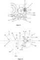
- a third embodiment of a 6" rocker is described below with reference to Figures 13 and 14 .
- This third embodiment differs from the second embodiment in that the rotational guide element of the first shaft 11" of the first mobile 1" is produced on the rocker body 64" and not on the component 65".
- the component comprises at least one friction element 62" and at least one elastic element 63".
- the friction elements and/or the elastic elements are only present on the component.
- a "" has been added to the numerical references designating the elements which are identical or which provide the same functions as in the first embodiment.
- the first mobile referenced "1" in the first embodiment is referenced "1" in the third embodiment.
- the axis of rotation 1d" of the driving mobile 1" is defined by the rocker body 64". Indeed, a bore 61" makes it possible to guide the shaft in rotation around the axis 1d".
- the fictional torque opposing the free rotation of the first mobile 1" is defined by the component 65". Indeed, as illustrated in Figures 13 and 14 , arms 6a", 6b" are pressed, at the level of bearing surfaces 60a" and 60b" which are merged with the arms 6a", 6b", on the portion 1c" of the shaft 11".
- the rotation of the rocker 6" in the plane is carried out by means of the rocker body 64" whose axis of rotation 6f" is defined by an opening 66", in particular a bore, made on the rocker body 64". This axis coincides with that of the return mobile 2" which is engaged with the driving mobile 1".
- an embodiment of a 7" clutch device comprises the rocker 6" as described previously, the first mobile 1" and the second mobile 2".
- the first mobile is capable of coming directly into engagement with a third mobile of a first kinematic chain or possibly with a fourth mobile of a second kinematic chain depending on the state of the clutch, in particular depending on the position of the rocker.
- the first mobile in a first position of the rocker, is a driving mobile driving a first kinematic chain and, in a second position of the rocker, the first mobile is a driving mobile capable of driving a second kinematic chain.
- the 6" rocker can be provided with an arm, one side of which, in particular one end, is designed to be actuated by an additional control mechanism in order to disengage the 1" mobile from the third mobile or the fourth mobile when the latter are capable of being actuated by a related adjustment device.
- the resistive torque to the pivoting of the correction wheel 1" which is produced by the friction elements 61", 62" is greater than 2, 3, or even 5, or even 6 times the resistive torque to the pivoting of the correction lever around the rotation axis 6f".
- the clutch device is arranged so that the rotation about its axis 1d, 1d', 1d", 6f, 6f', 6f" of the first mobile 1, 1', 1" and/or of the second mobile 2, 2', 2" involves the rotation of the rocker about its axis 6f, 6f', 6f" until the rocker or one of the first and second mobile comes into abutment against an element, in particular a mobile with which the first mobile or the second mobile meshes or a stop limiting the rotation or pivoting travel of the rocker.
- the resistive or resistant torque to the rotation of the first and/or the second mobile relative to the rocker in particular the sum of the resistive or resistant torques to the rotation of the first and the second mobile relative to the rocker, must be greater than the resistant or resistive torque of rotation or pivoting of the rocker relative to the movement frame.
- the torque resisting or resistive to the rotation of the first and/or second mobile relative to the rocker is 2 times greater, or even 3 times greater, or even 5 times greater, or even 6 times greater, than the resistive or resistant torque to the pivoting of the rocker around its axis of rotation or pivoting.
- the values of this torque must be brought back to the level of a common axis, for example the pivoting axis of the rocker.
- the at least one friction element cooperates with the first shaft alone, in particular with a cylindrical portion of the first shaft or, more generally, with a cylindrical portion of the first mobile.
- the at least one friction element may cooperate with the second shaft alone or, more generally, with a cylindrical portion of the second mobile, i.e. the mobile or the mobile shaft rotating around the axis around which the rocker pivots.
- a first friction element may be provided cooperating with the first mobile and a second friction element cooperating with the second mobile.
- the portion of the first mobile with which the friction element(s) cooperate is cylindrical and concentric with the mobile.
- this portion or surface may only be substantially cylindrical. In particular, it may be slightly frustoconical and/or have a slightly elliptical cross-section. Furthermore, the portion or surface may also be eccentric relative to the axis of rotation of the mobile.
- the invention also relates to a movement 8; 8';8" comprising a clutch device according to one of the embodiments described previously.
- the invention finally relates to a timepiece movement, in particular a watch, comprising such a movement.
- the invention has the advantage of providing a rocker of simple structure which is easy to mount in a movement and which also allows control of the friction torque applied to the clutch mobiles.
- a friction spring is manufactured in one piece with a clutch rocker.
- the spring can be provided to generate a radial force at the pivot axis of the drive wheel.
- the clutch device allows the rocker to rotate in a first direction when the second wheel is rotated in the first direction and allows the rocker to rotate in a second direction when the second wheel is rotated in the second direction.
- the at least one friction element preferably allows friction between the at least one friction element and the at least substantially cylindrical portion of the first mobile.
Landscapes
- Physics & Mathematics (AREA)
- General Physics & Mathematics (AREA)
- Engineering & Computer Science (AREA)
- General Engineering & Computer Science (AREA)
- Mechanical Engineering (AREA)
- Mechanical Operated Clutches (AREA)
- Gears, Cams (AREA)
- Manufacturing & Machinery (AREA)
- Metallurgy (AREA)
- Mechanical Control Devices (AREA)
- Electromechanical Clocks (AREA)
- Braking Arrangements (AREA)
Claims (19)
- Kupplungsvorrichtung (7; 7'; 7"), umfassend:- ein erstes Drehteil (1; 1'; 1"),- ein zweites Drehteil (2; 2'; 2"),- eine Wippe (6; 6'; 6"), die um eine erste Achse (6f; 6f'; 6f") drehbar gelagert ist und umfasst:o mindestens ein erstes Element (61; 61'; 61") zur Drehführung des ersten Drehteils (1; 1'; 1"),o mindestens ein Reibelement (62; 62'; 62"), das dazu bestimmt ist, mit einem mindestens im Wesentlichen zylindrischen Abschnitt (10c; 10c'; 10c") des ersten Drehteils (1; 1'; 1") zusammenzuwirken,o mindestens ein elastisches Element (63; 63'; 63"), das dazu bestimmt ist, das mindestens eine Reibelement (62; 62'; 62") elastisch in den Zustand des Zusammenwirkens mit dem mindestens im Wesentlichen zylindrischen Abschnitt (10c; 10c'; 10c") des ersten Drehteils (1; 1'; 1") zurückzuholen,o ein zweites Element (66; 66'; 66") zur Drehführung der Wippe um die erste Achse (6f; 6f'; 6f"),wobei das erste Führungselement (61; 61'; 61") Anlageflächen (60a, 60b, 60c und 60d) umfasst, die dazu bestimmt sind, durch Kontakt mit dem mindestens im Wesentlichen zylindrischen Abschnitt (10c; 10c'; 10c") zusammenzuwirken, wobei die Anlageflächen (60a, 60b, 60c und 60d):- einen unendlichen Krümmungsradius haben, oder- Erhebungen sind oder- dazu bestimmt sind, durch punktuellen Kontakt mit dem mindestens im Wesentlichen zylindrischen Abschnitt (10c; 10c'; 10c") des ersten Drehteils (1; 1'; 1") zusammenzuwirken,wobei die Wippe (6; 6'; 6") mit zwei elastischen Armen (6a, 6b; 6a', 6b'; 6a", 6b") ausgestattet ist, die jeweils mindestens eine der Anlageflächen (60a, 60b, 60c und 60d) aufweisen,wobei das erste Drehteil (1; 1'; 1") geeignet ist, je nach Zustand der Kupplung, insbesondere je nach Position der Wippe (6; 6'; 6"):- in eine erste Position zu gelangen, in der es direkt in Eingriff mit einem dritten Drehteil einer ersten kinematischen Kette steht, und- in eine zweite Position zu gelangen, in der es nicht in direktem Eingriff mit dem dritten Drehteil steht,
undwobei das erste Drehteil (1; 1'; 1") und das zweite Drehteil (2; 2'; 2") kinematisch verbunden, insbesondere durch Verzahnung kinematisch verbunden, im Besonderen durch direkte Verzahnung kinematisch verbunden sind,
undwobei die Kupplungsvorrichtung (7; 7'; 7") so ausgebildet ist, dass die Drehung des ersten Drehteils (1; 1'; 1") um seine Achse die Drehung der Wippe (6; 6'; 6") um die erste Achse (6f) bewirkt, bis die Wippe (6; 6'; 6") oder das erste Drehteil (1; 1'; 1") an ein Element anschlägt. - Vorrichtung nach dem vorhergehenden Anspruch, dadurch gekennzeichnet, dass das mindestens eine Reibelement (62; 62'; 62") mindestens eine radiale oder im Wesentlichen radiale Kraft auf den Abschnitt (10c; 10c'; 10c") des ersten Drehteils (1; 1'; 1") ausübt.
- Vorrichtung nach einem der vorhergehenden Ansprüche, dadurch gekennzeichnet, dass die Wippe (6; 6'; 6") eine Öffnung (6d; 6d'; 6d") zur Aufnahme des ersten Drehteils (1; 1'; 1") umfasst, insbesondere einen Schlitz (6d; 6d'; 6d").
- Kupplungsvorrichtung, umfassend:- ein erstes Drehteil,- ein zweites Drehteil,- eine Wippe, die um eine erste Achse drehbar gelagert ist und umfasst:o mindestens ein erstes Element zur Drehführung des zweiten Drehteils,o mindestens ein Reibelement, das dazu bestimmt ist, mit einem mindestens im Wesentlichen zylindrischen Abschnitt des zweiten Drehteils zusammenzuwirken,o mindestens ein elastisches Element, das dazu bestimmt ist, das mindestens eine Reibelement elastisch in den Zustand des Zusammenwirkens mit dem mindestens im Wesentlichen zylindrischen Abschnitt des zweiten Drehteils zurückzuholen,o ein zweites Element zur Drehführung der Wippe um die erste Achse,wobei das erste Führungselement Anlageflächen umfasst, die dazu bestimmt sind, durch Kontakt mit dem mindestens im Wesentlichen zylindrischen Abschnitt zusammenzuwirken, wobei die Anlageflächen:- einen unendlichen Krümmungsradius haben, oder- Erhebungen sind oder- dazu bestimmt sind, durch punktuellen Kontakt mit dem mindestens im Wesentlichen zylindrischen Abschnitt des zweiten Drehteils zusammenzuwirken,wobei die Wippe mit zwei elastischen Armen ausgestattet ist, die jeweils mindestens eine der Anlageflächen aufweisen,wobei das erste Drehteil geeignet ist, je nach Zustand der Kupplung, insbesondere je nach Position der Wippe:- in eine erste Position zu gelangen, in der es direkt in Eingriff mit einem dritten Drehteil einer ersten kinematischen Kette steht,
und- in eine zweite Position zu gelangen, in der es nicht in direktem Eingriff mit dem dritten Drehteil steht,
undwobei das erste Drehteil und das zweite Drehteil kinematisch verbunden, insbesondere durch Verzahnung kinematisch verbunden, im Besonderen durch direkte Verzahnung kinematisch verbunden sind,
undwobei die Kupplungsvorrichtung so ausgebildet ist, dass die Drehung des zweiten Drehteils um seine Achse die Drehung der Wippe um die erste Achse bewirkt, bis die Wippe oder das erste Drehteil an ein Element anschlägt. - Vorrichtung nach dem vorhergehenden Anspruch, dadurch gekennzeichnet, dass das mindestens eine Reibelement mindestens eine radiale oder im Wesentlichen radiale Kraft auf den Abschnitt des zweiten Drehteils ausübt.
- Vorrichtung nach einem der Ansprüche 4 bis 5, dadurch gekennzeichnet, dass die Wippe eine Öffnung zur Aufnahme des zweiten Drehteils umfasst, insbesondere einen Schlitz.
- Vorrichtung nach Anspruch 3 oder 6, dadurch gekennzeichnet, dass das mindestens eine Reibelement (62; 62'; 62") an einer Flanke oder an einem Flankenabschnitt des Schlitzes (6d; 6d'; 6d") angeordnet ist.
- Vorrichtung nach Anspruch 3, 6 oder 7, dadurch gekennzeichnet, dass das mindestens eine elastische Element (63; 63'; 63") einen Arm (6a, 6b) umfasst, von dem eine Flanke mindestens teilweise mit einem Flankenabschnitt des Schlitzes (6d; 6d'; 6d") deckungsgleich ist.
- Vorrichtung nach dem vorhergehenden Anspruch, dadurch gekennzeichnet, dass der Arm mindestens eine Anlagefläche (60a, 60b, 60c und 60d) des mindestens einen Reibelements (62; 62'; 62") umfasst.
- Vorrichtung nach einem der Ansprüche 8 und 9, dadurch gekennzeichnet, dass die Wippe (6; 6'; 6") zwei Arme umfasst, von denen Enden (60e, 60f) dazu ausgestaltet sind, den Eingriff der Welle zu ermöglichen, die beiden Enden (60e, 60f) insbesondere ein V bilden, welches das Eingreifen des ersten Drehteils (1; 1'; 1") beziehungsweise des zweiten Drehteils (2, 2', 2") ermöglicht, indem die Arme elastisch verformt werden.
- Vorrichtung nach einem der vorhergehenden Ansprüche, dadurch gekennzeichnet, dass das erste Führungselement (61; 61'; 61") und das mindestens eine Reibelement (62; 62'; 62") zusammenfallen.
- Vorrichtung nach einem der vorhergehenden Ansprüche, dadurch gekennzeichnet, dass die Wippe (6) einstückig ist.
- Vorrichtung nach einem der Ansprüche 1 bis 12, dadurch gekennzeichnet, dass die Wippe (6'; 6") einen Körper (64'; 64") und eine an den Körper (64'; 64") angesetzte Komponente (65'; 65") umfasst, wobei die Komponente das mindestens eine Reibelement (62; 62'; 62") und das mindestens eine elastische Element (63; 63'; 63") umfasst und/oder die Komponente das mindestens eine Element (61; 61'; 61") zur Drehführung umfasst.
- Kupplungsvorrichtung nach einem der vorhergehenden Ansprüche, dadurch gekennzeichnet, dass sie das Korrigieren einer Kalenderanzeige, einer Stundenanzeige oder einer von der Stunde abgeleiteten Anzeige ermöglicht oder das manuelle oder automatische Aufziehen eines Energiespeichers ermöglicht.
- Kupplungsvorrichtung nach einem der vorhergehenden Ansprüche, dadurch gekennzeichnet, dass das erste Drehteil (1; 1'; 1") geeignet ist, je nach Zustand der Kupplung, insbesondere je nach Position der Wippe (6; 6'; 6") :- in eine erste Position zu gelangen, in der es direkt in Eingriff mit dem dritten Drehteil steht, oder- in eine zweite Position zu gelangen, in der es direkt in Eingriff mit einem vierten Drehteil einer zweiten kinematischen Kette steht.
- Uhrwerk (8), das eine Kupplungsvorrichtung (7; 7'; 7") nach einem der vorhergehenden Ansprüche umfasst.
- Zeitmessgerät, insbesondere Uhr, umfassend ein Uhrwerk nach dem vorhergehenden Anspruch oder eine Kupplungsvorrichtung nach einem der Ansprüche 1 bis 15.
- Verwendung, als Komponente einer Kupplungsvorrichtung nach einem der Ansprüche 1, 2, 3 und 7 bis 15, einer Wippe (6; 6'; 6"), umfassend:- mindestens ein erstes Element (61; 61'; 61") zur Drehführung des ersten Drehteils (1; 1'; 1"),- mindestens ein Reibelement (62; 62'; 62"), das dazu bestimmt ist, mit einem mindestens im Wesentlichen zylindrischen Abschnitt (10c; 10c'; 10c") des ersten Drehteils (1; 1'; 1") zusammenzuwirken, und- mindestens ein elastisches Element (63; 63'; 63"), das dazu bestimmt ist, das mindestens eine Reibelement elastisch in den Zustand des Zusammenwirkens mit dem Abschnitt des ersten Drehteils (1; 1'; 1"), insbesondere in den Kontakt mit dem Abschnitt des ersten Drehteils (1; 1'; 1"), zurückzuholen.
- Verwendung, als Komponente einer Kupplungsvorrichtung nach einem der Ansprüche 4 bis 15, einer Wippe, umfassend:- mindestens ein erstes Element zur Drehführung des zweiten Drehteils,- mindestens ein Reibelement, das dazu bestimmt ist, mit einem mindestens im Wesentlichen zylindrischen Abschnitt des zweiten Drehteils zusammenzuwirken, und- mindestens ein elastisches Element, das dazu bestimmt ist, das mindestens eine Reibelement elastisch in den Zustand des Zusammenwirkens mit dem Abschnitt des zweiten Drehteils, insbesondere in den Kontakt mit dem Abschnitt des zweiten Drehteils, zurückzuholen.
Priority Applications (2)
| Application Number | Priority Date | Filing Date | Title |
|---|---|---|---|
| EP19153581.4A EP3499319B1 (de) | 2012-08-21 | 2013-08-20 | Kupplungswippe und kupplungsvorrichtung für uhrmechanismus |
| EP13181020.2A EP2701014B1 (de) | 2012-08-21 | 2013-08-20 | Kupplungsvorrichtung für Uhrmechanismus |
Applications Claiming Priority (2)
| Application Number | Priority Date | Filing Date | Title |
|---|---|---|---|
| EP12181256 | 2012-08-21 | ||
| EP13181020.2A EP2701014B1 (de) | 2012-08-21 | 2013-08-20 | Kupplungsvorrichtung für Uhrmechanismus |
Related Child Applications (2)
| Application Number | Title | Priority Date | Filing Date |
|---|---|---|---|
| EP19153581.4A Division EP3499319B1 (de) | 2012-08-21 | 2013-08-20 | Kupplungswippe und kupplungsvorrichtung für uhrmechanismus |
| EP19153581.4A Division-Into EP3499319B1 (de) | 2012-08-21 | 2013-08-20 | Kupplungswippe und kupplungsvorrichtung für uhrmechanismus |
Publications (2)
| Publication Number | Publication Date |
|---|---|
| EP2701014A1 EP2701014A1 (de) | 2014-02-26 |
| EP2701014B1 true EP2701014B1 (de) | 2025-07-09 |
Family
ID=48985688
Family Applications (2)
| Application Number | Title | Priority Date | Filing Date |
|---|---|---|---|
| EP13181020.2A Active EP2701014B1 (de) | 2012-08-21 | 2013-08-20 | Kupplungsvorrichtung für Uhrmechanismus |
| EP19153581.4A Active EP3499319B1 (de) | 2012-08-21 | 2013-08-20 | Kupplungswippe und kupplungsvorrichtung für uhrmechanismus |
Family Applications After (1)
| Application Number | Title | Priority Date | Filing Date |
|---|---|---|---|
| EP19153581.4A Active EP3499319B1 (de) | 2012-08-21 | 2013-08-20 | Kupplungswippe und kupplungsvorrichtung für uhrmechanismus |
Country Status (4)
| Country | Link |
|---|---|
| US (1) | US9164482B2 (de) |
| EP (2) | EP2701014B1 (de) |
| JP (2) | JP6334111B2 (de) |
| CN (1) | CN103698995B (de) |
Families Citing this family (22)
| Publication number | Priority date | Publication date | Assignee | Title |
|---|---|---|---|---|
| CN104081083B (zh) * | 2012-02-22 | 2017-05-24 | 三菱重工压缩机有限公司 | 回转装置以及旋转机械 |
| EP2914877B1 (de) * | 2012-10-31 | 2021-02-03 | Parker-Hannifin Corporation | Getriebesteuerungssystem zur vibrationsdämpfung |
| EP2945026B1 (de) | 2014-05-14 | 2018-01-03 | ETA SA Manufacture Horlogère Suisse | Schnellkorrekturmechanismus für Uhr |
| EP2945024B1 (de) | 2014-05-14 | 2017-07-12 | ETA SA Manufacture Horlogère Suisse | Sperrwippe für Uhr |
| EP3026506B1 (de) * | 2014-11-26 | 2019-01-16 | The Swatch Group Management Services AG | Zeitmessgerät mit Geschwindigkeitswahlschalter |
| JP6450179B2 (ja) * | 2014-12-16 | 2019-01-09 | セイコーインスツル株式会社 | 巻上機構、ムーブメントおよび時計 |
| JP6492928B2 (ja) * | 2015-04-22 | 2019-04-03 | セイコーエプソン株式会社 | 時計および時計の製造方法 |
| CH711049A1 (de) * | 2015-05-08 | 2016-11-15 | Bucherer Ag | Jahreskalender für mechanische Uhren. |
| EP3376309B1 (de) * | 2017-03-17 | 2022-05-18 | Montres Jaquet Droz SA | Aufziehmechanismus einer uhr |
| CH713604A1 (fr) * | 2017-03-22 | 2018-09-28 | Sa De La Manufacture Dhorlogerie Audemars Piguet & Cie | Mécanisme de sélection et d'actionnement ainsi que dispositif de réglage de fonctions d'une pièce d'horlogerie. |
| EP3382472B1 (de) * | 2017-03-30 | 2025-08-20 | Rolex Sa | Führungslager einer unruhwelle einer uhr |
| EP3396470B1 (de) * | 2017-04-24 | 2020-01-01 | ETA SA Manufacture Horlogère Suisse | Mechanische bremsvorrichtung für drehteil einer uhr |
| CH714795A9 (fr) * | 2018-03-16 | 2020-01-15 | Lvmh Swiss Mft Sa | Pièce d'horlogerie comprenant un mécanisme de correction des indications fournies par un premier et deuxième organe d'affichage. |
| CH714826B1 (fr) * | 2018-03-21 | 2022-11-30 | Bulgari Horlogerie Sa | Système horloger de transmission. |
| EP3547043B1 (de) * | 2018-03-26 | 2021-02-17 | Montres Breguet S.A. | Korrekturmechanismus der uhranzeige |
| EP3608729B1 (de) | 2018-08-09 | 2024-07-31 | Rolex Sa | Kalendervorrichtung für uhr |
| CH716553B1 (fr) * | 2019-08-30 | 2023-03-15 | Lvmh Swiss Mft Sa Zenith Succursale De Lvmh Swiss Mft Sa | Mécanisme horloger de génération d'une friction limitant le couple transmis entre deux pièces rotatitves et ressort de friction pour un tel mécanisme. |
| EP3923084B1 (de) * | 2020-06-12 | 2024-07-24 | ETA SA Manufacture Horlogère Suisse | Antikorrektursystem einer anzeige für eine uhr |
| JP7811839B2 (ja) * | 2020-12-22 | 2026-02-06 | ロレックス・ソシエテ・アノニム | ノッチシステム用ばね及び時計ノッチシステム |
| JP7811838B2 (ja) * | 2020-12-22 | 2026-02-06 | ロレックス・ソシエテ・アノニム | ノッチシステム用ばね及び時計ノッチシステム |
| JP2024514353A (ja) * | 2021-04-21 | 2024-04-01 | パテック フィリップ ソシエテ アノニム ジュネーブ | 時計機構又は時計を備えることを意図し且つ少なくとも1つの弾性要素及び少なくとも1つの第1及び第2時計コンポーネントを含む組立体 |
| EP4546056A1 (de) * | 2023-10-24 | 2025-04-30 | ETA SA Manufacture Horlogère Suisse | Uhrwerk, das einen mechanismus zur einstellung der position von anzeigen umfasst |
Citations (1)
| Publication number | Priority date | Publication date | Assignee | Title |
|---|---|---|---|---|
| JPS54118860U (de) * | 1978-02-09 | 1979-08-20 |
Family Cites Families (32)
| Publication number | Priority date | Publication date | Assignee | Title |
|---|---|---|---|---|
| US325536A (en) * | 1885-09-01 | Stem-winding attachment for watches | ||
| US1054447A (en) * | 1911-11-07 | 1913-02-25 | New Haven Clock Co | Stem-winding and stem-setting watch. |
| CH302210A (fr) | 1952-05-29 | 1954-10-15 | Schild Sa A | Dispositif d'entraînement d'une aiguille de seconde indépendante. |
| GB870989A (en) | 1956-10-08 | 1961-06-21 | Junghans Geb Ag | Improvements in or relating to a frictional retaining device for the alarm setting shaft of a timepiece |
| US3470687A (en) * | 1966-12-15 | 1969-10-07 | Suwa Seikosha Kk | Date and day correcting device of a calendar timepiece |
| JPS4945973Y1 (de) * | 1970-12-03 | 1974-12-16 | ||
| JPS5214462Y2 (de) * | 1971-07-08 | 1977-04-01 | ||
| CH1102972A4 (de) * | 1972-07-24 | 1975-08-15 | ||
| JPS5111664B2 (de) * | 1972-09-08 | 1976-04-13 | ||
| CH427673A4 (de) * | 1973-03-23 | 1975-06-30 | ||
| CH1190373A4 (de) * | 1973-08-17 | 1976-12-31 | ||
| US3837161A (en) * | 1973-12-26 | 1974-09-24 | Timex Corp | Universal time watch |
| CH490874A4 (de) * | 1974-04-08 | 1977-03-15 | ||
| US3874162A (en) * | 1974-07-22 | 1975-04-01 | Timex Corp | Solid state watch stem detent and switch assembly |
| CH1468974A4 (de) * | 1974-11-01 | 1976-04-30 | ||
| JPS5555426Y2 (de) * | 1975-11-05 | 1980-12-22 | ||
| JPS52156664A (en) * | 1976-06-21 | 1977-12-27 | Seiko Epson Corp | Calendar correcting mechanism |
| JPS5263067A (en) * | 1976-10-29 | 1977-05-25 | Nippon Telegr & Teleph Corp <Ntt> | Production of semiconductor device |
| JPS54170870U (de) | 1978-05-22 | 1979-12-03 | ||
| JPS5658475A (en) * | 1979-10-17 | 1981-05-21 | Shigemi Imamura | Device for stacking and conveying bundles of laver sheets |
| DE2952341C2 (de) * | 1979-12-24 | 1982-11-25 | Pforzheimer Uhren-Rohwerke Porta Gmbh & Co, 7530 Pforzheim | Stellmechanismus für eine Uhr |
| JPS5653343Y2 (de) * | 1980-06-18 | 1981-12-11 | ||
| US4464062A (en) * | 1981-07-10 | 1984-08-07 | Kuniyoshi Inage | Battery powered time piece |
| DE69826386T2 (de) * | 1997-01-17 | 2005-02-17 | Seiko Epson Corp. | Anzeigevorrichtung und zeitmessgerät mit derselben |
| EP1152303B1 (de) * | 2000-05-05 | 2006-07-19 | Rolex Sa | Uhr mit Aufzugsmechanismus und mit Korrekturmechanismus für mindestens zwei anzeigende Organe |
| EP1862871B1 (de) * | 2006-05-31 | 2008-05-21 | Montres Breguet S.A. | Uhr, die eine verbesserte Vorrichtung zur Zeiteinstellung umfasst |
| CH699831B1 (fr) | 2006-11-06 | 2010-05-14 | Eta Sa Mft Horlogere Suisse | Dispositif de correction d'un mécanisme d'affichage pour pièce d'horlogerie. |
| DE602006013838D1 (de) * | 2006-11-06 | 2010-06-02 | Longines Montres Comp D | Uhr, die einen Korrekturmechanismus für eine Vorrichtung zur Anzeige einer Zeitgröße umfasst |
| DE602007006151D1 (de) * | 2007-02-14 | 2010-06-10 | Maurice Lacroix Sa | Mechanismus zur umschaltbaren Übertragung |
| EP2012199B9 (de) | 2007-07-02 | 2019-02-13 | Rolex Sa | Uhr, die mit einer Vorrichtung zur Steuerung von Funktionen und/oder Stundenanzeigen ausgerüstet ist |
| CH703697B1 (fr) | 2010-09-02 | 2015-06-15 | Manuf La Joux Perret Sa | Dispositif de correction et mouvement horloger comprenant ce dispositif de correction |
| EP2453322B1 (de) * | 2010-11-16 | 2013-07-17 | Omega SA | Schneller Korrektor einer Zeitgrößenanzeige für Uhr |
-
2013
- 2013-08-20 EP EP13181020.2A patent/EP2701014B1/de active Active
- 2013-08-20 US US13/971,517 patent/US9164482B2/en active Active
- 2013-08-20 EP EP19153581.4A patent/EP3499319B1/de active Active
- 2013-08-20 JP JP2013170031A patent/JP6334111B2/ja active Active
- 2013-08-21 CN CN201310367549.XA patent/CN103698995B/zh active Active
-
2018
- 2018-04-26 JP JP2018085013A patent/JP6797859B2/ja active Active
Patent Citations (1)
| Publication number | Priority date | Publication date | Assignee | Title |
|---|---|---|---|---|
| JPS54118860U (de) * | 1978-02-09 | 1979-08-20 |
Also Published As
| Publication number | Publication date |
|---|---|
| JP2018136339A (ja) | 2018-08-30 |
| EP3499319A3 (de) | 2019-07-17 |
| CN103698995A (zh) | 2014-04-02 |
| EP3499319B1 (de) | 2025-01-15 |
| JP6797859B2 (ja) | 2020-12-09 |
| JP6334111B2 (ja) | 2018-05-30 |
| EP3499319A2 (de) | 2019-06-19 |
| JP2014041124A (ja) | 2014-03-06 |
| US9164482B2 (en) | 2015-10-20 |
| EP2701014A1 (de) | 2014-02-26 |
| CN103698995B (zh) | 2017-03-01 |
| US20140056112A1 (en) | 2014-02-27 |
Similar Documents
| Publication | Publication Date | Title |
|---|---|---|
| EP2701014B1 (de) | Kupplungsvorrichtung für Uhrmechanismus | |
| EP2533110B1 (de) | Uhr, die mit einer Vorrichtung zur Einstellung von Funktionen und/oder Stundenanzeigen ausgerüstet ist | |
| EP2115537B1 (de) | Zeitmessgerät mit einem mechanismus zum betrieb einer vorrichtung zur anzeige eines zeitbezogenen wertes | |
| EP2724199B1 (de) | Uhr mit einem aufzugsmechanismus und mindestens einem mechanismus zur korrektur von wenigstens einem indikatorelement | |
| EP1152303B1 (de) | Uhr mit Aufzugsmechanismus und mit Korrekturmechanismus für mindestens zwei anzeigende Organe | |
| EP2945026B1 (de) | Schnellkorrekturmechanismus für Uhr | |
| EP3602202B1 (de) | Vorrichtung zur einstellung von funktionen einer uhr | |
| EP3483663A1 (de) | Antriebsvorrichtung für kalendersystem einer uhr | |
| EP3032354B1 (de) | Befestigungssystem einer spiralfeder | |
| EP2957964B1 (de) | Kippkupplung für uhren | |
| EP2798413B1 (de) | Feder für uhrwerk | |
| EP3489766B1 (de) | Mechanismus zur korrektur einer bewegungsfunktion einer uhr | |
| EP2798414B1 (de) | Feder für uhrwerk | |
| EP4053639B1 (de) | Vorrichtung zur auswahl von uhrfunktionen | |
| EP0479147B1 (de) | Mechanische und/oder elektromechanische Uhr | |
| EP4053640B1 (de) | Vorrichtung zur auswahl von uhrfunktionen | |
| EP3955065B1 (de) | Indexierungsvorrichtung einer zugstange | |
| EP0129683A1 (de) | Datumschaltwerk für Uhren | |
| EP1558972B1 (de) | Vorrichtung zur kupplung eines zahnrades | |
| EP4053645A1 (de) | Vorrichtung zur auswahl von uhrfunktionen | |
| EP4414792A1 (de) | Korrekturmechanismus für mindestens eine erste und zweite anzeigevorrichtung einer uhr | |
| CH717111B1 (fr) | Mécanisme de correction d'affichage et mouvement horloger comportant ce mécanisme. | |
| EP3839662A1 (de) | Zeiteinstellungsmechanismus einer uhr, der ein zeiteinstellungssystem mit versetzten stangen umfasst | |
| CH720984B1 (fr) | Mécanisme de commande pour pièce d'horlogerie | |
| CH714615A2 (fr) | Mécanisme de transmission d'une force d'armage, mouvement et pièce d'horlogerie mécanique. |
Legal Events
| Date | Code | Title | Description |
|---|---|---|---|
| PUAI | Public reference made under article 153(3) epc to a published international application that has entered the european phase |
Free format text: ORIGINAL CODE: 0009012 |
|
| AK | Designated contracting states |
Kind code of ref document: A1 Designated state(s): AL AT BE BG CH CY CZ DE DK EE ES FI FR GB GR HR HU IE IS IT LI LT LU LV MC MK MT NL NO PL PT RO RS SE SI SK SM TR |
|
| AX | Request for extension of the european patent |
Extension state: BA ME |
|
| 17P | Request for examination filed |
Effective date: 20140826 |
|
| RBV | Designated contracting states (corrected) |
Designated state(s): AL AT BE BG CH CY CZ DE DK EE ES FI FR GB GR HR HU IE IS IT LI LT LU LV MC MK MT NL NO PL PT RO RS SE SI SK SM TR |
|
| STAA | Information on the status of an ep patent application or granted ep patent |
Free format text: STATUS: EXAMINATION IS IN PROGRESS |
|
| 17Q | First examination report despatched |
Effective date: 20181218 |
|
| TPAC | Observations filed by third parties |
Free format text: ORIGINAL CODE: EPIDOSNTIPA |
|
| TPAC | Observations filed by third parties |
Free format text: ORIGINAL CODE: EPIDOSNTIPA |
|
| TPAC | Observations filed by third parties |
Free format text: ORIGINAL CODE: EPIDOSNTIPA |
|
| TPAC | Observations filed by third parties |
Free format text: ORIGINAL CODE: EPIDOSNTIPA |
|
| P01 | Opt-out of the competence of the unified patent court (upc) registered |
Effective date: 20230530 |
|
| REG | Reference to a national code |
Ref country code: DE Ref legal event code: R079 Free format text: PREVIOUS MAIN CLASS: G04B0019250000 Ipc: G04B0013020000 Ref country code: DE Ref legal event code: R079 Ref document number: 602013086880 Country of ref document: DE Free format text: PREVIOUS MAIN CLASS: G04B0019250000 Ipc: G04B0013020000 |
|
| GRAP | Despatch of communication of intention to grant a patent |
Free format text: ORIGINAL CODE: EPIDOSNIGR1 |
|
| STAA | Information on the status of an ep patent application or granted ep patent |
Free format text: STATUS: GRANT OF PATENT IS INTENDED |
|
| RIC1 | Information provided on ipc code assigned before grant |
Ipc: G04B 19/25 20060101ALI20250113BHEP Ipc: G04B 27/06 20060101ALI20250113BHEP Ipc: G04B 11/00 20060101ALI20250113BHEP Ipc: G04B 13/02 20060101AFI20250113BHEP |
|
| INTG | Intention to grant announced |
Effective date: 20250131 |
|
| GRAS | Grant fee paid |
Free format text: ORIGINAL CODE: EPIDOSNIGR3 |
|
| GRAA | (expected) grant |
Free format text: ORIGINAL CODE: 0009210 |
|
| STAA | Information on the status of an ep patent application or granted ep patent |
Free format text: STATUS: THE PATENT HAS BEEN GRANTED |
|
| AK | Designated contracting states |
Kind code of ref document: B1 Designated state(s): AL AT BE BG CH CY CZ DE DK EE ES FI FR GB GR HR HU IE IS IT LI LT LU LV MC MK MT NL NO PL PT RO RS SE SI SK SM TR |
|
| REG | Reference to a national code |
Ref country code: GB Ref legal event code: FG4D Free format text: NOT ENGLISH |
|
| REG | Reference to a national code |
Ref country code: CH Ref legal event code: EP |
|
| REG | Reference to a national code |
Ref country code: IE Ref legal event code: FG4D Free format text: LANGUAGE OF EP DOCUMENT: FRENCH |
|
| REG | Reference to a national code |
Ref country code: DE Ref legal event code: R096 Ref document number: 602013086880 Country of ref document: DE |
|
| PGFP | Annual fee paid to national office [announced via postgrant information from national office to epo] |
Ref country code: DE Payment date: 20250812 Year of fee payment: 13 |
|
| PGFP | Annual fee paid to national office [announced via postgrant information from national office to epo] |
Ref country code: GB Payment date: 20250826 Year of fee payment: 13 |
|
| PGFP | Annual fee paid to national office [announced via postgrant information from national office to epo] |
Ref country code: FR Payment date: 20250828 Year of fee payment: 13 |
|
| PGFP | Annual fee paid to national office [announced via postgrant information from national office to epo] |
Ref country code: CH Payment date: 20250901 Year of fee payment: 13 |
|
| REG | Reference to a national code |
Ref country code: NL Ref legal event code: MP Effective date: 20250709 |
|
| PG25 | Lapsed in a contracting state [announced via postgrant information from national office to epo] |
Ref country code: PT Free format text: LAPSE BECAUSE OF FAILURE TO SUBMIT A TRANSLATION OF THE DESCRIPTION OR TO PAY THE FEE WITHIN THE PRESCRIBED TIME-LIMIT Effective date: 20251110 |
|
| PG25 | Lapsed in a contracting state [announced via postgrant information from national office to epo] |
Ref country code: NL Free format text: LAPSE BECAUSE OF FAILURE TO SUBMIT A TRANSLATION OF THE DESCRIPTION OR TO PAY THE FEE WITHIN THE PRESCRIBED TIME-LIMIT Effective date: 20250709 |
|
| REG | Reference to a national code |
Ref country code: AT Ref legal event code: MK05 Ref document number: 1812380 Country of ref document: AT Kind code of ref document: T Effective date: 20250709 |
|
| PG25 | Lapsed in a contracting state [announced via postgrant information from national office to epo] |
Ref country code: IS Free format text: LAPSE BECAUSE OF FAILURE TO SUBMIT A TRANSLATION OF THE DESCRIPTION OR TO PAY THE FEE WITHIN THE PRESCRIBED TIME-LIMIT Effective date: 20251109 |
|
| PG25 | Lapsed in a contracting state [announced via postgrant information from national office to epo] |
Ref country code: NO Free format text: LAPSE BECAUSE OF FAILURE TO SUBMIT A TRANSLATION OF THE DESCRIPTION OR TO PAY THE FEE WITHIN THE PRESCRIBED TIME-LIMIT Effective date: 20251009 |
|
| REG | Reference to a national code |
Ref country code: LT Ref legal event code: MG9D |
|
| PG25 | Lapsed in a contracting state [announced via postgrant information from national office to epo] |
Ref country code: AT Free format text: LAPSE BECAUSE OF FAILURE TO SUBMIT A TRANSLATION OF THE DESCRIPTION OR TO PAY THE FEE WITHIN THE PRESCRIBED TIME-LIMIT Effective date: 20250709 |
|
| PG25 | Lapsed in a contracting state [announced via postgrant information from national office to epo] |
Ref country code: FI Free format text: LAPSE BECAUSE OF FAILURE TO SUBMIT A TRANSLATION OF THE DESCRIPTION OR TO PAY THE FEE WITHIN THE PRESCRIBED TIME-LIMIT Effective date: 20250709 |
|
| PG25 | Lapsed in a contracting state [announced via postgrant information from national office to epo] |
Ref country code: HR Free format text: LAPSE BECAUSE OF FAILURE TO SUBMIT A TRANSLATION OF THE DESCRIPTION OR TO PAY THE FEE WITHIN THE PRESCRIBED TIME-LIMIT Effective date: 20250709 |
|
| PG25 | Lapsed in a contracting state [announced via postgrant information from national office to epo] |
Ref country code: GR Free format text: LAPSE BECAUSE OF FAILURE TO SUBMIT A TRANSLATION OF THE DESCRIPTION OR TO PAY THE FEE WITHIN THE PRESCRIBED TIME-LIMIT Effective date: 20251010 |
|
| PG25 | Lapsed in a contracting state [announced via postgrant information from national office to epo] |
Ref country code: SE Free format text: LAPSE BECAUSE OF FAILURE TO SUBMIT A TRANSLATION OF THE DESCRIPTION OR TO PAY THE FEE WITHIN THE PRESCRIBED TIME-LIMIT Effective date: 20250709 |
|
| PG25 | Lapsed in a contracting state [announced via postgrant information from national office to epo] |
Ref country code: LV Free format text: LAPSE BECAUSE OF FAILURE TO SUBMIT A TRANSLATION OF THE DESCRIPTION OR TO PAY THE FEE WITHIN THE PRESCRIBED TIME-LIMIT Effective date: 20250709 |
|
| PG25 | Lapsed in a contracting state [announced via postgrant information from national office to epo] |
Ref country code: BG Free format text: LAPSE BECAUSE OF FAILURE TO SUBMIT A TRANSLATION OF THE DESCRIPTION OR TO PAY THE FEE WITHIN THE PRESCRIBED TIME-LIMIT Effective date: 20250709 Ref country code: PL Free format text: LAPSE BECAUSE OF FAILURE TO SUBMIT A TRANSLATION OF THE DESCRIPTION OR TO PAY THE FEE WITHIN THE PRESCRIBED TIME-LIMIT Effective date: 20250709 |
|
| PG25 | Lapsed in a contracting state [announced via postgrant information from national office to epo] |
Ref country code: RS Free format text: LAPSE BECAUSE OF FAILURE TO SUBMIT A TRANSLATION OF THE DESCRIPTION OR TO PAY THE FEE WITHIN THE PRESCRIBED TIME-LIMIT Effective date: 20251009 |
|
| PG25 | Lapsed in a contracting state [announced via postgrant information from national office to epo] |
Ref country code: ES Free format text: LAPSE BECAUSE OF FAILURE TO SUBMIT A TRANSLATION OF THE DESCRIPTION OR TO PAY THE FEE WITHIN THE PRESCRIBED TIME-LIMIT Effective date: 20250709 |
|
| PG25 | Lapsed in a contracting state [announced via postgrant information from national office to epo] |
Ref country code: RO Free format text: LAPSE BECAUSE OF FAILURE TO SUBMIT A TRANSLATION OF THE DESCRIPTION OR TO PAY THE FEE WITHIN THE PRESCRIBED TIME-LIMIT Effective date: 20250709 |
|
| PG25 | Lapsed in a contracting state [announced via postgrant information from national office to epo] |
Ref country code: SM Free format text: LAPSE BECAUSE OF FAILURE TO SUBMIT A TRANSLATION OF THE DESCRIPTION OR TO PAY THE FEE WITHIN THE PRESCRIBED TIME-LIMIT Effective date: 20250709 |
|
| PG25 | Lapsed in a contracting state [announced via postgrant information from national office to epo] |
Ref country code: DK Free format text: LAPSE BECAUSE OF FAILURE TO SUBMIT A TRANSLATION OF THE DESCRIPTION OR TO PAY THE FEE WITHIN THE PRESCRIBED TIME-LIMIT Effective date: 20250709 |
|
| PG25 | Lapsed in a contracting state [announced via postgrant information from national office to epo] |
Ref country code: LU Free format text: LAPSE BECAUSE OF NON-PAYMENT OF DUE FEES Effective date: 20250820 Ref country code: IT Free format text: LAPSE BECAUSE OF FAILURE TO SUBMIT A TRANSLATION OF THE DESCRIPTION OR TO PAY THE FEE WITHIN THE PRESCRIBED TIME-LIMIT Effective date: 20250709 |