EP2700483B1 - Bilderzeugungsvorrichtung und Schneidegerät - Google Patents
Bilderzeugungsvorrichtung und Schneidegerät Download PDFInfo
- Publication number
- EP2700483B1 EP2700483B1 EP13172332.2A EP13172332A EP2700483B1 EP 2700483 B1 EP2700483 B1 EP 2700483B1 EP 13172332 A EP13172332 A EP 13172332A EP 2700483 B1 EP2700483 B1 EP 2700483B1
- Authority
- EP
- European Patent Office
- Prior art keywords
- continuous sheet
- image
- cutting
- image forming
- cut
- Prior art date
- Legal status (The legal status is an assumption and is not a legal conclusion. Google has not performed a legal analysis and makes no representation as to the accuracy of the status listed.)
- Active
Links
Images


Classifications
-
- B—PERFORMING OPERATIONS; TRANSPORTING
- B26—HAND CUTTING TOOLS; CUTTING; SEVERING
- B26D—CUTTING; DETAILS COMMON TO MACHINES FOR PERFORATING, PUNCHING, CUTTING-OUT, STAMPING-OUT OR SEVERING
- B26D5/00—Arrangements for operating and controlling machines or devices for cutting, cutting-out, stamping-out, punching, perforating, or severing by means other than cutting
- B26D5/20—Arrangements for operating and controlling machines or devices for cutting, cutting-out, stamping-out, punching, perforating, or severing by means other than cutting with interrelated action between the cutting member and work feed
- B26D5/30—Arrangements for operating and controlling machines or devices for cutting, cutting-out, stamping-out, punching, perforating, or severing by means other than cutting with interrelated action between the cutting member and work feed having the cutting member controlled by scanning a record carrier
- B26D5/34—Arrangements for operating and controlling machines or devices for cutting, cutting-out, stamping-out, punching, perforating, or severing by means other than cutting with interrelated action between the cutting member and work feed having the cutting member controlled by scanning a record carrier scanning being effected by a photosensitive device
-
- B—PERFORMING OPERATIONS; TRANSPORTING
- B26—HAND CUTTING TOOLS; CUTTING; SEVERING
- B26D—CUTTING; DETAILS COMMON TO MACHINES FOR PERFORATING, PUNCHING, CUTTING-OUT, STAMPING-OUT OR SEVERING
- B26D1/00—Cutting through work characterised by the nature or movement of the cutting member or particular materials not otherwise provided for; Apparatus or machines therefor; Cutting members therefor
- B26D1/01—Cutting through work characterised by the nature or movement of the cutting member or particular materials not otherwise provided for; Apparatus or machines therefor; Cutting members therefor involving a cutting member which does not travel with the work
- B26D1/04—Cutting through work characterised by the nature or movement of the cutting member or particular materials not otherwise provided for; Apparatus or machines therefor; Cutting members therefor involving a cutting member which does not travel with the work having a linearly-movable cutting member
- B26D1/06—Cutting through work characterised by the nature or movement of the cutting member or particular materials not otherwise provided for; Apparatus or machines therefor; Cutting members therefor involving a cutting member which does not travel with the work having a linearly-movable cutting member wherein the cutting member reciprocates
- B26D1/08—Cutting through work characterised by the nature or movement of the cutting member or particular materials not otherwise provided for; Apparatus or machines therefor; Cutting members therefor involving a cutting member which does not travel with the work having a linearly-movable cutting member wherein the cutting member reciprocates of the guillotine type
- B26D1/09—Cutting through work characterised by the nature or movement of the cutting member or particular materials not otherwise provided for; Apparatus or machines therefor; Cutting members therefor involving a cutting member which does not travel with the work having a linearly-movable cutting member wherein the cutting member reciprocates of the guillotine type with a plurality of cutting members
- B26D1/095—Cutting through work characterised by the nature or movement of the cutting member or particular materials not otherwise provided for; Apparatus or machines therefor; Cutting members therefor involving a cutting member which does not travel with the work having a linearly-movable cutting member wherein the cutting member reciprocates of the guillotine type with a plurality of cutting members for thin material, e.g. for sheets, strips or the like
-
- B—PERFORMING OPERATIONS; TRANSPORTING
- B41—PRINTING; LINING MACHINES; TYPEWRITERS; STAMPS
- B41J—TYPEWRITERS; SELECTIVE PRINTING MECHANISMS, i.e. MECHANISMS PRINTING OTHERWISE THAN FROM A FORME; CORRECTION OF TYPOGRAPHICAL ERRORS
- B41J11/00—Devices or arrangements of selective printing mechanisms, e.g. ink-jet printers or thermal printers, for supporting or handling copy material in sheet or web form
- B41J11/66—Applications of cutting devices
- B41J11/663—Controlling cutting, cutting resulting in special shapes of the cutting line, e.g. controlling cutting positions, e.g. for cutting in the immediate vicinity of a printed image
-
- B—PERFORMING OPERATIONS; TRANSPORTING
- B41—PRINTING; LINING MACHINES; TYPEWRITERS; STAMPS
- B41J—TYPEWRITERS; SELECTIVE PRINTING MECHANISMS, i.e. MECHANISMS PRINTING OTHERWISE THAN FROM A FORME; CORRECTION OF TYPOGRAPHICAL ERRORS
- B41J11/00—Devices or arrangements of selective printing mechanisms, e.g. ink-jet printers or thermal printers, for supporting or handling copy material in sheet or web form
- B41J11/66—Applications of cutting devices
- B41J11/70—Applications of cutting devices cutting perpendicular to the direction of paper feed
-
- B—PERFORMING OPERATIONS; TRANSPORTING
- B65—CONVEYING; PACKING; STORING; HANDLING THIN OR FILAMENTARY MATERIAL
- B65H—HANDLING THIN OR FILAMENTARY MATERIAL, e.g. SHEETS, WEBS, CABLES
- B65H35/00—Delivering articles from cutting or line-perforating machines; Article or web delivery apparatus incorporating cutting or line-perforating devices, e.g. adhesive tape dispensers
- B65H35/04—Delivering articles from cutting or line-perforating machines; Article or web delivery apparatus incorporating cutting or line-perforating devices, e.g. adhesive tape dispensers from or with transverse cutters or perforators
- B65H35/06—Delivering articles from cutting or line-perforating machines; Article or web delivery apparatus incorporating cutting or line-perforating devices, e.g. adhesive tape dispensers from or with transverse cutters or perforators from or with blade, e.g. shear-blade, cutters or perforators
-
- B—PERFORMING OPERATIONS; TRANSPORTING
- B65—CONVEYING; PACKING; STORING; HANDLING THIN OR FILAMENTARY MATERIAL
- B65H—HANDLING THIN OR FILAMENTARY MATERIAL, e.g. SHEETS, WEBS, CABLES
- B65H2220/00—Function indicators
- B65H2220/09—Function indicators indicating that several of an entity are present
-
- B—PERFORMING OPERATIONS; TRANSPORTING
- B65—CONVEYING; PACKING; STORING; HANDLING THIN OR FILAMENTARY MATERIAL
- B65H—HANDLING THIN OR FILAMENTARY MATERIAL, e.g. SHEETS, WEBS, CABLES
- B65H2301/00—Handling processes for sheets or webs
- B65H2301/50—Auxiliary process performed during handling process
- B65H2301/51—Modifying a characteristic of handled material
- B65H2301/512—Changing form of handled material
- B65H2301/5121—Bending, buckling, curling, bringing a curvature
- B65H2301/51212—Bending, buckling, curling, bringing a curvature perpendicularly to the direction of displacement of handled material, e.g. forming a loop
-
- B—PERFORMING OPERATIONS; TRANSPORTING
- B65—CONVEYING; PACKING; STORING; HANDLING THIN OR FILAMENTARY MATERIAL
- B65H—HANDLING THIN OR FILAMENTARY MATERIAL, e.g. SHEETS, WEBS, CABLES
- B65H2301/00—Handling processes for sheets or webs
- B65H2301/50—Auxiliary process performed during handling process
- B65H2301/51—Modifying a characteristic of handled material
- B65H2301/515—Cutting handled material
- B65H2301/5153—Details of cutting means
- B65H2301/51532—Blade cutter, e.g. single blade cutter
- B65H2301/515326—Multiple blade cutter
-
- B—PERFORMING OPERATIONS; TRANSPORTING
- B65—CONVEYING; PACKING; STORING; HANDLING THIN OR FILAMENTARY MATERIAL
- B65H—HANDLING THIN OR FILAMENTARY MATERIAL, e.g. SHEETS, WEBS, CABLES
- B65H2404/00—Parts for transporting or guiding the handled material
- B65H2404/10—Rollers
- B65H2404/14—Roller pairs
-
- B—PERFORMING OPERATIONS; TRANSPORTING
- B65—CONVEYING; PACKING; STORING; HANDLING THIN OR FILAMENTARY MATERIAL
- B65H—HANDLING THIN OR FILAMENTARY MATERIAL, e.g. SHEETS, WEBS, CABLES
- B65H2513/00—Dynamic entities; Timing aspects
- B65H2513/40—Movement
-
- B—PERFORMING OPERATIONS; TRANSPORTING
- B65—CONVEYING; PACKING; STORING; HANDLING THIN OR FILAMENTARY MATERIAL
- B65H—HANDLING THIN OR FILAMENTARY MATERIAL, e.g. SHEETS, WEBS, CABLES
- B65H2801/00—Application field
- B65H2801/03—Image reproduction devices
- B65H2801/12—Single-function printing machines, typically table-top machines
-
- B—PERFORMING OPERATIONS; TRANSPORTING
- B65—CONVEYING; PACKING; STORING; HANDLING THIN OR FILAMENTARY MATERIAL
- B65H—HANDLING THIN OR FILAMENTARY MATERIAL, e.g. SHEETS, WEBS, CABLES
- B65H2801/00—Application field
- B65H2801/24—Post -processing devices
Definitions
- the present invention relates to an image forming apparatus that continuously forms images on a continuous sheet and includes cutting means for cutting the continuous sheet in accordance with an image length, and to a cutting device.
- Japanese Patent Laid-Open No. 2003-211755 discloses a printing apparatus that continuously prints a plurality of images on a continuous sheet, simultaneously cuts the continuous sheet at positions between the images by two cutters, and forms printouts without a margin.
- an inkjet recording apparatus has to discharge ink for refreshing on a non-image portion located between images in order to prevent ink located near an ink discharge portion from being dried.
- a pattern for inspecting whether nozzles are capable of discharging ink or not, or a pattern for detecting whether an image has a defect has to be recorded at irregular timing.
- the distance between images is fixed like Japanese Patent Laid-Open No. 2003-211755 , if the distance between images is increased to record the aforementioned pattern at irregular timing, the sheet may be wasted. If the distance between images is decreased, the pattern cannot be recorded at desirable timing.
- the present invention allows continuous high-speed printing to be performed even if conveyance of a continuous sheet is stopped while the continuous sheet is cut, and the present invention decreases a loop of the continuous sheet that is generated when the continuous sheet is cut.
- the present invention in its first aspect provides an image forming apparatus as specified in claims 1 and 3 to 9.
- the present invention in its second aspect provides an image forming apparatus as specified in claims 2 to 9.
- the present invention in its third aspect provides a method as specified in claim 10.
- the continuous high-speed printing can be performed even if the conveyance of the continuous sheet is stopped while the continuous sheet is cut. Also, the loop of the continuous sheet generated when the continuous sheet is cut can be reduced.
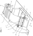
- a continuous sheet 7 fed from a continuous sheet feeding unit 8 is conveyed by a first main conveying roller pair 19 such that the continuous sheet 7 passes through an image forming unit (image forming means) 1 provided downstream the first main conveying roller pair 19 in a conveyance direction 15.
- a second main conveying roller pair 20 is provided downstream the image forming unit 1. The second main conveying roller pair 20 conveys the continuous sheet 7 from the image forming unit 1 to a cutting device.
- the image forming unit 1 includes recording heads that discharge ink of respective colors and are arranged in the conveyance direction.
- the recording heads are arranged for cyan, magenta, yellow, and black.
- Each recording head has a plurality of discharge nozzles to cover an entire width of the continuous sheet 7 so that the recording head can discharge ink for the entire width of the continuous sheet 7.
- the recording head discharges ink, in accordance with image information, on the continuous sheet 7 that is continuously conveyed at a constant speed by the first main conveying roller pair 19 and the second main conveying roller pair 20 (first conveying means), to successively form a plurality of images.
- the image forming unit 1 of the apparatus employs an inkjet recording method.
- the image forming unit 1 successively discharges ink of cyan, magenta, yellow, and black at a constant frequency without color misregistration.
- the continuous sheet 7 has to be conveyed at a constant printing conveyance speed Va. If the speed becomes lower than the printing conveyance speed Va, an image during image formation becomes a defective image. If the defective image is formed, the continuous sheet 7 during image formation has to be thrown away. This may increase running cost. In addition, printing has to be performed from the beginning again. This may reduce productivity.
- a blank portion (non-image portion) is formed between images because ink is not discharged on that portion.
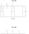
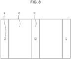
- the image forming unit 1 alternately forms an image portion 10 and a non-image portion 11 on the continuous sheet 7.
- a cutting mark 9 is printed on the non-image portion 11.
- the cutting mark 9 includes a record of cutting-position information for cutting by the cutting device.
- the cutting mark 9 serves as a reference for determining a cutting position.
- refreshing is performed by discharging ink, which is located near discharge ports of the discharge nozzles of the image forming unit 1 and has a high viscosity, on the non-image portion 11 at a predetermined time interval.
- a pattern for inspecting whether nozzles that discharge ink are capable of discharging ink or not, or a pattern for inspecting whether an image has a defect or not, is recorded at irregular timing.
- the non-image portion 11 may become long. Even in this case, the cutting mark 9 specifies the cutting position.
- Fig. 2A Ly is a length of the non-image portion 11.
- Fig. 2B is a schematic view from a side of the continuous sheet 7 shown in Fig. 2A .
- the image portion 10 is indicated by a solid line, and the non-image portion 11 is indicated by a broken line.
- the cutting mark 9 is provided on a side P of the broken line indicative of the non-image portion 11.
- the cutting device includes a first cutter 2 (first cutting means) provided downstream of the second main conveying roller pair 20, and a second cutter 3 (second cutting means) provided downstream of the first cutter 2.
- the first cutter 2 includes a movable blade 2m (first blade) and a fixed blade 2f (second blade).
- the continuous sheet 7 is cut when the movable blade 2m reciprocates in an up-down direction as shown in Fig. 5A .
- the second cutter 3 includes a movable blade 3m and a fixed blade 3f and has a configuration similar to the configuration of the first cutter 2.
- the fixed blade 2f is arranged at the upstream side in the conveyance direction, so in the direction 15 for the continuous sheet 7 (shown in Fig. 5A ), and the movable blade 2m is arranged at the downstream side in the conveyance direction.
- a printed surface of the continuous sheet 7 is the side P.
- the fixed blade 2f is constantly located closer to an image than the movable blade 2m, but the fixed blade 2f contacts a surface opposite the printed surface with an image.
- the movable blade 2m contacts the printed surface with an image, but the surface is the non-image portion 11.
- a movable blade position sensor (not shown) is provided and a movable blade actuator (cutter motor) is driven by a control means (see description of Fig. 3 below) in accordance with detection data of the movable blade position sensor.
- Control similar to the control for the first cutter 2 is provided for the second cutter 3 by the control means.
- First and second mark sensors 17 and 18 detect the cutting mark 9.
- the first cutter 2 includes the first mark sensor 17, and the second cutter 3 includes the second mark sensor 18.
- the first and second mark sensors 17 and 18 employ reflection-type sensors using photoelectric conversion. If the first and second mark sensors 17 and 18 detect the cutting mark 9, the continuous sheet 7 is conveyed by a predetermined distance and stopped. Then, the continuous sheet 7 is cut.
- a first conveying roller pair 4 (second conveying means) that conveys the continuous sheet 7 is arranged between the second main conveying roller pair 20 (first conveying means) and the first cutter 2.
- a second conveying roller pair 5 is arranged between the first cutter 2 and the second cutter 3.
- a third conveying roller pair 6 (third conveying means) is provided downstream of the second cutter 3.
- FIG. 3 is a control block diagram showing the image forming apparatus.
- a control circuit 300 (control means) includes a CPU 310, a ROM 311, and a RAM 312.
- the CPU 310 makes an instruction and a determination for control.
- the ROM 311 stores a program and a control table.
- the RAM 312 temporarily stores image information and control information.
- the control circuit 300 also includes drivers that drive various motors and heads.
- a first cutter motor 2a drives the first cutter 2.
- a second cutter motor 3a drives the second cutter 3.
- a first conveyance motor 4a drives a driving roller of the first conveying roller pair 4.
- a second conveyance motor 5a drives a driving roller of the second conveying roller pair 5.
- a third conveyance motor 6a drives a driving roller of the third conveying roller pair 6.
- Conveyance motor 19a drives the first main conveying roller pair 19 and the second main conveying roller pair 20.
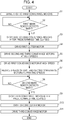
- the continuous sheet 7 is conveyed to a cutting device shown in Fig. 5A at the printing conveyance speed Va.
- the first conveyance motor 4a, the second conveyance motor 5a, and the third conveyance motor 6a are driven.
- the first conveying roller pair 4 and the second conveying roller pair 5 convey the continuous sheet 7 in the direction 15 at the printing conveyance speed Va.
- Fig. 5A illustrates a state in which a leading edge of the continuous sheet 7 with an image formed by the image forming unit 1 passes through the first cutter 2 and a trailing edge of the non-image portion 11 reaches a position at which the first cutter 2 can cut the trailing edge. If the first mark sensor 17 detects the cutting mark 9 of the non-image portion 11 in step S2, the first conveyance motor 4a, the second conveyance motor 5a, and the third conveyance motor 6a are stopped after a predetermined time elapses in step S3.
- the first conveying roller pair 4 and the second conveying roller pair 5 thus convey the continuous sheet 7 by a predetermined distance (in the predetermined time), and then stop the continuous sheet 7 when the trailing edge of the non-image portion 11 reaches a cutting position 2c at which the first cutter 2 cuts the trailing edge.
- Fig. 5A illustrates a state in which the first conveying roller pair 4 and the second conveying roller pair 5 pinch the continuous sheet 7.
- the continuous sheet 7 may be occasionally pinched only by the first conveying roller pair 4, or by all the first to third conveying roller pairs 4 to 6 depending on the length in the conveying direction of the image portion 10.
- step S4 the first cutter motor 2a is driven to move the movable blade 2m of the first cutter 2 in the direction indicated by arrow A in Fig. 5B .
- the trailing edge in the conveyance direction of the non-image portion 11 (downstream end in the conveyance direction of a second image 10b) of the continuous sheet 7 is cut at the cutting position 2c.
- Fig. 5B illustrates a state in which the cutting by the first cutter 2 is ended.
- the movable blade 2m moves in the direction indicated by arrow B.
- a gap is provided between the movable blade 2m and the fixed blade 2f so that the continuous sheet 7 is conveyed through the gap.
- the first to third conveying roller pairs 4 to 6 are stopped.
- the image forming unit 1 continuously performs a continuous printing operation.
- a sag or bulge (loop) 7-A of the continuous sheet 7 is generated at a position located upstream the first conveying roller pair 4 in the conveyance direction as shown in Fig. 5B .
- the arrangement of this embodiment is provided to prevent an image from being degraded due to cracking of the printed surface or due to a scratch because a guide (not shown) for the continuous sheet 7 slides on the printed surface by the sag 7-A.
- Fig. 5C illustrates a state in which the sag 7-A of the continuous sheet 7 is being reduced.
- the second conveyance motor 5a and the third conveyance motor 6a are driven at high speeds in step S5.
- the second and third conveying roller pairs 5 and 6 start rotating, and convey a cut sheet 21, which has been cut from the continuous sheet 7, at a high conveyance speed Vh that is higher than the printing conveyance speed Va.
- a gap D is generated between the cut sheet 21 and the continuous sheet 7.
- the first conveyance motor 4a is driven at a high speed, starts rotating, and conveys the continuous sheet 7 at the high conveyance speed Vh in step S6.
- the first to third conveying roller pairs 4 to 6 convey the continuous sheet 7 at the high conveyance speed Vh that is higher than the printing conveyance speed Va of the image forming unit 1.
- a sag length (loop length) of the sag 7-A of the continuous sheet 7 is reduced. That is, the sag 7-A becomes a sag (loop) 7-B. If the gap D is not generated between the cut sheet 21 and the continuous sheet 7, the continuous sheet 7 may contact the cut sheet 21 before or after the cutting.
- the conveyance of the continuous sheet 7 is interrupted, and the continuous sheet 7 is obliquely conveyed. Thus, cutting accuracy may be degraded, and a scratch or the like may be generated due to sliding on the printed surface. As the result, an image may be degraded.
- step S7 the speeds of the first conveyance motor 4a and the second conveyance motor 5a are reduced such that the conveyance speed of the continuous sheet 7 becomes the printing conveyance speed Va. At this time, the cut sheet 21 is continuously conveyed at the high conveyance speed Vh.
- a cutting time required for cutting a sheet by the first and second cutters 2 and 3 is Tc (sec).
- the cutting time Tc is a time from when the gap is present between the movable blade 2m and the fixed blade 2f as shown in Fig. 5A until the movable blade 2m has (i) moved in the direction indicated by arrow A, (ii) cut the sheet, (iii) moved in the direction indicated by arrow B, and (iv) returned to the original position.
- the cutting time Tc is a fraction of a second.
- the output of driving means for example, a DC motor, for the movable blade may be increased.
- a current value, an inductance of a wire, and the size of the motor have to be increased to increase the output torque. If the current is increased with the unchanged inductance, the sectional area of the wire has to be increased. As the result, the size of the motor is increased. This may increase the cost, and the size of the entire apparatus. If the size of the motor is increased, acceleration performance of the motor is increased. However, rotational inertia of the motor is also increased, and hence a time may be required to stop the motor. Also, if the inductance (the number of turns) of the wire is increased, electric time constant is increased, and hence a speed at startup may be low.
- the continuous sheet 7 is conveyed at the printing conveyance speed Va in the image forming unit 1, and conveyed by the first conveying roller pair 4 at the high conveyance speed Vh.
- Time required for elimination of the maximum sag length of continuous sheet 7 maximum sag length of continuous sheet 7 / reduced length per unit time of sag length of continuous sheet 7 .
- Ly is a length of the non-image portion 11 of the continuous sheet 7.
- Lc is a distance between the cutting position 2c by the first cutter 2 and a cutting position 3c by the second cutter 3.
- a relationship among Vh (mm/sec), Tc (sec), Va (mm/sec), Ly (mm), and Lc (mm) for the first and second cutters 2 and 3 according to the embodiment of the present invention is as follows: Lc ⁇ Ly ⁇ Vh ⁇ Tc ⁇ Va / Vh ⁇ Va
- step S8 If the second mark sensor 18 detects the edge of the cutting mark 9 of the cut sheet 21, which has been cut and separated from the continuous sheet 7, in step S8, the third conveyance motor 6a is stopped after a predetermined time elapses in step S9.
- the third conveying roller 6 conveys the cut sheet 21 by a predetermined distance until the leading edge of the non-image portion 11 reaches the cutting position 3c by the second cutter 3.
- step S10 the second cutter motor 3a is driven, so that an upstream end in the conveyance direction of a first image 10c is cut by the second cutter 3 and hence the non-image portion 11 located upstream the trailing edge of the cut sheet 21 is cut and separated at the cutting position 3c.
- one the first and second cutters 2 and 3 cuts the upstream end in the conveyance direction of the image of the continuous sheet 7, and the other cuts the downstream end in the conveyance direction of the same image. Accordingly, the printout can be cut and separated from the continuous sheet 7.
- the cut sheet 21 pinched by the third conveying roller pair 6 slips relative to the third conveying roller pair 6. The accuracy of the cutting position is reduced.
- the following control is performed.
- the movable blade position sensor (not shown) detects the end of the reciprocal operation by the movable blade 2m of the first cutter 2 shown in Fig. 5B .
- a time required for the leading edge of the non-image portion 11 of the cut sheet 21, cut and separated from the continuous sheet 7 by the first cutter 2, to be conveyed to the cutting position 3c by the second cutter 3 at the high conveyance speed Vh after the trailing edge of the non-image portion 11 is cut, is as follows: Lc ⁇ Ly / Vh .
- Tc is the time required for the second cutter 3 to perform the cutting operation
- the required time from when the first cutter 2 ends (completes) cutting and separating the cut sheet 21 to when the second cutter 3 ends (completes) cutting the non-image portion 11 of the cut sheet 21, is as follows: Lc ⁇ Ly / Vh + Tc sec
- a distance of the conveyance at the reduced speed that is the printing conveyance speed Va after the sag is eliminated, is subtracted from the distance (Lc - Ly) of the conveyance until the continuous sheet 7 reaches the trailing edge of the cut sheet 21 as follows: Lc ⁇ Ly ⁇ Vh ⁇ Tc ⁇ Va / Vh ⁇ Va mm .
- continuous sheet reach time (3) + (8) is expressed as follows: Tc ⁇ Va / Vh ⁇ Va + Lc ⁇ Ly ⁇ Vh ⁇ Tc ⁇ Va / Vh ⁇ Va / Va
- the respective constants are determined to satisfy a relationship as follows: Cut sheet non-image portion cut end time (6) ⁇ continuous sheet reach time (8).
- the respective constants are determined by a condition as follows: Lc ⁇ Ly / Vh + Tc ⁇ Tc ⁇ Va / Vh ⁇ Va + Lc ⁇ Ly ⁇ Vh ⁇ Tc ⁇ Va / Vh ⁇ Va / Va
- Fig. 6B illustrates a state in which the non-image portion 11 is cut and separated from the cut sheet 21 by the second cutter 3 before the leading edge 10-a of the continuous sheet 7 reaches the trailing edge of the non-image portion 11 of the cut sheet 21.
- the second cutter 3 ends the cutting operation such that the movable blade 3m at the upstream side in the conveyance direction reciprocates in the directions indicated by arrows A and B in Fig. 6B .
- step S11 the third conveyance motor 6a is driven, so that the cut sheet 21 is conveyed to the downstream side.
- the conveyance speed at this time may be the high speed or the low speed depending on the state at the downstream side.
- Fig. 6A when the non-image portion 11 of the cut sheet 21 is cut, the next non-image portion 11 approaches the first cutter 2. The operation for cutting the next non-image portion 11 is repeatedly performed from step S1.
- the printed surface of the continuous sheet 7 is at the side P.
- the movable blade 3m first blade contacts the non-image portion 11 on the printed surface and the fixed blade 3f (second blade) contacts the back surface of the printed surface. Even if a dye component or a pigment component in ink on the printed surface adheres to the movable blade 3m, the movable blade 3m contacts the non-image portion 11 of the continuous sheet 7 during the next cutting. The image quality of an image surface is not degraded due to re-transferring from the movable blade 3m by such adhesion.
- the different first and second cutters perform the separation between the upstream end of the image portion 10 and the non-image portion 11 and the separation between the downstream end of the image portion 10 and the non-image portion 11. Also, the sheet is conveyed at the higher speed Vh between the cutters than the speed in the image forming unit 1. With this configuration, even if a sag is generated for the continuous sheet 7, the sag can be reduced immediately.
- the continuous sheet 7 has to be stopped at short intervals at the upstream and downstream positions of the non-image portion 11, which is a relatively short portion.
- the sag may be increased.
- the increase of the sag may cause a coating on a surface of the continuous sheet 7 to become cracked or scratched.
- the loop is not increased, and can be eliminated.
- the continuous sheet 7 has a thickness of 100 ⁇ m or larger and printing at a high speed with a high quality is desired. In this case, the continuous sheet 7 has to be stopped during cutting. In this embodiment, even if the continuous sheet 7 with the thickness of 100 ⁇ m is conveyed at a high speed Vh in the image forming unit 1, the continuous sheet can be stopped without difficulty.
- the printed state detection pattern for measuring the printed state of an image can be printed at irregular timing.
- the quality of a printout can be increased.
- the length of the non-image portion 11 can be optimized in accordance with a length of an image and a use amount of ink for the image. An optimal image can be obtained while an ink consumption in the non-image portion is minimized. Thus, the running cost can be decreased.
- the length of the non-image portion can be changed in accordance with an image size and a process factor such as the presence of a duty for an image (e.g. what the image is required for).
- the length of the non-image portion 11 can be optimized for every image (so is preferably minimized).
- the amount of wasted continuous sheet 7 and the amount of wasted ink can be minimized in accordance with the length of the non-image portion 11.
- the running cost for printing can be decreased.
- the blade of the first or second cutter 2 or 3 does not contact the image portion on the printed surface. Even if the apparatus is used for a long period, fine (good quality) images can be obtained.
- the image forming apparatus includes a first main conveying roller pair 19 that conveys in a conveyance direction a continuous sheet 7 fed from a continuous sheet feeding unit 8.
- An image forming unit 1 includes a plurality of recording heads that print an image on the continuous sheet 7 being conveyed in the conveyance direction.
- the image forming unit 1 forms images while forming a blank portion (non-image portion) between the images.
- a first conveying roller pair 41, a second conveying roller pair 51, and a third conveying roller pair 6 which convey the continuous sheet 7; a first mark sensor 17, a first cutter 2, and a second cutter 3 are provided downstream of the image forming unit 1.
- the position of the first cutter 2 and the position at which a sag of the continuous sheet 7 is formed are different from those of the first embodiment.
- the control block diagram in Fig. 3 can be referenced.
- the second embodiment will be described also with reference to Fig. 3 .
- the image forming unit 1 alternately forms an image portion 10 and a non-image portion 11 on the continuous sheet 7 as shown in Fig. 8 . Also, the image forming unit 1 prints a cutting mark 9 on the non-image portion 11.
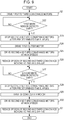
- step S21 a first conveyance motor 4a, a second conveyance motor 5a, and a third conveyance motor 6a are driven, so that the first conveying roller pair 41, the second conveying roller pair 51, and the third conveying roller pair 6 convey the continuous sheet 7 in a direction 15. If the first mark sensor 17 detects the cutting mark 9 in step S22, the second conveyance motor 5a and the third conveyance motor 6a are stopped after a predetermined time elapses in step S23.
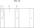
- the continuous sheet 7 includes an image portion 13, a first non-image portion 12, and a second non-image portion 14. Referring to Fig. 10A , the continuous sheet 7 is stopped at a position at which a downstream end of the first non-image portion 12 can be cut by the first cutter 2.
- the second conveying roller pair 51 and the third conveying roller pair 6 stop the conveyance, in order to improve the perpendicularity of the cut surface of the sheet.
- another mark sensor (second mark sensor 18, not shown) may be provided upstream the second cutter 3 to increase conveyance accuracy.
- step S24 the first cutter motor 2a is driven, so that the first cutter 2 cuts the downstream end of the first non-image portion 12.
- a sag length (loop length) is equivalent to a conveyed distance by the first conveying roller pair 41 while the second conveying roller pair 51 is stopped during the cutting.
- step S25 the second conveyance motor 5a and the third conveyance motor 6a are driven at high speeds to eliminate the sag.
- the generated sag is eliminated when the second conveying roller pair 51 is rotated at a high speed after the cutting is ended.
- a conveyance speed Vh of the second conveying roller pair 51 at this time has to be at least a speed that allows the sag to be eliminated before the second non-image portion 14 reaches the first cutter 2.
- a distance by which the first conveying roller pair 41 conveys the second non-image portion 14 during the sag elimination time is as follows: Va Tc ⁇ Va / Vh ⁇ Va
- Expression 15 is the condition that allows the sag to be eliminated before the second non-image portion 14 reaches the first cutter 2.
- the third conveying roller pair 6 conveys the sheet at a rotation speed that is equal to or higher than a speed of the second conveying roller pair 51 that is eliminating the sag.
- step S27 If the second mark sensor 18 detects the cutting mark 9 in step S27, the second conveyance motor 5a and the third conveyance motor 6a are stopped after a predetermined time elapses in step S28.
- the continuous sheet 7 is conveyed to and stopped at a position as shown in Fig. 11A , the position at which the second cutter 3 can cut and separate the first non-image portion 12 from the image portion 13.
- step S29 the second cutter motor 3a is driven, so that the first non-image portion 12 is cut and separated from the image portion 13.
- Fig. 11B illustrates a sag (loop) generated during the above situation.
- the sag is generated at a position located upstream the second conveying roller pair 51 in the conveyance direction.
- a sag length (loop length) is equivalent to a conveyed distance by the first conveying roller pair 41 while the second conveying roller pair 51 is stopped during the cutting.
- a distance by which the first conveying roller pair 41 conveys the second non-image portion 14 during the sag elimination time is as follows: Va Tc ⁇ Va / Vh ⁇ Va
- a distance, by which the first conveying roller pair 41 conveys the second non-image portion 14 from the state shown in Fig. 11A to the formation of the sag is as follows: Tc ⁇ Va
- a distance by which the first conveying roller pair 41 conveys the second non-image portion 14 until the elimination of the sag is as follows: Va Tc ⁇ Va / Vh ⁇ Va
- Expression 23 is a condition that the second non-image portion 14 does not reach the cutting position at the first cutter 2 even if the first non-image portion 12 is cut from the state shown in Fig. 11A and the sag generated during the cutting is eliminated.
- the third conveying roller pair 6 conveys the sheet at a rotation speed that is equal to or higher than a speed of the second conveying roller pair 51 that is eliminating the sag.
- the speeds of the second conveying roller pair 51 and the third conveying roller pair 6 are reduced to a printing conveyance speed in step S31.
- step S23 the continuous sheet 7 is stopped at a position at which a downstream end of the second non-image portion 14 can be cut by the first cutter 2. Even during this stoppage, the image forming unit 1 continuously performs the printing, and the first conveying roller pair 41 continuously performs the conveyance.
- Fig. 12B illustrates a state in which the first cutter 2 cuts the second non-image portion 14. By cutting a leading edge of the second non-image portion 14, the cutting for the image portion 13 is ended, and hence only the image portion can be cut and obtained.
- Fig. 12B illustrates the same state as the state shown in Fig. 10B . The operation continues to the cutting for the next image portion 16.
- a conditional expression by which this embodiment is established is as follows: Tc ⁇ Va / Vh ⁇ Ly + cut length / Va and Cut length ⁇ Lc + Va 2 ⁇ Tc / Vh ⁇ Va
- Va is a conveyance speed by the first conveying roller pair 41
- Tc is a stop time of the second conveying roller pair 51 during the cutting
- Vh is a high conveyance speed of the second conveying roller pair 51 during the elimination of the sag
- Lc is a distance between the cutting position by the first cutter 2 and the cutting position by the second cutter 3
- Ly is a length of the non-image portion.
- the cut length is substantially equivalent to a length in the conveyance direction of the image portion 13. If a printout without a margin is formed, the cut length becomes smaller than the length of the image portion 13 in the conveyance direction. If a printout with margins is formed, the cut length becomes larger than the length of the image portion 13.
- Expression 24 is a condition that is satisfied by a next portion to be cut by the first cutter 2 after the sag generated during the cutting by the second cutter 3 is eliminated.
- Expression 25 is a condition for the cutting operation by the second cutter 3 after the sag generated by cutting by the first cutter 2 is eliminated.
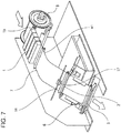
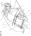
- Fig. 13 illustrates a configuration of an image forming apparatus according to the third example.
- Figs. 15A and 15B illustrate the details of an operation according to this example.
- the control block as illustrated in Fig. 3 , is used to implement the third example.
- the image forming apparatus includes a main conveying roller pair 22 that conveys in a conveyance direction a continuous sheet 7 fed from a continuous sheet feeding unit 8.
- An image forming unit 1 continuously prints images on the continuous sheet 7 by the main conveying roller pair 22 while forming a blank portion (non-image portion) between the images.
- a first conveying roller pair 4, a second conveying roller pair 5, and a third conveying roller pair 6, which convey the continuous sheet 7 from the image forming unit 1 to a cutting device, are provided downstream the image forming unit 1.
- a mark sensor 17 that detects a cutting mark in the non-image portion, and a first cutter 2 and a second cutter 3 are arranged.
- the second cutter 3 is movable along guide shafts 23 and 24 arranged in parallel to the conveyance direction.
- the distance between the first and second cutters 2 and 3 is adjustable in accordance with a desirable cut length.
- the adjustment is performed by a timing belt 25 and a motor 26.
- a cut length is equivalent to a length in the conveyance direction of the image portion 13.
- the cut length becomes shorter than the length in the conveyance direction of the image portion if the end of the image is trimmed, or larger than the length in the conveyance direction of the image portion if the image has a binding margin, depending on a formation mode of a printout.
- the image forming unit 1 alternately forms on the continuous sheet 7 the image portion 13 with an image formed in accordance with image information, and first and second non-image portions 12 and 14 without an image.
- the image forming unit 1 also prints cutting marks 9 in the first and second non-image portions 12 and 14. If the mark sensor 17 detects the cutting mark 9, the continuous sheet 7 is fed by a predetermined length, located at predetermined positions, and cut by the first and second cutters 2 and 3. Thus, the image portion 13 is cut and separated.
- the second conveying roller pair 5 and the third conveying roller pair 6 stop the conveyance, in order to improve the perpendicularity of the cut surface of the sheet.
- Fig. 15A the continuous sheet 7 is conveyed in a direction 15.
- the motor 26 moves the second cutter 3. Accordingly, the distance between the cutting position by the first cutter 2 and the cutting position by the second cutter 3 can be changed. The distance between the cutting position by the first cutter 2 and the cutting position by the second cutter 3 is adjusted to be equivalent to the desirable cut length (the length of the image portion 13 in the conveyance direction).
- An exemplary arrangement of the image portion 13, the first non-image portion 12, and the second non-image portion 14 on the continuous sheet 7 is illustrated in Fig. 15A .
- a cutting method while the continuous sheet 7 is conveyed according to the third example will be described on the basis of the state illustrated in Fig. 15A .
- the continuous sheet 7 is stopped at a position at which the first non-image portion 12 located downstream of the image portion 13 can be cut and separated by the second cutter 3 and at which the second non-image portion 14 located upstream the image portion 13 can be cut and separated by the first cutter 2. While the second conveying roller pair 5 and the third conveying roller pair 6 are stopped, the image forming unit 1 continuously performs the printing, and the first conveying roller pair 4 continuously perform the conveyance.
- Fig. 15B illustrates a sag (loop) generated during the above situation.
- the sag is generated at a position located upstream of the second conveying roller pair 5.
- a sag length (loop length) is equivalent to a conveyed distance by the first conveying roller pair 4 while the second conveying roller pair 5 is stopped during the cutting.
- the generated sag is eliminated when the second conveying roller pair 5 is rotated at a high speed after the cutting is ended.
- a conveyance speed Vh of the second conveying roller pair 5 at this time has to be at least a speed that allows the sag to be eliminated before the third non-image portion 27 reaches the first cutter 2. This is provided as a conditional expression that establishes the third example.
- the third conveying roller pair 6 conveys the sheet at a rotation speed that is equal to or higher than a speed of the second conveying roller pair 5 that is eliminating the sag.
- the second embodiment may be combined with the third example.
- a conditional expression to which the second embodiment and third example are applicable is given below.
- a sag length (loop length) formed during the cutting is as follows: Tc ⁇ Va
- a distance, by which the first conveying roller pair 4 conveys the continuous sheet 7 from the state shown in Fig. 15A to the formation of the sag is as follows: Tc ⁇ Va
- a distance by which the first conveying roller pair 4 conveys the second non-image portion 14 until the elimination of the sag is as follows: Va Tc ⁇ Va / Vh ⁇ Va
- Va is a conveyance speed by the first conveying roller pair 4
- Tc is a stop time of the second conveying roller pair 5 during the cutting
- Vh is a high conveyance speed of the second conveying roller pair 5 during elimination of the sag
- Lc is a distance between the cutting position by the first cutter 2 and the cutting position by the second cutter 3
- Ly is a length of the non-image portion.
- Expression 31 is a condition that the third non-image portion 27 does not reach the cutting position at the first cutter 2 even if the image portion 13 is cut from the state shown in Fig. 15A and the sag generated during the cutting is eliminated.
- the cutting method according to the third example is effective because the cutting method can deal with a plurality of cut lengths as long as it satisfies conditions given below.
- Conditional expressions of this example is as follows: Cut length ⁇ Lc Vh ⁇ Va ⁇ cut length + Ly / Va ⁇ Va ⁇ Tc and Cut length ⁇ Lc + Va 2 ⁇ Tc / Vh ⁇ Va
- Expression 32, 33, and 34 are conditions that allow the sag to be continuously eliminated.
- the accuracy for the cut position can be increased irrespective of the accuracy for the conveyance of the continuous sheet 7. Also, an image with a small size can be cut.
Claims (10)
- Bilderzeugungsvorrichtung, die eine Bilderzeugungseinheit (1) enthält, welche konfiguriert ist, nacheinander ein erstes Bild (10) und ein zweites Bild (10) auf einem Endlosbogen (7) zu erzeugen, und die einen bildlosen Abschnitt (11) ausschneidet, welcher zwischen einem ersten Abschnitt, auf dem das erste Bild erzeugt ist, und einem zweiten Abschnitt, auf dem das zweite Bild erzeugt ist, liegt, um einen ersten Ausdruck herzustellen, auf dem das erste Bild erzeugt ist, und einen zweiten Ausdruck, auf dem das zweite Bild erzeugt ist, wobei die Bilderzeugungsvorrichtung der Reihe nach in Beförderungsrichtung des Endlosbogens (7) stromabwärts der Bilderzeugungseinheit (1) und umfasst: eine erste Beförderungseinrichtung (20), welche konfiguriert ist, den Endlosbogen zu befördern, eine zweite Beförderungseinrichtung (4), welche konfiguriert ist, den Endlosbogen zu befördern, eine erste Schneideeinrichtung (2), welche konfiguriert ist, den Endlosbogen zu schneiden, und eine zweite Schneideeinrichtung (3), welche konfiguriert ist, den Endlosbogen zu schneiden, dadurch gekennzeichnet, dass die Bilderzeugungsvorrichtung ferner eine Steuereinrichtung (300) umfasst, welche konfiguriert ist, die zweite Beförderungseinrichtung (4) zu veranlassen, anzuhalten, während sie die erste Beförderungseinrichtung (20) veranlasst, den Endlosbogen mit einer ersten Beförderungsgeschwindigkeit (Va) zu befördern, sodass der Endlosbogen eine Schlaufe bildet, und die erste Schneideeinrichtung (2) zu veranlassen, einen auf einer Seite des zweiten Abschnitts gelegenen Endabschnitt des bildlosen Abschnitts (11) zu schneiden, und danach die zweite Beförderungseinrichtung (4) zu veranlassen, den Endlosbogen mit einer zweiten Beförderungsgeschwindigkeit (Vh) höher als die erste Beförderungsgeschwindigkeit (Va) zu befördern, sodass die Schlaufe des Endlosbogens verkleinert wird, und die zweite Schneideeinrichtung (3) zu veranlassen, einen auf einer Seite des ersten Abschnitts gelegenen Endabschnitt des bildlosen Abschnitts (11) zu schneiden.
- Bilderzeugungsvorrichtung, die eine Bilderzeugungseinheit (1) enthält, welche konfiguriert ist, nacheinander ein erstes Bild (10) und ein zweites Bild (10) auf einem Endlosbogen (7) zu erzeugen, und die einen bildlosen Abschnitt (11) ausschneidet, welcher zwischen einem ersten Abschnitt, auf dem das erste Bild erzeugt ist, und einem zweiten Abschnitt, auf dem das zweite Bild erzeugt ist, liegt, um einen ersten Ausdruck herzustellen, auf dem das erste Bild erzeugt ist, und einen zweiten Ausdruck, auf dem das zweite Bild erzeugt ist, wobei die Bilderzeugungsvorrichtung der Reihe nach in Beförderungsrichtung des Endlosbogens stromabwärts der Bilderzeugungseinheit umfasst: eine erste Beförderungseinrichtung (41), welche konfiguriert ist, den Endlosbogen zu befördern, eine zweite Beförderungseinrichtung (51), welche konfiguriert ist, den Endlosbogen (7) zu befördern, eine erste Schneideeinrichtung (2), welche konfiguriert ist, den Endlosbogen zu schneiden, und eine zweite Schneideeinrichtung (3), welche konfiguriert ist, den Endlosbogen zu schneiden, dadurch gekennzeichnet, dass die Bilderzeugungsvorrichtung ferner eine Steuereinrichtung (300) umfasst, welche konfiguriert ist, die zweite Beförderungseinrichtung (51) zu veranlassen, anzuhalten, während sie die erste Beförderungseinrichtung (41) veranlasst, den Endlosbogen mit einer ersten Beförderungsgeschwindigkeit (Va) zu befördern, sodass der Endlosbogen eine Schlaufe bildet, und die erste Schneideeinrichtung (2) zu veranlassen, einen auf einer Seite des ersten Abschnitts gelegenen Endabschnitt des bildlosen Abschnitts (11) zu schneiden, und danach die zweite Beförderungseinrichtung (51) zu veranlassen, den Endlosbogen mit einer zweiten Beförderungsgeschwindigkeit (Vh) höher als die erste Beförderungsgeschwindigkeit (Va) zu befördern, sodass die Schlaufe des Endlosbogens verkleinert wird, und die zweite Schneideeinrichtung (3) zu veranlassen, einen auf einer Seite des zweiten Abschnitts gelegenen Endabschnitt des bildlosen Abschnitts (11) zu schneiden.
- Bilderzeugungsvorrichtung nach Anspruch 1 oder 2, wobei die erste Schneideeinrichtung (2) und die zweite Schneideeinrichtung (3) in einer Weise angeordnet sind, dass ein Abstand (Lc) zwischen einer Schneideposition der ersten Schneideeinrichtung (2) und einer Schneideposition der zweiten Schneideeinrichtung (3) länger als eine Länge (Ly) des bildlosen Abschnitts (11) in der Beförderungsrichtung ist.
- Bilderzeugungsvorrichtung nach Anspruch 3, wobei die Bilderzeugungsvorrichtung folgenden Ausdruck erfüllt:

- Bilderzeugungsvorrichtung nach einem der Ansprüche 1 bis 4, wobei die erste Schneideeinrichtung (2) eine erste bewegbare Klinge (2m) auf einer Seite einer Fläche des Endlosbogens (7) enthält, auf welcher das Bild von der Bilderzeugungseinheit (1) erzeugt ist, sowie eine erste fixierte Klinge (2f) enthält, die in Beförderungsrichtung stromaufwärts der ersten bewegbaren Klinge (2m) angeordnet und auf einer Rückseite der Fläche des Endlosbogens (7) vorgesehen ist, und die zweite Schneideeinrichtung (3) eine zweite bewegbare Klinge (3m) auf der Seite der Fläche des Endlosbogens (7) enthält, auf welcher das Bild erzeugt ist, sowie eine zweite fixierte Klinge (3f) enthält, die in Beförderungsrichtung stromabwärts der zweiten bewegbaren Klinge (3m) angeordnet und auf der Rückseite der Fläche vorgesehen ist.
- Bilderzeugungsvorrichtung nach einem der Ansprüche 1 bis 5, wobei eine zum Schneiden des Endlosbogens (7) durch die erste Schneideeinrichtung (2) oder die zweite Schneideinrichtung (3) verwendete Markierung (9) auf den bildlosen Abschnitt (11) gedruckt ist, und wobei die Bilderzeugungsvorrichtung ferner einen Markierungserkennungssensor (17, 18) umfasst, der konfiguriert ist, die Markierung (9) zu erkennen.
- Bilderzeugungsvorrichtung nach einem der Ansprüche 1 bis 6, wobei die Bilderzeugungseinheit (1) einen mit mehreren Düsen zum Ausstoßen von Tinte versehenen Aufzeichnungskopf enthält, wobei die mehreren Düsen dem Endlosbogen gegenüberliegend angeordnet sind, sodass sie eine gesamte Breite des Endlosbogens (7) abdecken.
- Bilderzeugungsvorrichtung nach Anspruch 7, wobei der Endlosbogen (7) mit der ersten Beförderungsgeschwindigkeit (Va) befördert wird, wenn der Aufzeichnungskopf einen Aufzeichnungsvorgang durchführt.
- Bilderzeugungsvorrichtung nach einem der Ansprüche 1 bis 8, wobei der Endlosbogen (7) eine Stärke von 100 µm oder mehr aufweist.
- Verfahren zum Herstellen eines ersten Ausdrucks und eines zweiten Ausdrucks durch eine Bilderzeugungsvorrichtung, die der Reihe nach in Beförderungsrichtung eines Endlosbogens (7) stromabwärts einer Bilderzeugungseinheit (1) umfasst: eine erste
Beförderungseinrichtung (20), welche konfiguriert ist, den Endlosbogen zu befördern, eine zweite Beförderungseinrichtung (4), welche konfiguriert ist, den Endlosbogen zu befördern, eine erste Schneideeinrichtung (2), welche konfiguriert ist, den Endlosbogen zu schneiden, und eine zweite Schneideeinrichtung (3), welche konfiguriert ist, den Endlosbogen zu schneiden, und die unter Verwendung der Bilderzeugungseinheit nacheinander ein erstes Bild und ein zweites Bild auf dem Endlosbogen (7) erzeugt und einen bildlosen Abschnitt (11) ausschneidet, welcher zwischen einem ersten Abschnitt, auf dem das erste Bild erzeugt ist, und einem zweiten Abschnitt, auf dem das zweite Bild erzeugt ist, liegt, wobei das Verfahren in folgender Abfolge umfasst:Erzeugen des ersten Bildes (10) und des zweiten Bildes (10) nacheinander auf dem Endlosbogen (7) durch die Bilderzeugungseinheit (1);dadurch gekennzeichnet, dass das Verfahren ferner umfasst:Anhalten der zweiten Beförderungseinrichtung (4) während des Beförderns des Endlosbogens mit einer ersten Beförderungsgeschwindigkeit (Va) durch die erste Beförderungseinrichtung (20), sodass der Endlosbogen eine Schlaufe bildet, und Schneiden eines auf einer Seite des zweiten Abschnitts gelegenen Endabschnitts des bildlosen Abschnitts (11) durch die erste Schneideeinrichtung (2);Befördern des Endlosbogens durch die zweite Beförderungseinrichtung (4) mit einer zweiten Beförderungsgeschwindigkeit (Vh), die höher als die erste Beförderungsgeschwindigkeit (Va) ist, sodass die Schlaufe des Endlosbogens (7) verkleinert wird; undSchneiden eines auf einer Seite des ersten Abschnitts gelegenen Endabschnitts des bildlosen Abschnitts durch die zweite Schneideeinrichtung (3).
Applications Claiming Priority (2)
| Application Number | Priority Date | Filing Date | Title |
|---|---|---|---|
| JP2010041662A JP5213892B2 (ja) | 2010-02-26 | 2010-02-26 | 画像形成装置および切断装置 |
| EP11155602.3A EP2361737B1 (de) | 2010-02-26 | 2011-02-23 | Bilderzeugungsvorrichtung und Schneidegerät |
Related Parent Applications (1)
| Application Number | Title | Priority Date | Filing Date |
|---|---|---|---|
| EP11155602.3A Division EP2361737B1 (de) | 2010-02-26 | 2011-02-23 | Bilderzeugungsvorrichtung und Schneidegerät |
Publications (2)
| Publication Number | Publication Date |
|---|---|
| EP2700483A1 EP2700483A1 (de) | 2014-02-26 |
| EP2700483B1 true EP2700483B1 (de) | 2019-09-04 |
Family
ID=44121435
Family Applications (2)
| Application Number | Title | Priority Date | Filing Date |
|---|---|---|---|
| EP11155602.3A Active EP2361737B1 (de) | 2010-02-26 | 2011-02-23 | Bilderzeugungsvorrichtung und Schneidegerät |
| EP13172332.2A Active EP2700483B1 (de) | 2010-02-26 | 2011-02-23 | Bilderzeugungsvorrichtung und Schneidegerät |
Family Applications Before (1)
| Application Number | Title | Priority Date | Filing Date |
|---|---|---|---|
| EP11155602.3A Active EP2361737B1 (de) | 2010-02-26 | 2011-02-23 | Bilderzeugungsvorrichtung und Schneidegerät |
Country Status (4)
| Country | Link |
|---|---|
| US (1) | US9289914B2 (de) |
| EP (2) | EP2361737B1 (de) |
| JP (1) | JP5213892B2 (de) |
| CN (1) | CN102189829B (de) |
Families Citing this family (18)
| Publication number | Priority date | Publication date | Assignee | Title |
|---|---|---|---|---|
| US20110211899A1 (en) * | 2010-02-26 | 2011-09-01 | Canon Kabushiki Kaisha | Print control method and print apparatus |
| JP5372037B2 (ja) * | 2011-02-01 | 2013-12-18 | キヤノン株式会社 | プリント方法およびプリント装置 |
| JP6039172B2 (ja) * | 2011-10-21 | 2016-12-07 | キヤノン株式会社 | シート切断装置およびプリンタ |
| JP2014172280A (ja) * | 2013-03-08 | 2014-09-22 | Ricoh Co Ltd | 画像形成装置 |
| JP6150595B2 (ja) * | 2013-04-16 | 2017-06-21 | キヤノン株式会社 | プリント装置およびプリント方法 |
| JP5967383B2 (ja) * | 2014-03-18 | 2016-08-10 | コニカミノルタ株式会社 | 後処理装置および画像形成システム |
| JP6312043B2 (ja) * | 2014-05-23 | 2018-04-18 | 富士ゼロックス株式会社 | 画像形成装置、裁断処理装置、印刷システム及びプログラム |
| CN104444541B (zh) * | 2015-01-09 | 2017-07-28 | 京东方光科技有限公司 | 一种胶带切割装置 |
| CN104589809A (zh) * | 2015-02-08 | 2015-05-06 | 李丽容 | 一种用于票据打印机的自动切纸部件 |
| DE102015213544A1 (de) | 2015-07-17 | 2017-01-19 | Cewe Stiftung & Co. Kgaa | Vorrichtung zum Erzeugen von Aufklebern |
| WO2017013779A1 (ja) * | 2015-07-23 | 2017-01-26 | ホリゾン・インターナショナル株式会社 | シート断裁装置 |
| CN106476070A (zh) * | 2015-11-25 | 2017-03-08 | 衡阳唯美印务有限公司 | 一种自动纸张切割机 |
| JP6458724B2 (ja) * | 2015-12-25 | 2019-01-30 | ブラザー工業株式会社 | 印刷装置 |
| CN106219303B (zh) * | 2016-07-29 | 2017-08-25 | 广州市程翔机械有限公司 | 胶条检测裁断与排料系统 |
| CN106241475B (zh) * | 2016-08-31 | 2018-11-20 | 上海良劲自动化科技有限公司 | 追踪定长裁切系统 |
| JP6990400B2 (ja) * | 2017-10-02 | 2022-02-03 | デュプロ精工株式会社 | 帯状物切断装置 |
| JP7427941B2 (ja) | 2019-12-04 | 2024-02-06 | コニカミノルタ株式会社 | 画像形成装置及びプログラム |
| JP7457570B2 (ja) * | 2020-05-14 | 2024-03-28 | キヤノン株式会社 | 記録装置及びその搬送制御方法 |
Family Cites Families (13)
| Publication number | Priority date | Publication date | Assignee | Title |
|---|---|---|---|---|
| JPS60137765A (ja) | 1983-12-26 | 1985-07-22 | Kawasaki Steel Corp | コイルシヤ−ラインの尾端切断制御方法 |
| JPS60137765U (ja) * | 1984-02-20 | 1985-09-12 | 株式会社東芝 | エレベ−タ−のインジケ−タ− |
| JPH07304220A (ja) * | 1994-05-12 | 1995-11-21 | Hitachi Ltd | プリンタ装置 |
| JP3688433B2 (ja) * | 1997-06-13 | 2005-08-31 | 三菱電機株式会社 | 印画装置 |
| FI105463B (fi) * | 1999-01-22 | 2000-08-31 | Valmet Corp | Menetelmä ja laite paperirainan rullauksessa |
| JP2001105383A (ja) * | 1999-10-05 | 2001-04-17 | Fuji Photo Film Co Ltd | シート切断装置 |
| JP2001310849A (ja) * | 2000-04-28 | 2001-11-06 | Konica Corp | 画像記録装置 |
| JP2003054044A (ja) * | 2001-08-21 | 2003-02-26 | Fuji Photo Film Co Ltd | 画像記録装置 |
| JP2003211755A (ja) | 2002-01-25 | 2003-07-29 | Seiko Epson Corp | 印刷装置、印刷システムおよびプリンタドライバ |
| JP4406923B2 (ja) * | 2004-03-10 | 2010-02-03 | ブラザー工業株式会社 | ラベル作成装置 |
| WO2007013263A1 (ja) | 2005-07-27 | 2007-02-01 | Mitsubishi Electric Corporation | 印刷装置及び印刷方法 |
| JP2009233915A (ja) * | 2008-03-26 | 2009-10-15 | Sato Knowledge & Intellectual Property Institute | カッタ付きプリンタ |
| JP2010155388A (ja) * | 2008-12-26 | 2010-07-15 | Olympus Corp | 画像記録装置、及び画像記録装置の制御方法 |
-
2010
- 2010-02-26 JP JP2010041662A patent/JP5213892B2/ja active Active
- 2010-12-10 US US12/965,724 patent/US9289914B2/en active Active
-
2011
- 2011-02-22 CN CN201110042049.XA patent/CN102189829B/zh active Active
- 2011-02-23 EP EP11155602.3A patent/EP2361737B1/de active Active
- 2011-02-23 EP EP13172332.2A patent/EP2700483B1/de active Active
Non-Patent Citations (1)
| Title |
|---|
| None * |
Also Published As
| Publication number | Publication date |
|---|---|
| EP2361737B1 (de) | 2013-12-11 |
| US20110211900A1 (en) | 2011-09-01 |
| CN102189829A (zh) | 2011-09-21 |
| EP2700483A1 (de) | 2014-02-26 |
| CN102189829B (zh) | 2016-07-06 |
| JP2011177909A (ja) | 2011-09-15 |
| US9289914B2 (en) | 2016-03-22 |
| EP2361737A1 (de) | 2011-08-31 |
| JP5213892B2 (ja) | 2013-06-19 |
Similar Documents
| Publication | Publication Date | Title |
|---|---|---|
| EP2700483B1 (de) | Bilderzeugungsvorrichtung und Schneidegerät | |
| US9132674B2 (en) | Printer and control method of a printer | |
| US9896298B2 (en) | Apparatus and method for cutting sheet | |
| US7607661B2 (en) | Control device, conveyance control device, conveyance system and image forming system | |
| CN101905569B (zh) | 打印装置 | |
| US7367732B2 (en) | Method and apparatus for controlling the sheet feeding speed in a printer | |
| CN106965552B (zh) | 打印方法和打印设备 | |
| US20120204693A1 (en) | Recording medium cutting apparatus | |
| US20120051824A1 (en) | Printing apparatus | |
| US8767224B2 (en) | Recording device and recording and cutting control method | |
| US8459766B2 (en) | Print apparatus and control method thereof | |
| US8408828B2 (en) | Image recording apparatus | |
| US20040141021A1 (en) | Image recording apparatus and image recording method | |
| US11912019B2 (en) | Printing apparatus | |
| US20210229475A1 (en) | Liquid discharge apparatus | |
| JP3941683B2 (ja) | シリアル式印刷装置における印刷媒体搬送制御装置、シリアル式印刷装置、印刷媒体搬送制御装置及び印刷媒体搬送制御方法 | |
| JP2007007967A (ja) | 切断装置及び該切断装置を備えた画像形成装置 | |
| CN114803585A (zh) | 印刷装置以及印刷装置的控制方法 | |
| JPH09295721A (ja) | シート給送装置及び画像形成装置 | |
| JP4466636B2 (ja) | 印刷装置における印刷媒体搬送制御装置、シリアル式印刷装置及び印刷媒体搬送制御方法 | |
| JP2008229979A (ja) | 印刷方法とその印刷方法を使用する装置 | |
| JP4428377B2 (ja) | 印刷装置における印刷媒体搬送制御装置及びシリアル式印刷装置 | |
| JP2005014496A (ja) | 被記録材及び記録装置並びに被記録材の記録位置設定方法 | |
| JP2019181844A (ja) | 記録装置、及びその制御方法 | |
| JP2024011675A (ja) | 記録装置、制御方法、およびプログラム |
Legal Events
| Date | Code | Title | Description |
|---|---|---|---|
| PUAI | Public reference made under article 153(3) epc to a published international application that has entered the european phase |
Free format text: ORIGINAL CODE: 0009012 |
|
| AC | Divisional application: reference to earlier application |
Ref document number: 2361737 Country of ref document: EP Kind code of ref document: P |
|
| AK | Designated contracting states |
Kind code of ref document: A1 Designated state(s): AL AT BE BG CH CY CZ DE DK EE ES FI FR GB GR HR HU IE IS IT LI LT LU LV MC MK MT NL NO PL PT RO RS SE SI SK SM TR |
|
| 17P | Request for examination filed |
Effective date: 20140826 |
|
| RBV | Designated contracting states (corrected) |
Designated state(s): AL AT BE BG CH CY CZ DE DK EE ES FI FR GB GR HR HU IE IS IT LI LT LU LV MC MK MT NL NO PL PT RO RS SE SI SK SM TR |
|
| STAA | Information on the status of an ep patent application or granted ep patent |
Free format text: STATUS: EXAMINATION IS IN PROGRESS |
|
| 17Q | First examination report despatched |
Effective date: 20180626 |
|
| GRAP | Despatch of communication of intention to grant a patent |
Free format text: ORIGINAL CODE: EPIDOSNIGR1 |
|
| STAA | Information on the status of an ep patent application or granted ep patent |
Free format text: STATUS: GRANT OF PATENT IS INTENDED |
|
| INTG | Intention to grant announced |
Effective date: 20190412 |
|
| GRAS | Grant fee paid |
Free format text: ORIGINAL CODE: EPIDOSNIGR3 |
|
| GRAA | (expected) grant |
Free format text: ORIGINAL CODE: 0009210 |
|
| STAA | Information on the status of an ep patent application or granted ep patent |
Free format text: STATUS: THE PATENT HAS BEEN GRANTED |
|
| AC | Divisional application: reference to earlier application |
Ref document number: 2361737 Country of ref document: EP Kind code of ref document: P |
|
| AK | Designated contracting states |
Kind code of ref document: B1 Designated state(s): AL AT BE BG CH CY CZ DE DK EE ES FI FR GB GR HR HU IE IS IT LI LT LU LV MC MK MT NL NO PL PT RO RS SE SI SK SM TR |
|
| REG | Reference to a national code |
Ref country code: GB Ref legal event code: FG4D |
|
| REG | Reference to a national code |
Ref country code: CH Ref legal event code: EP |
|
| REG | Reference to a national code |
Ref country code: AT Ref legal event code: REF Ref document number: 1174730 Country of ref document: AT Kind code of ref document: T Effective date: 20190915 |
|
| REG | Reference to a national code |
Ref country code: DE Ref legal event code: R096 Ref document number: 602011061901 Country of ref document: DE |
|
| REG | Reference to a national code |
Ref country code: IE Ref legal event code: FG4D |
|
| REG | Reference to a national code |
Ref country code: NL Ref legal event code: MP Effective date: 20190904 |
|
| REG | Reference to a national code |
Ref country code: LT Ref legal event code: MG4D |
|
| PG25 | Lapsed in a contracting state [announced via postgrant information from national office to epo] |
Ref country code: BG Free format text: LAPSE BECAUSE OF FAILURE TO SUBMIT A TRANSLATION OF THE DESCRIPTION OR TO PAY THE FEE WITHIN THE PRESCRIBED TIME-LIMIT Effective date: 20191204 Ref country code: SE Free format text: LAPSE BECAUSE OF FAILURE TO SUBMIT A TRANSLATION OF THE DESCRIPTION OR TO PAY THE FEE WITHIN THE PRESCRIBED TIME-LIMIT Effective date: 20190904 Ref country code: NO Free format text: LAPSE BECAUSE OF FAILURE TO SUBMIT A TRANSLATION OF THE DESCRIPTION OR TO PAY THE FEE WITHIN THE PRESCRIBED TIME-LIMIT Effective date: 20191204 Ref country code: HR Free format text: LAPSE BECAUSE OF FAILURE TO SUBMIT A TRANSLATION OF THE DESCRIPTION OR TO PAY THE FEE WITHIN THE PRESCRIBED TIME-LIMIT Effective date: 20190904 Ref country code: LT Free format text: LAPSE BECAUSE OF FAILURE TO SUBMIT A TRANSLATION OF THE DESCRIPTION OR TO PAY THE FEE WITHIN THE PRESCRIBED TIME-LIMIT Effective date: 20190904 Ref country code: FI Free format text: LAPSE BECAUSE OF FAILURE TO SUBMIT A TRANSLATION OF THE DESCRIPTION OR TO PAY THE FEE WITHIN THE PRESCRIBED TIME-LIMIT Effective date: 20190904 |
|
| PG25 | Lapsed in a contracting state [announced via postgrant information from national office to epo] |
Ref country code: RS Free format text: LAPSE BECAUSE OF FAILURE TO SUBMIT A TRANSLATION OF THE DESCRIPTION OR TO PAY THE FEE WITHIN THE PRESCRIBED TIME-LIMIT Effective date: 20190904 Ref country code: ES Free format text: LAPSE BECAUSE OF FAILURE TO SUBMIT A TRANSLATION OF THE DESCRIPTION OR TO PAY THE FEE WITHIN THE PRESCRIBED TIME-LIMIT Effective date: 20190904 Ref country code: GR Free format text: LAPSE BECAUSE OF FAILURE TO SUBMIT A TRANSLATION OF THE DESCRIPTION OR TO PAY THE FEE WITHIN THE PRESCRIBED TIME-LIMIT Effective date: 20191205 Ref country code: AL Free format text: LAPSE BECAUSE OF FAILURE TO SUBMIT A TRANSLATION OF THE DESCRIPTION OR TO PAY THE FEE WITHIN THE PRESCRIBED TIME-LIMIT Effective date: 20190904 Ref country code: LV Free format text: LAPSE BECAUSE OF FAILURE TO SUBMIT A TRANSLATION OF THE DESCRIPTION OR TO PAY THE FEE WITHIN THE PRESCRIBED TIME-LIMIT Effective date: 20190904 |
|
| REG | Reference to a national code |
Ref country code: AT Ref legal event code: MK05 Ref document number: 1174730 Country of ref document: AT Kind code of ref document: T Effective date: 20190904 |
|
| PG25 | Lapsed in a contracting state [announced via postgrant information from national office to epo] |
Ref country code: PT Free format text: LAPSE BECAUSE OF FAILURE TO SUBMIT A TRANSLATION OF THE DESCRIPTION OR TO PAY THE FEE WITHIN THE PRESCRIBED TIME-LIMIT Effective date: 20200106 Ref country code: NL Free format text: LAPSE BECAUSE OF FAILURE TO SUBMIT A TRANSLATION OF THE DESCRIPTION OR TO PAY THE FEE WITHIN THE PRESCRIBED TIME-LIMIT Effective date: 20190904 Ref country code: AT Free format text: LAPSE BECAUSE OF FAILURE TO SUBMIT A TRANSLATION OF THE DESCRIPTION OR TO PAY THE FEE WITHIN THE PRESCRIBED TIME-LIMIT Effective date: 20190904 Ref country code: EE Free format text: LAPSE BECAUSE OF FAILURE TO SUBMIT A TRANSLATION OF THE DESCRIPTION OR TO PAY THE FEE WITHIN THE PRESCRIBED TIME-LIMIT Effective date: 20190904 Ref country code: IT Free format text: LAPSE BECAUSE OF FAILURE TO SUBMIT A TRANSLATION OF THE DESCRIPTION OR TO PAY THE FEE WITHIN THE PRESCRIBED TIME-LIMIT Effective date: 20190904 Ref country code: RO Free format text: LAPSE BECAUSE OF FAILURE TO SUBMIT A TRANSLATION OF THE DESCRIPTION OR TO PAY THE FEE WITHIN THE PRESCRIBED TIME-LIMIT Effective date: 20190904 Ref country code: PL Free format text: LAPSE BECAUSE OF FAILURE TO SUBMIT A TRANSLATION OF THE DESCRIPTION OR TO PAY THE FEE WITHIN THE PRESCRIBED TIME-LIMIT Effective date: 20190904 |
|
| PG25 | Lapsed in a contracting state [announced via postgrant information from national office to epo] |
Ref country code: IS Free format text: LAPSE BECAUSE OF FAILURE TO SUBMIT A TRANSLATION OF THE DESCRIPTION OR TO PAY THE FEE WITHIN THE PRESCRIBED TIME-LIMIT Effective date: 20200224 Ref country code: SK Free format text: LAPSE BECAUSE OF FAILURE TO SUBMIT A TRANSLATION OF THE DESCRIPTION OR TO PAY THE FEE WITHIN THE PRESCRIBED TIME-LIMIT Effective date: 20190904 Ref country code: CZ Free format text: LAPSE BECAUSE OF FAILURE TO SUBMIT A TRANSLATION OF THE DESCRIPTION OR TO PAY THE FEE WITHIN THE PRESCRIBED TIME-LIMIT Effective date: 20190904 Ref country code: SM Free format text: LAPSE BECAUSE OF FAILURE TO SUBMIT A TRANSLATION OF THE DESCRIPTION OR TO PAY THE FEE WITHIN THE PRESCRIBED TIME-LIMIT Effective date: 20190904 |
|
| REG | Reference to a national code |
Ref country code: DE Ref legal event code: R097 Ref document number: 602011061901 Country of ref document: DE |
|
| PLBE | No opposition filed within time limit |
Free format text: ORIGINAL CODE: 0009261 |
|
| STAA | Information on the status of an ep patent application or granted ep patent |
Free format text: STATUS: NO OPPOSITION FILED WITHIN TIME LIMIT |
|
| PG2D | Information on lapse in contracting state deleted |
Ref country code: IS |
|
| PG25 | Lapsed in a contracting state [announced via postgrant information from national office to epo] |
Ref country code: DK Free format text: LAPSE BECAUSE OF FAILURE TO SUBMIT A TRANSLATION OF THE DESCRIPTION OR TO PAY THE FEE WITHIN THE PRESCRIBED TIME-LIMIT Effective date: 20190904 Ref country code: IS Free format text: LAPSE BECAUSE OF FAILURE TO SUBMIT A TRANSLATION OF THE DESCRIPTION OR TO PAY THE FEE WITHIN THE PRESCRIBED TIME-LIMIT Effective date: 20200105 |
|
| 26N | No opposition filed |
Effective date: 20200605 |
|
| PG25 | Lapsed in a contracting state [announced via postgrant information from national office to epo] |
Ref country code: SI Free format text: LAPSE BECAUSE OF FAILURE TO SUBMIT A TRANSLATION OF THE DESCRIPTION OR TO PAY THE FEE WITHIN THE PRESCRIBED TIME-LIMIT Effective date: 20190904 |
|
| REG | Reference to a national code |
Ref country code: CH Ref legal event code: PL |
|
| REG | Reference to a national code |
Ref country code: BE Ref legal event code: MM Effective date: 20200229 |
|
| PG25 | Lapsed in a contracting state [announced via postgrant information from national office to epo] |
Ref country code: LU Free format text: LAPSE BECAUSE OF NON-PAYMENT OF DUE FEES Effective date: 20200223 Ref country code: MC Free format text: LAPSE BECAUSE OF FAILURE TO SUBMIT A TRANSLATION OF THE DESCRIPTION OR TO PAY THE FEE WITHIN THE PRESCRIBED TIME-LIMIT Effective date: 20190904 |
|
| PG25 | Lapsed in a contracting state [announced via postgrant information from national office to epo] |
Ref country code: CH Free format text: LAPSE BECAUSE OF NON-PAYMENT OF DUE FEES Effective date: 20200229 Ref country code: LI Free format text: LAPSE BECAUSE OF NON-PAYMENT OF DUE FEES Effective date: 20200229 |
|
| PG25 | Lapsed in a contracting state [announced via postgrant information from national office to epo] |
Ref country code: IE Free format text: LAPSE BECAUSE OF NON-PAYMENT OF DUE FEES Effective date: 20200223 |
|
| PG25 | Lapsed in a contracting state [announced via postgrant information from national office to epo] |
Ref country code: BE Free format text: LAPSE BECAUSE OF NON-PAYMENT OF DUE FEES Effective date: 20200229 |
|
| PG25 | Lapsed in a contracting state [announced via postgrant information from national office to epo] |
Ref country code: TR Free format text: LAPSE BECAUSE OF FAILURE TO SUBMIT A TRANSLATION OF THE DESCRIPTION OR TO PAY THE FEE WITHIN THE PRESCRIBED TIME-LIMIT Effective date: 20190904 Ref country code: MT Free format text: LAPSE BECAUSE OF FAILURE TO SUBMIT A TRANSLATION OF THE DESCRIPTION OR TO PAY THE FEE WITHIN THE PRESCRIBED TIME-LIMIT Effective date: 20190904 Ref country code: CY Free format text: LAPSE BECAUSE OF FAILURE TO SUBMIT A TRANSLATION OF THE DESCRIPTION OR TO PAY THE FEE WITHIN THE PRESCRIBED TIME-LIMIT Effective date: 20190904 |
|
| PG25 | Lapsed in a contracting state [announced via postgrant information from national office to epo] |
Ref country code: MK Free format text: LAPSE BECAUSE OF FAILURE TO SUBMIT A TRANSLATION OF THE DESCRIPTION OR TO PAY THE FEE WITHIN THE PRESCRIBED TIME-LIMIT Effective date: 20190904 |
|
| PGFP | Annual fee paid to national office [announced via postgrant information from national office to epo] |
Ref country code: FR Payment date: 20230119 Year of fee payment: 13 |
|
| PGFP | Annual fee paid to national office [announced via postgrant information from national office to epo] |
Ref country code: GB Payment date: 20230121 Year of fee payment: 13 Ref country code: DE Payment date: 20230119 Year of fee payment: 13 |