EP2700483B1 - Image forming apparatus and cutting device - Google Patents
Image forming apparatus and cutting device Download PDFInfo
- Publication number
- EP2700483B1 EP2700483B1 EP13172332.2A EP13172332A EP2700483B1 EP 2700483 B1 EP2700483 B1 EP 2700483B1 EP 13172332 A EP13172332 A EP 13172332A EP 2700483 B1 EP2700483 B1 EP 2700483B1
- Authority
- EP
- European Patent Office
- Prior art keywords
- continuous sheet
- image
- cutting
- image forming
- cut
- Prior art date
- Legal status (The legal status is an assumption and is not a legal conclusion. Google has not performed a legal analysis and makes no representation as to the accuracy of the status listed.)
- Active
Links
Images


Classifications
-
- B—PERFORMING OPERATIONS; TRANSPORTING
- B26—HAND CUTTING TOOLS; CUTTING; SEVERING
- B26D—CUTTING; DETAILS COMMON TO MACHINES FOR PERFORATING, PUNCHING, CUTTING-OUT, STAMPING-OUT OR SEVERING
- B26D5/00—Arrangements for operating and controlling machines or devices for cutting, cutting-out, stamping-out, punching, perforating, or severing by means other than cutting
- B26D5/20—Arrangements for operating and controlling machines or devices for cutting, cutting-out, stamping-out, punching, perforating, or severing by means other than cutting with interrelated action between the cutting member and work feed
- B26D5/30—Arrangements for operating and controlling machines or devices for cutting, cutting-out, stamping-out, punching, perforating, or severing by means other than cutting with interrelated action between the cutting member and work feed having the cutting member controlled by scanning a record carrier
- B26D5/34—Arrangements for operating and controlling machines or devices for cutting, cutting-out, stamping-out, punching, perforating, or severing by means other than cutting with interrelated action between the cutting member and work feed having the cutting member controlled by scanning a record carrier scanning being effected by a photosensitive device
-
- B—PERFORMING OPERATIONS; TRANSPORTING
- B26—HAND CUTTING TOOLS; CUTTING; SEVERING
- B26D—CUTTING; DETAILS COMMON TO MACHINES FOR PERFORATING, PUNCHING, CUTTING-OUT, STAMPING-OUT OR SEVERING
- B26D1/00—Cutting through work characterised by the nature or movement of the cutting member or particular materials not otherwise provided for; Apparatus or machines therefor; Cutting members therefor
- B26D1/01—Cutting through work characterised by the nature or movement of the cutting member or particular materials not otherwise provided for; Apparatus or machines therefor; Cutting members therefor involving a cutting member which does not travel with the work
- B26D1/04—Cutting through work characterised by the nature or movement of the cutting member or particular materials not otherwise provided for; Apparatus or machines therefor; Cutting members therefor involving a cutting member which does not travel with the work having a linearly-movable cutting member
- B26D1/06—Cutting through work characterised by the nature or movement of the cutting member or particular materials not otherwise provided for; Apparatus or machines therefor; Cutting members therefor involving a cutting member which does not travel with the work having a linearly-movable cutting member wherein the cutting member reciprocates
- B26D1/08—Cutting through work characterised by the nature or movement of the cutting member or particular materials not otherwise provided for; Apparatus or machines therefor; Cutting members therefor involving a cutting member which does not travel with the work having a linearly-movable cutting member wherein the cutting member reciprocates of the guillotine type
- B26D1/09—Cutting through work characterised by the nature or movement of the cutting member or particular materials not otherwise provided for; Apparatus or machines therefor; Cutting members therefor involving a cutting member which does not travel with the work having a linearly-movable cutting member wherein the cutting member reciprocates of the guillotine type with a plurality of cutting members
- B26D1/095—Cutting through work characterised by the nature or movement of the cutting member or particular materials not otherwise provided for; Apparatus or machines therefor; Cutting members therefor involving a cutting member which does not travel with the work having a linearly-movable cutting member wherein the cutting member reciprocates of the guillotine type with a plurality of cutting members for thin material, e.g. for sheets, strips or the like
-
- B—PERFORMING OPERATIONS; TRANSPORTING
- B41—PRINTING; LINING MACHINES; TYPEWRITERS; STAMPS
- B41J—TYPEWRITERS; SELECTIVE PRINTING MECHANISMS, i.e. MECHANISMS PRINTING OTHERWISE THAN FROM A FORME; CORRECTION OF TYPOGRAPHICAL ERRORS
- B41J11/00—Devices or arrangements of selective printing mechanisms, e.g. ink-jet printers or thermal printers, for supporting or handling copy material in sheet or web form
- B41J11/66—Applications of cutting devices
- B41J11/663—Controlling cutting, cutting resulting in special shapes of the cutting line, e.g. controlling cutting positions, e.g. for cutting in the immediate vicinity of a printed image
-
- B—PERFORMING OPERATIONS; TRANSPORTING
- B41—PRINTING; LINING MACHINES; TYPEWRITERS; STAMPS
- B41J—TYPEWRITERS; SELECTIVE PRINTING MECHANISMS, i.e. MECHANISMS PRINTING OTHERWISE THAN FROM A FORME; CORRECTION OF TYPOGRAPHICAL ERRORS
- B41J11/00—Devices or arrangements of selective printing mechanisms, e.g. ink-jet printers or thermal printers, for supporting or handling copy material in sheet or web form
- B41J11/66—Applications of cutting devices
- B41J11/70—Applications of cutting devices cutting perpendicular to the direction of paper feed
-
- B—PERFORMING OPERATIONS; TRANSPORTING
- B65—CONVEYING; PACKING; STORING; HANDLING THIN OR FILAMENTARY MATERIAL
- B65H—HANDLING THIN OR FILAMENTARY MATERIAL, e.g. SHEETS, WEBS, CABLES
- B65H35/00—Delivering articles from cutting or line-perforating machines; Article or web delivery apparatus incorporating cutting or line-perforating devices, e.g. adhesive tape dispensers
- B65H35/04—Delivering articles from cutting or line-perforating machines; Article or web delivery apparatus incorporating cutting or line-perforating devices, e.g. adhesive tape dispensers from or with transverse cutters or perforators
- B65H35/06—Delivering articles from cutting or line-perforating machines; Article or web delivery apparatus incorporating cutting or line-perforating devices, e.g. adhesive tape dispensers from or with transverse cutters or perforators from or with blade, e.g. shear-blade, cutters or perforators
-
- B—PERFORMING OPERATIONS; TRANSPORTING
- B65—CONVEYING; PACKING; STORING; HANDLING THIN OR FILAMENTARY MATERIAL
- B65H—HANDLING THIN OR FILAMENTARY MATERIAL, e.g. SHEETS, WEBS, CABLES
- B65H2220/00—Function indicators
- B65H2220/09—Function indicators indicating that several of an entity are present
-
- B—PERFORMING OPERATIONS; TRANSPORTING
- B65—CONVEYING; PACKING; STORING; HANDLING THIN OR FILAMENTARY MATERIAL
- B65H—HANDLING THIN OR FILAMENTARY MATERIAL, e.g. SHEETS, WEBS, CABLES
- B65H2301/00—Handling processes for sheets or webs
- B65H2301/50—Auxiliary process performed during handling process
- B65H2301/51—Modifying a characteristic of handled material
- B65H2301/512—Changing form of handled material
- B65H2301/5121—Bending, buckling, curling, bringing a curvature
- B65H2301/51212—Bending, buckling, curling, bringing a curvature perpendicularly to the direction of displacement of handled material, e.g. forming a loop
-
- B—PERFORMING OPERATIONS; TRANSPORTING
- B65—CONVEYING; PACKING; STORING; HANDLING THIN OR FILAMENTARY MATERIAL
- B65H—HANDLING THIN OR FILAMENTARY MATERIAL, e.g. SHEETS, WEBS, CABLES
- B65H2301/00—Handling processes for sheets or webs
- B65H2301/50—Auxiliary process performed during handling process
- B65H2301/51—Modifying a characteristic of handled material
- B65H2301/515—Cutting handled material
- B65H2301/5153—Details of cutting means
- B65H2301/51532—Blade cutter, e.g. single blade cutter
- B65H2301/515326—Multiple blade cutter
-
- B—PERFORMING OPERATIONS; TRANSPORTING
- B65—CONVEYING; PACKING; STORING; HANDLING THIN OR FILAMENTARY MATERIAL
- B65H—HANDLING THIN OR FILAMENTARY MATERIAL, e.g. SHEETS, WEBS, CABLES
- B65H2404/00—Parts for transporting or guiding the handled material
- B65H2404/10—Rollers
- B65H2404/14—Roller pairs
-
- B—PERFORMING OPERATIONS; TRANSPORTING
- B65—CONVEYING; PACKING; STORING; HANDLING THIN OR FILAMENTARY MATERIAL
- B65H—HANDLING THIN OR FILAMENTARY MATERIAL, e.g. SHEETS, WEBS, CABLES
- B65H2513/00—Dynamic entities; Timing aspects
- B65H2513/40—Movement
-
- B—PERFORMING OPERATIONS; TRANSPORTING
- B65—CONVEYING; PACKING; STORING; HANDLING THIN OR FILAMENTARY MATERIAL
- B65H—HANDLING THIN OR FILAMENTARY MATERIAL, e.g. SHEETS, WEBS, CABLES
- B65H2801/00—Application field
- B65H2801/03—Image reproduction devices
- B65H2801/12—Single-function printing machines, typically table-top machines
-
- B—PERFORMING OPERATIONS; TRANSPORTING
- B65—CONVEYING; PACKING; STORING; HANDLING THIN OR FILAMENTARY MATERIAL
- B65H—HANDLING THIN OR FILAMENTARY MATERIAL, e.g. SHEETS, WEBS, CABLES
- B65H2801/00—Application field
- B65H2801/24—Post -processing devices
Definitions
- the present invention relates to an image forming apparatus that continuously forms images on a continuous sheet and includes cutting means for cutting the continuous sheet in accordance with an image length, and to a cutting device.
- Japanese Patent Laid-Open No. 2003-211755 discloses a printing apparatus that continuously prints a plurality of images on a continuous sheet, simultaneously cuts the continuous sheet at positions between the images by two cutters, and forms printouts without a margin.
- an inkjet recording apparatus has to discharge ink for refreshing on a non-image portion located between images in order to prevent ink located near an ink discharge portion from being dried.
- a pattern for inspecting whether nozzles are capable of discharging ink or not, or a pattern for detecting whether an image has a defect has to be recorded at irregular timing.
- the distance between images is fixed like Japanese Patent Laid-Open No. 2003-211755 , if the distance between images is increased to record the aforementioned pattern at irregular timing, the sheet may be wasted. If the distance between images is decreased, the pattern cannot be recorded at desirable timing.
- the present invention allows continuous high-speed printing to be performed even if conveyance of a continuous sheet is stopped while the continuous sheet is cut, and the present invention decreases a loop of the continuous sheet that is generated when the continuous sheet is cut.
- the present invention in its first aspect provides an image forming apparatus as specified in claims 1 and 3 to 9.
- the present invention in its second aspect provides an image forming apparatus as specified in claims 2 to 9.
- the present invention in its third aspect provides a method as specified in claim 10.
- the continuous high-speed printing can be performed even if the conveyance of the continuous sheet is stopped while the continuous sheet is cut. Also, the loop of the continuous sheet generated when the continuous sheet is cut can be reduced.
- a continuous sheet 7 fed from a continuous sheet feeding unit 8 is conveyed by a first main conveying roller pair 19 such that the continuous sheet 7 passes through an image forming unit (image forming means) 1 provided downstream the first main conveying roller pair 19 in a conveyance direction 15.
- a second main conveying roller pair 20 is provided downstream the image forming unit 1. The second main conveying roller pair 20 conveys the continuous sheet 7 from the image forming unit 1 to a cutting device.
- the image forming unit 1 includes recording heads that discharge ink of respective colors and are arranged in the conveyance direction.
- the recording heads are arranged for cyan, magenta, yellow, and black.
- Each recording head has a plurality of discharge nozzles to cover an entire width of the continuous sheet 7 so that the recording head can discharge ink for the entire width of the continuous sheet 7.
- the recording head discharges ink, in accordance with image information, on the continuous sheet 7 that is continuously conveyed at a constant speed by the first main conveying roller pair 19 and the second main conveying roller pair 20 (first conveying means), to successively form a plurality of images.
- the image forming unit 1 of the apparatus employs an inkjet recording method.
- the image forming unit 1 successively discharges ink of cyan, magenta, yellow, and black at a constant frequency without color misregistration.
- the continuous sheet 7 has to be conveyed at a constant printing conveyance speed Va. If the speed becomes lower than the printing conveyance speed Va, an image during image formation becomes a defective image. If the defective image is formed, the continuous sheet 7 during image formation has to be thrown away. This may increase running cost. In addition, printing has to be performed from the beginning again. This may reduce productivity.
- a blank portion (non-image portion) is formed between images because ink is not discharged on that portion.
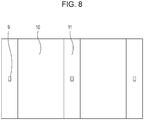
- the image forming unit 1 alternately forms an image portion 10 and a non-image portion 11 on the continuous sheet 7.
- a cutting mark 9 is printed on the non-image portion 11.
- the cutting mark 9 includes a record of cutting-position information for cutting by the cutting device.
- the cutting mark 9 serves as a reference for determining a cutting position.
- refreshing is performed by discharging ink, which is located near discharge ports of the discharge nozzles of the image forming unit 1 and has a high viscosity, on the non-image portion 11 at a predetermined time interval.
- a pattern for inspecting whether nozzles that discharge ink are capable of discharging ink or not, or a pattern for inspecting whether an image has a defect or not, is recorded at irregular timing.
- the non-image portion 11 may become long. Even in this case, the cutting mark 9 specifies the cutting position.
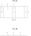
- Fig. 2A Ly is a length of the non-image portion 11.
- Fig. 2B is a schematic view from a side of the continuous sheet 7 shown in Fig. 2A .
- the image portion 10 is indicated by a solid line, and the non-image portion 11 is indicated by a broken line.
- the cutting mark 9 is provided on a side P of the broken line indicative of the non-image portion 11.
- the cutting device includes a first cutter 2 (first cutting means) provided downstream of the second main conveying roller pair 20, and a second cutter 3 (second cutting means) provided downstream of the first cutter 2.
- the first cutter 2 includes a movable blade 2m (first blade) and a fixed blade 2f (second blade).
- the continuous sheet 7 is cut when the movable blade 2m reciprocates in an up-down direction as shown in Fig. 5A .
- the second cutter 3 includes a movable blade 3m and a fixed blade 3f and has a configuration similar to the configuration of the first cutter 2.
- the fixed blade 2f is arranged at the upstream side in the conveyance direction, so in the direction 15 for the continuous sheet 7 (shown in Fig. 5A ), and the movable blade 2m is arranged at the downstream side in the conveyance direction.
- a printed surface of the continuous sheet 7 is the side P.
- the fixed blade 2f is constantly located closer to an image than the movable blade 2m, but the fixed blade 2f contacts a surface opposite the printed surface with an image.
- the movable blade 2m contacts the printed surface with an image, but the surface is the non-image portion 11.
- a movable blade position sensor (not shown) is provided and a movable blade actuator (cutter motor) is driven by a control means (see description of Fig. 3 below) in accordance with detection data of the movable blade position sensor.
- Control similar to the control for the first cutter 2 is provided for the second cutter 3 by the control means.
- First and second mark sensors 17 and 18 detect the cutting mark 9.
- the first cutter 2 includes the first mark sensor 17, and the second cutter 3 includes the second mark sensor 18.
- the first and second mark sensors 17 and 18 employ reflection-type sensors using photoelectric conversion. If the first and second mark sensors 17 and 18 detect the cutting mark 9, the continuous sheet 7 is conveyed by a predetermined distance and stopped. Then, the continuous sheet 7 is cut.
- a first conveying roller pair 4 (second conveying means) that conveys the continuous sheet 7 is arranged between the second main conveying roller pair 20 (first conveying means) and the first cutter 2.
- a second conveying roller pair 5 is arranged between the first cutter 2 and the second cutter 3.
- a third conveying roller pair 6 (third conveying means) is provided downstream of the second cutter 3.
- FIG. 3 is a control block diagram showing the image forming apparatus.
- a control circuit 300 (control means) includes a CPU 310, a ROM 311, and a RAM 312.
- the CPU 310 makes an instruction and a determination for control.
- the ROM 311 stores a program and a control table.
- the RAM 312 temporarily stores image information and control information.
- the control circuit 300 also includes drivers that drive various motors and heads.
- a first cutter motor 2a drives the first cutter 2.
- a second cutter motor 3a drives the second cutter 3.
- a first conveyance motor 4a drives a driving roller of the first conveying roller pair 4.
- a second conveyance motor 5a drives a driving roller of the second conveying roller pair 5.
- a third conveyance motor 6a drives a driving roller of the third conveying roller pair 6.
- Conveyance motor 19a drives the first main conveying roller pair 19 and the second main conveying roller pair 20.
- the continuous sheet 7 is conveyed to a cutting device shown in Fig. 5A at the printing conveyance speed Va.
- the first conveyance motor 4a, the second conveyance motor 5a, and the third conveyance motor 6a are driven.
- the first conveying roller pair 4 and the second conveying roller pair 5 convey the continuous sheet 7 in the direction 15 at the printing conveyance speed Va.
- Fig. 5A illustrates a state in which a leading edge of the continuous sheet 7 with an image formed by the image forming unit 1 passes through the first cutter 2 and a trailing edge of the non-image portion 11 reaches a position at which the first cutter 2 can cut the trailing edge. If the first mark sensor 17 detects the cutting mark 9 of the non-image portion 11 in step S2, the first conveyance motor 4a, the second conveyance motor 5a, and the third conveyance motor 6a are stopped after a predetermined time elapses in step S3.
- the first conveying roller pair 4 and the second conveying roller pair 5 thus convey the continuous sheet 7 by a predetermined distance (in the predetermined time), and then stop the continuous sheet 7 when the trailing edge of the non-image portion 11 reaches a cutting position 2c at which the first cutter 2 cuts the trailing edge.
- Fig. 5A illustrates a state in which the first conveying roller pair 4 and the second conveying roller pair 5 pinch the continuous sheet 7.
- the continuous sheet 7 may be occasionally pinched only by the first conveying roller pair 4, or by all the first to third conveying roller pairs 4 to 6 depending on the length in the conveying direction of the image portion 10.
- step S4 the first cutter motor 2a is driven to move the movable blade 2m of the first cutter 2 in the direction indicated by arrow A in Fig. 5B .
- the trailing edge in the conveyance direction of the non-image portion 11 (downstream end in the conveyance direction of a second image 10b) of the continuous sheet 7 is cut at the cutting position 2c.
- Fig. 5B illustrates a state in which the cutting by the first cutter 2 is ended.
- the movable blade 2m moves in the direction indicated by arrow B.
- a gap is provided between the movable blade 2m and the fixed blade 2f so that the continuous sheet 7 is conveyed through the gap.
- the first to third conveying roller pairs 4 to 6 are stopped.
- the image forming unit 1 continuously performs a continuous printing operation.
- a sag or bulge (loop) 7-A of the continuous sheet 7 is generated at a position located upstream the first conveying roller pair 4 in the conveyance direction as shown in Fig. 5B .
- the arrangement of this embodiment is provided to prevent an image from being degraded due to cracking of the printed surface or due to a scratch because a guide (not shown) for the continuous sheet 7 slides on the printed surface by the sag 7-A.
- Fig. 5C illustrates a state in which the sag 7-A of the continuous sheet 7 is being reduced.
- the second conveyance motor 5a and the third conveyance motor 6a are driven at high speeds in step S5.
- the second and third conveying roller pairs 5 and 6 start rotating, and convey a cut sheet 21, which has been cut from the continuous sheet 7, at a high conveyance speed Vh that is higher than the printing conveyance speed Va.
- a gap D is generated between the cut sheet 21 and the continuous sheet 7.
- the first conveyance motor 4a is driven at a high speed, starts rotating, and conveys the continuous sheet 7 at the high conveyance speed Vh in step S6.
- the first to third conveying roller pairs 4 to 6 convey the continuous sheet 7 at the high conveyance speed Vh that is higher than the printing conveyance speed Va of the image forming unit 1.
- a sag length (loop length) of the sag 7-A of the continuous sheet 7 is reduced. That is, the sag 7-A becomes a sag (loop) 7-B. If the gap D is not generated between the cut sheet 21 and the continuous sheet 7, the continuous sheet 7 may contact the cut sheet 21 before or after the cutting.
- the conveyance of the continuous sheet 7 is interrupted, and the continuous sheet 7 is obliquely conveyed. Thus, cutting accuracy may be degraded, and a scratch or the like may be generated due to sliding on the printed surface. As the result, an image may be degraded.
- step S7 the speeds of the first conveyance motor 4a and the second conveyance motor 5a are reduced such that the conveyance speed of the continuous sheet 7 becomes the printing conveyance speed Va. At this time, the cut sheet 21 is continuously conveyed at the high conveyance speed Vh.
- a cutting time required for cutting a sheet by the first and second cutters 2 and 3 is Tc (sec).
- the cutting time Tc is a time from when the gap is present between the movable blade 2m and the fixed blade 2f as shown in Fig. 5A until the movable blade 2m has (i) moved in the direction indicated by arrow A, (ii) cut the sheet, (iii) moved in the direction indicated by arrow B, and (iv) returned to the original position.
- the cutting time Tc is a fraction of a second.
- the output of driving means for example, a DC motor, for the movable blade may be increased.
- a current value, an inductance of a wire, and the size of the motor have to be increased to increase the output torque. If the current is increased with the unchanged inductance, the sectional area of the wire has to be increased. As the result, the size of the motor is increased. This may increase the cost, and the size of the entire apparatus. If the size of the motor is increased, acceleration performance of the motor is increased. However, rotational inertia of the motor is also increased, and hence a time may be required to stop the motor. Also, if the inductance (the number of turns) of the wire is increased, electric time constant is increased, and hence a speed at startup may be low.
- the continuous sheet 7 is conveyed at the printing conveyance speed Va in the image forming unit 1, and conveyed by the first conveying roller pair 4 at the high conveyance speed Vh.
- Time required for elimination of the maximum sag length of continuous sheet 7 maximum sag length of continuous sheet 7 / reduced length per unit time of sag length of continuous sheet 7 .
- Ly is a length of the non-image portion 11 of the continuous sheet 7.
- Lc is a distance between the cutting position 2c by the first cutter 2 and a cutting position 3c by the second cutter 3.
- a relationship among Vh (mm/sec), Tc (sec), Va (mm/sec), Ly (mm), and Lc (mm) for the first and second cutters 2 and 3 according to the embodiment of the present invention is as follows: Lc ⁇ Ly ⁇ Vh ⁇ Tc ⁇ Va / Vh ⁇ Va
- step S8 If the second mark sensor 18 detects the edge of the cutting mark 9 of the cut sheet 21, which has been cut and separated from the continuous sheet 7, in step S8, the third conveyance motor 6a is stopped after a predetermined time elapses in step S9.
- the third conveying roller 6 conveys the cut sheet 21 by a predetermined distance until the leading edge of the non-image portion 11 reaches the cutting position 3c by the second cutter 3.
- step S10 the second cutter motor 3a is driven, so that an upstream end in the conveyance direction of a first image 10c is cut by the second cutter 3 and hence the non-image portion 11 located upstream the trailing edge of the cut sheet 21 is cut and separated at the cutting position 3c.
- one the first and second cutters 2 and 3 cuts the upstream end in the conveyance direction of the image of the continuous sheet 7, and the other cuts the downstream end in the conveyance direction of the same image. Accordingly, the printout can be cut and separated from the continuous sheet 7.
- the cut sheet 21 pinched by the third conveying roller pair 6 slips relative to the third conveying roller pair 6. The accuracy of the cutting position is reduced.
- the following control is performed.
- the movable blade position sensor (not shown) detects the end of the reciprocal operation by the movable blade 2m of the first cutter 2 shown in Fig. 5B .
- a time required for the leading edge of the non-image portion 11 of the cut sheet 21, cut and separated from the continuous sheet 7 by the first cutter 2, to be conveyed to the cutting position 3c by the second cutter 3 at the high conveyance speed Vh after the trailing edge of the non-image portion 11 is cut, is as follows: Lc ⁇ Ly / Vh .
- Tc is the time required for the second cutter 3 to perform the cutting operation
- the required time from when the first cutter 2 ends (completes) cutting and separating the cut sheet 21 to when the second cutter 3 ends (completes) cutting the non-image portion 11 of the cut sheet 21, is as follows: Lc ⁇ Ly / Vh + Tc sec
- a distance of the conveyance at the reduced speed that is the printing conveyance speed Va after the sag is eliminated, is subtracted from the distance (Lc - Ly) of the conveyance until the continuous sheet 7 reaches the trailing edge of the cut sheet 21 as follows: Lc ⁇ Ly ⁇ Vh ⁇ Tc ⁇ Va / Vh ⁇ Va mm .
- continuous sheet reach time (3) + (8) is expressed as follows: Tc ⁇ Va / Vh ⁇ Va + Lc ⁇ Ly ⁇ Vh ⁇ Tc ⁇ Va / Vh ⁇ Va / Va
- the respective constants are determined to satisfy a relationship as follows: Cut sheet non-image portion cut end time (6) ⁇ continuous sheet reach time (8).
- the respective constants are determined by a condition as follows: Lc ⁇ Ly / Vh + Tc ⁇ Tc ⁇ Va / Vh ⁇ Va + Lc ⁇ Ly ⁇ Vh ⁇ Tc ⁇ Va / Vh ⁇ Va / Va
- Fig. 6B illustrates a state in which the non-image portion 11 is cut and separated from the cut sheet 21 by the second cutter 3 before the leading edge 10-a of the continuous sheet 7 reaches the trailing edge of the non-image portion 11 of the cut sheet 21.
- the second cutter 3 ends the cutting operation such that the movable blade 3m at the upstream side in the conveyance direction reciprocates in the directions indicated by arrows A and B in Fig. 6B .
- step S11 the third conveyance motor 6a is driven, so that the cut sheet 21 is conveyed to the downstream side.
- the conveyance speed at this time may be the high speed or the low speed depending on the state at the downstream side.
- Fig. 6A when the non-image portion 11 of the cut sheet 21 is cut, the next non-image portion 11 approaches the first cutter 2. The operation for cutting the next non-image portion 11 is repeatedly performed from step S1.
- the printed surface of the continuous sheet 7 is at the side P.
- the movable blade 3m first blade contacts the non-image portion 11 on the printed surface and the fixed blade 3f (second blade) contacts the back surface of the printed surface. Even if a dye component or a pigment component in ink on the printed surface adheres to the movable blade 3m, the movable blade 3m contacts the non-image portion 11 of the continuous sheet 7 during the next cutting. The image quality of an image surface is not degraded due to re-transferring from the movable blade 3m by such adhesion.
- the different first and second cutters perform the separation between the upstream end of the image portion 10 and the non-image portion 11 and the separation between the downstream end of the image portion 10 and the non-image portion 11. Also, the sheet is conveyed at the higher speed Vh between the cutters than the speed in the image forming unit 1. With this configuration, even if a sag is generated for the continuous sheet 7, the sag can be reduced immediately.
- the continuous sheet 7 has to be stopped at short intervals at the upstream and downstream positions of the non-image portion 11, which is a relatively short portion.
- the sag may be increased.
- the increase of the sag may cause a coating on a surface of the continuous sheet 7 to become cracked or scratched.
- the loop is not increased, and can be eliminated.
- the continuous sheet 7 has a thickness of 100 ⁇ m or larger and printing at a high speed with a high quality is desired. In this case, the continuous sheet 7 has to be stopped during cutting. In this embodiment, even if the continuous sheet 7 with the thickness of 100 ⁇ m is conveyed at a high speed Vh in the image forming unit 1, the continuous sheet can be stopped without difficulty.
- the printed state detection pattern for measuring the printed state of an image can be printed at irregular timing.
- the quality of a printout can be increased.
- the length of the non-image portion 11 can be optimized in accordance with a length of an image and a use amount of ink for the image. An optimal image can be obtained while an ink consumption in the non-image portion is minimized. Thus, the running cost can be decreased.
- the length of the non-image portion can be changed in accordance with an image size and a process factor such as the presence of a duty for an image (e.g. what the image is required for).
- the length of the non-image portion 11 can be optimized for every image (so is preferably minimized).
- the amount of wasted continuous sheet 7 and the amount of wasted ink can be minimized in accordance with the length of the non-image portion 11.
- the running cost for printing can be decreased.
- the blade of the first or second cutter 2 or 3 does not contact the image portion on the printed surface. Even if the apparatus is used for a long period, fine (good quality) images can be obtained.
- the image forming apparatus includes a first main conveying roller pair 19 that conveys in a conveyance direction a continuous sheet 7 fed from a continuous sheet feeding unit 8.
- An image forming unit 1 includes a plurality of recording heads that print an image on the continuous sheet 7 being conveyed in the conveyance direction.
- the image forming unit 1 forms images while forming a blank portion (non-image portion) between the images.
- a first conveying roller pair 41, a second conveying roller pair 51, and a third conveying roller pair 6 which convey the continuous sheet 7; a first mark sensor 17, a first cutter 2, and a second cutter 3 are provided downstream of the image forming unit 1.
- the position of the first cutter 2 and the position at which a sag of the continuous sheet 7 is formed are different from those of the first embodiment.
- the control block diagram in Fig. 3 can be referenced.
- the second embodiment will be described also with reference to Fig. 3 .
- the image forming unit 1 alternately forms an image portion 10 and a non-image portion 11 on the continuous sheet 7 as shown in Fig. 8 . Also, the image forming unit 1 prints a cutting mark 9 on the non-image portion 11.
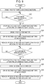
- step S21 a first conveyance motor 4a, a second conveyance motor 5a, and a third conveyance motor 6a are driven, so that the first conveying roller pair 41, the second conveying roller pair 51, and the third conveying roller pair 6 convey the continuous sheet 7 in a direction 15. If the first mark sensor 17 detects the cutting mark 9 in step S22, the second conveyance motor 5a and the third conveyance motor 6a are stopped after a predetermined time elapses in step S23.
- the continuous sheet 7 includes an image portion 13, a first non-image portion 12, and a second non-image portion 14. Referring to Fig. 10A , the continuous sheet 7 is stopped at a position at which a downstream end of the first non-image portion 12 can be cut by the first cutter 2.
- the second conveying roller pair 51 and the third conveying roller pair 6 stop the conveyance, in order to improve the perpendicularity of the cut surface of the sheet.
- another mark sensor (second mark sensor 18, not shown) may be provided upstream the second cutter 3 to increase conveyance accuracy.
- step S24 the first cutter motor 2a is driven, so that the first cutter 2 cuts the downstream end of the first non-image portion 12.
- a sag length (loop length) is equivalent to a conveyed distance by the first conveying roller pair 41 while the second conveying roller pair 51 is stopped during the cutting.
- step S25 the second conveyance motor 5a and the third conveyance motor 6a are driven at high speeds to eliminate the sag.
- the generated sag is eliminated when the second conveying roller pair 51 is rotated at a high speed after the cutting is ended.
- a conveyance speed Vh of the second conveying roller pair 51 at this time has to be at least a speed that allows the sag to be eliminated before the second non-image portion 14 reaches the first cutter 2.
- a distance by which the first conveying roller pair 41 conveys the second non-image portion 14 during the sag elimination time is as follows: Va Tc ⁇ Va / Vh ⁇ Va
- Expression 15 is the condition that allows the sag to be eliminated before the second non-image portion 14 reaches the first cutter 2.
- the third conveying roller pair 6 conveys the sheet at a rotation speed that is equal to or higher than a speed of the second conveying roller pair 51 that is eliminating the sag.
- step S27 If the second mark sensor 18 detects the cutting mark 9 in step S27, the second conveyance motor 5a and the third conveyance motor 6a are stopped after a predetermined time elapses in step S28.
- the continuous sheet 7 is conveyed to and stopped at a position as shown in Fig. 11A , the position at which the second cutter 3 can cut and separate the first non-image portion 12 from the image portion 13.
- step S29 the second cutter motor 3a is driven, so that the first non-image portion 12 is cut and separated from the image portion 13.
- Fig. 11B illustrates a sag (loop) generated during the above situation.
- the sag is generated at a position located upstream the second conveying roller pair 51 in the conveyance direction.
- a sag length (loop length) is equivalent to a conveyed distance by the first conveying roller pair 41 while the second conveying roller pair 51 is stopped during the cutting.
- a distance by which the first conveying roller pair 41 conveys the second non-image portion 14 during the sag elimination time is as follows: Va Tc ⁇ Va / Vh ⁇ Va
- a distance, by which the first conveying roller pair 41 conveys the second non-image portion 14 from the state shown in Fig. 11A to the formation of the sag is as follows: Tc ⁇ Va
- a distance by which the first conveying roller pair 41 conveys the second non-image portion 14 until the elimination of the sag is as follows: Va Tc ⁇ Va / Vh ⁇ Va
- Expression 23 is a condition that the second non-image portion 14 does not reach the cutting position at the first cutter 2 even if the first non-image portion 12 is cut from the state shown in Fig. 11A and the sag generated during the cutting is eliminated.
- the third conveying roller pair 6 conveys the sheet at a rotation speed that is equal to or higher than a speed of the second conveying roller pair 51 that is eliminating the sag.
- the speeds of the second conveying roller pair 51 and the third conveying roller pair 6 are reduced to a printing conveyance speed in step S31.
- step S23 the continuous sheet 7 is stopped at a position at which a downstream end of the second non-image portion 14 can be cut by the first cutter 2. Even during this stoppage, the image forming unit 1 continuously performs the printing, and the first conveying roller pair 41 continuously performs the conveyance.
- Fig. 12B illustrates a state in which the first cutter 2 cuts the second non-image portion 14. By cutting a leading edge of the second non-image portion 14, the cutting for the image portion 13 is ended, and hence only the image portion can be cut and obtained.
- Fig. 12B illustrates the same state as the state shown in Fig. 10B . The operation continues to the cutting for the next image portion 16.
- a conditional expression by which this embodiment is established is as follows: Tc ⁇ Va / Vh ⁇ Ly + cut length / Va and Cut length ⁇ Lc + Va 2 ⁇ Tc / Vh ⁇ Va
- Va is a conveyance speed by the first conveying roller pair 41
- Tc is a stop time of the second conveying roller pair 51 during the cutting
- Vh is a high conveyance speed of the second conveying roller pair 51 during the elimination of the sag
- Lc is a distance between the cutting position by the first cutter 2 and the cutting position by the second cutter 3
- Ly is a length of the non-image portion.
- the cut length is substantially equivalent to a length in the conveyance direction of the image portion 13. If a printout without a margin is formed, the cut length becomes smaller than the length of the image portion 13 in the conveyance direction. If a printout with margins is formed, the cut length becomes larger than the length of the image portion 13.
- Expression 24 is a condition that is satisfied by a next portion to be cut by the first cutter 2 after the sag generated during the cutting by the second cutter 3 is eliminated.
- Expression 25 is a condition for the cutting operation by the second cutter 3 after the sag generated by cutting by the first cutter 2 is eliminated.
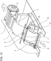
- Fig. 13 illustrates a configuration of an image forming apparatus according to the third example.
- Figs. 15A and 15B illustrate the details of an operation according to this example.
- the control block as illustrated in Fig. 3 , is used to implement the third example.
- the image forming apparatus includes a main conveying roller pair 22 that conveys in a conveyance direction a continuous sheet 7 fed from a continuous sheet feeding unit 8.
- An image forming unit 1 continuously prints images on the continuous sheet 7 by the main conveying roller pair 22 while forming a blank portion (non-image portion) between the images.
- a first conveying roller pair 4, a second conveying roller pair 5, and a third conveying roller pair 6, which convey the continuous sheet 7 from the image forming unit 1 to a cutting device, are provided downstream the image forming unit 1.
- a mark sensor 17 that detects a cutting mark in the non-image portion, and a first cutter 2 and a second cutter 3 are arranged.
- the second cutter 3 is movable along guide shafts 23 and 24 arranged in parallel to the conveyance direction.
- the distance between the first and second cutters 2 and 3 is adjustable in accordance with a desirable cut length.
- the adjustment is performed by a timing belt 25 and a motor 26.
- a cut length is equivalent to a length in the conveyance direction of the image portion 13.
- the cut length becomes shorter than the length in the conveyance direction of the image portion if the end of the image is trimmed, or larger than the length in the conveyance direction of the image portion if the image has a binding margin, depending on a formation mode of a printout.
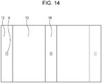
- the image forming unit 1 alternately forms on the continuous sheet 7 the image portion 13 with an image formed in accordance with image information, and first and second non-image portions 12 and 14 without an image.
- the image forming unit 1 also prints cutting marks 9 in the first and second non-image portions 12 and 14. If the mark sensor 17 detects the cutting mark 9, the continuous sheet 7 is fed by a predetermined length, located at predetermined positions, and cut by the first and second cutters 2 and 3. Thus, the image portion 13 is cut and separated.
- the second conveying roller pair 5 and the third conveying roller pair 6 stop the conveyance, in order to improve the perpendicularity of the cut surface of the sheet.
- Fig. 15A the continuous sheet 7 is conveyed in a direction 15.
- the motor 26 moves the second cutter 3. Accordingly, the distance between the cutting position by the first cutter 2 and the cutting position by the second cutter 3 can be changed. The distance between the cutting position by the first cutter 2 and the cutting position by the second cutter 3 is adjusted to be equivalent to the desirable cut length (the length of the image portion 13 in the conveyance direction).
- An exemplary arrangement of the image portion 13, the first non-image portion 12, and the second non-image portion 14 on the continuous sheet 7 is illustrated in Fig. 15A .
- a cutting method while the continuous sheet 7 is conveyed according to the third example will be described on the basis of the state illustrated in Fig. 15A .
- the continuous sheet 7 is stopped at a position at which the first non-image portion 12 located downstream of the image portion 13 can be cut and separated by the second cutter 3 and at which the second non-image portion 14 located upstream the image portion 13 can be cut and separated by the first cutter 2. While the second conveying roller pair 5 and the third conveying roller pair 6 are stopped, the image forming unit 1 continuously performs the printing, and the first conveying roller pair 4 continuously perform the conveyance.
- Fig. 15B illustrates a sag (loop) generated during the above situation.
- the sag is generated at a position located upstream of the second conveying roller pair 5.
- a sag length (loop length) is equivalent to a conveyed distance by the first conveying roller pair 4 while the second conveying roller pair 5 is stopped during the cutting.
- the generated sag is eliminated when the second conveying roller pair 5 is rotated at a high speed after the cutting is ended.
- a conveyance speed Vh of the second conveying roller pair 5 at this time has to be at least a speed that allows the sag to be eliminated before the third non-image portion 27 reaches the first cutter 2. This is provided as a conditional expression that establishes the third example.
- the third conveying roller pair 6 conveys the sheet at a rotation speed that is equal to or higher than a speed of the second conveying roller pair 5 that is eliminating the sag.
- the second embodiment may be combined with the third example.
- a conditional expression to which the second embodiment and third example are applicable is given below.
- a sag length (loop length) formed during the cutting is as follows: Tc ⁇ Va
- a distance, by which the first conveying roller pair 4 conveys the continuous sheet 7 from the state shown in Fig. 15A to the formation of the sag is as follows: Tc ⁇ Va
- a distance by which the first conveying roller pair 4 conveys the second non-image portion 14 until the elimination of the sag is as follows: Va Tc ⁇ Va / Vh ⁇ Va
- Va is a conveyance speed by the first conveying roller pair 4
- Tc is a stop time of the second conveying roller pair 5 during the cutting
- Vh is a high conveyance speed of the second conveying roller pair 5 during elimination of the sag
- Lc is a distance between the cutting position by the first cutter 2 and the cutting position by the second cutter 3
- Ly is a length of the non-image portion.
- Expression 31 is a condition that the third non-image portion 27 does not reach the cutting position at the first cutter 2 even if the image portion 13 is cut from the state shown in Fig. 15A and the sag generated during the cutting is eliminated.
- the cutting method according to the third example is effective because the cutting method can deal with a plurality of cut lengths as long as it satisfies conditions given below.
- Conditional expressions of this example is as follows: Cut length ⁇ Lc Vh ⁇ Va ⁇ cut length + Ly / Va ⁇ Va ⁇ Tc and Cut length ⁇ Lc + Va 2 ⁇ Tc / Vh ⁇ Va
- Expression 32, 33, and 34 are conditions that allow the sag to be continuously eliminated.
- the accuracy for the cut position can be increased irrespective of the accuracy for the conveyance of the continuous sheet 7. Also, an image with a small size can be cut.
Description
- The present invention relates to an image forming apparatus that continuously forms images on a continuous sheet and includes cutting means for cutting the continuous sheet in accordance with an image length, and to a cutting device.
- Japanese Patent Laid-Open No.
2003-211755 - With the printing apparatus disclosed in Japanese Patent Laid-Open No.
2003-211755 - Meanwhile, an inkjet recording apparatus has to discharge ink for refreshing on a non-image portion located between images in order to prevent ink located near an ink discharge portion from being dried. In addition, a pattern for inspecting whether nozzles are capable of discharging ink or not, or a pattern for detecting whether an image has a defect, has to be recorded at irregular timing. In the state in which the distance between images is fixed like Japanese Patent Laid-Open No.
2003-211755 - The present invention allows continuous high-speed printing to be performed even if conveyance of a continuous sheet is stopped while the continuous sheet is cut, and the present invention decreases a loop of the continuous sheet that is generated when the continuous sheet is cut.
- The present invention in its first aspect provides an image forming apparatus as specified in
claims - The present invention in its second aspect provides an image forming apparatus as specified in
claims 2 to 9. - The present invention in its third aspect provides a method as specified in
claim 10. - With the aspect of the present invention, the continuous high-speed printing can be performed even if the conveyance of the continuous sheet is stopped while the continuous sheet is cut. Also, the loop of the continuous sheet generated when the continuous sheet is cut can be reduced.
- Further features of the present invention will become apparent from the following description of exemplary embodiments with reference to the attached drawings.
-
-
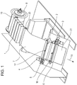
Fig. 1 is a perspective view showing the overview of an image forming apparatus including an image forming unit according to a first embodiment of the present invention. -
Figs. 2A and 2B each illustrate a printed state of an image, a non-image, and a cutting mark, which are printed by the image forming unit according to the first embodiment. -
Fig. 3 is a circuit block diagram of the image forming apparatus. -
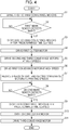
Fig. 4 is a flowchart showing an operation of the image forming apparatus. -
Figs. 5A to 5C are explanatory views showing an operation of a cutting device. -
Figs. 6A and 6B are explanatory views showing the operation of the cutting device. -
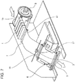
Fig. 7 is a perspective view showing the overview of an image forming apparatus including an image forming unit according to a second embodiment of the present invention. -
Fig. 8 illustrates a printed state of an image, a non-image, and a cutting mark, which are printed by the image forming unit according to the second embodiment. -
Fig. 9 is a flowchart showing an operation of the image forming apparatus according to the second embodiment. -
Figs. 10A and 10B are explanatory views each showing an operation of a cutting device according to the second embodiment. -
Figs. 11A and 11B are explanatory views each showing the operation of the cutting device according to the second embodiment. -
Figs. 12A and 12B are explanatory views each showing the operation of the cutting device according to the second embodiment. -
Fig. 13 is a perspective view showing the overview of an image forming apparatus including an image forming unit according to a third example. -
Fig. 14 illustrates a printed state of an image, a non-image, and a cutting mark, which are printed by the image forming unit according to the third example. -
Figs. 15A and 15B are explanatory views each showing an operation of a cutting device according to the third example. - An image forming apparatus according to a first embodiment of the present invention will be described below with reference to the attached drawings.
- Referring to
Fig. 1 , acontinuous sheet 7 fed from a continuoussheet feeding unit 8 is conveyed by a
first mainconveying roller pair 19 such that thecontinuous sheet 7 passes through an image forming unit (image forming means) 1 provided downstream the first mainconveying roller pair 19 in aconveyance direction 15. A second mainconveying roller pair 20 is provided downstream theimage forming unit 1. The second mainconveying roller pair 20 conveys thecontinuous sheet 7 from theimage forming unit 1 to a cutting device. - The
image forming unit 1 includes recording heads that discharge ink of respective colors and are arranged in the conveyance direction. The recording heads are arranged for cyan, magenta, yellow, and black. Each recording head has a plurality of discharge nozzles to cover an entire width of thecontinuous sheet 7 so that the recording head can discharge ink for the entire width of thecontinuous sheet 7. - The recording head discharges ink, in accordance with image information, on the
continuous sheet 7 that is continuously conveyed at a constant speed by the first mainconveying roller pair 19 and the second main conveying roller pair 20 (first conveying means), to successively form a plurality of images. Theimage forming unit 1 of the apparatus employs an inkjet recording method. Theimage forming unit 1 successively discharges ink of cyan, magenta, yellow, and black at a constant frequency without color misregistration. To obtain a fine (good quality) image, thecontinuous sheet 7 has to be conveyed at a constant printing conveyance speed Va. If the speed becomes lower than the printing conveyance speed Va, an image during image formation becomes a defective image. If the defective image is formed, thecontinuous sheet 7 during image formation has to be thrown away. This may increase running cost. In addition, printing has to be performed from the beginning again. This may reduce productivity. - A blank portion (non-image portion) is formed between images because ink is not discharged on that portion. Referring to
Fig. 2A , theimage forming unit 1 alternately forms animage portion 10 and anon-image portion 11 on thecontinuous sheet 7. Also, acutting mark 9 is printed on thenon-image portion 11. Thecutting mark 9 includes a record of cutting-position information for cutting by the cutting device. In this embodiment, thecutting mark 9 serves as a reference for determining a cutting position. Also, refreshing is performed by discharging ink, which is located near discharge ports of the discharge nozzles of theimage forming unit 1 and has a high viscosity, on thenon-image portion 11 at a predetermined time interval. Further, a pattern for inspecting whether nozzles that discharge ink are capable of discharging ink or not, or a pattern for inspecting whether an image has a defect or not, is recorded at irregular timing. When refreshing is performed or a pattern is recorded, thenon-image portion 11 may become long. Even in this case, the cuttingmark 9 specifies the cutting position. - In
Fig. 2A , Ly is a length of thenon-image portion 11.Fig. 2B is a schematic view from a side of thecontinuous sheet 7 shown inFig. 2A . Theimage portion 10 is indicated by a solid line, and thenon-image portion 11 is indicated by a broken line. The cuttingmark 9 is provided on a side P of the broken line indicative of thenon-image portion 11. - The cutting device includes a first cutter 2 (first cutting means) provided downstream of the second main conveying
roller pair 20, and a second cutter 3 (second cutting means) provided downstream of thefirst cutter 2. - The
first cutter 2 includes amovable blade 2m (first blade) and a fixedblade 2f (second blade). Thecontinuous sheet 7 is cut when themovable blade 2m reciprocates in an up-down direction as shown inFig. 5A . Thesecond cutter 3 includes amovable blade 3m and a fixedblade 3f and has a configuration similar to the configuration of thefirst cutter 2. When thecontinuous sheet 7 passes through thefist cutter 2, themovable blade 2m and the fixedblade 2f are separated from each other. In thefirst cutter 2, the fixedblade 2f is arranged at the upstream side in the conveyance direction, so in thedirection 15 for the continuous sheet 7 (shown inFig. 5A ), and themovable blade 2m is arranged at the downstream side in the conveyance direction. Referring toFig. 5A , a printed surface of thecontinuous sheet 7 is the side P. The fixedblade 2f is constantly located closer to an image than themovable blade 2m, but the fixedblade 2f contacts a surface opposite the printed surface with an image. Themovable blade 2m contacts the printed surface with an image, but the surface is thenon-image portion 11. - Hence, if the
first cutter 2 is continuously operated, a dye component or a pigment component contained in the ink on the printed surface that adheres to themovable blade 2m and is transferred again onto thecontinuous sheet 7 during next cutting, the dye component or the pigment component is transferred on thenon-image portion 11. The quality of an image on the printed surface is thus not degraded. - Preferably a movable blade position sensor (not shown) is provided and a movable blade actuator (cutter motor) is driven by a control means (see description of
Fig. 3 below) in accordance with detection data of the movable blade position sensor. Control similar to the control for thefirst cutter 2 is provided for thesecond cutter 3 by the control means. - First and
second mark sensors mark 9. Thefirst cutter 2 includes thefirst mark sensor 17, and thesecond cutter 3 includes thesecond mark sensor 18. The first andsecond mark sensors second mark sensors mark 9, thecontinuous sheet 7 is conveyed by a predetermined distance and stopped. Then, thecontinuous sheet 7 is cut. - A first conveying roller pair 4 (second conveying means) that conveys the
continuous sheet 7 is arranged between the second main conveying roller pair 20 (first conveying means) and thefirst cutter 2. A second conveyingroller pair 5 is arranged between thefirst cutter 2 and thesecond cutter 3. A third conveying roller pair 6 (third conveying means) is provided downstream of thesecond cutter 3. -
Fig. 3 is a control block diagram showing the image forming apparatus. A control circuit 300 (control means) includes aCPU 310, aROM 311, and aRAM 312. TheCPU 310 makes an instruction and a determination for control. TheROM 311 stores a program and a control table. TheRAM 312 temporarily stores image information and control information. Thecontrol circuit 300 also includes drivers that drive various motors and heads. - A
first cutter motor 2a drives thefirst cutter 2. Asecond cutter motor 3a drives thesecond cutter 3. Afirst conveyance motor 4a drives a driving roller of the first conveyingroller pair 4. Asecond conveyance motor 5a drives a driving roller of the second conveyingroller pair 5. Athird conveyance motor 6a drives a driving roller of the third conveyingroller pair 6.Conveyance motor 19a drives the first main conveyingroller pair 19 and the second main conveyingroller pair 20. - Next, the cutting operation according to the first embodiment of the present invention will be specifically described with reference to
Figs. 5A to 5C ,6A and 6B , and a flowchart inFig. 4 . Thecontinuous sheet 7 is conveyed to a cutting device shown inFig. 5A at the printing conveyance speed Va. In step S1 inFig. 4 , thefirst conveyance motor 4a, thesecond conveyance motor 5a, and thethird conveyance motor 6a are driven. In the cutting device, the first conveyingroller pair 4 and the second conveyingroller pair 5 convey thecontinuous sheet 7 in thedirection 15 at the printing conveyance speed Va. -
Fig. 5A illustrates a state in which a leading edge of thecontinuous sheet 7 with an image formed by theimage forming unit 1 passes through thefirst cutter 2 and a trailing edge of thenon-image portion 11 reaches a position at which thefirst cutter 2 can cut the trailing edge. If thefirst mark sensor 17 detects the cuttingmark 9 of thenon-image portion 11 in step S2, thefirst conveyance motor 4a, thesecond conveyance motor 5a, and thethird conveyance motor 6a are stopped after a predetermined time elapses in step S3. The first conveyingroller pair 4 and the second conveyingroller pair 5 thus convey thecontinuous sheet 7 by a predetermined distance (in the predetermined time), and then stop thecontinuous sheet 7 when the trailing edge of thenon-image portion 11 reaches acutting position 2c at which thefirst cutter 2 cuts the trailing edge.Fig. 5A illustrates a state in which the first conveyingroller pair 4 and the second conveyingroller pair 5 pinch thecontinuous sheet 7. Thecontinuous sheet 7 may be occasionally pinched only by the first conveyingroller pair 4, or by all the first to third conveyingroller pairs 4 to 6 depending on the length in the conveying direction of theimage portion 10. - In step S4, the
first cutter motor 2a is driven to move themovable blade 2m of thefirst cutter 2 in the direction indicated by arrow A inFig. 5B . The trailing edge in the conveyance direction of the non-image portion 11 (downstream end in the conveyance direction of asecond image 10b) of thecontinuous sheet 7 is cut at thecutting position 2c.Fig. 5B illustrates a state in which the cutting by thefirst cutter 2 is ended. When the cutting is ended, themovable blade 2m moves in the direction indicated by arrow B. Hence, a gap is provided between themovable blade 2m and the fixedblade 2f so that thecontinuous sheet 7 is conveyed through the gap. During this period, the first to third conveyingroller pairs 4 to 6 are stopped. While the first to third conveyingroller pairs 4 to 6 are stopped, theimage forming unit 1 continuously performs a continuous printing operation. Thus, a sag or bulge (loop) 7-A of thecontinuous sheet 7 is generated at a position located upstream the first conveyingroller pair 4 in the conveyance direction as shown inFig. 5B . - Even if the sag 7-A is generated, the arrangement of this embodiment is provided to prevent an image from being degraded due to cracking of the printed surface or due to a scratch because a guide (not shown) for the
continuous sheet 7 slides on the printed surface by the sag 7-A. -
Fig. 5C illustrates a state in which the sag 7-A of thecontinuous sheet 7 is being reduced. When the gap is provided between themovable blade 2m and the fixedblade 2f after the cutting operation is ended, thesecond conveyance motor 5a and thethird conveyance motor 6a are driven at high speeds in step S5. The second and third conveying roller pairs 5 and 6 start rotating, and convey acut sheet 21, which has been cut from thecontinuous sheet 7, at a high conveyance speed Vh that is higher than the printing conveyance speed Va. Thus, a gap D is generated between thecut sheet 21 and thecontinuous sheet 7. Then, thefirst conveyance motor 4a is driven at a high speed, starts rotating, and conveys thecontinuous sheet 7 at the high conveyance speed Vh in step S6. - The first to third conveying
roller pairs 4 to 6 convey thecontinuous sheet 7 at the high conveyance speed Vh that is higher than the printing conveyance speed Va of theimage forming unit 1. A sag length (loop length) of the sag 7-A of thecontinuous sheet 7 is reduced. That is, the sag 7-A becomes a sag (loop) 7-B. If the gap D is not generated between thecut sheet 21 and thecontinuous sheet 7, thecontinuous sheet 7 may contact thecut sheet 21 before or after the cutting. The conveyance of thecontinuous sheet 7 is interrupted, and thecontinuous sheet 7 is obliquely conveyed. Thus, cutting accuracy may be degraded, and a scratch or the like may be generated due to sliding on the printed surface. As the result, an image may be degraded. - If the sag 7-B of the
continuous sheet 7 is eliminated as shown inFig. 6A , in step S7, the speeds of thefirst conveyance motor 4a and thesecond conveyance motor 5a are reduced such that the conveyance speed of thecontinuous sheet 7 becomes the printing conveyance speed Va. At this time, thecut sheet 21 is continuously conveyed at the high conveyance speed Vh. - In this embodiment, a cutting time required for cutting a sheet by the first and
second cutters movable blade 2m and the fixedblade 2f as shown inFig. 5A until themovable blade 2m has (i) moved in the direction indicated by arrow A, (ii) cut the sheet, (iii) moved in the direction indicated by arrow B, and (iv) returned to the original position. The shorter the cutting time Tc (sec) is, the smaller the sag length of thecontinuous sheet 7 formed during the cutting. In this embodiment, the cutting time Tc is a fraction of a second. To further reduce the cutting time, the output of driving means, for example, a DC motor, for the movable blade may be increased. However, a current value, an inductance of a wire, and the size of the motor have to be increased to increase the output torque. If the current is increased with the unchanged inductance, the sectional area of the wire has to be increased. As the result, the size of the motor is increased. This may increase the cost, and the size of the entire apparatus. If the size of the motor is increased, acceleration performance of the motor is increased. However, rotational inertia of the motor is also increased, and hence a time may be required to stop the motor. Also, if the inductance (the number of turns) of the wire is increased, electric time constant is increased, and hence a speed at startup may be low. - During the cutting for the
continuous sheet 7, the first conveyingroller pair 4 is stopped, and theimage forming unit 1 provided upstream the first conveyingroller pair 4 conveys thecontinuous sheet 7 at the printing conveyance speed Va. A maximum sag length of thecontinuous sheet 7 is as follows:
- After the cutting, the
continuous sheet 7 is conveyed at the printing conveyance speed Va in theimage forming unit 1, and conveyed by the first conveyingroller pair 4 at the high conveyance speed Vh. A reduced length per unit time of the sag length of thecontinuous sheet 7 is as follows:
- Here, a time required for elimination of the maximum sag length is theoretically obtained as follows:

- By using
Expressions 
- Further, using
Expression 3, a conveyed distance of a leading edge 10-a of thecontinuous sheet 7 after the leading edge 10-a is cut by thefirst cutter 2 before the maximum sag length of thecontinuous sheet 7 is eliminated is as follows:
- By using
Expression 3, the above expression is rewritten as follows:
- In
Fig. 6A , Ly is a length of thenon-image portion 11 of thecontinuous sheet 7. Lc is a distance between the cuttingposition 2c by thefirst cutter 2 and acutting position 3c by thesecond cutter 3. - Thus, a distance by which the leading edge of the
non-image portion 11 of thecut sheet 21 cut from thecontinuous sheet 7 by thefirst cutter 2 is conveyed until the leading edge is cut by thesecond cutter 3 as shown inFig. 6A is obtained as follows:
- A relationship among Vh (mm/sec), Tc (sec), Va (mm/sec), Ly (mm), and Lc (mm) for the first and
second cutters 
- Since the relationship by
Expression 5 is established, the sag of thecontinuous sheet 7 generated by thefirst cutter 2 can be eliminated by a single cycle of the cutting operation. Hence, even when a plurality of cycles of the cutting operation are performed, the maximum sag length of thecontinuous sheet 7 is not increased through accumulation. - If the
second mark sensor 18 detects the edge of the cuttingmark 9 of thecut sheet 21, which has been cut and separated from thecontinuous sheet 7, in step S8, thethird conveyance motor 6a is stopped after a predetermined time elapses in step S9. The third conveyingroller 6 conveys thecut sheet 21 by a predetermined distance until the leading edge of thenon-image portion 11 reaches thecutting position 3c by thesecond cutter 3. In step S10, thesecond cutter motor 3a is driven, so that an upstream end in the conveyance direction of afirst image 10c is cut by thesecond cutter 3 and hence thenon-image portion 11 located upstream the trailing edge of thecut sheet 21 is cut and separated at thecutting position 3c. As described above, one the first andsecond cutters continuous sheet 7, and the other cuts the downstream end in the conveyance direction of the same image. Accordingly, the printout can be cut and separated from thecontinuous sheet 7. - If the leading edge 10-a of the
continuous sheet 7 approaches and reaches thenon-image portion 11 during the cutting, thecut sheet 21 pinched by the third conveyingroller pair 6 slips relative to the third conveyingroller pair 6. The accuracy of the cutting position is reduced. To prevent the leading edge 10-a of thecontinuous sheet 7 from reaching thenon-image portion 11 during the cutting until thenon-image portion 11 of thecut sheet 21 is cut by thesecond cutter 3, the following control is performed. - The movable blade position sensor (not shown) detects the end of the reciprocal operation by the
movable blade 2m of thefirst cutter 2 shown inFig. 5B . - First, a time required for the leading edge of the
non-image portion 11 of thecut sheet 21, cut and separated from thecontinuous sheet 7 by thefirst cutter 2, to be conveyed to thecutting position 3c by thesecond cutter 3 at the high conveyance speed Vh after the trailing edge of thenon-image portion 11 is cut, is as follows:
- Next, since Tc is the time required for the
second cutter 3 to perform the cutting operation, the required time from when thefirst cutter 2 ends (completes) cutting and separating thecut sheet 21 to when thesecond cutter 3 ends (completes) cutting thenon-image portion 11 of thecut sheet 21, is as follows:
- Then, a time required for the
cut sheet 21 to be cut and separated by thefirst cutter 2, and for the leading edge of theimage portion 10 of thecontinuous sheet 7, remaining at the upstream side, to be conveyed at the high conveyance speed Vh is obtained byExpression 3 as described above. Thus, a distance of the conveyance at the high conveyance speed Vh is calculated as follows:
- A distance of the conveyance at the reduced speed, that is the printing conveyance speed Va after the sag is eliminated, is subtracted from the distance (Lc - Ly) of the conveyance until the
continuous sheet 7 reaches the trailing edge of thecut sheet 21 as follows:
- Hence, a time for the conveyance at the printing conveyance speed Va after the sag of the
continuous sheet 7 is eliminated, because of the conveyance at the high conveyance speed Vh, is as follows:
- Using the above expressions, continuous sheet reach time = (3) + (8) is expressed as follows:

- In this embodiment of the present invention, the respective constants are determined to satisfy a relationship as follows:
Cut sheet non-image portion cut end time (6) ≤ continuous sheet reach time (8). - In particular, the respective constants are determined by a condition as follows:

-
Fig. 6B illustrates a state in which thenon-image portion 11 is cut and separated from thecut sheet 21 by thesecond cutter 3 before the leading edge 10-a of thecontinuous sheet 7 reaches the trailing edge of thenon-image portion 11 of thecut sheet 21. Similarly to thefirst cutter 2, thesecond cutter 3 ends the cutting operation such that themovable blade 3m at the upstream side in the conveyance direction reciprocates in the directions indicated by arrows A and B inFig. 6B . - In step S11, the
third conveyance motor 6a is driven, so that thecut sheet 21 is conveyed to the downstream side. The conveyance speed at this time may be the high speed or the low speed depending on the state at the downstream side. Referring toFig. 6A , when thenon-image portion 11 of thecut sheet 21 is cut, the nextnon-image portion 11 approaches thefirst cutter 2. The operation for cutting the nextnon-image portion 11 is repeatedly performed from step S1. - The printed surface of the
continuous sheet 7 is at the side P. Thus, themovable blade 3m (first blade) contacts thenon-image portion 11 on the printed surface and the fixedblade 3f (second blade) contacts the back surface of the printed surface. Even if a dye component or a pigment component in ink on the printed surface adheres to themovable blade 3m, themovable blade 3m contacts thenon-image portion 11 of thecontinuous sheet 7 during the next cutting. The image quality of an image surface is not degraded due to re-transferring from themovable blade 3m by such adhesion. - In this embodiment, the different first and second cutters perform the separation between the upstream end of the
image portion 10 and thenon-image portion 11 and the separation between the downstream end of theimage portion 10 and thenon-image portion 11. Also, the sheet is conveyed at the higher speed Vh between the cutters than the speed in theimage forming unit 1. With this configuration, even if a sag is generated for thecontinuous sheet 7, the sag can be reduced immediately. - If a single cutter performs the cutting for the continuous sheet in which the
image portion 10 and thenon-image portion 11 are alternately arranged, thecontinuous sheet 7 has to be stopped at short intervals at the upstream and downstream positions of thenon-image portion 11, which is a relatively short portion. Hence, the sag may be increased. The increase of the sag may cause a coating on a surface of thecontinuous sheet 7 to become cracked or scratched. In contrast, with this embodiment, the loop is not increased, and can be eliminated. - In particular, if a photo printing apparatus is used, the
continuous sheet 7 has a thickness of 100 µm or larger and printing at a high speed with a high quality is desired. In this case, thecontinuous sheet 7 has to be stopped during cutting. In this embodiment, even if thecontinuous sheet 7 with the thickness of 100 µm is conveyed at a high speed Vh in theimage forming unit 1, the continuous sheet can be stopped without difficulty. - Also, since the length in the conveyance direction of the
non-image portion 11 can be changed depending on an image, the printed state detection pattern for measuring the printed state of an image can be printed at irregular timing. Thus, the quality of a printout can be increased. - The length of the
non-image portion 11 can be optimized in accordance with a length of an image and a use amount of ink for the image. An optimal image can be obtained while an ink consumption in the non-image portion is minimized. Thus, the running cost can be decreased. - The length of the non-image portion can be changed in accordance with an image size and a process factor such as the presence of a duty for an image (e.g. what the image is required for). Thus, the length of the
non-image portion 11 can be optimized for every image (so is preferably minimized). As the result, the amount of wastedcontinuous sheet 7 and the amount of wasted ink can be minimized in accordance with the length of thenon-image portion 11. The running cost for printing can be decreased. - In addition, the blade of the first or
second cutter - An image forming apparatus according to a second embodiment of the present invention will be described below with reference to the attached drawings.
- Referring to
Fig. 7 , the image forming apparatus includes a first main conveyingroller pair 19 that conveys in a conveyance direction acontinuous sheet 7 fed from a continuoussheet feeding unit 8. Animage forming unit 1 includes a plurality of recording heads that print an image on thecontinuous sheet 7 being conveyed in the conveyance direction. Theimage forming unit 1 forms images while forming a blank portion (non-image portion) between the images. A first conveyingroller pair 41, a second conveyingroller pair 51, and a third conveyingroller pair 6 which convey thecontinuous sheet 7; afirst mark sensor 17, afirst cutter 2, and asecond cutter 3 are provided downstream of theimage forming unit 1. - In the second embodiment, the position of the
first cutter 2 and the position at which a sag of thecontinuous sheet 7 is formed are different from those of the first embodiment. However, the control block diagram inFig. 3 can be referenced. Hence, the second embodiment will be described also with reference toFig. 3 . - The
image forming unit 1 alternately forms animage portion 10 and anon-image portion 11 on thecontinuous sheet 7 as shown inFig. 8 . Also, theimage forming unit 1 prints a cuttingmark 9 on thenon-image portion 11. - An operation of the image forming apparatus will be described below with reference to a flowchart in
Fig. 9 , as well asFigs. 10A and 10B ,11A and11B , and12A and 12B . In step S21, afirst conveyance motor 4a, asecond conveyance motor 5a, and athird conveyance motor 6a are driven, so that the first conveyingroller pair 41, the second conveyingroller pair 51, and the third conveyingroller pair 6 convey thecontinuous sheet 7 in adirection 15. If thefirst mark sensor 17 detects the cuttingmark 9 in step S22, thesecond conveyance motor 5a and thethird conveyance motor 6a are stopped after a predetermined time elapses in step S23. Consequently the second conveyingroller pair 51 and the third conveyingroller pair 6 feed thecontinuous sheet 7 by a predetermined length, and then are stopped. Referring toFig. 10A , thecontinuous sheet 7 includes animage portion 13, a firstnon-image portion 12, and a secondnon-image portion 14. Referring toFig. 10A , thecontinuous sheet 7 is stopped at a position at which a downstream end of the firstnon-image portion 12 can be cut by thefirst cutter 2. - At this time, the second conveying
roller pair 51 and the third conveyingroller pair 6 stop the conveyance, in order to improve the perpendicularity of the cut surface of the sheet. With regard to a conveyance error between the second conveyingroller pair 51 and the third conveyingroller pair 6, another mark sensor (second mark sensor 18, not shown) may be provided upstream thesecond cutter 3 to increase conveyance accuracy. - In step S24, the
first cutter motor 2a is driven, so that thefirst cutter 2 cuts the downstream end of the firstnon-image portion 12. - While the second conveying
roller pair 51 and the third conveyingroller pair 6 are stopped, theimage forming unit 1 continuously performs printing, and the first conveyingroller pair 41 continuously performs conveyance. Then, a sag (loop of sheet) is formed between the first conveyingroller pair 41 and the second conveyingroller pair 51 as shown inFig. 10B . A sag length (loop length) is equivalent to a conveyed distance by the first conveyingroller pair 41 while the second conveyingroller pair 51 is stopped during the cutting. In particular, the sag length is as follows:
- When the cutting is ended, in step S25, the
second conveyance motor 5a and thethird conveyance motor 6a are driven at high speeds to eliminate the sag. The generated sag is eliminated when the second conveyingroller pair 51 is rotated at a high speed after the cutting is ended. A conveyance speed Vh of the second conveyingroller pair 51 at this time has to be at least a speed that allows the sag to be eliminated before the secondnon-image portion 14 reaches thefirst cutter 2. A time required for elimination of the sag is as follows:
- A distance by which the first conveying
roller pair 41 conveys the secondnon-image portion 14 during the sag elimination time is as follows:
- In the state shown in
Fig. 10A , the downstream end of the secondnon-image portion 14 is located upstream a cutting position by thefirst cutter 2 by a distance as follows:
- Hence, a condition is as follows:

-
Expression 15 is the condition that allows the sag to be eliminated before the secondnon-image portion 14 reaches thefirst cutter 2. - Also, after the cutting, the third conveying
roller pair 6 conveys the sheet at a rotation speed that is equal to or higher than a speed of the second conveyingroller pair 51 that is eliminating the sag. - When the sag is eliminated, the speeds of the second conveying
roller pair 51 and the third conveyingroller pair 6 are reduced to a printing conveyance speed in step S26. - If the
second mark sensor 18 detects the cuttingmark 9 in step S27, thesecond conveyance motor 5a and thethird conveyance motor 6a are stopped after a predetermined time elapses in step S28. Thecontinuous sheet 7 is conveyed to and stopped at a position as shown inFig. 11A , the position at which thesecond cutter 3 can cut and separate the firstnon-image portion 12 from theimage portion 13. In step S29, thesecond cutter motor 3a is driven, so that the firstnon-image portion 12 is cut and separated from theimage portion 13. - While the second conveying
roller pair 51 and the third conveyingroller pair 6 are stopped, theimage forming unit 1 continuously performs the printing, and the first conveyingroller pair 41 continuously perform the conveyance.Fig. 11B illustrates a sag (loop) generated during the above situation. The sag is generated at a position located upstream the second conveyingroller pair 51 in the conveyance direction. A sag length (loop length) is equivalent to a conveyed distance by the first conveyingroller pair 41 while the second conveyingroller pair 51 is stopped during the cutting. In particular, the sag length is as follows:
- The generated sag is eliminated when the second conveying
roller pair 51 and the third conveyingroller pair 6 are rotated at high speeds in step S30 after the cutting is ended. A conveyance speed Vh of the second conveyingroller pair 51 at this time has to be at least a speed that allows the sag to be eliminated before the secondnon-image portion 14 reaches thefirst cutter 2. That is, a speed that allows the sag to be reduced is as follows:
- A time required for elimination of the sag is as follows:

- A distance by which the first conveying
roller pair 41 conveys the secondnon-image portion 14 during the sag elimination time is as follows:
- A distance, by which the first conveying
roller pair 41 conveys the secondnon-image portion 14 from the state shown inFig. 11A to the formation of the sag is as follows:
- A distance by which the first conveying
roller pair 41 conveys the secondnon-image portion 14 until the elimination of the sag is as follows:
- In the state shown in
Fig. 11A , the downstream end of the secondnon-image portion 14 is provided upstream the cutting position by thefirst cutter 2 by a distance as follows:
- Hence, a relationship is as follows:

- Expression 23 is a condition that the second
non-image portion 14 does not reach the cutting position at thefirst cutter 2 even if the firstnon-image portion 12 is cut from the state shown inFig. 11A and the sag generated during the cutting is eliminated. - This is provided as a conditional expression that establishes the second embodiment. Also, after the cutting, the third conveying
roller pair 6 conveys the sheet at a rotation speed that is equal to or higher than a speed of the second conveyingroller pair 51 that is eliminating the sag. When the sag is eliminated, the speeds of the second conveyingroller pair 51 and the third conveyingroller pair 6 are reduced to a printing conveyance speed in step S31. - Then, the operation goes back to step S21, and the
first mark sensor 17 detects the mark on the secondnon-image portion 14 in step S22. Referring toFig. 12A , in step S23, thecontinuous sheet 7 is stopped at a position at which a downstream end of the secondnon-image portion 14 can be cut by thefirst cutter 2. Even during this stoppage, theimage forming unit 1 continuously performs the printing, and the first conveyingroller pair 41 continuously performs the conveyance. -
Fig. 12B illustrates a state in which thefirst cutter 2 cuts the secondnon-image portion 14. By cutting a leading edge of the secondnon-image portion 14, the cutting for theimage portion 13 is ended, and hence only the image portion can be cut and obtained.Fig. 12B illustrates the same state as the state shown inFig. 10B . The operation continues to the cutting for thenext image portion 16. - A conditional expression by which this embodiment is established is as follows:


roller pair 41, Tc is a stop time of the second conveyingroller pair 51 during the cutting, Vh is a high conveyance speed of the second conveyingroller pair 51 during the elimination of the sag, Lc is a distance between the cutting position by thefirst cutter 2 and the cutting position by thesecond cutter 3, and Ly is a length of the non-image portion. With the cut length in addition to the above values, the inequality is provided. The cut length is substantially equivalent to a length in the conveyance direction of theimage portion 13. If a printout without a margin is formed, the cut length becomes smaller than the length of theimage portion 13 in the conveyance direction. If a printout with margins is formed, the cut length becomes larger than the length of theimage portion 13. - Here,
Expression 24 is a condition that is satisfied by a next portion to be cut by thefirst cutter 2 after the sag generated during the cutting by thesecond cutter 3 is eliminated. Also,Expression 25 is a condition for the cutting operation by thesecond cutter 3 after the sag generated by cutting by thefirst cutter 2 is eliminated. - The following description of the third example is illustrative only and not embodying the claimed invention.
Fig. 13 illustrates a configuration of an image forming apparatus according to the third example.Figs. 15A and 15B illustrate the details of an operation according to this example. The control block, as illustrated inFig. 3 , is used to implement the third example. - Referring to
Fig. 13 , the image forming apparatus includes a main conveyingroller pair 22 that conveys in a conveyance direction acontinuous sheet 7 fed from a continuoussheet feeding unit 8. Animage forming unit 1 continuously prints images on thecontinuous sheet 7 by the main conveyingroller pair 22 while forming a blank portion (non-image portion) between the images. A first conveyingroller pair 4, a second conveyingroller pair 5, and a third conveyingroller pair 6, which convey thecontinuous sheet 7 from theimage forming unit 1 to a cutting device, are provided downstream theimage forming unit 1. Also, amark sensor 17 that detects a cutting mark in the non-image portion, and afirst cutter 2 and asecond cutter 3 are arranged. Thesecond cutter 3 is movable alongguide shafts 23 and 24 arranged in parallel to the conveyance direction. The distance between the first andsecond cutters timing belt 25 and amotor 26. In the following description, it is expected that a cut length is equivalent to a length in the conveyance direction of theimage portion 13. However, the cut length becomes shorter than the length in the conveyance direction of the image portion if the end of the image is trimmed, or larger than the length in the conveyance direction of the image portion if the image has a binding margin, depending on a formation mode of a printout. - Referring to
Fig. 14 , theimage forming unit 1 alternately forms on thecontinuous sheet 7 theimage portion 13 with an image formed in accordance with image information, and first and secondnon-image portions image forming unit 1 also prints cuttingmarks 9 in the first and secondnon-image portions mark sensor 17 detects the cuttingmark 9, thecontinuous sheet 7 is fed by a predetermined length, located at predetermined positions, and cut by the first andsecond cutters image portion 13 is cut and separated. At this time, the second conveyingroller pair 5 and the third conveyingroller pair 6 stop the conveyance, in order to improve the perpendicularity of the cut surface of the sheet. - Next, an operation of the third example will be described below with reference to
Figs. 15A and 15B . - In
Fig. 15A , thecontinuous sheet 7 is conveyed in adirection 15. Themotor 26 moves thesecond cutter 3. Accordingly, the distance between the cutting position by thefirst cutter 2 and the cutting position by thesecond cutter 3 can be changed. The distance between the cutting position by thefirst cutter 2 and the cutting position by thesecond cutter 3 is adjusted to be equivalent to the desirable cut length (the length of theimage portion 13 in the conveyance direction). An exemplary arrangement of theimage portion 13, the firstnon-image portion 12, and the secondnon-image portion 14 on thecontinuous sheet 7 is illustrated inFig. 15A . A cutting method while thecontinuous sheet 7 is conveyed according to the third example will be described on the basis of the state illustrated inFig. 15A . - Referring to
Fig. 15A , thecontinuous sheet 7 is stopped at a position at which the firstnon-image portion 12 located downstream of theimage portion 13 can be cut and separated by thesecond cutter 3 and at which the secondnon-image portion 14 located upstream theimage portion 13 can be cut and separated by thefirst cutter 2. While the second conveyingroller pair 5 and the third conveyingroller pair 6 are stopped, theimage forming unit 1 continuously performs the printing, and the first conveyingroller pair 4 continuously perform the conveyance. - While the second conveying
roller pair 5 and the third conveyingroller pair 6 are stopped, thefirst cutter 2 and thesecond cutter 3 simultaneously perform the cutting, so that the firstnon-image portion 12 and the secondnon-image portion 14 are separated from theimage portion 13.Fig. 15B illustrates a sag (loop) generated during the above situation. - The sag is generated at a position located upstream of the second conveying
roller pair 5. A sag length (loop length) is equivalent to a conveyed distance by the first conveyingroller pair 4 while the second conveyingroller pair 5 is stopped during the cutting. The generated sag is eliminated when the second conveyingroller pair 5 is rotated at a high speed after the cutting is ended. A conveyance speed Vh of the second conveyingroller pair 5 at this time has to be at least a speed that allows the sag to be eliminated before the thirdnon-image portion 27 reaches thefirst cutter 2. This is provided as a conditional expression that establishes the third example. Also, after the cutting, the third conveyingroller pair 6 conveys the sheet at a rotation speed that is equal to or higher than a speed of the second conveyingroller pair 5 that is eliminating the sag. - The second embodiment may be combined with the third example. A conditional expression to which the second embodiment and third example are applicable is given below. A sag length (loop length) formed during the cutting is as follows:

- A time required for elimination of the sag is as follows:

- A distance, by which the first conveying
roller pair 4 conveys thecontinuous sheet 7 from the state shown inFig. 15A to the formation of the sag is as follows:
- A distance by which the first conveying
roller pair 4 conveys the secondnon-image portion 14 until the elimination of the sag is as follows:
- In the state shown in
Fig. 15B , the downstream end of a thirdnon-image portion 27 is provided upstream of the cutting position by thefirst cutter 2 by a distance as follows:
- Hence, a relationship is as follows:

- In the above expressions, Va is a conveyance speed by the first conveying
roller pair 4, Tc is a stop time of the second conveyingroller pair 5 during the cutting, Vh is a high conveyance speed of the second conveyingroller pair 5 during elimination of the sag, Lc is a distance between the cutting position by thefirst cutter 2 and the cutting position by thesecond cutter 3, and Ly is a length of the non-image portion. - Expression 31 is a condition that the third
non-image portion 27 does not reach the cutting position at thefirst cutter 2 even if theimage portion 13 is cut from the state shown inFig. 15A and the sag generated during the cutting is eliminated. - If the desirable cut length meets Expressions 30 and 31, the cutting method according to the third example is effective because the cutting method can deal with a plurality of cut lengths as long as it satisfies conditions given below.
- Conditional expressions of this example is as follows:


- Here, Expression 32, 33, and 34 are conditions that allow the sag to be continuously eliminated.
- With this example, since the relative positions between the
first cutter 2 and thesecond cutter 3 are accurately determined, the accuracy for the cut position can be increased irrespective of the accuracy for the conveyance of thecontinuous sheet 7. Also, an image with a small size can be cut. - While the present invention has been described with reference to exemplary embodiments, it is to be understood that the invention is not limited to the disclosed exemplary embodiments. The scope of the following claims is to be accorded the broadest interpretation so as to encompass all such modifications and equivalent structures and functions.
- This application is a divisional application of European patent application no.
11155602.3 EP-A-2361737 . The original claims of the parent application are repeated below in the present specification and form part of the content of this divisional application as filed. -
- 1. A cutting device comprising:
- first conveying means (20,4) arranged to continuously convey a continuous sheet (7) having images formed thereon;
- second conveying means (4,5) provided downstream of the first conveying means (4) in a conveyance direction and arranged to convey the continuous sheet (7);
- first cutting means (2) provided downstream of the second conveying means (5) in the conveyance direction and arranged to cut the continuous sheet (7);
- second cutting means (3) provided downstream of the first cutting means (2) in the conveyance direction and arranged to cut the continuous sheet (7); and
- control means arranged to perform control such that one of the first cutting means (2) and the second cutting means (3) is arranged to cut an upstream end in the conveyance direction of an image on the continuous sheet (7), the other is arranged to cut a downstream end in the conveyance direction of the same image, the second conveying means (4,5) is arranged to stop during the cutting by the first cutting means (2), to form a loop of the continuous sheet (7) at a position between the first conveying means (4) and the second conveying means (5), and then once the cutting is ended, the second conveying means (4,5) is arranged to convey the continuous sheet (7) at a higher conveyance speed than a conveyance speed by the first conveying means (4) to reduce the loop.
- 2. An image forming apparatus comprising:
image forming means (1) arranged to continuously form images on a continuous sheet (7) and a cutting device according toclaim 1. - 3. The image forming apparatus according to
claim 2, wherein the first cutting means (2) is arranged to cut the upstream end in the conveyance direction of the image on the continuous sheet (7), and the second cutting means (3) is arranged to cut the downstream end in the conveyance direction of the same image. - 4. The image forming apparatus according to
claim - 5. The image forming apparatus according to
claim 4, further comprising a mark sensor (17, 18) arranged to detect a mark (9) that is recorded by the image forming unit (1), at a position between the first and second images, the mark being indicative of positional information for the cutting by the first or second cutting means (2, 3). - 6. The image forming apparatus according to
claim
wherein the image forming apparatus satisfies expressions as follows,

- 7. The image forming apparatus according to
claim - 8. The image forming apparatus according to
claim 7, wherein a distance between the first cutting means (2) and the second cutting means (3) can be changed in accordance with an image size. - 9. The image forming apparatus according to
claim
wherein the image forming apparatus satisfies an expression as follows,
- 10. The image forming apparatus according to any one of
claims 2 to 9, wherein the image forming means (1) is arranged to perform recording by discharging ink. - 11. The image forming apparatus according to any one of
claims 2 to 10, wherein the continuous sheet (7) has a thickness of 100 µm or larger. - 12. The image forming apparatus according to any one of
claims 2 to 6,
wherein the first or second cutting means (2, 3) includes a first blade (2m, 3m) that contacts a surface of the continuous sheet (7) with an image formed thereon and a second blade (2f, 3f) that contacts a surface of the continuous sheet (7) without an image, and
wherein when the first blade (2m, 3m) engages with the second blade (2f, 3f), the second blade (2f, 3f) is located closer to the image than the first blade (2m, 3m).
Claims (10)
- An image forming apparatus which includes an image forming unit (1) configured to sequentially form a first image (10) and a second image (10) on a continuous sheet (7) and which cuts out a non-image portion (11) located between a first portion on which the first image is formed and a second portion on which the second image is formed to create a first printout on which the first image is formed and a second printout on which the second image is formed, the image forming apparatus comprising, downstream the image forming unit (1) in a conveyance direction of the continuous sheet (7) and in turn, a first conveying means (20) configured to convey the continuous sheet, a second conveying means (4) configured to convey the continuous sheet, a first cutting means (2) configured to cut the continuous sheet and a second cutting means (3) configured to cut the continuous sheet, characterized in that the image forming apparatus further comprises a control means (300) configured to cause the second conveying means (4) to stop while causing the first conveying means (20) to convey the continuous sheet at a first conveyance speed (Va) so as to form a loop of the continuous sheet and cause the first cutting means (2) to cut an end portion, being on a side of the second portion, of the non-image portion (11), and subsequently cause the second conveying means (4) to convey the continuous sheet at a second conveyance speed (Vh) higher than the first conveyance speed (Va) so as to decrease the loop of the continuous sheet and cause the second cutting means (3) to cut an end portion, being on a side of the first portion, of the non-image portion (11).
- An image forming apparatus which includes an image forming unit (1) configured to sequentially form a first image (10) and a second image (10) on a continuous sheet (7) and which cuts out a non-image portion (11) located between a first portion on which the first image is formed and a second portion on which the second image is formed to create a first printout on which the first image is formed and a second printout on which the second image is formed, the image forming apparatus comprising, downstream the image forming unit in a conveyance direction of the continuous sheet and in turn, a first conveying means (41) configured to convey the continuous sheet, a second conveying means (51) configured to convey the continuous sheet (7), a first cutting means (2) configured to cut the continuous sheet and a second cutting means (3) configured to cut the continuous sheet, characterized in that the image forming apparatus further comprises a control means (300) configured to cause the second conveying means (51) to stop while causing the first conveying means (41) to convey the continuous sheet at a first conveyance speed (Va) so as to form a loop of the continuous sheet and cause the first cutting means (2) to cut an end portion, being on a side of the first portion, of the non-image portion (11), and subsequently cause the second conveying means (51) to convey the continuous sheet at a second conveyance speed (Vh) higher than the first conveyance speed (Va) so as to decrease the loop of the continuous sheet and cause the second cutting means (3) to cut an end portion, being on a side of the second portion, of the non-image portion (11).
- The image forming apparatus according to claim 1 or 2, wherein the first cutting means (2) and the second cutting means (3) are arranged in a manner such that a distance (Lc) between a cutting position of the first cutting means (2) and a cutting position of the second cutting means (3) is longer than a length (Ly) of the non-image portion (11) in the conveyance direction.
- The image forming apparatus according to claim 3, wherein the image forming apparatus satisfies the following expression,

- The image forming apparatus according to any one of claims 1 to 4, wherein the first cutting means (2) includes a first movable blade (2m) on a side of a surface of the continuous sheet (7) on which the image is formed by the image forming unit (1) and a first fixed blade (2f) arranged upstream the first movable blade (2m) in the conveyance direction and provided on a reverse side of the surface of the continuous sheet (7), and the second cutting means (3) includes a second movable blade (3m) provided on the side of the surface of the continuous sheet (7) on which the image is formed and a second fixed blade (3f) arranged downstream the second movable blade (3m) in the conveyance direction and provided on the reverse side of the surface.
- The image forming apparatus according to any one of claims 1 to 5, wherein a mark (9) used for cutting the continuous sheet (7) by the first cutting means (2) or the second cutting means (3) is printed on the non-image portion (11), and wherein the image forming apparatus further comprises a mark detection sensor (17, 18) configured to detect the mark (9).
- The image forming apparatus according to any one of claims 1 to 6, wherein the image forming unit (1) includes a recording head provided with a plurality of nozzles for discharging ink, the plurality of nozzles being arranged facing the continuous sheet so as to cover an entire width of the continuous sheet (7).
- The image forming apparatus according to claim 7, wherein the continuous sheet (7) is conveyed at the first conveyance speed (Va) when the recording head performs a recording operation.
- The image forming apparatus according to any one of claim 1 to 8, wherein the continuous sheet (7) has a thickness of 100 µm or larger.
- A method of creating a first printout and a second printout by an image forming apparatus which comprises, downstream an image forming unit (1) in a conveyance direction of a continuous sheet (7) and in turn, a first conveying means (20) configured to convey the continuous sheet, a second conveying means (4) configured to convey the continuous sheet, a first cutting means (2) configured to cut the continuous sheet and a second cutting means (3) configured to cut the continuous sheet, and which sequentially forms, using the image forming unit, a first image and a second image on the continuous sheet (7) and cuts out a non-image portion (11) located between a first portion on which the first image is formed and a second portion on which the second image is formed, the method comprising, in sequence:forming the first image (10) and the second image (10) sequentially on the continuous sheet (7) by the image forming unit (1);characterized in that the method further comprises:stopping the second conveying means (4) while conveying the continuous sheet at a first conveyance speed (Va) by the first conveying means (20) so as to form a loop of the continuous sheet and cutting an end portion, being on a side of the second portion, of the non-image portion (11) by the first cutting means (2);conveying, by the second conveying means (4), the continuous sheet at a second conveyance speed (Vh) higher than the first conveyance speed (Va) so as to decrease the loop of the continuous sheet (7); andcutting an end portion, being on a side of the first portion, of the non-image portion by the second cutting means (3).
Applications Claiming Priority (2)
| Application Number | Priority Date | Filing Date | Title |
|---|---|---|---|
| JP2010041662A JP5213892B2 (en) | 2010-02-26 | 2010-02-26 | Image forming apparatus and cutting apparatus |
| EP11155602.3A EP2361737B1 (en) | 2010-02-26 | 2011-02-23 | Image forming apparatus and cutting device |
Related Parent Applications (1)
| Application Number | Title | Priority Date | Filing Date |
|---|---|---|---|
| EP11155602.3A Division EP2361737B1 (en) | 2010-02-26 | 2011-02-23 | Image forming apparatus and cutting device |
Publications (2)
| Publication Number | Publication Date |
|---|---|
| EP2700483A1 EP2700483A1 (en) | 2014-02-26 |
| EP2700483B1 true EP2700483B1 (en) | 2019-09-04 |
Family
ID=44121435
Family Applications (2)
| Application Number | Title | Priority Date | Filing Date |
|---|---|---|---|
| EP13172332.2A Active EP2700483B1 (en) | 2010-02-26 | 2011-02-23 | Image forming apparatus and cutting device |
| EP11155602.3A Active EP2361737B1 (en) | 2010-02-26 | 2011-02-23 | Image forming apparatus and cutting device |
Family Applications After (1)
| Application Number | Title | Priority Date | Filing Date |
|---|---|---|---|
| EP11155602.3A Active EP2361737B1 (en) | 2010-02-26 | 2011-02-23 | Image forming apparatus and cutting device |
Country Status (4)
| Country | Link |
|---|---|
| US (1) | US9289914B2 (en) |
| EP (2) | EP2700483B1 (en) |
| JP (1) | JP5213892B2 (en) |
| CN (1) | CN102189829B (en) |
Families Citing this family (18)
| Publication number | Priority date | Publication date | Assignee | Title |
|---|---|---|---|---|
| US20110211899A1 (en) * | 2010-02-26 | 2011-09-01 | Canon Kabushiki Kaisha | Print control method and print apparatus |
| JP5372037B2 (en) * | 2011-02-01 | 2013-12-18 | キヤノン株式会社 | Printing method and printing apparatus |
| JP6039172B2 (en) * | 2011-10-21 | 2016-12-07 | キヤノン株式会社 | Sheet cutting device and printer |
| JP2014172280A (en) * | 2013-03-08 | 2014-09-22 | Ricoh Co Ltd | Image formation device |
| JP6150595B2 (en) * | 2013-04-16 | 2017-06-21 | キヤノン株式会社 | Printing apparatus and printing method |
| JP5967383B2 (en) * | 2014-03-18 | 2016-08-10 | コニカミノルタ株式会社 | Post-processing apparatus and image forming system |
| JP6312043B2 (en) * | 2014-05-23 | 2018-04-18 | 富士ゼロックス株式会社 | Image forming apparatus, cutting processing apparatus, printing system, and program |
| CN104444541B (en) * | 2015-01-09 | 2017-07-28 | 京东方光科技有限公司 | A kind of belt cutting device |
| CN104589809A (en) * | 2015-02-08 | 2015-05-06 | 李丽容 | Automatic paper cutting component of note printer |
| DE102015213544A1 (en) * | 2015-07-17 | 2017-01-19 | Cewe Stiftung & Co. Kgaa | Device for generating stickers |
| WO2017013779A1 (en) * | 2015-07-23 | 2017-01-26 | ホリゾン・インターナショナル株式会社 | Sheet cutting device |
| CN106476070A (en) * | 2015-11-25 | 2017-03-08 | 衡阳唯美印务有限公司 | A kind of automatic paper cutting machine |
| JP6458724B2 (en) * | 2015-12-25 | 2019-01-30 | ブラザー工業株式会社 | Printing device |
| CN106219303B (en) * | 2016-07-29 | 2017-08-25 | 广州市程翔机械有限公司 | Adhesive tape detects severing and discharge system |
| CN106241475B (en) * | 2016-08-31 | 2018-11-20 | 上海良劲自动化科技有限公司 | Track fixed length cutting system |
| JP6990400B2 (en) * | 2017-10-02 | 2022-02-03 | デュプロ精工株式会社 | Strip cutting device |
| JP7427941B2 (en) | 2019-12-04 | 2024-02-06 | コニカミノルタ株式会社 | Image forming device and program |
| JP7457570B2 (en) * | 2020-05-14 | 2024-03-28 | キヤノン株式会社 | Recording apparatus and transport control method thereof |
Family Cites Families (13)
| Publication number | Priority date | Publication date | Assignee | Title |
|---|---|---|---|---|
| JPS60137765A (en) | 1983-12-26 | 1985-07-22 | Kawasaki Steel Corp | Trailing end cut control method in coil shearing line |
| JPS60137765U (en) * | 1984-02-20 | 1985-09-12 | 株式会社東芝 | elevator indicator |
| JPH07304220A (en) * | 1994-05-12 | 1995-11-21 | Hitachi Ltd | Printer device |
| JP3688433B2 (en) * | 1997-06-13 | 2005-08-31 | 三菱電機株式会社 | Printing device |
| FI105463B (en) * | 1999-01-22 | 2000-08-31 | Valmet Corp | Method and apparatus for winding a paper web |
| JP2001105383A (en) * | 1999-10-05 | 2001-04-17 | Fuji Photo Film Co Ltd | Sheet cutting device |
| JP2001310849A (en) * | 2000-04-28 | 2001-11-06 | Konica Corp | Image recording device |
| JP2003054044A (en) * | 2001-08-21 | 2003-02-26 | Fuji Photo Film Co Ltd | Image recorder |
| JP2003211755A (en) | 2002-01-25 | 2003-07-29 | Seiko Epson Corp | Printer, printing system and printer driver |
| JP4406923B2 (en) * | 2004-03-10 | 2010-02-03 | ブラザー工業株式会社 | Label making device |
| EP1908597B8 (en) | 2005-07-27 | 2012-08-08 | Mitsubishi Electric Corporation | Printing device and printing method |
| JP2009233915A (en) * | 2008-03-26 | 2009-10-15 | Sato Knowledge & Intellectual Property Institute | Printer with cutter |
| JP2010155388A (en) * | 2008-12-26 | 2010-07-15 | Olympus Corp | Image recorder and method for controlling the same |
-
2010
- 2010-02-26 JP JP2010041662A patent/JP5213892B2/en active Active
- 2010-12-10 US US12/965,724 patent/US9289914B2/en active Active
-
2011
- 2011-02-22 CN CN201110042049.XA patent/CN102189829B/en active Active
- 2011-02-23 EP EP13172332.2A patent/EP2700483B1/en active Active
- 2011-02-23 EP EP11155602.3A patent/EP2361737B1/en active Active
Non-Patent Citations (1)
| Title |
|---|
| None * |
Also Published As
| Publication number | Publication date |
|---|---|
| JP2011177909A (en) | 2011-09-15 |
| EP2361737B1 (en) | 2013-12-11 |
| US20110211900A1 (en) | 2011-09-01 |
| EP2700483A1 (en) | 2014-02-26 |
| JP5213892B2 (en) | 2013-06-19 |
| EP2361737A1 (en) | 2011-08-31 |
| CN102189829B (en) | 2016-07-06 |
| CN102189829A (en) | 2011-09-21 |
| US9289914B2 (en) | 2016-03-22 |
Similar Documents
| Publication | Publication Date | Title |
|---|---|---|
| EP2700483B1 (en) | Image forming apparatus and cutting device | |
| US9132674B2 (en) | Printer and control method of a printer | |
| US9896298B2 (en) | Apparatus and method for cutting sheet | |
| US7607661B2 (en) | Control device, conveyance control device, conveyance system and image forming system | |
| CN101905569B (en) | Printing apparatus | |
| US7367732B2 (en) | Method and apparatus for controlling the sheet feeding speed in a printer | |
| CN106965552B (en) | Printing method and printing apparatus | |
| US20120204693A1 (en) | Recording medium cutting apparatus | |
| US20120051824A1 (en) | Printing apparatus | |
| US8767224B2 (en) | Recording device and recording and cutting control method | |
| US8459766B2 (en) | Print apparatus and control method thereof | |
| US8408828B2 (en) | Image recording apparatus | |
| US20040141021A1 (en) | Image recording apparatus and image recording method | |
| US11912019B2 (en) | Printing apparatus | |
| US20210229475A1 (en) | Liquid discharge apparatus | |
| JP3941683B2 (en) | Print medium conveyance control apparatus, serial type printing apparatus, print medium conveyance control apparatus, and print medium conveyance control method in serial printing apparatus | |
| JP2007007967A (en) | Cutting device and image forming apparatus having the same | |
| CN114803585A (en) | Printing apparatus and control method of printing apparatus | |
| JPH09295721A (en) | Sheet feeding device and image forming device | |
| JP2017136689A (en) | Printer and correction method for ink landing position | |
| JP4466636B2 (en) | Print medium conveyance control apparatus, serial printing apparatus, and print medium conveyance control method in printing apparatus | |
| JP2008229979A (en) | Printing method and printing device using the printing method | |
| JP4428377B2 (en) | Print medium conveyance control apparatus and serial type printing apparatus in printing apparatus | |
| JP2005014496A (en) | Material to be recorded, recording device, and recording position setting method for material to be recorded | |
| JP2019181844A (en) | Recording device and its control method |
Legal Events
| Date | Code | Title | Description |
|---|---|---|---|
| PUAI | Public reference made under article 153(3) epc to a published international application that has entered the european phase |
Free format text: ORIGINAL CODE: 0009012 |
|
| AC | Divisional application: reference to earlier application |
Ref document number: 2361737 Country of ref document: EP Kind code of ref document: P |
|
| AK | Designated contracting states |
Kind code of ref document: A1 Designated state(s): AL AT BE BG CH CY CZ DE DK EE ES FI FR GB GR HR HU IE IS IT LI LT LU LV MC MK MT NL NO PL PT RO RS SE SI SK SM TR |
|
| 17P | Request for examination filed |
Effective date: 20140826 |
|
| RBV | Designated contracting states (corrected) |
Designated state(s): AL AT BE BG CH CY CZ DE DK EE ES FI FR GB GR HR HU IE IS IT LI LT LU LV MC MK MT NL NO PL PT RO RS SE SI SK SM TR |
|
| STAA | Information on the status of an ep patent application or granted ep patent |
Free format text: STATUS: EXAMINATION IS IN PROGRESS |
|
| 17Q | First examination report despatched |
Effective date: 20180626 |
|
| GRAP | Despatch of communication of intention to grant a patent |
Free format text: ORIGINAL CODE: EPIDOSNIGR1 |
|
| STAA | Information on the status of an ep patent application or granted ep patent |
Free format text: STATUS: GRANT OF PATENT IS INTENDED |
|
| INTG | Intention to grant announced |
Effective date: 20190412 |
|
| GRAS | Grant fee paid |
Free format text: ORIGINAL CODE: EPIDOSNIGR3 |
|
| GRAA | (expected) grant |
Free format text: ORIGINAL CODE: 0009210 |
|
| STAA | Information on the status of an ep patent application or granted ep patent |
Free format text: STATUS: THE PATENT HAS BEEN GRANTED |
|
| AC | Divisional application: reference to earlier application |
Ref document number: 2361737 Country of ref document: EP Kind code of ref document: P |
|
| AK | Designated contracting states |
Kind code of ref document: B1 Designated state(s): AL AT BE BG CH CY CZ DE DK EE ES FI FR GB GR HR HU IE IS IT LI LT LU LV MC MK MT NL NO PL PT RO RS SE SI SK SM TR |
|
| REG | Reference to a national code |
Ref country code: GB Ref legal event code: FG4D |
|
| REG | Reference to a national code |
Ref country code: CH Ref legal event code: EP |
|
| REG | Reference to a national code |
Ref country code: AT Ref legal event code: REF Ref document number: 1174730 Country of ref document: AT Kind code of ref document: T Effective date: 20190915 |
|
| REG | Reference to a national code |
Ref country code: DE Ref legal event code: R096 Ref document number: 602011061901 Country of ref document: DE |
|
| REG | Reference to a national code |
Ref country code: IE Ref legal event code: FG4D |
|
| REG | Reference to a national code |
Ref country code: NL Ref legal event code: MP Effective date: 20190904 |
|
| REG | Reference to a national code |
Ref country code: LT Ref legal event code: MG4D |
|
| PG25 | Lapsed in a contracting state [announced via postgrant information from national office to epo] |
Ref country code: BG Free format text: LAPSE BECAUSE OF FAILURE TO SUBMIT A TRANSLATION OF THE DESCRIPTION OR TO PAY THE FEE WITHIN THE PRESCRIBED TIME-LIMIT Effective date: 20191204 Ref country code: SE Free format text: LAPSE BECAUSE OF FAILURE TO SUBMIT A TRANSLATION OF THE DESCRIPTION OR TO PAY THE FEE WITHIN THE PRESCRIBED TIME-LIMIT Effective date: 20190904 Ref country code: NO Free format text: LAPSE BECAUSE OF FAILURE TO SUBMIT A TRANSLATION OF THE DESCRIPTION OR TO PAY THE FEE WITHIN THE PRESCRIBED TIME-LIMIT Effective date: 20191204 Ref country code: HR Free format text: LAPSE BECAUSE OF FAILURE TO SUBMIT A TRANSLATION OF THE DESCRIPTION OR TO PAY THE FEE WITHIN THE PRESCRIBED TIME-LIMIT Effective date: 20190904 Ref country code: LT Free format text: LAPSE BECAUSE OF FAILURE TO SUBMIT A TRANSLATION OF THE DESCRIPTION OR TO PAY THE FEE WITHIN THE PRESCRIBED TIME-LIMIT Effective date: 20190904 Ref country code: FI Free format text: LAPSE BECAUSE OF FAILURE TO SUBMIT A TRANSLATION OF THE DESCRIPTION OR TO PAY THE FEE WITHIN THE PRESCRIBED TIME-LIMIT Effective date: 20190904 |
|
| PG25 | Lapsed in a contracting state [announced via postgrant information from national office to epo] |
Ref country code: RS Free format text: LAPSE BECAUSE OF FAILURE TO SUBMIT A TRANSLATION OF THE DESCRIPTION OR TO PAY THE FEE WITHIN THE PRESCRIBED TIME-LIMIT Effective date: 20190904 Ref country code: ES Free format text: LAPSE BECAUSE OF FAILURE TO SUBMIT A TRANSLATION OF THE DESCRIPTION OR TO PAY THE FEE WITHIN THE PRESCRIBED TIME-LIMIT Effective date: 20190904 Ref country code: GR Free format text: LAPSE BECAUSE OF FAILURE TO SUBMIT A TRANSLATION OF THE DESCRIPTION OR TO PAY THE FEE WITHIN THE PRESCRIBED TIME-LIMIT Effective date: 20191205 Ref country code: AL Free format text: LAPSE BECAUSE OF FAILURE TO SUBMIT A TRANSLATION OF THE DESCRIPTION OR TO PAY THE FEE WITHIN THE PRESCRIBED TIME-LIMIT Effective date: 20190904 Ref country code: LV Free format text: LAPSE BECAUSE OF FAILURE TO SUBMIT A TRANSLATION OF THE DESCRIPTION OR TO PAY THE FEE WITHIN THE PRESCRIBED TIME-LIMIT Effective date: 20190904 |
|
| REG | Reference to a national code |
Ref country code: AT Ref legal event code: MK05 Ref document number: 1174730 Country of ref document: AT Kind code of ref document: T Effective date: 20190904 |
|
| PG25 | Lapsed in a contracting state [announced via postgrant information from national office to epo] |
Ref country code: PT Free format text: LAPSE BECAUSE OF FAILURE TO SUBMIT A TRANSLATION OF THE DESCRIPTION OR TO PAY THE FEE WITHIN THE PRESCRIBED TIME-LIMIT Effective date: 20200106 Ref country code: NL Free format text: LAPSE BECAUSE OF FAILURE TO SUBMIT A TRANSLATION OF THE DESCRIPTION OR TO PAY THE FEE WITHIN THE PRESCRIBED TIME-LIMIT Effective date: 20190904 Ref country code: AT Free format text: LAPSE BECAUSE OF FAILURE TO SUBMIT A TRANSLATION OF THE DESCRIPTION OR TO PAY THE FEE WITHIN THE PRESCRIBED TIME-LIMIT Effective date: 20190904 Ref country code: EE Free format text: LAPSE BECAUSE OF FAILURE TO SUBMIT A TRANSLATION OF THE DESCRIPTION OR TO PAY THE FEE WITHIN THE PRESCRIBED TIME-LIMIT Effective date: 20190904 Ref country code: IT Free format text: LAPSE BECAUSE OF FAILURE TO SUBMIT A TRANSLATION OF THE DESCRIPTION OR TO PAY THE FEE WITHIN THE PRESCRIBED TIME-LIMIT Effective date: 20190904 Ref country code: RO Free format text: LAPSE BECAUSE OF FAILURE TO SUBMIT A TRANSLATION OF THE DESCRIPTION OR TO PAY THE FEE WITHIN THE PRESCRIBED TIME-LIMIT Effective date: 20190904 Ref country code: PL Free format text: LAPSE BECAUSE OF FAILURE TO SUBMIT A TRANSLATION OF THE DESCRIPTION OR TO PAY THE FEE WITHIN THE PRESCRIBED TIME-LIMIT Effective date: 20190904 |
|
| PG25 | Lapsed in a contracting state [announced via postgrant information from national office to epo] |
Ref country code: IS Free format text: LAPSE BECAUSE OF FAILURE TO SUBMIT A TRANSLATION OF THE DESCRIPTION OR TO PAY THE FEE WITHIN THE PRESCRIBED TIME-LIMIT Effective date: 20200224 Ref country code: SK Free format text: LAPSE BECAUSE OF FAILURE TO SUBMIT A TRANSLATION OF THE DESCRIPTION OR TO PAY THE FEE WITHIN THE PRESCRIBED TIME-LIMIT Effective date: 20190904 Ref country code: CZ Free format text: LAPSE BECAUSE OF FAILURE TO SUBMIT A TRANSLATION OF THE DESCRIPTION OR TO PAY THE FEE WITHIN THE PRESCRIBED TIME-LIMIT Effective date: 20190904 Ref country code: SM Free format text: LAPSE BECAUSE OF FAILURE TO SUBMIT A TRANSLATION OF THE DESCRIPTION OR TO PAY THE FEE WITHIN THE PRESCRIBED TIME-LIMIT Effective date: 20190904 |
|
| REG | Reference to a national code |
Ref country code: DE Ref legal event code: R097 Ref document number: 602011061901 Country of ref document: DE |
|
| PLBE | No opposition filed within time limit |
Free format text: ORIGINAL CODE: 0009261 |
|
| STAA | Information on the status of an ep patent application or granted ep patent |
Free format text: STATUS: NO OPPOSITION FILED WITHIN TIME LIMIT |
|
| PG2D | Information on lapse in contracting state deleted |
Ref country code: IS |
|
| PG25 | Lapsed in a contracting state [announced via postgrant information from national office to epo] |
Ref country code: DK Free format text: LAPSE BECAUSE OF FAILURE TO SUBMIT A TRANSLATION OF THE DESCRIPTION OR TO PAY THE FEE WITHIN THE PRESCRIBED TIME-LIMIT Effective date: 20190904 Ref country code: IS Free format text: LAPSE BECAUSE OF FAILURE TO SUBMIT A TRANSLATION OF THE DESCRIPTION OR TO PAY THE FEE WITHIN THE PRESCRIBED TIME-LIMIT Effective date: 20200105 |
|
| 26N | No opposition filed |
Effective date: 20200605 |
|
| PG25 | Lapsed in a contracting state [announced via postgrant information from national office to epo] |
Ref country code: SI Free format text: LAPSE BECAUSE OF FAILURE TO SUBMIT A TRANSLATION OF THE DESCRIPTION OR TO PAY THE FEE WITHIN THE PRESCRIBED TIME-LIMIT Effective date: 20190904 |
|
| REG | Reference to a national code |
Ref country code: CH Ref legal event code: PL |
|
| REG | Reference to a national code |
Ref country code: BE Ref legal event code: MM Effective date: 20200229 |
|
| PG25 | Lapsed in a contracting state [announced via postgrant information from national office to epo] |
Ref country code: LU Free format text: LAPSE BECAUSE OF NON-PAYMENT OF DUE FEES Effective date: 20200223 Ref country code: MC Free format text: LAPSE BECAUSE OF FAILURE TO SUBMIT A TRANSLATION OF THE DESCRIPTION OR TO PAY THE FEE WITHIN THE PRESCRIBED TIME-LIMIT Effective date: 20190904 |
|
| PG25 | Lapsed in a contracting state [announced via postgrant information from national office to epo] |
Ref country code: CH Free format text: LAPSE BECAUSE OF NON-PAYMENT OF DUE FEES Effective date: 20200229 Ref country code: LI Free format text: LAPSE BECAUSE OF NON-PAYMENT OF DUE FEES Effective date: 20200229 |
|
| PG25 | Lapsed in a contracting state [announced via postgrant information from national office to epo] |
Ref country code: IE Free format text: LAPSE BECAUSE OF NON-PAYMENT OF DUE FEES Effective date: 20200223 |
|
| PG25 | Lapsed in a contracting state [announced via postgrant information from national office to epo] |
Ref country code: BE Free format text: LAPSE BECAUSE OF NON-PAYMENT OF DUE FEES Effective date: 20200229 |
|
| PG25 | Lapsed in a contracting state [announced via postgrant information from national office to epo] |
Ref country code: TR Free format text: LAPSE BECAUSE OF FAILURE TO SUBMIT A TRANSLATION OF THE DESCRIPTION OR TO PAY THE FEE WITHIN THE PRESCRIBED TIME-LIMIT Effective date: 20190904 Ref country code: MT Free format text: LAPSE BECAUSE OF FAILURE TO SUBMIT A TRANSLATION OF THE DESCRIPTION OR TO PAY THE FEE WITHIN THE PRESCRIBED TIME-LIMIT Effective date: 20190904 Ref country code: CY Free format text: LAPSE BECAUSE OF FAILURE TO SUBMIT A TRANSLATION OF THE DESCRIPTION OR TO PAY THE FEE WITHIN THE PRESCRIBED TIME-LIMIT Effective date: 20190904 |
|
| PG25 | Lapsed in a contracting state [announced via postgrant information from national office to epo] |
Ref country code: MK Free format text: LAPSE BECAUSE OF FAILURE TO SUBMIT A TRANSLATION OF THE DESCRIPTION OR TO PAY THE FEE WITHIN THE PRESCRIBED TIME-LIMIT Effective date: 20190904 |
|
| PGFP | Annual fee paid to national office [announced via postgrant information from national office to epo] |
Ref country code: FR Payment date: 20230119 Year of fee payment: 13 |
|
| PGFP | Annual fee paid to national office [announced via postgrant information from national office to epo] |
Ref country code: GB Payment date: 20230121 Year of fee payment: 13 Ref country code: DE Payment date: 20230119 Year of fee payment: 13 |