EP2698625A1 - Vorrichtung und Verfahren zur Erkennung der Transmissivität eines Spektrums einer Lichtleiterplatte - Google Patents
Vorrichtung und Verfahren zur Erkennung der Transmissivität eines Spektrums einer Lichtleiterplatte Download PDFInfo
- Publication number
- EP2698625A1 EP2698625A1 EP20130175741 EP13175741A EP2698625A1 EP 2698625 A1 EP2698625 A1 EP 2698625A1 EP 20130175741 EP20130175741 EP 20130175741 EP 13175741 A EP13175741 A EP 13175741A EP 2698625 A1 EP2698625 A1 EP 2698625A1
- Authority
- EP
- European Patent Office
- Prior art keywords
- light
- guiding plate
- light guiding
- spectrum
- detecting
- Prior art date
- Legal status (The legal status is an assumption and is not a legal conclusion. Google has not performed a legal analysis and makes no representation as to the accuracy of the status listed.)
- Granted
Links
Images


Classifications
-
- G—PHYSICS
- G01—MEASURING; TESTING
- G01N—INVESTIGATING OR ANALYSING MATERIALS BY DETERMINING THEIR CHEMICAL OR PHYSICAL PROPERTIES
- G01N21/00—Investigating or analysing materials by the use of optical means, i.e. using sub-millimetre waves, infrared, visible or ultraviolet light
- G01N21/17—Systems in which incident light is modified in accordance with the properties of the material investigated
- G01N21/59—Transmissivity
-
- G—PHYSICS
- G01—MEASURING; TESTING
- G01M—TESTING STATIC OR DYNAMIC BALANCE OF MACHINES OR STRUCTURES; TESTING OF STRUCTURES OR APPARATUS, NOT OTHERWISE PROVIDED FOR
- G01M11/00—Testing of optical apparatus; Testing structures by optical methods not otherwise provided for
-
- G—PHYSICS
- G01—MEASURING; TESTING
- G01N—INVESTIGATING OR ANALYSING MATERIALS BY DETERMINING THEIR CHEMICAL OR PHYSICAL PROPERTIES
- G01N21/00—Investigating or analysing materials by the use of optical means, i.e. using sub-millimetre waves, infrared, visible or ultraviolet light
- G01N21/01—Arrangements or apparatus for facilitating the optical investigation
- G01N21/03—Cuvette constructions
- G01N21/0303—Optical path conditioning in cuvettes, e.g. windows; adapted optical elements or systems; path modifying or adjustment
-
- G—PHYSICS
- G01—MEASURING; TESTING
- G01N—INVESTIGATING OR ANALYSING MATERIALS BY DETERMINING THEIR CHEMICAL OR PHYSICAL PROPERTIES
- G01N21/00—Investigating or analysing materials by the use of optical means, i.e. using sub-millimetre waves, infrared, visible or ultraviolet light
- G01N21/17—Systems in which incident light is modified in accordance with the properties of the material investigated
- G01N21/25—Colour; Spectral properties, i.e. comparison of effect of material on the light at two or more different wavelengths or wavelength bands
Definitions
- the present invention relates to a method and a device for detecting a transmittivity spectrum of a light guiding plate.
- liquid crystal display devices such as liquid crystal TV sets, liquid crystal displays, liquid crystal display screens and the like
- liquid crystal display devices are increasingly widely used in manufacture and normal life due to it advantages of being driven with a low voltage, its flat panel structure, informative display, easy coloring, long life, no radiation and no pollution etc.
- liquid crystal display devices are display devices of a passive type, which can not emit light themselves and therefore have to modulate external light to achieve the object of displaying.
- backlights play a very important role in liquid crystal display devices.
- a light guiding plate is one of the components which function importantly in a side light type backlight.
- Fig. 1 shows a structure schematic view of one example of a light guiding plate.
- the light guiding plate 11' is colorless and transparent, and its bottom surface forms as an optical functional surface 10'.
- At least one side of the light guiding plate 11' is designed as an incident surface 14'.
- Light from a light source enters into the light guiding plate 11' through the incident surface 14' and exits from an upper surface of the light guiding plate 11', i.e. an exiting surface 15' after a plurality of reflections by the optical functional surface 10' and an inner side of the light guiding plate to form a uniform surface light source.
- the incident light of the incident surface 14' Due to differences in light absorptivity of the material of the light guiding plate and the optical functional surface 10' for light with different wavelengths, and the like, the incident light of the incident surface 14' has a different spectrum from the exiting light of the exiting surface 15', which causes a chroma offset of the exiting light of the light guiding plate. If a spectrum of the light source is used to calculate directly, errors will be caused in the calculation result of the chroma of the liquid crystal display, thereby affecting product quality and production efficiency.
- One object of the invention is to provide a method and a device for detecting a transmittivity spectrum of a light guiding plate.
- a device for detecting a transmittivity spectrum of a light guiding plate which comprises: a mixing cavity unit for providing a linear light source with continuous spectrum to a light guiding plate to be detected; a light guiding plate placing unit located at a side of the mixing cavity unit, on which the light guiding plate to be detected is placed to receive light from the mixing cavity unit; and a detecting lens disposed above the light guiding plate placing unit for detecting a spectrum.
- the mixing cavity unit may comprise a mixing cavity case, a lamp reflection cover disposed within the mixing cavity case, and a standard light source disposed in the lamp reflection cover; and a light-passing slit is provided at a side of the mixing cavity case, through which the light from the standard light source passes to form the linear light source.
- the lamp reflection cover is consisted of a plurality of curved surface units, each having a vertical mid-splitting line that is a part of an ellipse and a horizontal mid-splitting line that is a part of a parabola, and the focus of the parabola of the horizontal mid-splitting line is coincident with a first focus of the two focuses of the ellipse of the vertical mid-splitting line.
- the standard light source may comprise a plurality of standard lamps, each being disposed on the first focus of the ellipse of the vertical mid-splitting line of one of the curved surface units.
- the light-passing slit passes through second focuses of the ellipses of the horizontal mid-splitting lines of the plurality of curved surface units of the lamp reflection cover.
- the plurality of standard lamps are connected in series.
- the mixing cavity unit further comprises an adjustable light-leaking slit disposed between the standard light source and the light-passing slit.
- the mixing cavity unit further comprises a light filter and a light homogenizer disposed between the standard light source and the adjustable light-leaking slit.
- the detecting lens can move horizontally between a position right above a center of the light guiding plate to be detected and a position right above the incident surface of the light guiding plate to be detected.
- the light guiding plate placing unit can comprise a base, spacers and a reflecting sheet, the reflecting sheet being disposed on the base, the spacers being used to be selectively disposed between the reflecting sheet and the base, and the light guiding plate to be detected being disposed on the reflecting sheet.
- the base has an upper surface lower than the light-passing slit in the mixing cavity.
- the device further comprises a 45°-angled mirror for being disposed on the base to reflect the light from the light-passing slit into the detecting lens.
- a method for detecting a transmittivity spectrum of the light guiding plate using a device for detecting a transmittivity spectrum of a light guiding plate.
- the device for detecting a transmittivity spectrum of a light guiding plate comprises a mixing cavity unit for providing a linear light source with continuous spectrum to a light guiding plate to be detected; a light guiding plate placing unit located at a side of the mixing cavity unit, on which the light guiding plate to be detected is placed to receive light from the mixing cavity unit; and a detecting lens disposed above the light guiding plate placing unit for detect the spectrum.
- the light guiding plate placing unit comprises a base, spacers and a reflecting sheet, and said measuring the exiting light spectrum of the light guiding plate comprising: selecting spacers, and disposing the spacers, the reflecting sheet and a light guiding plate to be detected on the base in this order to make the incident surface of the light guiding plate to be detected corresponding to a light-passing slit in the mixing cavity unit.
- the mixing cavity unit of the device for detecting a transmittivity spectrum of a light guiding plate has an adjustable light-leaking slit; and said measuring the exiting light spectrum of the light guiding plate comprises adjusting a width of the adjustable light-leaking slit according to a thickness of the light guiding plate to be detected, to make it smaller than the thickness of the light guiding plate to be detected.
- said measuring the exiting light spectrum of the light guiding plate is performed when the detecting lens is located right above a center of the light guiding plate to be detected.
- said measuring the incident light spectrum of the light guiding plate comprises: controlling a state of the mixing cavity unit to be the same as that when measuring exiting light spectrum; disposing a 45°-angled mirror on the light guiding plate placing unit to reflect the light from the light-passing slit of the mixing cavity unit upwardly; and moving the detecting lens to focus on an image of the light-leaking slit reflected by the mirror, and reading the incident light spectrum.
- the mirror is disposed in a position where the incident surface of the light guiding plate to be detected is located when the exiting light spectrum of the light guiding plate is measured.
- Fig. 1 is a structural schematic view of a light guiding plate of prior art
- Fig. 2 is a schematic view of a spectrum of a cold cathode fluorescent lamp
- Fig. 3 is a schematic view of a spectrum of a white LED (light-emittig diode);
- Fig. 4 is a schematic view of a spectrum of the standard light source in the mixing cavity unit in the device for detecting a transmittivity spectrum of a light guiding plate according to an embodiment of the invention
- Fig. 5 is a schematic view of the device for detecting a transmittivity spectrum of a light guiding plate according to the embodiment of the invention, showing a state of detecting an exiting light spectrum of a light guiding plate;
- Fig. 6 is a schematic view of the device for detecting a transmittivity spectrum of a light guiding plate according to the embodiment of the invention, showing a state of detecting an incident light spectrum of a light guiding plate;
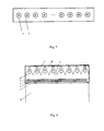
- Fig. 7 is a schematic view of the disposition of the standard light source in the device for detecting a transmittivity spectrum of the light guiding plate of embodiment of the invention.
- Fig. 8 is a partial top view of the device for detecting a transmittivity spectrum of the light guiding plate according to the embodiment of the invention, with the mixing cavity unit shown in a cross section.
- 1 standard light source
- 2 lamp reflection cover
- 3 mixing cavity unit
- 4 light filter
- 5 light homogenizer
- 6 adjustable light-leaking slit
- 7 light-passing slit
- 8 base
- 9 spacer
- 10 reflecting sheet
- 11 light guiding plate to be detected
- 12 detecting lens
- 13 mirror
- 14 incident surface
- 15 exiting surface
- 16 lamp reflection case.
- a backlight in a liquid crystal display usually uses a cold cathode fluorescent lamp or a white light LED (light-emitting diode) as a light source.
- Fig. 2 and Fig. 3 show the spectrums of a cold cathode fluorescent lamp and a white light LED, respectively. It can be seen from the figures that the spectrums of the two light sources are both discontinuous. If these two light sources are used to carry out detection, then a relatively big error would occur at a wavelength with a relatively small intensity (i.e. the regions with small vertical coordinates in Fig. 2 and Fig. 3 ).
- Fig. 4 shows a spectrum of a standard light source. It can be seen from the figure that the spectrum of the standard light source is continuous. A complete spectrum of the transmittivity of a light guiding plate at different wavelengths can be measured only when a continuous spectrum is used as a light source illuminating light guiding plate. However, since the light guiding plate usually has a small thickness of about 0.4 mm ⁇ 4 mm in a side light type backlight of a liquid crystal display, it is difficult to detect with a standard light source having a matching size.
- a mixing cavity of a particular structure is used to generate a linear light source which has uniform brightness, a continuous spectrum, and a size which is adapted to the size of the light guiding plate of the side light type backlight of the liquid crystal display, for detecting of the transmittivity spectrum of the light guiding plate, which solves the technical problem that the transmittivity spectrum of the light guiding plate can not be detected.
- Figs. 5-8 show a device for detecting a transmittivity spectrum of the light guiding plate provided according to the embodiment of the invention, the detect device comprising:
- a mixing cavity unit 3 for providing a linear light source which has uniform brightness and a continuous spectrum to a light guiding plate to be detected 11;
- a light guiding plate placing unit located at a side of the mixing cavity unit 3, on which the light guiding plate to be detected is disposed to receive light from the mixing cavity unit;
- a detecting lens 12 disposed above the light guiding plate placing unit for detecting the spectrum.
- the device for detecting a transmittivity spectrum of a light guiding plate has a simple structure, is easy to operate, and calculates the transmittivity spectrum of the light guiding plate of a side light type by measuring the incident light spectrum and the exiting light spectrum of the light guiding plate, so as to provide references for design and quality control of the backlight.
- the mixing cavity unit 3 comprises: a mixing cavity case 16, a lamp reflection cover 2 disposed in the mixing cavity case 16, and a standard light source 1 disposed in the lamp reflection cover 2.
- a light-passing slit 7 is disposed at a side of the mixing cavity case 16, through which the light of the standard light source 1 passes to form a linear light source.
- the lamp reflection cover 2 is consisted of a plurality of curved surface units, each having a vertical mid-splitting line that is a part of an ellipse and a horizontal mid-splitting line that is a part of a parabola.
- the focus of the parabola of the horizontal mid-splitting line is coincident with a first focus of the two focus of the ellipse of the vertical mid-splitting line.
- the standard light source 1 comprises a plurality of standard lamps.
- Each of the standard lamps is preferably disposed on the first focus of the ellipse of the vertical mid-splitting line of one of the curved surface units.
- the light-passing slit 7 passes through second focuses of the ellipses of the vertical mid-splitting lines of the plurality of the curved surface units of the lamp reflection cover. This enables the light from the standard light source to converge at the light-passing slit 7 again and to illuminate the incident surface of the light guiding plate to be detected effectively.
- the plurality of standard lamps may be connected in series. This may help to improve uniformity of the light.
- a light filter 4, a light homogenizer 5 and an adjustable light-leaking slit 6 may be disposed in this order between the standard light source 1 and the light-passing slit 7.
- the light filter 4 functions to filter the spectrum of the standard light source 1 to select a spectrum with particular band to detect, so as to precisely detect the transmittivity spectrum of the light guiding plate with different bands.
- the light homogenizer 5 functions to homogenize the light in the horizontal direction to make the light bar composed of the plurality of standard lamps have uniform brightness in the horizontal direction, avoiding the alternation of brightness and darkness within the light guiding plate to be detected 11, so as to enhance the precision of the detection.
- the adjustable light-leaking slit 6 functions to make the width of light from the light-passing slit 7 adjustable by replacing the light-leaking slit with another slit having a different width so as to match light guiding plates to be detected 11 with different thickness.
- the light guiding plate placing unit is constructed to enable alignment of exiting surfaces of light guiding plates having different thicknesses with the light-passing slit to ensure sufficient incident efficiency.
- the light guiding plate placing unit is composed of a base 8, spacers 9 (only one of them is shown), and a reflecting sheet 10.
- the base 8 has a structure with a certain height and a flattened surface, which has an upper surface slightly lower than the light-passing slit 7 in the mixing cavity unit 3. Disposing the spacers 9 of different heights on the base 8 enables flushing middle planes of light guiding plates with different thicknesses with a central plane of the light-passing slit 7 to achieve the best incident efficiency.
- the reflecting sheet 10 which functions the same as the reflecting sheet in the backlight of the liquid crystal display, is disposed on the spacer 9.
- the light guiding plate to be detected 11 is disposed on the reflecting sheet 10, and the exiting surface of the light guiding plate to be detected 11 faces upward and its incident surface is corresponding to the light-passing slit 7 of the mixing cavity 3.
- the spacer 9 may not be disposed between the base 8 and the reflecting sheet 10 as required.
- the detecting lens 12 is located right above the light guiding plate to be detected 11, and preferably can move horizontally between a position right above a center of the light guiding plate to be detected 11 and a position right above the incident surface of the light guiding plate to be detected 11.
- the device for detecting a transmittivity spectrum of a light guiding plate provided by the invention has a simple structure, is easy to operate, and uses a standard illuminant as the light source, which is adjusted by the reflecting sheet and the light-passing slit to be the linear light source so as to enter a light guiding plate of the side light type, and in the device, the transmittivity spectrum of the side light type light guiding plate is calculated based on the measurements of the incident light spectrum and the exiting light spectrum of light guiding plate, so as to provide references for design and quality control of backlights.
- a method for detecting a transmittivity spectrum of the light guiding plate uses the detect device described above.
- the method comprising:
- the transmittivity spectrum of the light guiding plate the exiting light spectrum/the incident light spectrum.
- the method for detecting a transmittivity spectrum of the light guiding plate provided by the invention is easy to operate, uses a standard illuminant as the light source, in which the light source is adjusted by the reflecting sheet and the light-passing slit to be a linear light source so as to enter a light guiding plate of the side light type, and the transmittivity spectrum of the light guiding plate of the side light type is calculated based on the measurements of the incident light spectrum and the exiting light spectrum of the light guiding plate, so as to provide references for design and quality control of backlights.
- measuring the exiting light spectrum of the light guiding plate may comprises selecting spacers, and disposing a light guiding plate to be detected 11, the spacers 9 and a reflecting sheet 10 on a base 8 in this order to make the incident surface of the light guiding plate to be detected 11 correspond to the light-passing slit 7 in the mixing cavity.
- Measuring the exiting light spectrum of the light guiding plate may also comprises adjusting a width of an adjustable light-leaking slit 6 according to the thickness of the light guiding plate to be detected to make the width of the light-leaking slit smaller than the thickness of the light guiding plate.
- measuring the exiting light spectrum of the light guiding plate is performed when the detecting lens is located right above the center of the light guiding plate to be detected.
- measuring the incident light spectrum of the light guiding plate may comprise:
- the exiting light spectrum detect After the exiting light spectrum detect is finished, keeping the state of the mixing cavity unit unchanged and removing the spacers, the reflecting sheet and the light guiding plate to be detected; mounting a 45°-angled mirror; and moving the detecting lens to image by aligning the light-leaking slit reflected from within the mirror, and reading the incident light spectrum.
- the detecting lens Since the light from the light-leaking slit is in horizontal direction whereas the detecting lens is in vertical direction, the detecting lens can not directly receive the light from the light-leaking slit. Therefore, it is required to mount a 45°-angled mirror to reflect the light into the lens. During detect, all need is to align the detecting lens to the image in the mirror to perform the detection.
- the method for detecting a transmittivity spectrum of a light guiding plate provided according to embodiments of the present invention is easy to operate, and uses a standard illuminant as the light source, in which the light source is adjusted by the reflecting sheet and the light-passing slit to be a linear light source so as to enter the side light type light guiding plate, and the transmittivity spectrum of the light guiding plate of the side light type is calculated based on measurements of the incident light spectrum and the exiting light spectrum of light guiding plate, so as to provide references for the design and quality control of the backlight.
- a standard illuminant as the light source, in which the light source is adjusted by the reflecting sheet and the light-passing slit to be a linear light source so as to enter the side light type light guiding plate, and the transmittivity spectrum of the light guiding plate of the side light type is calculated based on measurements of the incident light spectrum and the exiting light spectrum of light guiding plate, so as to provide references for the design and quality control of the backlight.
Applications Claiming Priority (1)
| Application Number | Priority Date | Filing Date | Title |
|---|---|---|---|
| CN201210293346.6A CN102829959B (zh) | 2012-08-16 | 2012-08-16 | 一种导光板透过率光谱的测试装置及方法 |
Publications (2)
| Publication Number | Publication Date |
|---|---|
| EP2698625A1 true EP2698625A1 (de) | 2014-02-19 |
| EP2698625B1 EP2698625B1 (de) | 2016-09-14 |
Family
ID=47333173
Family Applications (1)
| Application Number | Title | Priority Date | Filing Date |
|---|---|---|---|
| EP13175741.1A Not-in-force EP2698625B1 (de) | 2012-08-16 | 2013-07-09 | Vorrichtung und Verfahren zur Bestimmung der spektralen Durchlässigkeit einer Lichtleiterplatte |
Country Status (5)
| Country | Link |
|---|---|
| US (1) | US9442068B2 (de) |
| EP (1) | EP2698625B1 (de) |
| JP (1) | JP6319969B2 (de) |
| KR (1) | KR20140023214A (de) |
| CN (1) | CN102829959B (de) |
Families Citing this family (8)
| Publication number | Priority date | Publication date | Assignee | Title |
|---|---|---|---|---|
| CN104075878A (zh) * | 2013-03-29 | 2014-10-01 | 深圳市海洋王照明工程有限公司 | 一种导光板的均匀度测试方法 |
| CN104111238A (zh) * | 2013-04-16 | 2014-10-22 | 烁光特晶科技有限公司 | 一种光学材料透过率的测试系统及测试方法 |
| CN103792002B (zh) * | 2014-01-28 | 2016-01-20 | 北京京东方显示技术有限公司 | 一种入光效率测量装置及入光效率测量方法 |
| CN104180901A (zh) * | 2014-08-15 | 2014-12-03 | 中国科学院上海技术物理研究所 | 超窄带滤光片的透射率光谱测量装置及方法 |
| KR102231107B1 (ko) * | 2018-10-31 | 2021-03-23 | 주식회사 엘지화학 | 회절 도광판 품질 평가 시스템 및 평가 방법 |
| CN109115730A (zh) * | 2018-11-02 | 2019-01-01 | 天津津航技术物理研究所 | 基于可调谐激光的光谱透过率测试系统及方法 |
| CN110332889A (zh) * | 2019-07-19 | 2019-10-15 | 上海磊跃自动化设备有限公司 | 一种测量细小薄带凹节的测量装置 |
| CN110646974A (zh) * | 2019-08-31 | 2020-01-03 | 深圳市纳泽光电有限公司 | 一种背光模组 |
Citations (6)
| Publication number | Priority date | Publication date | Assignee | Title |
|---|---|---|---|---|
| JPH06294749A (ja) * | 1993-04-09 | 1994-10-21 | Nippon Electric Glass Co Ltd | 板ガラスの欠点検査方法 |
| WO1994027137A2 (en) * | 1993-05-18 | 1994-11-24 | University Of Utah Research Foundation | Apparatus and methods for multianalyte homogeneous fluoroimmunoassays |
| JPH10274593A (ja) * | 1997-03-31 | 1998-10-13 | Komatsu Ltd | 液晶パネルの光透過率測定装置 |
| KR20070056453A (ko) * | 2005-11-29 | 2007-06-04 | 삼성전자주식회사 | 액정패널의 투과율 측정장치 |
| US20070171661A1 (en) * | 2005-12-16 | 2007-07-26 | Jean-Louis Desvaud | Striplight and system with high-power light-emitting diodes for an automatic fault detection system |
| WO2009118952A1 (ja) * | 2008-03-27 | 2009-10-01 | 日本電気硝子株式会社 | ガラス基板検査装置およびガラス基板検査方法 |
Family Cites Families (21)
| Publication number | Priority date | Publication date | Assignee | Title |
|---|---|---|---|---|
| US3947131A (en) * | 1974-11-04 | 1976-03-30 | Gerhard Karl | Windshield soil detector |
| JPH01189549A (ja) * | 1988-01-26 | 1989-07-28 | Asahi Glass Co Ltd | 硝子欠点検出装置 |
| JP2517368B2 (ja) | 1988-09-27 | 1996-07-24 | 株式会社小糸製作所 | 自動車用前照灯及び自動車用前照灯装置 |
| JPH04208834A (ja) * | 1990-12-04 | 1992-07-30 | Ezel Inc | 液晶パネルの検査方法 |
| US5764209A (en) * | 1992-03-16 | 1998-06-09 | Photon Dynamics, Inc. | Flat panel display inspection system |
| US6323894B1 (en) * | 1993-03-12 | 2001-11-27 | Telebuyer, Llc | Commercial product routing system with video vending capability |
| US20040135273A1 (en) * | 1995-06-27 | 2004-07-15 | Parker Jeffery R. | Methods of making a pattern of optical element shapes on a roll for use in making optical elements on or in substrates |
| JPH11337496A (ja) * | 1998-03-24 | 1999-12-10 | Ngk Insulators Ltd | 透明体の欠陥検出方法及び透明体の製造方法 |
| US6606116B1 (en) * | 2000-03-30 | 2003-08-12 | Ncr Corporation | Methods and apparatus for assessing quality of information displays |
| JP2002005815A (ja) * | 2000-06-22 | 2002-01-09 | Sumitomo Chem Co Ltd | バックライト用部材の耐久性試験方法 |
| JP2002257678A (ja) * | 2001-02-06 | 2002-09-11 | Internatl Business Mach Corp <Ibm> | 表示パネルの検査装置および検査方法 |
| US6775000B2 (en) * | 2001-12-19 | 2004-08-10 | Novalux, Inc. | Method and apparatus for wafer-level testing of semiconductor laser |
| TWI243258B (en) | 2002-11-29 | 2005-11-11 | Hon Hai Prec Ind Co Ltd | Measurement apparatus of light guide plate |
| JP2005049291A (ja) | 2003-07-31 | 2005-02-24 | Nippon Sheet Glass Co Ltd | 透明板状体の集光作用を有する微小欠点を検出する装置および方法 |
| CN101025515A (zh) * | 2006-02-23 | 2007-08-29 | 中华映管股份有限公司 | 用于液晶显示器的侧光式背光模块 |
| JP2007265882A (ja) * | 2006-03-29 | 2007-10-11 | Nec Lcd Technologies Ltd | バックライトユニット及び液晶表示装置 |
| WO2008052526A1 (de) * | 2006-10-30 | 2008-05-08 | Von Ardenne Anlagentechnik Gmbh | Lichtsender, lichtempfänger und messeinrichtung zur messung optischer eigenschaften transparenter substrate |
| JP2012007993A (ja) | 2010-06-24 | 2012-01-12 | Asahi Glass Co Ltd | 板状透明体の欠陥検査装置及びその方法 |
| CN102337099B (zh) | 2010-07-28 | 2013-06-19 | 烟台德邦科技有限公司 | 单组分可光热双重固化的胶粘剂及其制备方法 |
| US8646960B2 (en) | 2010-08-03 | 2014-02-11 | 3M Innovative Properties Company | Scanning backlight with slatless light guide |
| CN102628579B (zh) * | 2012-02-28 | 2016-05-25 | 京东方科技集团股份有限公司 | 导光板、背光模组及显示装置 |
-
2012
- 2012-08-16 CN CN201210293346.6A patent/CN102829959B/zh not_active Expired - Fee Related
-
2013
- 2013-07-09 EP EP13175741.1A patent/EP2698625B1/de not_active Not-in-force
- 2013-07-29 US US13/953,007 patent/US9442068B2/en active Active
- 2013-08-01 KR KR20130091548A patent/KR20140023214A/ko not_active Application Discontinuation
- 2013-08-16 JP JP2013169067A patent/JP6319969B2/ja not_active Expired - Fee Related
Patent Citations (6)
| Publication number | Priority date | Publication date | Assignee | Title |
|---|---|---|---|---|
| JPH06294749A (ja) * | 1993-04-09 | 1994-10-21 | Nippon Electric Glass Co Ltd | 板ガラスの欠点検査方法 |
| WO1994027137A2 (en) * | 1993-05-18 | 1994-11-24 | University Of Utah Research Foundation | Apparatus and methods for multianalyte homogeneous fluoroimmunoassays |
| JPH10274593A (ja) * | 1997-03-31 | 1998-10-13 | Komatsu Ltd | 液晶パネルの光透過率測定装置 |
| KR20070056453A (ko) * | 2005-11-29 | 2007-06-04 | 삼성전자주식회사 | 액정패널의 투과율 측정장치 |
| US20070171661A1 (en) * | 2005-12-16 | 2007-07-26 | Jean-Louis Desvaud | Striplight and system with high-power light-emitting diodes for an automatic fault detection system |
| WO2009118952A1 (ja) * | 2008-03-27 | 2009-10-01 | 日本電気硝子株式会社 | ガラス基板検査装置およびガラス基板検査方法 |
Also Published As
| Publication number | Publication date |
|---|---|
| KR20140023214A (ko) | 2014-02-26 |
| JP6319969B2 (ja) | 2018-05-09 |
| US20140049778A1 (en) | 2014-02-20 |
| CN102829959B (zh) | 2014-12-17 |
| JP2014038101A (ja) | 2014-02-27 |
| CN102829959A (zh) | 2012-12-19 |
| US9442068B2 (en) | 2016-09-13 |
| EP2698625B1 (de) | 2016-09-14 |
Similar Documents
| Publication | Publication Date | Title |
|---|---|---|
| US9442068B2 (en) | Device and a method for detecting a transmittivity spectrum of a light guiding plate | |
| US9291766B2 (en) | Color deviation balance thin film, side-type backlight module and liquid crystal display device | |
| US9740033B2 (en) | Test apparatus of a direct-light-type backlight module | |
| CN102879949B (zh) | 液晶显示模组 | |
| US10914982B2 (en) | Backlight module and display device | |
| KR101418641B1 (ko) | 휘도 증가를 위한 엘이디 광원을 갖는 실내외 액정표시장치 | |
| KR20190113018A (ko) | 레인보우 무라 측정장치 | |
| US20120287626A1 (en) | Led illumination structure without light guide plate | |
| CN105137526A (zh) | 一种背光模组、背光模组的制造工艺及显示装置 | |
| US20140177273A1 (en) | Backlight module using laser emitters as light source | |
| CN202266945U (zh) | 侧光式背光模组 | |
| US9405149B2 (en) | Direct backlight module | |
| US8908123B2 (en) | Direct-light type backlight module and liquid crystal display | |
| US20160274386A1 (en) | Detecting device for light-emitting property of light source | |
| CN102691922B (zh) | 提升背光模组中央点亮度的灯条制作方法 | |
| EP3144581B1 (de) | Rückbeleuchtungsmodul und anzeigevorrichtung | |
| US20170146728A1 (en) | Backlight module and display device | |
| US20160209571A1 (en) | Backlight module and display device | |
| JP2004253308A (ja) | 面状光源及びそれを用いた液晶表示装置 | |
| US20090096955A1 (en) | Liquid Crystal Display Appliance and Lighting System | |
| CN102767740A (zh) | 一种侧边式激光背光模组及其显示器 | |
| KR101075272B1 (ko) | 백라이트유닛 | |
| US20170082793A1 (en) | Backlight module, display module and electronic device | |
| CN214225642U (zh) | 一种蓝、白光组合背光源 | |
| US9400348B2 (en) | Display backlight unit having reflecting structure for reducing hotspots |
Legal Events
| Date | Code | Title | Description |
|---|---|---|---|
| AK | Designated contracting states |
Kind code of ref document: A1 Designated state(s): AL AT BE BG CH CY CZ DE DK EE ES FI FR GB GR HR HU IE IS IT LI LT LU LV MC MK MT NL NO PL PT RO RS SE SI SK SM TR |
|
| AX | Request for extension of the european patent |
Extension state: BA ME |
|
| PUAI | Public reference made under article 153(3) epc to a published international application that has entered the european phase |
Free format text: ORIGINAL CODE: 0009012 |
|
| 17P | Request for examination filed |
Effective date: 20140819 |
|
| RBV | Designated contracting states (corrected) |
Designated state(s): AL AT BE BG CH CY CZ DE DK EE ES FI FR GB GR HR HU IE IS IT LI LT LU LV MC MK MT NL NO PL PT RO RS SE SI SK SM TR |
|
| GRAP | Despatch of communication of intention to grant a patent |
Free format text: ORIGINAL CODE: EPIDOSNIGR1 |
|
| INTG | Intention to grant announced |
Effective date: 20160503 |
|
| GRAS | Grant fee paid |
Free format text: ORIGINAL CODE: EPIDOSNIGR3 |
|
| GRAA | (expected) grant |
Free format text: ORIGINAL CODE: 0009210 |
|
| AK | Designated contracting states |
Kind code of ref document: B1 Designated state(s): AL AT BE BG CH CY CZ DE DK EE ES FI FR GB GR HR HU IE IS IT LI LT LU LV MC MK MT NL NO PL PT RO RS SE SI SK SM TR |
|
| REG | Reference to a national code |
Ref country code: GB Ref legal event code: FG4D |
|
| REG | Reference to a national code |
Ref country code: CH Ref legal event code: EP |
|
| REG | Reference to a national code |
Ref country code: IE Ref legal event code: FG4D |
|
| REG | Reference to a national code |
Ref country code: AT Ref legal event code: REF Ref document number: 829524 Country of ref document: AT Kind code of ref document: T Effective date: 20161015 |
|
| REG | Reference to a national code |
Ref country code: DE Ref legal event code: R096 Ref document number: 602013011372 Country of ref document: DE |
|
| REG | Reference to a national code |
Ref country code: NL Ref legal event code: FP |
|
| REG | Reference to a national code |
Ref country code: LT Ref legal event code: MG4D |
|
| PG25 | Lapsed in a contracting state [announced via postgrant information from national office to epo] |
Ref country code: RS Free format text: LAPSE BECAUSE OF FAILURE TO SUBMIT A TRANSLATION OF THE DESCRIPTION OR TO PAY THE FEE WITHIN THE PRESCRIBED TIME-LIMIT Effective date: 20160914 Ref country code: FI Free format text: LAPSE BECAUSE OF FAILURE TO SUBMIT A TRANSLATION OF THE DESCRIPTION OR TO PAY THE FEE WITHIN THE PRESCRIBED TIME-LIMIT Effective date: 20160914 Ref country code: LT Free format text: LAPSE BECAUSE OF FAILURE TO SUBMIT A TRANSLATION OF THE DESCRIPTION OR TO PAY THE FEE WITHIN THE PRESCRIBED TIME-LIMIT Effective date: 20160914 Ref country code: NO Free format text: LAPSE BECAUSE OF FAILURE TO SUBMIT A TRANSLATION OF THE DESCRIPTION OR TO PAY THE FEE WITHIN THE PRESCRIBED TIME-LIMIT Effective date: 20161214 Ref country code: HR Free format text: LAPSE BECAUSE OF FAILURE TO SUBMIT A TRANSLATION OF THE DESCRIPTION OR TO PAY THE FEE WITHIN THE PRESCRIBED TIME-LIMIT Effective date: 20160914 |
|
| REG | Reference to a national code |
Ref country code: AT Ref legal event code: MK05 Ref document number: 829524 Country of ref document: AT Kind code of ref document: T Effective date: 20160914 |
|
| PG25 | Lapsed in a contracting state [announced via postgrant information from national office to epo] |
Ref country code: GR Free format text: LAPSE BECAUSE OF FAILURE TO SUBMIT A TRANSLATION OF THE DESCRIPTION OR TO PAY THE FEE WITHIN THE PRESCRIBED TIME-LIMIT Effective date: 20161215 Ref country code: LV Free format text: LAPSE BECAUSE OF FAILURE TO SUBMIT A TRANSLATION OF THE DESCRIPTION OR TO PAY THE FEE WITHIN THE PRESCRIBED TIME-LIMIT Effective date: 20160914 Ref country code: SE Free format text: LAPSE BECAUSE OF FAILURE TO SUBMIT A TRANSLATION OF THE DESCRIPTION OR TO PAY THE FEE WITHIN THE PRESCRIBED TIME-LIMIT Effective date: 20160914 |
|
| PG25 | Lapsed in a contracting state [announced via postgrant information from national office to epo] |
Ref country code: EE Free format text: LAPSE BECAUSE OF FAILURE TO SUBMIT A TRANSLATION OF THE DESCRIPTION OR TO PAY THE FEE WITHIN THE PRESCRIBED TIME-LIMIT Effective date: 20160914 Ref country code: RO Free format text: LAPSE BECAUSE OF FAILURE TO SUBMIT A TRANSLATION OF THE DESCRIPTION OR TO PAY THE FEE WITHIN THE PRESCRIBED TIME-LIMIT Effective date: 20160914 |
|
| PG25 | Lapsed in a contracting state [announced via postgrant information from national office to epo] |
Ref country code: CZ Free format text: LAPSE BECAUSE OF FAILURE TO SUBMIT A TRANSLATION OF THE DESCRIPTION OR TO PAY THE FEE WITHIN THE PRESCRIBED TIME-LIMIT Effective date: 20160914 Ref country code: SK Free format text: LAPSE BECAUSE OF FAILURE TO SUBMIT A TRANSLATION OF THE DESCRIPTION OR TO PAY THE FEE WITHIN THE PRESCRIBED TIME-LIMIT Effective date: 20160914 Ref country code: IS Free format text: LAPSE BECAUSE OF FAILURE TO SUBMIT A TRANSLATION OF THE DESCRIPTION OR TO PAY THE FEE WITHIN THE PRESCRIBED TIME-LIMIT Effective date: 20170114 Ref country code: PT Free format text: LAPSE BECAUSE OF FAILURE TO SUBMIT A TRANSLATION OF THE DESCRIPTION OR TO PAY THE FEE WITHIN THE PRESCRIBED TIME-LIMIT Effective date: 20170116 Ref country code: ES Free format text: LAPSE BECAUSE OF FAILURE TO SUBMIT A TRANSLATION OF THE DESCRIPTION OR TO PAY THE FEE WITHIN THE PRESCRIBED TIME-LIMIT Effective date: 20160914 Ref country code: BG Free format text: LAPSE BECAUSE OF FAILURE TO SUBMIT A TRANSLATION OF THE DESCRIPTION OR TO PAY THE FEE WITHIN THE PRESCRIBED TIME-LIMIT Effective date: 20161214 Ref country code: BE Free format text: LAPSE BECAUSE OF FAILURE TO SUBMIT A TRANSLATION OF THE DESCRIPTION OR TO PAY THE FEE WITHIN THE PRESCRIBED TIME-LIMIT Effective date: 20160914 Ref country code: SM Free format text: LAPSE BECAUSE OF FAILURE TO SUBMIT A TRANSLATION OF THE DESCRIPTION OR TO PAY THE FEE WITHIN THE PRESCRIBED TIME-LIMIT Effective date: 20160914 Ref country code: PL Free format text: LAPSE BECAUSE OF FAILURE TO SUBMIT A TRANSLATION OF THE DESCRIPTION OR TO PAY THE FEE WITHIN THE PRESCRIBED TIME-LIMIT Effective date: 20160914 Ref country code: AT Free format text: LAPSE BECAUSE OF FAILURE TO SUBMIT A TRANSLATION OF THE DESCRIPTION OR TO PAY THE FEE WITHIN THE PRESCRIBED TIME-LIMIT Effective date: 20160914 |
|
| REG | Reference to a national code |
Ref country code: FR Ref legal event code: PLFP Year of fee payment: 5 |
|
| REG | Reference to a national code |
Ref country code: DE Ref legal event code: R097 Ref document number: 602013011372 Country of ref document: DE |
|
| PG25 | Lapsed in a contracting state [announced via postgrant information from national office to epo] |
Ref country code: IT Free format text: LAPSE BECAUSE OF FAILURE TO SUBMIT A TRANSLATION OF THE DESCRIPTION OR TO PAY THE FEE WITHIN THE PRESCRIBED TIME-LIMIT Effective date: 20160914 |
|
| PLBE | No opposition filed within time limit |
Free format text: ORIGINAL CODE: 0009261 |
|
| STAA | Information on the status of an ep patent application or granted ep patent |
Free format text: STATUS: NO OPPOSITION FILED WITHIN TIME LIMIT |
|
| PG25 | Lapsed in a contracting state [announced via postgrant information from national office to epo] |
Ref country code: DK Free format text: LAPSE BECAUSE OF FAILURE TO SUBMIT A TRANSLATION OF THE DESCRIPTION OR TO PAY THE FEE WITHIN THE PRESCRIBED TIME-LIMIT Effective date: 20160914 |
|
| REG | Reference to a national code |
Ref country code: DE Ref legal event code: R082 Ref document number: 602013011372 Country of ref document: DE Representative=s name: KLUNKER IP PATENTANWAELTE PARTG MBB, DE |
|
| 26N | No opposition filed |
Effective date: 20170615 |
|
| PG25 | Lapsed in a contracting state [announced via postgrant information from national office to epo] |
Ref country code: SI Free format text: LAPSE BECAUSE OF FAILURE TO SUBMIT A TRANSLATION OF THE DESCRIPTION OR TO PAY THE FEE WITHIN THE PRESCRIBED TIME-LIMIT Effective date: 20160914 |
|
| REG | Reference to a national code |
Ref country code: CH Ref legal event code: PL |
|
| REG | Reference to a national code |
Ref country code: IE Ref legal event code: MM4A |
|
| PG25 | Lapsed in a contracting state [announced via postgrant information from national office to epo] |
Ref country code: LI Free format text: LAPSE BECAUSE OF NON-PAYMENT OF DUE FEES Effective date: 20170731 Ref country code: IE Free format text: LAPSE BECAUSE OF NON-PAYMENT OF DUE FEES Effective date: 20170709 Ref country code: CH Free format text: LAPSE BECAUSE OF NON-PAYMENT OF DUE FEES Effective date: 20170731 |
|
| REG | Reference to a national code |
Ref country code: FR Ref legal event code: PLFP Year of fee payment: 6 |
|
| PG25 | Lapsed in a contracting state [announced via postgrant information from national office to epo] |
Ref country code: LU Free format text: LAPSE BECAUSE OF NON-PAYMENT OF DUE FEES Effective date: 20170709 |
|
| PG25 | Lapsed in a contracting state [announced via postgrant information from national office to epo] |
Ref country code: MT Free format text: LAPSE BECAUSE OF NON-PAYMENT OF DUE FEES Effective date: 20170709 |
|
| PG25 | Lapsed in a contracting state [announced via postgrant information from national office to epo] |
Ref country code: AL Free format text: LAPSE BECAUSE OF FAILURE TO SUBMIT A TRANSLATION OF THE DESCRIPTION OR TO PAY THE FEE WITHIN THE PRESCRIBED TIME-LIMIT Effective date: 20160914 |
|
| PG25 | Lapsed in a contracting state [announced via postgrant information from national office to epo] |
Ref country code: HU Free format text: LAPSE BECAUSE OF FAILURE TO SUBMIT A TRANSLATION OF THE DESCRIPTION OR TO PAY THE FEE WITHIN THE PRESCRIBED TIME-LIMIT; INVALID AB INITIO Effective date: 20130709 Ref country code: MC Free format text: LAPSE BECAUSE OF FAILURE TO SUBMIT A TRANSLATION OF THE DESCRIPTION OR TO PAY THE FEE WITHIN THE PRESCRIBED TIME-LIMIT Effective date: 20160914 |
|
| PG25 | Lapsed in a contracting state [announced via postgrant information from national office to epo] |
Ref country code: CY Free format text: LAPSE BECAUSE OF NON-PAYMENT OF DUE FEES Effective date: 20160914 |
|
| PG25 | Lapsed in a contracting state [announced via postgrant information from national office to epo] |
Ref country code: MK Free format text: LAPSE BECAUSE OF FAILURE TO SUBMIT A TRANSLATION OF THE DESCRIPTION OR TO PAY THE FEE WITHIN THE PRESCRIBED TIME-LIMIT Effective date: 20160914 |
|
| PG25 | Lapsed in a contracting state [announced via postgrant information from national office to epo] |
Ref country code: TR Free format text: LAPSE BECAUSE OF FAILURE TO SUBMIT A TRANSLATION OF THE DESCRIPTION OR TO PAY THE FEE WITHIN THE PRESCRIBED TIME-LIMIT Effective date: 20160914 |
|
| PGFP | Annual fee paid to national office [announced via postgrant information from national office to epo] |
Ref country code: FR Payment date: 20210611 Year of fee payment: 9 |
|
| PGFP | Annual fee paid to national office [announced via postgrant information from national office to epo] |
Ref country code: NL Payment date: 20210716 Year of fee payment: 9 Ref country code: GB Payment date: 20210616 Year of fee payment: 9 |
|
| PGFP | Annual fee paid to national office [announced via postgrant information from national office to epo] |
Ref country code: DE Payment date: 20210616 Year of fee payment: 9 |
|
| REG | Reference to a national code |
Ref country code: DE Ref legal event code: R119 Ref document number: 602013011372 Country of ref document: DE |
|
| REG | Reference to a national code |
Ref country code: NL Ref legal event code: MM Effective date: 20220801 |
|
| GBPC | Gb: european patent ceased through non-payment of renewal fee |
Effective date: 20220709 |
|
| PG25 | Lapsed in a contracting state [announced via postgrant information from national office to epo] |
Ref country code: FR Free format text: LAPSE BECAUSE OF NON-PAYMENT OF DUE FEES Effective date: 20220731 |
|
| PG25 | Lapsed in a contracting state [announced via postgrant information from national office to epo] |
Ref country code: GB Free format text: LAPSE BECAUSE OF NON-PAYMENT OF DUE FEES Effective date: 20220709 Ref country code: DE Free format text: LAPSE BECAUSE OF NON-PAYMENT OF DUE FEES Effective date: 20230201 |
|
| PG25 | Lapsed in a contracting state [announced via postgrant information from national office to epo] |
Ref country code: NL Free format text: LAPSE BECAUSE OF NON-PAYMENT OF DUE FEES Effective date: 20220801 |