EP2696018A2 - Pivotable guiding scissors, bearing device and guidance system for parallel vent window - Google Patents
Pivotable guiding scissors, bearing device and guidance system for parallel vent window Download PDFInfo
- Publication number
- EP2696018A2 EP2696018A2 EP13003991.0A EP13003991A EP2696018A2 EP 2696018 A2 EP2696018 A2 EP 2696018A2 EP 13003991 A EP13003991 A EP 13003991A EP 2696018 A2 EP2696018 A2 EP 2696018A2
- Authority
- EP
- European Patent Office
- Prior art keywords
- bearing
- frame
- wing
- pivot
- pivot bearings
- Prior art date
- Legal status (The legal status is an assumption and is not a legal conclusion. Google has not performed a legal analysis and makes no representation as to the accuracy of the status listed.)
- Granted
Links
- 238000006073 displacement reaction Methods 0.000 claims abstract description 6
- 238000010276 construction Methods 0.000 abstract description 5
- 230000008901 benefit Effects 0.000 description 3
- 230000008878 coupling Effects 0.000 description 3
- 238000010168 coupling process Methods 0.000 description 3
- 238000005859 coupling reaction Methods 0.000 description 3
- 239000000463 material Substances 0.000 description 2
- 230000007246 mechanism Effects 0.000 description 2
- 230000008859 change Effects 0.000 description 1
- 230000003750 conditioning effect Effects 0.000 description 1
- 238000013016 damping Methods 0.000 description 1
- 238000011161 development Methods 0.000 description 1
- 230000018109 developmental process Effects 0.000 description 1
- 238000004519 manufacturing process Methods 0.000 description 1
- 230000004048 modification Effects 0.000 description 1
- 238000012986 modification Methods 0.000 description 1
- 239000007779 soft material Substances 0.000 description 1
- 239000011122 softwood Substances 0.000 description 1
- 239000007787 solid Substances 0.000 description 1
- 239000011343 solid material Substances 0.000 description 1
Images

Classifications
-
- E—FIXED CONSTRUCTIONS
- E05—LOCKS; KEYS; WINDOW OR DOOR FITTINGS; SAFES
- E05D—HINGES OR SUSPENSION DEVICES FOR DOORS, WINDOWS OR WINGS
- E05D15/00—Suspension arrangements for wings
- E05D15/28—Suspension arrangements for wings supported on arms movable in horizontal plane
- E05D15/32—Suspension arrangements for wings supported on arms movable in horizontal plane with two pairs of pivoted arms
- E05D15/34—Suspension arrangements for wings supported on arms movable in horizontal plane with two pairs of pivoted arms with wings opening parallel to themselves
-
- E—FIXED CONSTRUCTIONS
- E05—LOCKS; KEYS; WINDOW OR DOOR FITTINGS; SAFES
- E05D—HINGES OR SUSPENSION DEVICES FOR DOORS, WINDOWS OR WINGS
- E05D15/00—Suspension arrangements for wings
- E05D15/28—Suspension arrangements for wings supported on arms movable in horizontal plane
- E05D15/30—Suspension arrangements for wings supported on arms movable in horizontal plane with pivoted arms and sliding guides
-
- E—FIXED CONSTRUCTIONS
- E05—LOCKS; KEYS; WINDOW OR DOOR FITTINGS; SAFES
- E05Y—INDEXING SCHEME RELATING TO HINGES OR OTHER SUSPENSION DEVICES FOR DOORS, WINDOWS OR WINGS AND DEVICES FOR MOVING WINGS INTO OPEN OR CLOSED POSITION, CHECKS FOR WINGS AND WING FITTINGS NOT OTHERWISE PROVIDED FOR, CONCERNED WITH THE FUNCTIONING OF THE WING
- E05Y2600/00—Mounting or coupling arrangements for elements provided for in this subclass
- E05Y2600/10—Adjustable or movable
- E05Y2600/30—Adjustable or movable characterised by the type of motion
- E05Y2600/32—Rotary motion
- E05Y2600/322—Rotary motion around a horizontal axis
Landscapes
- Engineering & Computer Science (AREA)
- Mechanical Engineering (AREA)
- Hinges (AREA)
- Wing Frames And Configurations (AREA)
- Specific Sealing Or Ventilating Devices For Doors And Windows (AREA)
Abstract
Description
Die Erfindung betrifft Beschläge und Lagerungen für Fenster oder Türen, insbesondere Führungs-/Ausstellscheren zum parallelen Ausstellen von Fenster- oder Türflügeln gegenüber einem Rahmen.The invention relates to fittings and bearings for windows or doors, in particular guide / Ausstellscheren for parallel issuing window or door wings against a frame.
Auf dem Gebiet von aus einem Rahmen und einem Flügel bestehenden Fenstern und Türen, insbesondere Parallel-Ausstellfenstern, werden Beschläge verwendet, um den Flügel gegenüber dem Rahmen in einem definierten Abstand und/oder Winkel lagern zu können. Bei Parallel-Ausstellfenstern kann ein in einem Fensterrahmen angeordneter Flügel beim Öffnen in vielen Fällen nur seitlich parallel versetzt zu dem Rahmen angeordnet werden, so dass der Flügel nur noch über Beschläge mit dem Rahmen verbunden ist und nicht mehr an einer der Rahmenseiten anliegt. Eine zusätzliche winkelige Anordnung kann nur dann vorgesehen sein, wenn eine Vielzahl an Beschlägen verwendet werden, nämlich mindestens vier Beschläge, und über jeden Beschlag ferner der Abstand zwischen Rahmen und Flügel frei einstellbar ist. Dann kann bei zwei der vier Beschläge ein erster Abstand und bei den anderen beiden der vier Beschläge ein zweiter Abstand eingestellt werden, und der Flügel ist winkelig gegenüber dem Rahmen angeordnet. Abgesehen von der aufwendigen Einstellung ergeben sich jedoch meist Stabilitätsprobleme.In the field of windows and doors consisting of a frame and a wing, in particular parallel-opening windows, fittings are used in order to be able to support the wing with respect to the frame at a defined distance and / or angle. In the case of parallel opening windows, a wing arranged in a window frame can in many cases only be arranged laterally offset parallel to the frame when opening, so that the wing is only connected to the frame via fittings and no longer bears against one of the frame sides. An additional angular arrangement can only be provided when a plurality of fittings are used, namely at least four fittings, and on each fitting further, the distance between the frame and wing is freely adjustable. Then, at two of the four fittings, a first distance and at the other two of the four fittings, a second distance can be adjusted, and the wing is arranged at an angle to the frame. Apart from the elaborate setting but usually arise stability problems.
Ausstelischeren bzw. Führungsscheren als eine spezielle Form von Beschlägen dienen dazu, Fenster in einer Kippstellung zu halten und in den meisten Fällen auch bei einer Bewegung von einer Schließstellung in die Kippstellung und umgekehrt zu führen. Sie haben üblicherweise beide Funktionen. Im Folgenden wird der Begriff Führungsschere verwendet, da er hervorhebt, dass auch eine Führung beim Öffnen oder Schließen der Fenster erwünscht ist. Führungsscheren können seitlich am Fensterrahmen und/oder am horizontal verlaufenden oberen Fensterrahmenteil vorgesehen sein. Es können grundsätzlich zwei Typen unterschieden werden, nämlich Dreipunkt-Führungsscheren und Vierpunkt-Führungsscheren. Beide Typen weisen jeweils zwei Scherenarme auf, die miteinander gekoppelt sind. Bei Dreipunkt-Führungsscheren sind üblicherweise zwei der drei Lagerpunkte drehbar gelagert und einer drehbar und verschiebbar. Wahlweise sind zwei Lagerpunkte drehbar und verschiebbar gelagert. Die Scherenarme sind in einem Lager aneinander gekoppelt, welches neben einer Rotation auch eine translatorische Relativbewegung zueinander zulässt, z.B. ein Langloch. Bei Vierpunkt-Führungsscheren sind üblicherweise zwei der vier Lagerpunkte drehbar gelagert und die beiden anderen drehbar und verschiebbar. Die Scherenarme sind in einem Lager aneinander gekoppelt, welches nur Rotation zueinander zulässt.Ausstelischeren or guide shears as a special form of fittings are used to keep windows in a tilted position and in most cases to move from a closed position to the tilted position and vice versa. They usually have both functions. Hereinafter The term guide shears is used, as it emphasizes that a guide when opening or closing the windows is desired. Guide shears can be provided laterally on the window frame and / or on the horizontally extending upper window frame part. Basically, two types can be distinguished, namely three-point guide shears and four-point guide shears. Both types each have two scissor arms, which are coupled together. In three-point guide shears usually two of the three bearing points are rotatably mounted and one rotatable and displaceable. Optionally, two bearing points are rotatably and slidably mounted. The scissor arms are coupled together in a bearing, which in addition to a rotation and a translational relative movement allows each other, for example, a slot. In four-point guide shears usually two of the four bearing points are rotatably mounted and the other two rotatable and displaceable. The scissor arms are coupled together in a bearing, which only allows rotation to each other.
Die Druckschrift
Die Druckschrift
Die Druckschrift
Aufgabe ist, eine einfach aufgebaute Führungsschere für ein breites Einsatzgebiet bereitzustellen.The task is to provide a simply constructed guide shears for a wide range of applications.
Diese Aufgaben werden durch eine Vierpunkt-Führungsschere gemäß Anspruch 1 und eine Lagervorrichtung gemäß Anspruch 7 sowie durch eine Führungssystem gemäß Anspruch 11 gelöst. Vorteilhafte Weiterbildungen der Erfindung werden in den Unteransprüchen erläutert.These objects are achieved by a four-point guide shears according to
Eine erfindungsgemäße Vierpunkt-Führungsschere für aus einem Rahmen und einem Flügel aufgebaute Parallel-Ausstellfenster oder -türen weist einen ersten Scherenarm und einen zweiten Scherenarm auf, welche jeweils in zwei an dem Rahmen und dem Flügel angeordneten Lagern drehbar lagerbar sind und jeweils in einem der Lager zusätzlich axial verschiebbar lagerbar sind. Erfindungsgemäß wird vorgeschlagen, an den Scherenarmen jeweils mindestens ein Schwenklager vorzusehen, über welches die Scherenarme schwenkbar lagerbar sind.A four-point guide shears according to the invention for constructed from a frame and a wing parallel-Ausstellfenster or doors has a first scissor arm and a second scissor arm, which are each rotatably storable in two arranged on the frame and the wing bearings and each in one of the camp are additionally axially displaceable storable. According to the invention, at least one pivot bearing is provided on each of the scissor arms, via which the scissor arms are pivotably mountable.
Eine Vierpunkt-Führungsschere weist somit Scherenarme mit jeweils mindestens einem Lager auf, in welchem neben einer Drehbewegung auch eine Schwenkbewegung und wahlweise auch eine translatorische Bewegung erfolgen kann. Mit anderen Worten sind die Schwenklager Lager mit drei Freiheitsgraden. Bevorzugt ist an jedem Scherenarm ein Schwenklager als radiales Gleitlager ausgebildet, welches zusätzlich eine Drehbewegung des Scherenarms gegenüber dem Schwenklager zulässt.A four-point guide shears thus has scissor arms, each with at least one bearing, in which in addition to a rotational movement, a pivoting movement and optionally also a translational movement can take place. In other words, the pivot bearings are bearings with three degrees of freedom. Preferably, a pivot bearing is designed as a radial sliding bearing on each scissor arm, which additionally allows a rotational movement of the scissor arm relative to the pivot bearing.
Bevorzugt sind an den Scherenarmen jeweils zwei Schwenklager vorgesehen, über welche die Scherenarme jeweils in beiden Lagern schwenkbar lagerbar sind, d.h. über welche beide freien Enden der Scherenarme schwenkbar lagerbar sind. Wahlweise kann es in bestimmten Fällen ausreichen, nur an zwei der vier freien Enden der Scherenarme Schwenklager vorzusehen.In each case two pivot bearings are preferably provided on the scissor arms, by means of which the scissor arms are pivotally mountable in each case in both bearings, i. over which both free ends of the scissor arms are pivotally storable. Optionally, it may be sufficient in certain cases to provide only two of the four free ends of the scissor arms pivot bearing.
Ein solcher Parallel-Ausstellmechanimus mit Vierpunkt-Führungsschere kann auch bei Klappfenstern oder -türen verwendet werden. Der Parallel-Ausstellmechanimus kann eine Vielzahl unterschiedlicher Anordnungen eines Flügels gegenüber einem Rahmen ermöglichen. Eine erfindungsgemäße Vierpunkt-Führungsschere mit Schwenklagern ist auch dazu ausgebildet, einen Flügel eines Parallel-Ausstellfensters oder einer Parallel-Ausstelltür in einem Winkel gegenüber dem Rahmen auszustellen, wobei der Flügel gegenüber dem Rahmen nach unten oder nach oben verschwenkt werden kann. Gleichzeitig kann eine gute Seitenstabilität bei einem ausgestellten Flügel sichergestellt werden, insbesondere indem die seitliche Abstützung im Wesentlichen allein durch die kreuzförmig angeordneten Scherenarme auf symmetrische Weise an Flügel und Rahmen und in verhältnismäßig weit voneinander beabstandeten Lagerpunkten erfolgt. Auch kann eine Öffnungsbegrenzung über die Führungsschere erfolgen, insbesondere indem die Schwenklager zwischen Lagerböcken angeordnet werden an welchen sie anschlagen können, wenn sie in einer Soll-Position entsprechend der gewünschten maximalen Offenstellung angeordnet sind. Sie kann auch eine Öffnungswinkelbegrenzung bereitstellen, insbesondere indem an den Schwenklagern ein Anschlag vorgesehen wird, welcher gegen einen korrespondierenden Anschlag schlägt, wenn ein Verschwenken um einen bestimmten Winkel erfolgt ist.Such a parallel Ausstellmechanimus with four-point guide scissors can also be used in folding windows or doors. The Parallel Ausstellmechanimus can allow a variety of different arrangements of a wing over a frame. An inventive Four-point guide scissors with pivot bearings is also designed to exhibit a wing of a parallel-Ausstellfensters or a parallel-issuing door at an angle relative to the frame, wherein the wing with respect to the frame can be pivoted upwards or upwards. At the same time a good lateral stability can be ensured in a flared wing, in particular by the lateral support is carried out substantially solely by the cross-shaped scissor arms in a symmetrical manner on wings and frame and in relatively widely spaced bearing points. Also, an opening limitation on the guide shears can be done, in particular by the pivot bearings are arranged between bearing blocks on which they can strike when they are arranged in a desired position corresponding to the desired maximum open position. It can also provide an opening angle limitation, in particular by providing a stop on the pivot bearings which strikes against a corresponding stop when pivoting has taken place by a certain angle.
Die Scherenarme einer erfindungsgemäßen Vierpunkt-Führungsschere sind nicht nur einseitig verschiebbar und einseitig fest am Rahmen und Flügel befestigt, sondern sind auch schwenkbar, insbesondere um eine Lagerachse, auf welcher die Scherenarme auch axial verschiebbar gelagert sind.The scissor arms of a four-point guide scissors according to the invention are not only one-sided displaceable and fixed on one side fixed to the frame and wings, but are also pivotable, in particular about a bearing axis on which the scissor arms are also mounted axially displaceable.
Als eine Schwenkbewegung ist dabei bevorzugt eine rotative Bewegung zu verstehen, welche um eine Achse erfolgt, die bei einer Anordnung der Vierpunkt-Führungsschere an einer horizontal ausgerichteten Seite eines Flügels oder Rahmens im Wesentlichen horizontal ausgerichtet ist, so dass sich die Vierpunkt-Führungsschere gegenüber dem Flügel bzw. Rahmen verschwenken kann, auch wenn der Abstand zwischen Flügel und Rahmen konstant bleibt. D.h., die Schwenklager können erfindungsgemäß eine rotative Bewegung z.B. um eine Achse ermöglichen, entlang welcher üblicherweise zwei der vier freien Enden der Vierpunkt-Führungsschere verschiebbar sind.As a pivoting movement is preferably to be understood a rotational movement, which takes place about an axis which is aligned horizontally in an arrangement of four-point guide scissors on a horizontally oriented side of a wing or frame, so that the four-point guide shear against the Wing or frame can pivot, even if the distance between the wing and frame remains constant. That is, according to the invention, the pivot bearings may be rotatable, e.g. allow about an axis along which usually two of the four free ends of the four-point guide shears are displaced.
Als eine Drehbewegung ist dabei bevorzugt eine rotative Bewegung zu verstehen, welche um eine Achse erfolgt, die bei einer Anordnung der Vierpunkt-Führungsschere an einer horizontal ausgerichteten Seite eines Flügels oder Rahmens im Wesentlichen vertikal ausgerichtet ist, so dass sich die Vierpunkt-Führungsschere gegenüber dem Flügel bzw. Rahmen verdrehen kann, um den Abstand zwischen Flügel und Rahmen zu ändern. D.h., die Drehlager ermöglichen die bei Vierpunkt-Führungsscheren per se erforderliche relative Drehung zwischen den Scherenarmen und den Lagerpunkten.As a rotational movement is to be understood preferably a rotary movement, which takes place about an axis in an arrangement of the four-point guide shears on a horizontally oriented side of a Wing or frame is oriented substantially vertically, so that the four-point guide shear can rotate relative to the wing or frame to change the distance between the wing and frame. That is, the pivot bearings allow the four-point guide shears per se required relative rotation between the scissor arms and the bearing points.
Mit anderen Worten wird erfindungsgemäß eine Vierpunkt-Führungsschere bereitgestellt, mit welcher der Flügel gegenüber dem Rahmen in einer Vielzahl unterschiedlicher Positionen angeordnet werden kann und gleichzeitig kann eine hohe Stabilität des ausgestellten Flügels und eine gute Robustheit der Lager bzw. des gesamten Ausstell-Mechanismus sichergestellt werden. Obgleich die erfindungsgemäße Führungsschere mehrere Funktionen in sich vereinen kann, ist sie einfach aufgebaut. Insbesondere kann sie symmetrisch aufgebaut sein, wobei die Symmetrieebene durch ein Scherengelenk verläuft, über welches die beiden Scherenarme aneinander gekoppelt sind.In other words, according to the present invention, there is provided a four-point guide shear, with which the wing can be arranged in a variety of different positions relative to the frame, and at the same time a high stability of the flared wing and a good ruggedness of the bearings or the whole deployment mechanism can be ensured , Although the guide shear according to the invention can combine several functions in itself, it is simple. In particular, it may be constructed symmetrically, wherein the plane of symmetry passes through a scissors joint, via which the two scissor arms are coupled together.
Eine erfindungsgemäße Führungsschere kann für Parallel-Senk-Ausstellfenster sowie für Parallel-Hebe-Ausstellfenster verwendet werden. Ferner kann sie für Senk-Klappfenster und für Hebe-Kippfenster verwendet werden. Dadurch ergibt sich ein breites Einsatzgebiet.A guide scissors according to the invention can be used for parallel-lowering opening window and for parallel lifting-Ausstellfenster. It can also be used for countersunk folding windows and lifting / tilting windows. This results in a wide field of application.
Gemäß einem Ausführungsbeispiel sind die Schwenklager dazu ausgebildet, schwenkbar um eine Lagerachse gelagert zu sein. Die Schwenklager können jeweils eine Durchführung aufweisen, welche dazu ausgebildet ist, um eine Lagerachse angeordnet und durch die Lagerachse geführt zu sein. Die Durchführung kann als zylindrische Bohrung ausgeführt sein, insbesondere als Bohrung, welche in einen massiven Teil des Schwenklagers eingebracht ist. Sie kann wahlweise auch durch ein Rohr gebildet sein, welches mit einer oder zwei Seitenplatten verbunden ist, in welchen ein Bolzen zur Kopplung des Scherenarms an das Schwenklager vorgesehen sein kann. Die Durchführung kann als leichtgängiges Gleitlager aus einem leichtlaufenden Gleitlagermaterial mit einem geringen Reibungsbeiwert ausgeführt sein.According to one embodiment, the pivot bearings are adapted to be pivotally mounted about a bearing axis. The pivot bearings may each have a passage, which is designed to be arranged around a bearing axis and guided by the bearing axis. The implementation may be designed as a cylindrical bore, in particular as a bore, which is introduced into a solid part of the pivot bearing. It can optionally also be formed by a tube which is connected to one or two side plates, in which a bolt may be provided for coupling the scissor arm to the pivot bearing. The implementation can be designed as a smooth slide bearing from a smooth running plain bearing material with a low coefficient of friction.
Die Schwenklager können wahlweise eine oder zwei Seitenplatten aufweisen, über welche sie an den jeweiligen Scherenarm gekoppelt sind. ZweiThe pivot bearings may optionally have one or two side plates, via which they are coupled to the respective scissor arm. Two
Seitenplatten haben den Vorteil einer stabileren Führung und einer besseren Lagerung eines Bolzens.Side plates have the advantage of a more stable guidance and a better bearing of a bolt.
Gemäß einem Ausführungsbeispiel, welches auf einem der zuvor beschriebenen Ausführungsbeispiele basieren kann, weisen beide Scherenarme jeweils zwei Schwenklager auf, wobei bei jedem Scherenarm das eine der Schwenklager als festes Schwenklager und das andere der Schwenklager als verschiebbares Schwenklager ausgebildet ist. Dabei können die Schwenklager auch dazu ausgebildet sein, die Scherenarme drehbar zu lagern. Auf diese Weise kann in einem Schwenklager die Lagerung um eine Drehachse, die Lagerung um eine Schwenkachse sowie die Lagerung entlang einer translatorischen Achse erfolgen.According to an embodiment, which may be based on one of the embodiments described above, both scissor arms each have two pivot bearings, wherein each scissor arm one of the pivot bearing is designed as a fixed pivot bearing and the other of the pivot bearing as a sliding pivot bearing. In this case, the pivot bearings can also be designed to rotatably support the scissor arms. In this way, in a pivot bearing, the storage about a rotational axis, the storage about a pivot axis and the storage along a translational axis take place.
Als festes Schwenklager bzw. feststehendes Schwenklager ist bevorzugt ein Schwenklager zu verstehen, welches an einer Lagerachse fixiert werden kann. Als verschiebbares Schwenklager ist bevorzugt ein Schwenklager zu verstehen, welches entlang an einer Lagerachse um welche es schwenkbar ist verschoben werden kann.As a fixed pivot bearing or fixed pivot bearing is preferably a pivot bearing to understand, which can be fixed to a bearing axis. As a sliding pivot bearing is preferably a pivot bearing to understand, which can be moved along which it is pivotable along a bearing axis.
Die festen Schwenklager können dadurch als feste Schwenklager ausgebildet sein, dass sie Feststellmittel aufweisen, über welche sie z.B. an einer Lagerachse in einer bestimmten Position feststellbar, d.h. fixierbar sind.The fixed pivot bearings may be formed as fixed pivot bearings in that they have locking means over which they are e.g. ascertainable on a bearing axis in a certain position, i. can be fixed.
Bevorzugt sind die verschiebbaren Schwenklager verschiebbar auf der Lagerachse ausgebildet, um welche sie auch schwenkbar sind. Dies kann über Schwenklager realisiert werden, welche eine Durchführung für die Lagerachse sowie eine sandwichartige Schlitzführung aufweisen, wobei die Schlitzführung dazu vorgesehen sind, die freien Enden der Scherenarme seitlich zu führen und zu stützen. Hierdurch kann ein einfacher und robuster Aufbau bereitgestellt werden. Die Durchführung kann in einer Art Hülse angeordnet sein, und an der Hülse können zwei Seitenplatten abstehen, zwischen welchen ein freies Ende eines Scherenarms geführt werden kann. Dabei kann das Schwenklager in einer Draufsicht eine rechteckförmige Grundfläche aufweisen, und in einer Seitenansicht ein U-förmige Außenkontur beschreiben, wobei die Schenkel des U den beiden Seitenplatten entsprechen und die Rundung des U der äußeren Mantelfläche der Hülse.Preferably, the displaceable pivot bearings are slidably formed on the bearing axis, by which they are also pivotable. This can be realized via pivot bearings, which have a passage for the bearing axis and a sandwich-like slot guide, wherein the slot guide are provided to guide the free ends of the scissor arms laterally and support. As a result, a simple and robust construction can be provided. The passage can be arranged in a kind of sleeve, and on the sleeve can protrude two side plates, between which a free end of a scissor arm can be performed. In this case, the pivot bearing may have a rectangular base surface in a plan view, and describe in a side view a U-shaped outer contour, wherein the legs of the U correspond to the two side plates and the rounding of the U of the outer surface of the sleeve.
Dadurch dass die Schwenklager dazu ausgebildet sind, die Scherenarme drehbar zu lagern, wird eine einfache Konstruktion bereitgestellt, bei welcher die Lagerung der Scherenarme über eine einzige Schnittstelle zu dem Rahmen bzw. Flügel erfolgen kann, nämlich eine Kupplung die mit der Lagerachse zusammenwirken kann. Die Drehbewegung kann relativ zwischen dem jeweiligen Scherenarm und den zugehörigen Schwenklagern erfolgen. Vorteilhaft bei dieser Konstruktion ist nicht nur der einfache Aufbau, sondern auch die Möglichkeit, die Scherenarme allein über die Drehlagerung von den Schwenklagern bzw. den Lagerachsen zu entkoppeln. Dies erleichtert eine Montage bzw. Demontage.Characterized in that the pivot bearings are adapted to rotatably support the scissor arms, a simple construction is provided, in which the storage of the scissor arms can take place via a single interface to the frame or wing, namely a coupling which can cooperate with the bearing axis. The rotational movement can be carried out relatively between the respective scissor arm and the associated pivot bearings. An advantage of this design is not only the simple structure, but also the ability to decouple the scissor arms alone on the pivot bearing of the pivot bearings and the bearing axes. This facilitates assembly or disassembly.
Gemäß einem Ausführungsbeispiel, welches auf einem der zuvor beschriebenen Ausführungsbeispiele basieren kann, ist mindestens eines der verschiebbaren Schwenklager einstellbar gebremst in Verschieberichtung ausgeführt ist. Die Verschieberichtung entspricht bevorzugt einer Ausrichtung einer Lagerachse, auf welcher die Schwenklager gelagert sein können. Mit anderen Worten kann ein Schwenklager, welches in Verschieberichtung gebremst oder ganz abgeblockt ist, von einem radialen Gleitlager in ein Radial-Axial-Lager (Radiaxiager) umgewandelt werden, welches auch die Drehbewegung zwischen Schwenklager und Scherenarm zulässt (Freiheitsgrad 2 anstelle 3).According to an embodiment, which may be based on one of the embodiments described above, at least one of the displaceable pivot bearing is adjustable braked in the direction of displacement is executed. The displacement direction preferably corresponds to an orientation of a bearing axis on which the pivot bearings can be mounted. In other words, a pivot bearing, which is braked in the direction of displacement or completely blocked, be converted from a radial sliding bearing in a radial-axial bearing (Radiaxiager), which also allows the rotation between the pivot bearing and scissor arm (degree of freedom 2 instead of 3).
Die verschiebbaren Schwenklager können als Bremsmittel z.B. eine Schraube mit flacher Unterseite oder einen Keil in Richtung einer Lagerachse verschiebbaren aufweisen, und das Bremsmittel kann zum einen im Hinblick auf eine bevorzugte Reibung zwischen dem Schwenklager und der Lagerachse eingestellt werden, zum anderen aber auch als Fixierung in einer bestimmten Position und damit der Festlegung eines bestimmten Abstands bzw. Winkels des Flügels gegenüber dem Rahmen dienen. Die verschiebbaren Schwenklager können auch eine zusätzliche Buchse aufweisen, welche über ein Bremsmittel an die Lagerachse gepresst werden kann.The displaceable pivot bearings may have as a braking means, for example, a screw with a flat bottom or a wedge displaceable in the direction of a bearing axis, and the braking means can be adjusted on the one hand with regard to a preferred friction between the pivot bearing and the bearing axis, on the other hand as a fixation in serve a certain position and thus the determination of a certain distance or angle of the wing relative to the frame. The displaceable pivot bearings may also have an additional bushing, which can be pressed by a braking means to the bearing axis.
Durch einstellbar gebremste Schwenklager kann ein Flügel unempfindlich gegenüber Wind gelagert werden. Ein Schlagen des Flügels im Wind kann auf einfache Weise unterbunden werden und den lokalen Wetterverhältnissen angepasst werden. Es ist z.B. möglich, den Flügel stufenlos in jeder beliebigen Position gegenüber dem Rahmen stabil zu lagern.By adjustable braked pivot bearing a wing can be stored insensitive to wind. A hitting the wing in the wind can be easily prevented and adapted to the local weather conditions. It is e.g. possible to store the wing stably in any position relative to the frame stable.
Gemäß einem Ausführungsbeispiel, welches auf einem der zuvor beschriebenen Ausführungsbeispiele basieren kann, weisen die festen Schwenklager Feststellmittel zum Fixieren der festen Schwenklager an einer Lagerachse auf.According to an embodiment, which may be based on one of the previously described embodiments, the fixed pivot bearings have locking means for fixing the fixed pivot bearings to a bearing axle.
Über die Feststellmittel können die festen Schwenklager z.B. an einer Lagerachse fixierbar sein. Die Feststellmittel können als in einem Innengewinde an dem jeweiligen festen Schwenklager geführte Feststellschrauben ausgeführt sein, welche in die Lagerachse geschraubt werden, oder sie können als mit dem jeweiligen festen Schwenklager verbundene Klemmringe ausgeführt sein.By way of the locking means, the fixed pivot bearings may be e.g. be fixable on a bearing axis. The locking means can be designed as guided in an internal thread on the respective fixed pivot bearing locking screws which are screwed into the bearing axis, or they can be designed as connected to the respective fixed pivot bearing clamping rings.
Gemäß einem Ausführungsbeispiel, welches auf einem der zuvor beschriebenen Ausführungsbeispiele basieren kann, sind die Schwenklager jeweils über einen Bolzen an die Scherenarme gekoppelt, wobei der Bolzen als Drehachse ausgebildet ist, um welche die Schwenklager drehbar lagerbar sind. Hierdurch kann eine einfache und robuste Kopplung zwischen Scherenarmen, Schwenklagern und Rahmen bzw. Flügel erfolgen.According to an embodiment, which may be based on one of the embodiments described above, the pivot bearings are each coupled via a bolt to the scissor arms, wherein the bolt is formed as a rotation axis about which the pivot bearings are rotatably storable. This allows a simple and robust coupling between scissor arms, pivot bearings and frame or wing done.
Zumindest eine der zuvor genannten Aufgaben wird wie erwähnt auch durch eine Lagervorrichtung gemäß Anspruch 7 gelöst. Die Lagervorrichtung ist für parallel-Ausstellfenster oder -türen mit einem Rahmen und einem Flügel vorgesehen dazu ausgebildet, einen ersten Scherenarm und einen zweiten Scherenarm drehbar zu lagern und einen der Scherenarme axial verschiebbar zu lagern, wobei die Lagervorrichtung eine Lagerachse aufweist, welche dazu ausgebildet ist, zwei Schwenklager schwenkbar um die Lagerachse und eines der Schwenklager axial verschiebbar an der Lagerachse zu lagern. Die Lagervorrichtung kann die Schwenklager auch selbst aufweisen bzw. bereitstellen, falls die Schwenklager nicht bereits an Scherenarmen einer Führungsschere vorgesehen sind.As mentioned, at least one of the aforementioned objects is also achieved by a bearing device according to claim 7. The bearing device is designed for parallel-opening windows or doors with a frame and a wing designed to rotatably support a first scissor arm and a second scissor arm and axially slidably support one of the scissor arms, wherein the bearing device has a bearing axis, which is formed , Two pivot bearings pivotally mounted about the bearing axis and one of the pivot bearings axially displaceable on the bearing axis. The bearing device may also provide the pivot bearings themselves, if the pivot bearings are not already provided on scissor arms of a guide shear.
Als Lagerachse ist dabei bevorzugt ein Element bzw. eine Komponente zu verstehen, welche parallel zu der Oberfläche eines Rahmens oder Flügels angeordnet werden kann und dazu dient, beide Scherenarme an dem Rahmen bzw. dem Flügel zu lagern. Eine Lagerachse kann z.B. als Rohr oder Stab aus Vollmaterial ausgeführt, insbesondere aus einem Werkstoff mit einer glatten Oberfläche mit niedrigem Reibungsbeiwert. Die Lagerachse kann auch in eine Schiene oder einen Teil, insbesondere Strukturteil, des Rahmens oder Flügels integriert sein. Bevorzugt ist die Lagerachse als Rohr oder Stab ausgeführt und in drei Lagerböcken gelagert, besonders bevorzugt durchgehend in einem mittleren Lagerbock und in Sacklochbohrungen in Lagerböcken an ihren freien Enden.As a bearing axis is preferably an element or a component to understand, which can be arranged parallel to the surface of a frame or wing and serves to store both scissor arms on the frame or the wing. A bearing axis may e.g. designed as a tube or rod made of solid material, in particular of a material having a smooth surface with a low coefficient of friction. The bearing axis can also be integrated into a rail or a part, in particular structural part, of the frame or wing. Preferably, the bearing axis is designed as a pipe or rod and mounted in three bearing blocks, particularly preferably continuously in a middle bearing block and in blind holes in bearing blocks at their free ends.
Gemäß einem Ausführungsbeispiel kann die Lagerachse an einem Lagerbock gelagert sein, welcher ortsfest mit dem Rahmen oder dem Flügel verbindbar ist. Der Lagerbock kann an dem Rahmen bzw. Flügel angeklebt oder angeschraubt oder mit einem Winkel öder Bügel befestigst sein. Bevorzugt weist der Lagerbock zwei Durchgangsbohrungen auf, so dass der Lagerbock auf einfache Weise drehfest an dem Rahmen bzw. Flügel montiert werden kann und die Lagerachse in einer bestimmten Ausrichtung lagern kann.According to one embodiment, the bearing axis may be mounted on a bearing block, which is fixedly connected to the frame or the wing. The bracket may be glued or screwed to the frame or wing or fastened at an angle or strap. Preferably, the bearing block on two through holes, so that the bearing block in a simple manner rotatably mounted on the frame or wing can be mounted and the bearing axis in a certain orientation.
Gemäß einem Ausführungsbeispiel, welches auf einem der zuvor beschriebenen Ausführungsbeispiele basieren kann, ist die Lagerachse an drei Lagerböcken gelagert, wobei zwei der drei Lagerböcke an freien Enden der Lagerachse angeordnet sind und der andere Lagerbock in einer Position an der Lagerachse, in welcher der Flügel in einer maximal offenen Stellung zu dem Rahmen angeordnet ist, wenn ein Schwenklager an dem Lagerbock zur Anlage kommt.According to an embodiment, which may be based on one of the embodiments described above, the bearing axis is mounted on three bearing blocks, wherein two of the three bearing blocks are arranged at free ends of the bearing axis and the other bearing block in a position on the bearing axis, in which the wing in a maximum open position is arranged to the frame when a pivot bearing comes to bear on the bearing block.
Gemäß einem Ausführungsbeispiel, welches auf einem der zuvor beschriebenen Ausführungsbeispiele basieren kann, weist der Lagerbock eine Durchführung auf, in welcher die Lagerachse gelagert ist. Bevorzugt ist die Durchführung an einer Seite des Lagerbocks angeordnet, welche in an dem Flügel oder Rahmen montiertem Zustand des Lagerbocks von Scherenarmen zum Verbinden des Flügels mit dem Rahmen weg weist. Hierdurch kann der Lagerbock selbst zu einem großen Teil als eine Anschlagsfläche für verschiebbare Schwenklager dienen, und ein Impuls von den Schwenklagern kann flächig verteilt und über einen breiteren Bereich in den Rahmen bzw. Flügel geleitet werden. Hierdurch ist eine einfache und robuste Konstruktion möglich.According to an embodiment, which may be based on one of the embodiments described above, the bearing block has a passage in which the bearing axis is mounted. Preferably, the passageway is disposed on a side of the bearing block which faces away from scissor arms to connect the sash to the frame when mounted on the sash or frame. This allows the bearing block itself to a large extent as a stop surface for slidable pivot bearings are used, and a pulse from the pivot bearings can be distributed flat and passed over a wider area in the frame or wing. As a result, a simple and robust construction is possible.
Zumindest eine der zuvor genannten Aufgaben wird wie erwähnt auch durch ein Führungssystem gemäß Anspruch 11 gelöst, nämlich einem Führungssystem zum Führen von aus einem Rahmen und einem Flügel aufgebauten Parallel-Ausstellfenstern oder -türen, wobei bevorzugt vorgeschlagen wird, dass zwei zumindest annähernd baugleiche und zumindest annähernd symmetrisch angeordnete erfindungsgemäße Lagervorrichtungen vorgesehen sind, die mit einer erfindungsgemäßen Vierpunkt-Führungsschere gekoppelt sind.As mentioned, at least one of the aforementioned objects is also achieved by a guide system according to
Gemäß einem Ausführungsbeispiel sind die verschiebbaren Schwenklager jeweils zwischen zwei Lagerböcken der Lagervorrichtung gelagert. Die Lagerböcke können jeweils einen Anschlag bzw. eine Anschlagfläche aufweisen, gegen welchen das verschiebbare Schwenklager anschlagen kann, wenn der Flügel geöffnet oder geschlossen wird. Über die Lagerböcke lässt sich damit die maximale Öffnung des Flügels definieren und auch die Lage des Flügels an dem Rahmen, in welcher der Flügel mit dem Rahmen verschlossen werden soll. Hierdurch kann vermieden werden, dass Flügel und Rahmen hart aneinander schlagen, wenn die Bedienung unachtsam erfolgt oder der Flügel von einem Windstoß erfasst wird. Der Anschlag bzw. die Anschlagfläche kann zu diesem Zweck wahlweise aus einem dämpfenden oder weichen Material ausgeführt sein, zumindest in einer Schicht auf dem Lagerbock. Dies ist auch dann zweckdienlich, wenn der Rahmen bzw. Flügel z.B. aus einem weichen Holz ausgeführt ist, um zu vermeiden, dass die Lagerböcke mit der Zeit aus ihren Halterungen geschlagen werden.According to one embodiment, the displaceable pivot bearings are each mounted between two bearing blocks of the bearing device. The bearing blocks may each have a stop or a stop surface against which the sliding pivot bearing can strike when the wing is opened or closed. About the pedestals can thus define the maximum opening of the wing and also the position of the wing on the frame in which the wing is to be closed with the frame. This can avoid that wing and frame hard hit each other when the operation is careless or the wing is detected by a gust of wind. The stop or the abutment surface can be designed for this purpose optionally made of a damping or soft material, at least in one layer on the bearing block. This is useful even if the frame, e.g. made of a soft wood, to avoid that the bearing blocks are beaten from their brackets over time.
Gemäß einem Ausführungsbeispiel, welches auf einem der zuvor beschriebenen Ausführungsbeispiele basieren kann, sind die Lagerböcke so angeordnet, dass die verschiebbaren Schwenklager an den Lagerböcken anschlagen, wenn der Flügel gegenüber dem Rahmen in einer geschlossenen Position oder in einer maximal offenen Stellung ist. Bevorzugt sind an den Lagerböcken Durchführungen für die Lagerachse vorgesehen, und zwar an einer Seite, die von der Fenster- bzw. Türöffnung weg weist, d.h. außen an dem Führungssystem.According to an embodiment, which may be based on one of the embodiments described above, the bearing blocks are arranged so that the sliding pivot bearings abut the bearing blocks when the wing is opposite the frame in a closed position or in a maximum open position. Preferably, bushings for the bearing axis are provided on the bearing blocks, and indeed a side facing away from the window or door opening, ie outside the guide system.
Gemäß einem Ausführungsbeispiel, welches auf einem der zuvor beschriebenen Ausführungsbeispiele basieren kann, sind zwei erfindungsgemäße Lagervorrichtungen mit jeweils drei Lagerböcken vorgesehen, wobei die Lagerböcke jeweils eine Durchführung aufweisen, welche an einer von den Scherenarmen der Führungsschere abgewandten Seite der Lagerböcke angeordnet sind, und wobei die Durchführung gegenüber einer Grundfläche der Lagerböcken, mit welcher die Lagerböcke auf dem Flügel oder Rahmen montiert sind, erhöht angeordnet ist und an jeder Lagervorrichtung die Schwenklager in beide Richtungen um die Lagerachse schwenkbar sind.According to an embodiment, which can be based on one of the embodiments described above, two bearing devices according to the invention are provided with three bearing blocks, wherein the bearing blocks each having a passage, which are arranged on a side facing away from the scissor arms of the guide shears side of the bearing blocks, and wherein the Implementation relative to a base of the bearing blocks, with which the bearing blocks are mounted on the wing or frame, is arranged elevated and at each bearing device, the pivot bearings are pivotable in both directions about the bearing axis.
Hierdurch kann das Führungssystem sowohl bei Parallel-Senk- als auch Parallel-Hebe-Ausstellfenstern oder -türen eingesetzt werden. Durch die beabstandete Anordnungen der Lagerachsen von dem Flügel bzw. Rahmen können die Schwenklager in einem großen Winkelbereich um die Lagerachsen schwenken, ohne mit dem Flügel oder Rahmen zu kollidieren. Der maximal mögliche Schwenkwinkel kann je nach Abmessung der Schwenklager und Abstand der Lagerachsen im Bereich von 10 bis 60 Grad, bevorzugt 20 bis 50 Grad, weiter bevorzugt 30 bis 40 Grad liegen. Ein Schwenkwinkel über 45 Grad ist in vielen Fällen nicht erforderlich, so dass die Anordnung der Lagerachse und der Lagerböcke sowie die Ausgestaltung der Schwenklager z.B. auch im Hinblick auf eine unauffällige Anordnung oder eine geringe Bauhöhe bzw. einen geringen Platzbedarf erfolgen kann.As a result, the guide system can be used both in parallel lowering and parallel lifting-Ausstellfenstern or doors. Due to the spaced arrangements of the bearing axes of the wing or frame, the pivot bearings can pivot in a large angular range about the bearing axes, without colliding with the wing or frame. Depending on the dimension of the pivot bearings and the distance between the bearing axes, the maximum possible pivoting angle can be in the range of 10 to 60 degrees, preferably 20 to 50 degrees, more preferably 30 to 40 degrees. A swivel angle over 45 degrees is not required in many cases, so that the arrangement of the bearing axis and the bearing blocks and the design of the pivot bearing, for. also with regard to an inconspicuous arrangement or a low height or a small footprint can be done.
Dabei kann das gesamte Führungssystem symmetrisch aufgebaut sein, wobei die Symmetrieebene durch ein Scherengelenk verläuft, über welches die beiden Scherenarme der Vierpunkt-Führungsschere aneinander gekoppelt sind. Die Symmetrie kann dabei unabhängig von der Anordnung des Flügels gegenüber dem Rahmen gegeben sein. Die Symmetrieebene verläuft dabei bei geöffneten um verschwenktem Flügel durch das Scherengelenk und ist zusätzlich gegenüber dem Rahmen bzw. Flügel um das gleiche Ausmaß wie die Scherenarme geneigt, so dass die Scherenarme senkrecht zu der Symmetrieebene ausgerichtet bleiben. Die Symmetrie kann zumindest in Bezug auf die Lagerachse und die Anordnung der Lagerböcke sowie die Schwenklager gegeben sein. Durch den symmetrischen Aufbau ergibt sich z.B. der Vorteil einer einfachen Montage. Auch ist die Gesamtzahl der unterschiedlichen Komponenten sehr gering, was eine kostengünstige Herstellung ermöglicht, insbesondere aufgrund höherer Stückzahl der einzelnen Teil.In this case, the entire guide system can be constructed symmetrically, wherein the plane of symmetry passes through a scissor joint, via which the two scissor arms of the four-point guide shears are coupled together. The symmetry can be given regardless of the arrangement of the wing relative to the frame. The plane of symmetry extends in the open by pivoted wing through the scissors joint and is also inclined relative to the frame or wing by the same extent as the scissor arms, so that the scissor arms perpendicular to the Stay aligned with the symmetry plane. The symmetry can be given at least in relation to the bearing axis and the arrangement of the bearing blocks and the pivot bearings. Due to the symmetrical structure, for example, the advantage of a simple assembly. Also, the total number of different components is very low, which allows a cost-effective production, especially due to higher number of pieces of each part.
In den nachfolgenden Zeichnungsfiguren wird die Erfindung noch näher beschrieben.In the following drawing figures, the invention will be described in more detail.
Es zeigen:
Figur 1- eine perspektivische Seitenansicht auf ein Parallel-Ausstellfenster oder eine Parallel-Ausstelltür mit einem Rahmen und einem Flügel mit einer Führungsschere gemäß einem bevorzugten Ausführungsbeispiel der Erfindung, wobei die Führungsschere an dem Rahmen und dem Flügel jeweils an eine Lagervorrichtung gemäß einem bevorzugten Ausführungsbeispiel der Erfindung gekoppelt ist;
- Figur 2
- die in
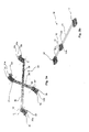
Fig. 1 gezeigte Ausführungsform in einer zeichnerisch modifizierten Variante, wobei die Lager stark schematisch und vereinfacht dargestellt sind; - Figur 3a
- eine Detailansicht der in der
Fig. 2 gezeigten Führungsschere in einer perspektivischen Seitenansicht; und - Figur 3b
- eine Detailansicht einer der in der
Fig. 2 gezeigten Lagervorrichtungen in einer perspektivischen Seitenansicht.
- FIG. 1
- a side perspective view of a parallel-Ausstellfenster or a parallel-issuing door with a frame and a wing with a guide scissors according to a preferred embodiment of the invention, wherein the guide scissors is coupled to the frame and the wing in each case to a bearing device according to a preferred embodiment of the invention ;
- FIG. 2
- in the
Fig. 1 embodiment shown in a graphically modified variant, the bearings are shown very schematically and simplified; - FIG. 3a
- a detailed view of the in the
Fig. 2 Guide shears shown in a perspective side view; and - FIG. 3b
- a detail view of one of the
Fig. 2 shown storage devices in a perspective side view.
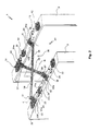
In der
Die Lagerböcke 12, 22 können so wie dargestellt zweiteilig ausgeführt sein, insbesondere aus einem Oberteil mit einer Standard-Höhe, welche in Bezug auf den Durchmesser der Lagerachse 11, 21 ausgelegt sein kann, sowie einem Unterteil mit variabler Höhe, über welches der Abstand der Lagerachse von der Oberfläche des Flügels bzw. Rahmens eingestellt werden kann, je nachdem in welchem Ausmaß eine Schwenkbewegung erwünscht ist. Hierdurch kann der für den gesamten Mechanismus erforderliche Platzbedarf minimiert werden. Die Lagerböcke 12, 22 können aber auch einteilig aufgebaut sein, insbesondere auch mit einer Standard-Höhe, unabhängig davon ob die Durchführung 12b, 22b für die Lagerachse 11, 21 in dem jeweiligen Lagerbock 12, 22 in einer Standard-Höhe oder in einer variablen Höhe angeordnet werden kann.The bearing blocks 12, 22 can be designed as shown in two parts, in particular from an upper part with a standard height, which may be designed in relation to the diameter of the bearing
Die Führungsschere 30 ist über vier Schwenklager 31, 32, 33, 34 zu den Lagervorrichtungen 10, 20 gekoppelt, insbesondere zu jeder Lagervorrichtung 10, 20 jeweils über ein erstes bzw. zweites festes Schwenklager 31, 32 und ein erstes bzw. zweites verschiebbares Schwenklager 33, 34. An den festen Schwenklagern 31, 32 sind jeweils Feststellmittel 31 a, 32a zum Fixieren der festen Schwenklager 31, 32 an den Lagerachsen 11, 21 vorgesehen, und an den verschiebbaren Schwenklagern 33, 34 sind jeweils Bremsmittel 33a, 34a zum Einstellen einer Reibkraft bzw. Bremskraft zwischen den verschiebbaren Schwenklagern 33, 34 und den Lagerachsen 11, 21. Die verschiebbaren Schwenklagern 33, 34 sind entlang der jeweiligen Lagerachse 11, 21 in Richtung des jeweiligen Doppelpfeils verschiebbar, also vor und zurück, und über die Bremsmittel 33a, 34a können sie einstellbar gebremst ausgeführt sein. Die Schwenklager 31, 32, 33, 34 sind an freien Enden von Scherenarmen 35, 36 der Führungsschere 30 vorgesehen, welche über ein Scherengelenk 38 zueinander gekoppelt sind. In den Schwenklagern 31, 32, 33, 34 ist jeweils eine Durchführung 39 vorgesehen, durch welche die Lagerachse 11, 21 geführt werden kann, so dass die Schwenklager 31, 32, 33, 34 auf einfache und robuste Weise entlang der Lagerachsen 11, 21 geführt werden können. Die Scherenarme 35, 36 sind gegenüber den Schwenklagern 31, 32, 33, 34 drehbar um eine z-Achse gelagert, insbesondere über einen Bolzen 37, welcher durch Seitenplatten der Schwenklager 31, 32, 33, 34 geführt bzw. gehalten ist.The guide shears 30 is coupled via four
Die Schwenklager 31, 32, 33, 34 sind zweckdienlicher Weise in einer Richtung senkrecht zu den Lagerachsen 11, 21 mit einer Breite ausgeführt, die größer ist als eine Breite der Lagerböcke 12, 22. Als Breite ist dabei insbesondere die Ausdehnung der Schwenklager 31, 32, 33, 34 bzw. Lagerböcke 12, 22 zwischen einer zum Scherengelenk 38 weisenden Seite der Schwenklager 31, 32, 33, 34 bzw. Lagerböcke 12, 22 und der jeweiligen Durchführung 12b, 22b, 39 für die Lagerachse 11, 21 zu verstehen. Mit anderen Worten entspricht die Breite der Erstreckung senkrecht zur Lagerachse 11, 12. Hierdurch können die Scherenarme 35, 36 in einer geschlossenen Stellung der Führungsschere 30 an den mittleren Lagerböcken 12, 22 zur Anlage gebracht werden. Insbesondere sind die Drehlager bzw. Bolzen 37 der Schwenklager 31, 32, 33, 34 in einem Abstand zu der jeweiligen Lagerachse 11, 21 angeordnet, welcher mindestens um die halbe Breite der Scherenarme 35, 36 größer ist als der Abstand zwischen einer zum Scherengelenk 38 weisenden Seite der Lagerböcke 12, 22 und der Lagerachse 11, 21.The
Die Durchführung 12b, 22b in den mittleren Lagerböcken 12, 22 ist jeweils bevorzugt als eine zylindrische durchgehenden Durchführung, insbesondere als eine Durchgangsbohrung ausgebildet, so dass eine einzige Lagerachse alle drei Lagerböcke miteinander verbinden kann und der mittlere Lagerbock 12, 22 entlang der Lagerachse bei der Montage frei positioniert werden kann. Auf diese Weise kann die maximale durch die Führungsschere 30 zugelassene Öffnung des Flügels 3 gegenüber dem Rahmen 2 auf flexible und einfache Weise auch durch einen Endverbraucher festgelegt werden. Die gesamte Montage des Führungssystems 40 ist äußerst simpel, da lediglich die Lagerböcke 12, 22 an Rahmen 2 und Flügel 3 montiert, insbesondere angeschraubt, werden müssen, insbesondere nachdem die jeweilige Lagerachse 11, 21 durch die Durchführungen 12b, 22b der Lagerböcke 12, 22 geführt wurde und die Schwenklager 31, 32, 33, 34 zwischen den Lagerböcken 12, 22 vorgesehen wurden. Dabei können die Scherenarme 35, 36 bereits an die Schwenklager 31, 32, 33, 34 gekoppelt sein oder nach der Montage der Lagerböcke 12, 22 auf Rahmen 2 und Flügel 3 mit den Schwenklagern 31, 32, 33, 34 gekoppelt werden, insbesondere jeweils über den Bolzen 37, welcher z.B. einen eigenen Sicherungsstift aufweisen kann oder auch über einen herkömmlichen Splint an den Schwenklagern 31, 32, 33, 34 gesichert werden kann.The
Die Führungsschere 30 und die Lagervorrichtungen 10, 20 können zusammen ein Führungssystem 40 bilden, weiches in Bezug auf eine durch das Scherengelenk 38 verlaufende Symmetrieebene S symmetrisch ausgebildet ist. Es ist zu erwähnen, dass in
In der
Die
- 11
- Fenster oder TürWindow or door
- 22
- Rahmenframe
- 33
- Flügelwing
- 1010
- erste Lagervorrichtungfirst storage device
- 1111
- erste Lagerachsefirst bearing axis
- 1212
- Lagerbock für erste LagerachseBearing block for first bearing axle
- 12a12a
- Anschlag am LagerbockStop on the bearing block
- 12b12b
- Durchführung am LagerbockExecution on the bearing block
- 2020
- zweite Lagervorrichtungsecond storage device
- 2121
- zweite Lagerachsesecond bearing axis
- 2222
- Lagerbock für zweite LagerachseBearing block for second bearing axle
- 22a22a
- Anschlag am LagerbockStop on the bearing block
- 22b22b
- Durchführung am LagerbockExecution on the bearing block
- 3030
- Führungsschereleadership scissors
- 3131
- erstes festes Schwenklagerfirst fixed pivot bearing
- 31a31a
- FeststellmittelLocking means
- 3232
- zweites festes Schwenklagersecond fixed pivot bearing
- 32a32a
- FeststellmittelLocking means
- 3333
- erstes verschiebbares Schwenklagerfirst sliding pivot bearing
- 33a33a
- Bremsmittelbraking means
- 3434
- zweites verschiebbares Schwenklagersecond sliding pivot bearing
- 34a34a
- Bremsmittelbraking means
- 3535
- erster Scherenarmfirst scissor arm
- 3636
- zweiter Scherenarmsecond scissor arm
- 3737
- Bolzenbolt
- 3838
- Scherengelenkscissor joint
- 3939
- Durchführungexecution
- 4040
- Führungssystem bestehend aus Führungsschere und LagervorrichtungenGuiding system consisting of guide shears and storage devices
- SS
- Symmetrieebeneplane of symmetry
- zz
- Drehachse um welche der Scherenarm drehen kannRotary axis around which the scissor arm can rotate
Claims (14)
dadurch gekennzeichnet, dass die Scherenarme (35, 36) jeweils mindestens ein Schwenklager (31, 32, 33, 34) aufweisen, über welches die Scherenarme (35, 36) schwenkbar lagerbar sind.A four-point guide shears (30) for parallel-view windows or doors constructed from a frame (2) and a sash (3), said guide shear (30) having a first scissor arm (35) and a second scissor arm (36), respectively in two on the frame (2) and the wing (3) arranged bearings are rotatably storable and in each case in one of the bearings are additionally axially displaceable storable,
characterized in that the scissor arms (35, 36) each have at least one pivot bearing (31, 32, 33, 34), via which the scissor arms (35, 36) are pivotally storable.
dadurch gekennzeichnet, dass die Lagervorrichtung (10, 20) eine Lagerachse (11, 21) aufweist, welche dazu ausgebildet ist, zwei Schwenklager (31, 32, 33, 34) schwenkbar um die Lagerachse (11, 21) und eines der Schwenklager (33, 34) axial verschiebbar an der Lagerachse (11, 21) zu lagern.Bearing device (10, 20) for parallel-opening windows or doors with a frame (2) and a wing (3), wherein the bearing device (10, 20) is adapted to a first scissor arm (35) and a second scissor arm (36 ) rotatably support and one of the scissor arms (35, 36) to store axially displaceable,
characterized in that the bearing device (10, 20) has a bearing axis (11, 21) which is designed to pivot two pivot bearings (31, 32, 33, 34) about the bearing axis (11, 21) and one of the pivot bearings (11). 33, 34) axially slidably to the bearing axis (11, 21) to store.
Priority Applications (1)
| Application Number | Priority Date | Filing Date | Title |
|---|---|---|---|
| PL13003991T PL2696018T3 (en) | 2012-08-10 | 2013-08-09 | Pivotable guiding scissors, bearing device and guidance system for parallel vent window |
Applications Claiming Priority (1)
| Application Number | Priority Date | Filing Date | Title |
|---|---|---|---|
| DE202012007652U DE202012007652U1 (en) | 2012-08-10 | 2012-08-10 | Swiveling guide shears, storage device and guide system for parallel opening window |
Publications (3)
| Publication Number | Publication Date |
|---|---|
| EP2696018A2 true EP2696018A2 (en) | 2014-02-12 |
| EP2696018A3 EP2696018A3 (en) | 2014-12-17 |
| EP2696018B1 EP2696018B1 (en) | 2017-03-01 |
Family
ID=47019957
Family Applications (1)
| Application Number | Title | Priority Date | Filing Date |
|---|---|---|---|
| EP13003991.0A Active EP2696018B1 (en) | 2012-08-10 | 2013-08-09 | Pivotable guiding scissors, bearing device and guidance system for parallel vent window |
Country Status (4)
| Country | Link |
|---|---|
| EP (1) | EP2696018B1 (en) |
| DE (1) | DE202012007652U1 (en) |
| ES (1) | ES2622500T3 (en) |
| PL (1) | PL2696018T3 (en) |
Cited By (1)
| Publication number | Priority date | Publication date | Assignee | Title |
|---|---|---|---|---|
| CN114215439A (en) * | 2021-11-22 | 2022-03-22 | 北京木易东方科技有限公司 | Horizontal-pushing hinge and window |
Families Citing this family (2)
| Publication number | Priority date | Publication date | Assignee | Title |
|---|---|---|---|---|
| CN203267243U (en) * | 2013-03-18 | 2013-11-06 | 鸿准精密模具(昆山)有限公司 | Laminating device |
| FR3032992B1 (en) * | 2015-02-19 | 2017-11-17 | Laurent Poupar | STORAGE SPACE CLOSURE DEVICE AND STORAGE SYSTEM COMPRISING SAME |
Citations (2)
| Publication number | Priority date | Publication date | Assignee | Title |
|---|---|---|---|---|
| DE10031820A1 (en) | 2000-06-30 | 2002-01-10 | Winkhaus Fa August | Opening arrangement for window casement or door-leaf has arm swiveling by means of swivel axles on frame and leaf/casement, with drive unit and transmission element |
| DE102008032750B4 (en) | 2008-07-11 | 2011-05-05 | Josef Gartner Gmbh | parallel opening |
Family Cites Families (3)
| Publication number | Priority date | Publication date | Assignee | Title |
|---|---|---|---|---|
| GB453688A (en) * | 1936-01-11 | 1936-09-16 | Leslie Schofield | Improvements in or relating to ventilator window or the like opening and closing mechanism |
| GB2436122B (en) * | 2006-03-16 | 2011-05-11 | Securistyle Ltd | A parallel hinge with drive mechanism |
| US8758012B2 (en) | 2008-07-14 | 2014-06-24 | Nobel Biocare Services Ag | Compact dental implant |
-
2012
- 2012-08-10 DE DE202012007652U patent/DE202012007652U1/en not_active Expired - Lifetime
-
2013
- 2013-08-09 EP EP13003991.0A patent/EP2696018B1/en active Active
- 2013-08-09 PL PL13003991T patent/PL2696018T3/en unknown
- 2013-08-09 ES ES13003991.0T patent/ES2622500T3/en active Active
Patent Citations (2)
| Publication number | Priority date | Publication date | Assignee | Title |
|---|---|---|---|---|
| DE10031820A1 (en) | 2000-06-30 | 2002-01-10 | Winkhaus Fa August | Opening arrangement for window casement or door-leaf has arm swiveling by means of swivel axles on frame and leaf/casement, with drive unit and transmission element |
| DE102008032750B4 (en) | 2008-07-11 | 2011-05-05 | Josef Gartner Gmbh | parallel opening |
Cited By (2)
| Publication number | Priority date | Publication date | Assignee | Title |
|---|---|---|---|---|
| CN114215439A (en) * | 2021-11-22 | 2022-03-22 | 北京木易东方科技有限公司 | Horizontal-pushing hinge and window |
| CN114215439B (en) * | 2021-11-22 | 2023-03-10 | 北京木易东方科技有限公司 | Horizontal push hinge and window |
Also Published As
| Publication number | Publication date |
|---|---|
| DE202012007652U1 (en) | 2012-09-18 |
| EP2696018A3 (en) | 2014-12-17 |
| EP2696018B1 (en) | 2017-03-01 |
| ES2622500T3 (en) | 2017-07-06 |
| PL2696018T3 (en) | 2017-08-31 |
Similar Documents
| Publication | Publication Date | Title |
|---|---|---|
| EP0297202B1 (en) | Check for a sliding door, movable out of a plane into a parallel plane | |
| EP3980619B1 (en) | Piece of furniture having a door held by a translation device | |
| DE202012002502U1 (en) | Device for assisting and facilitating the tilting opening and closing of a window or a door | |
| DE202006003177U1 (en) | Hardware for windows or doors | |
| EP2696018B1 (en) | Pivotable guiding scissors, bearing device and guidance system for parallel vent window | |
| DE202012002741U1 (en) | Fitting for an at least approximately parallel storable and horizontally movable in this Parallelabstelllage wings of windows or doors | |
| EP3034731B1 (en) | Fitting for windows and doors | |
| EP3168398A1 (en) | Hidden hinge for doors, windows or similar components | |
| EP3749822B1 (en) | Assisting fitting for a tiltable wing of a window or door | |
| DE102011085177A1 (en) | Drive system for roof system of motor car, has safety devices comprising stop surfaces displaced against each other during arrangement of carriage outside of safety position such that surfaces are bypassed together during movement of arm | |
| EP1605125A2 (en) | Guiding system for guiding sliding doors or sliding windows | |
| EP2540616A2 (en) | Closing mechanism for a sliding door that closes with power assistance | |
| EP2495382A2 (en) | Device for moving a leaf of a window, door or similar | |
| EP2754815A2 (en) | Tilt fitting for wing of a window or a door | |
| DE102015225655B4 (en) | Window sill and window equipped with it | |
| EP1852567B1 (en) | Carriage | |
| EP2677100A2 (en) | Sliding door assembly | |
| EP2677101A2 (en) | Automatic sliding door system | |
| EP1757765B1 (en) | Fine-framed door | |
| DE102014202797B3 (en) | spacer | |
| EP2369111B1 (en) | Corner bearing for concealed assembly | |
| DE102014209915B3 (en) | Adjustable vertical stiffener with backdrop for a removable wing of a window or door | |
| DE3911187A1 (en) | Lifting/tilting window | |
| DE1584084A1 (en) | Opening device for tilt and turn windows | |
| EP2481874B1 (en) | Turn-tilt fitting |
Legal Events
| Date | Code | Title | Description |
|---|---|---|---|
| AK | Designated contracting states |
Kind code of ref document: A2 Designated state(s): AL AT BE BG CH CY CZ DE DK EE ES FI FR GB GR HR HU IE IS IT LI LT LU LV MC MK MT NL NO PL PT RO RS SE SI SK SM TR |
|
| AX | Request for extension of the european patent |
Extension state: BA ME |
|
| PUAI | Public reference made under article 153(3) epc to a published international application that has entered the european phase |
Free format text: ORIGINAL CODE: 0009012 |
|
| PUAL | Search report despatched |
Free format text: ORIGINAL CODE: 0009013 |
|
| AK | Designated contracting states |
Kind code of ref document: A3 Designated state(s): AL AT BE BG CH CY CZ DE DK EE ES FI FR GB GR HR HU IE IS IT LI LT LU LV MC MK MT NL NO PL PT RO RS SE SI SK SM TR |
|
| AX | Request for extension of the european patent |
Extension state: BA ME |
|
| RIC1 | Information provided on ipc code assigned before grant |
Ipc: E05D 15/30 20060101ALI20141107BHEP Ipc: E05D 15/34 20060101AFI20141107BHEP |
|
| 17P | Request for examination filed |
Effective date: 20150617 |
|
| RBV | Designated contracting states (corrected) |
Designated state(s): AL AT BE BG CH CY CZ DE DK EE ES FI FR GB GR HR HU IE IS IT LI LT LU LV MC MK MT NL NO PL PT RO RS SE SI SK SM TR |
|
| 17Q | First examination report despatched |
Effective date: 20160420 |
|
| GRAP | Despatch of communication of intention to grant a patent |
Free format text: ORIGINAL CODE: EPIDOSNIGR1 |
|
| INTG | Intention to grant announced |
Effective date: 20161128 |
|
| GRAS | Grant fee paid |
Free format text: ORIGINAL CODE: EPIDOSNIGR3 |
|
| GRAA | (expected) grant |
Free format text: ORIGINAL CODE: 0009210 |
|
| AK | Designated contracting states |
Kind code of ref document: B1 Designated state(s): AL AT BE BG CH CY CZ DE DK EE ES FI FR GB GR HR HU IE IS IT LI LT LU LV MC MK MT NL NO PL PT RO RS SE SI SK SM TR |
|
| REG | Reference to a national code |
Ref country code: GB Ref legal event code: FG4D Free format text: NOT ENGLISH |
|
| REG | Reference to a national code |
Ref country code: CH Ref legal event code: EP Ref country code: AT Ref legal event code: REF Ref document number: 871561 Country of ref document: AT Kind code of ref document: T Effective date: 20170315 |
|
| REG | Reference to a national code |
Ref country code: IE Ref legal event code: FG4D Free format text: LANGUAGE OF EP DOCUMENT: GERMAN |
|
| RAP2 | Party data changed (patent owner data changed or rights of a patent transferred) |
Owner name: WILH. SCHLECHTENDAHL & SOEHNE GMBH & CO. KG |
|
| REG | Reference to a national code |
Ref country code: DE Ref legal event code: R096 Ref document number: 502013006486 Country of ref document: DE |
|
| REG | Reference to a national code |
Ref country code: NL Ref legal event code: MP Effective date: 20170301 |
|
| REG | Reference to a national code |
Ref country code: ES Ref legal event code: FG2A Ref document number: 2622500 Country of ref document: ES Kind code of ref document: T3 Effective date: 20170706 |
|
| REG | Reference to a national code |
Ref country code: LT Ref legal event code: MG4D |
|
| PG25 | Lapsed in a contracting state [announced via postgrant information from national office to epo] |
Ref country code: FI Free format text: LAPSE BECAUSE OF FAILURE TO SUBMIT A TRANSLATION OF THE DESCRIPTION OR TO PAY THE FEE WITHIN THE PRESCRIBED TIME-LIMIT Effective date: 20170301 Ref country code: HR Free format text: LAPSE BECAUSE OF FAILURE TO SUBMIT A TRANSLATION OF THE DESCRIPTION OR TO PAY THE FEE WITHIN THE PRESCRIBED TIME-LIMIT Effective date: 20170301 Ref country code: GR Free format text: LAPSE BECAUSE OF FAILURE TO SUBMIT A TRANSLATION OF THE DESCRIPTION OR TO PAY THE FEE WITHIN THE PRESCRIBED TIME-LIMIT Effective date: 20170602 Ref country code: LT Free format text: LAPSE BECAUSE OF FAILURE TO SUBMIT A TRANSLATION OF THE DESCRIPTION OR TO PAY THE FEE WITHIN THE PRESCRIBED TIME-LIMIT Effective date: 20170301 Ref country code: NO Free format text: LAPSE BECAUSE OF FAILURE TO SUBMIT A TRANSLATION OF THE DESCRIPTION OR TO PAY THE FEE WITHIN THE PRESCRIBED TIME-LIMIT Effective date: 20170601 |
|
| REG | Reference to a national code |
Ref country code: FR Ref legal event code: PLFP Year of fee payment: 5 |
|
| PG25 | Lapsed in a contracting state [announced via postgrant information from national office to epo] |
Ref country code: SE Free format text: LAPSE BECAUSE OF FAILURE TO SUBMIT A TRANSLATION OF THE DESCRIPTION OR TO PAY THE FEE WITHIN THE PRESCRIBED TIME-LIMIT Effective date: 20170301 Ref country code: BG Free format text: LAPSE BECAUSE OF FAILURE TO SUBMIT A TRANSLATION OF THE DESCRIPTION OR TO PAY THE FEE WITHIN THE PRESCRIBED TIME-LIMIT Effective date: 20170601 Ref country code: LV Free format text: LAPSE BECAUSE OF FAILURE TO SUBMIT A TRANSLATION OF THE DESCRIPTION OR TO PAY THE FEE WITHIN THE PRESCRIBED TIME-LIMIT Effective date: 20170301 Ref country code: RS Free format text: LAPSE BECAUSE OF FAILURE TO SUBMIT A TRANSLATION OF THE DESCRIPTION OR TO PAY THE FEE WITHIN THE PRESCRIBED TIME-LIMIT Effective date: 20170301 |
|
| PG25 | Lapsed in a contracting state [announced via postgrant information from national office to epo] |
Ref country code: NL Free format text: LAPSE BECAUSE OF FAILURE TO SUBMIT A TRANSLATION OF THE DESCRIPTION OR TO PAY THE FEE WITHIN THE PRESCRIBED TIME-LIMIT Effective date: 20170301 |
|
| PG25 | Lapsed in a contracting state [announced via postgrant information from national office to epo] |
Ref country code: EE Free format text: LAPSE BECAUSE OF FAILURE TO SUBMIT A TRANSLATION OF THE DESCRIPTION OR TO PAY THE FEE WITHIN THE PRESCRIBED TIME-LIMIT Effective date: 20170301 Ref country code: RO Free format text: LAPSE BECAUSE OF FAILURE TO SUBMIT A TRANSLATION OF THE DESCRIPTION OR TO PAY THE FEE WITHIN THE PRESCRIBED TIME-LIMIT Effective date: 20170301 Ref country code: CZ Free format text: LAPSE BECAUSE OF FAILURE TO SUBMIT A TRANSLATION OF THE DESCRIPTION OR TO PAY THE FEE WITHIN THE PRESCRIBED TIME-LIMIT Effective date: 20170301 Ref country code: SK Free format text: LAPSE BECAUSE OF FAILURE TO SUBMIT A TRANSLATION OF THE DESCRIPTION OR TO PAY THE FEE WITHIN THE PRESCRIBED TIME-LIMIT Effective date: 20170301 |
|
| PG25 | Lapsed in a contracting state [announced via postgrant information from national office to epo] |
Ref country code: SM Free format text: LAPSE BECAUSE OF FAILURE TO SUBMIT A TRANSLATION OF THE DESCRIPTION OR TO PAY THE FEE WITHIN THE PRESCRIBED TIME-LIMIT Effective date: 20170301 Ref country code: IS Free format text: LAPSE BECAUSE OF FAILURE TO SUBMIT A TRANSLATION OF THE DESCRIPTION OR TO PAY THE FEE WITHIN THE PRESCRIBED TIME-LIMIT Effective date: 20170701 Ref country code: PT Free format text: LAPSE BECAUSE OF FAILURE TO SUBMIT A TRANSLATION OF THE DESCRIPTION OR TO PAY THE FEE WITHIN THE PRESCRIBED TIME-LIMIT Effective date: 20170703 |
|
| REG | Reference to a national code |
Ref country code: DE Ref legal event code: R097 Ref document number: 502013006486 Country of ref document: DE |
|
| PLBE | No opposition filed within time limit |
Free format text: ORIGINAL CODE: 0009261 |
|
| STAA | Information on the status of an ep patent application or granted ep patent |
Free format text: STATUS: NO OPPOSITION FILED WITHIN TIME LIMIT |
|
| PG25 | Lapsed in a contracting state [announced via postgrant information from national office to epo] |
Ref country code: DK Free format text: LAPSE BECAUSE OF FAILURE TO SUBMIT A TRANSLATION OF THE DESCRIPTION OR TO PAY THE FEE WITHIN THE PRESCRIBED TIME-LIMIT Effective date: 20170301 |
|
| 26N | No opposition filed |
Effective date: 20171204 |
|
| PG25 | Lapsed in a contracting state [announced via postgrant information from national office to epo] |
Ref country code: SI Free format text: LAPSE BECAUSE OF FAILURE TO SUBMIT A TRANSLATION OF THE DESCRIPTION OR TO PAY THE FEE WITHIN THE PRESCRIBED TIME-LIMIT Effective date: 20170301 |
|
| PG25 | Lapsed in a contracting state [announced via postgrant information from national office to epo] |
Ref country code: MC Free format text: LAPSE BECAUSE OF FAILURE TO SUBMIT A TRANSLATION OF THE DESCRIPTION OR TO PAY THE FEE WITHIN THE PRESCRIBED TIME-LIMIT Effective date: 20170301 |
|
| REG | Reference to a national code |
Ref country code: IE Ref legal event code: MM4A |
|
| PG25 | Lapsed in a contracting state [announced via postgrant information from national office to epo] |
Ref country code: LU Free format text: LAPSE BECAUSE OF NON-PAYMENT OF DUE FEES Effective date: 20170809 |
|
| PG25 | Lapsed in a contracting state [announced via postgrant information from national office to epo] |
Ref country code: IE Free format text: LAPSE BECAUSE OF NON-PAYMENT OF DUE FEES Effective date: 20170809 |
|
| REG | Reference to a national code |
Ref country code: FR Ref legal event code: PLFP Year of fee payment: 6 |
|
| PG25 | Lapsed in a contracting state [announced via postgrant information from national office to epo] |
Ref country code: MT Free format text: LAPSE BECAUSE OF FAILURE TO SUBMIT A TRANSLATION OF THE DESCRIPTION OR TO PAY THE FEE WITHIN THE PRESCRIBED TIME-LIMIT Effective date: 20170301 |
|
| PG25 | Lapsed in a contracting state [announced via postgrant information from national office to epo] |
Ref country code: HU Free format text: LAPSE BECAUSE OF FAILURE TO SUBMIT A TRANSLATION OF THE DESCRIPTION OR TO PAY THE FEE WITHIN THE PRESCRIBED TIME-LIMIT; INVALID AB INITIO Effective date: 20130809 |
|
| PG25 | Lapsed in a contracting state [announced via postgrant information from national office to epo] |
Ref country code: CY Free format text: LAPSE BECAUSE OF NON-PAYMENT OF DUE FEES Effective date: 20170301 |
|
| PG25 | Lapsed in a contracting state [announced via postgrant information from national office to epo] |
Ref country code: MK Free format text: LAPSE BECAUSE OF FAILURE TO SUBMIT A TRANSLATION OF THE DESCRIPTION OR TO PAY THE FEE WITHIN THE PRESCRIBED TIME-LIMIT Effective date: 20170301 |
|
| PG25 | Lapsed in a contracting state [announced via postgrant information from national office to epo] |
Ref country code: AL Free format text: LAPSE BECAUSE OF FAILURE TO SUBMIT A TRANSLATION OF THE DESCRIPTION OR TO PAY THE FEE WITHIN THE PRESCRIBED TIME-LIMIT Effective date: 20170301 |
|
| P01 | Opt-out of the competence of the unified patent court (upc) registered |
Effective date: 20230613 |
|
| PGFP | Annual fee paid to national office [announced via postgrant information from national office to epo] |
Ref country code: TR Payment date: 20230808 Year of fee payment: 11 Ref country code: IT Payment date: 20230825 Year of fee payment: 11 Ref country code: GB Payment date: 20230822 Year of fee payment: 11 Ref country code: CH Payment date: 20230902 Year of fee payment: 11 Ref country code: AT Payment date: 20230822 Year of fee payment: 11 |
|
| PGFP | Annual fee paid to national office [announced via postgrant information from national office to epo] |
Ref country code: PL Payment date: 20230727 Year of fee payment: 11 Ref country code: FR Payment date: 20230824 Year of fee payment: 11 Ref country code: DE Payment date: 20230821 Year of fee payment: 11 Ref country code: BE Payment date: 20230821 Year of fee payment: 11 |
|
| PGFP | Annual fee paid to national office [announced via postgrant information from national office to epo] |
Ref country code: ES Payment date: 20231027 Year of fee payment: 11 |