EP2696018A2 - Compas pivotant, dispositif de logement et système de guidage pour fenêtre basculante parallèle - Google Patents
Compas pivotant, dispositif de logement et système de guidage pour fenêtre basculante parallèle Download PDFInfo
- Publication number
- EP2696018A2 EP2696018A2 EP13003991.0A EP13003991A EP2696018A2 EP 2696018 A2 EP2696018 A2 EP 2696018A2 EP 13003991 A EP13003991 A EP 13003991A EP 2696018 A2 EP2696018 A2 EP 2696018A2
- Authority
- EP
- European Patent Office
- Prior art keywords
- bearing
- frame
- wing
- pivot
- pivot bearings
- Prior art date
- Legal status (The legal status is an assumption and is not a legal conclusion. Google has not performed a legal analysis and makes no representation as to the accuracy of the status listed.)
- Granted
Links
- 238000006073 displacement reaction Methods 0.000 claims abstract description 6
- 238000010276 construction Methods 0.000 abstract description 5
- 230000008901 benefit Effects 0.000 description 3
- 230000008878 coupling Effects 0.000 description 3
- 238000010168 coupling process Methods 0.000 description 3
- 238000005859 coupling reaction Methods 0.000 description 3
- 239000000463 material Substances 0.000 description 2
- 230000007246 mechanism Effects 0.000 description 2
- 230000008859 change Effects 0.000 description 1
- 230000003750 conditioning effect Effects 0.000 description 1
- 238000013016 damping Methods 0.000 description 1
- 238000011161 development Methods 0.000 description 1
- 230000018109 developmental process Effects 0.000 description 1
- 238000004519 manufacturing process Methods 0.000 description 1
- 230000004048 modification Effects 0.000 description 1
- 238000012986 modification Methods 0.000 description 1
- 239000007779 soft material Substances 0.000 description 1
- 239000011122 softwood Substances 0.000 description 1
- 239000007787 solid Substances 0.000 description 1
- 239000011343 solid material Substances 0.000 description 1
Images

Classifications
-
- E—FIXED CONSTRUCTIONS
- E05—LOCKS; KEYS; WINDOW OR DOOR FITTINGS; SAFES
- E05D—HINGES OR SUSPENSION DEVICES FOR DOORS, WINDOWS OR WINGS
- E05D15/00—Suspension arrangements for wings
- E05D15/28—Suspension arrangements for wings supported on arms movable in horizontal plane
- E05D15/32—Suspension arrangements for wings supported on arms movable in horizontal plane with two pairs of pivoted arms
- E05D15/34—Suspension arrangements for wings supported on arms movable in horizontal plane with two pairs of pivoted arms with wings opening parallel to themselves
-
- E—FIXED CONSTRUCTIONS
- E05—LOCKS; KEYS; WINDOW OR DOOR FITTINGS; SAFES
- E05D—HINGES OR SUSPENSION DEVICES FOR DOORS, WINDOWS OR WINGS
- E05D15/00—Suspension arrangements for wings
- E05D15/28—Suspension arrangements for wings supported on arms movable in horizontal plane
- E05D15/30—Suspension arrangements for wings supported on arms movable in horizontal plane with pivoted arms and sliding guides
-
- E—FIXED CONSTRUCTIONS
- E05—LOCKS; KEYS; WINDOW OR DOOR FITTINGS; SAFES
- E05Y—INDEXING SCHEME ASSOCIATED WITH SUBCLASSES E05D AND E05F, RELATING TO CONSTRUCTION ELEMENTS, ELECTRIC CONTROL, POWER SUPPLY, POWER SIGNAL OR TRANSMISSION, USER INTERFACES, MOUNTING OR COUPLING, DETAILS, ACCESSORIES, AUXILIARY OPERATIONS NOT OTHERWISE PROVIDED FOR, APPLICATION THEREOF
- E05Y2600/00—Mounting or coupling arrangements for elements provided for in this subclass
- E05Y2600/10—Adjustable
- E05Y2600/30—Adjustment motion
- E05Y2600/32—Rotary motion
- E05Y2600/322—Rotary motion around a horizontal axis
Definitions
- the invention relates to fittings and bearings for windows or doors, in particular guide / Ausstellscheren for parallel issuing window or door wings against a frame.
- a wing arranged in a window frame can in many cases only be arranged laterally offset parallel to the frame when opening, so that the wing is only connected to the frame via fittings and no longer bears against one of the frame sides.
- An additional angular arrangement can only be provided when a plurality of fittings are used, namely at least four fittings, and on each fitting further, the distance between the frame and wing is freely adjustable. Then, at two of the four fittings, a first distance and at the other two of the four fittings, a second distance can be adjusted, and the wing is arranged at an angle to the frame.
- Ausstelischeren or guide shears as a special form of fittings are used to keep windows in a tilted position and in most cases to move from a closed position to the tilted position and vice versa. They usually have both functions.
- guide shears is used, as it emphasizes that a guide when opening or closing the windows is desired.
- Guide shears can be provided laterally on the window frame and / or on the horizontally extending upper window frame part.
- two types can be distinguished, namely three-point guide shears and four-point guide shears. Both types each have two scissor arms, which are coupled together.
- three-point guide shears usually two of the three bearing points are rotatably mounted and one rotatable and displaceable.
- two bearing points are rotatably and slidably mounted.
- the scissor arms are coupled together in a bearing, which in addition to a rotation and a translational relative movement allows each other, for example, a slot.
- four-point guide shears usually two of the four bearing points are rotatably mounted and the other two rotatable and displaceable.
- the scissor arms are coupled together in a bearing, which only allows rotation to each other.
- the publication EP 2 228 509 A1 shows a display device for a window or a door and has a stay, which is pivotally mounted on a tilting wing about a horizontal axis parallel to the wing.
- the publication DE 100 31 820 A1 shows a tilting device for a tilting wing and has a stay arm, which is pivotally mounted on a frame and a wing about a vertical axis, wherein in a tilted position both pivot axes are inclined from the vertical position.
- the publication DE 10 2008 032 750 B4 shows a Parallelausstellpper which supports a window sash over a plurality of fittings, each with a lever arm and a support arm and an X-scissors with a pair of scissor arms on a window frame, the scissor arms are rotatably mounted respectively in two bearings on the sash and the window frame and one of the bearings also allows axial displacement.
- Each scissor arm is slidable on one side and fixed on one side between the sash and the frame.
- the task is to provide a simply constructed guide shears for a wide range of applications.
- a four-point guide shears according to the invention for constructed from a frame and a wing parallel-Ausstellpper or doors has a first scissor arm and a second scissor arm, which are each rotatably storable in two arranged on the frame and the wing bearings and each in one of the camp are additionally axially displaceable storable.
- at least one pivot bearing is provided on each of the scissor arms, via which the scissor arms are pivotably mountable.
- a four-point guide shears thus has scissor arms, each with at least one bearing, in which in addition to a rotational movement, a pivoting movement and optionally also a translational movement can take place.
- the pivot bearings are bearings with three degrees of freedom.
- a pivot bearing is designed as a radial sliding bearing on each scissor arm, which additionally allows a rotational movement of the scissor arm relative to the pivot bearing.
- two pivot bearings are preferably provided on the scissor arms, by means of which the scissor arms are pivotally mountable in each case in both bearings, i. over which both free ends of the scissor arms are pivotally storable.
- Such a parallel Ausstellmechanimus with four-point guide scissors can also be used in folding windows or doors.
- the Parallel Ausstellmechanimus can allow a variety of different arrangements of a wing over a frame.
- An inventive Four-point guide scissors with pivot bearings is also designed to exhibit a wing of a parallel-Ausstellppers or a parallel-issuing door at an angle relative to the frame, wherein the wing with respect to the frame can be pivoted upwards or upwards.
- a good lateral stability can be ensured in a flared wing, in particular by the lateral support is carried out substantially solely by the cross-shaped scissor arms in a symmetrical manner on wings and frame and in relatively widely spaced bearing points.
- an opening limitation on the guide shears can be done, in particular by the pivot bearings are arranged between bearing blocks on which they can strike when they are arranged in a desired position corresponding to the desired maximum open position. It can also provide an opening angle limitation, in particular by providing a stop on the pivot bearings which strikes against a corresponding stop when pivoting has taken place by a certain angle.
- the scissor arms of a four-point guide scissors according to the invention are not only one-sided displaceable and fixed on one side fixed to the frame and wings, but are also pivotable, in particular about a bearing axis on which the scissor arms are also mounted axially displaceable.
- a pivoting movement is preferably to be understood a rotational movement, which takes place about an axis which is aligned horizontally in an arrangement of four-point guide scissors on a horizontally oriented side of a wing or frame, so that the four-point guide shear against the Wing or frame can pivot, even if the distance between the wing and frame remains constant.
- the pivot bearings may be rotatable, e.g. allow about an axis along which usually two of the four free ends of the four-point guide shears are displaced.
- a rotational movement is to be understood preferably a rotary movement, which takes place about an axis in an arrangement of the four-point guide shears on a horizontally oriented side of a Wing or frame is oriented substantially vertically, so that the four-point guide shear can rotate relative to the wing or frame to change the distance between the wing and frame. That is, the pivot bearings allow the four-point guide shears per se required relative rotation between the scissor arms and the bearing points.
- a four-point guide shear with which the wing can be arranged in a variety of different positions relative to the frame, and at the same time a high stability of the flared wing and a good ruggedness of the bearings or the whole deployment mechanism can be ensured ,
- the guide shear according to the invention can combine several functions in itself, it is simple. In particular, it may be constructed symmetrically, wherein the plane of symmetry passes through a scissors joint, via which the two scissor arms are coupled together.
- a guide scissors according to the invention can be used for parallel-lowering opening window and for parallel lifting-Ausstellpper. It can also be used for countersunk folding windows and lifting / tilting windows. This results in a wide field of application.
- the pivot bearings are adapted to be pivotally mounted about a bearing axis.
- the pivot bearings may each have a passage, which is designed to be arranged around a bearing axis and guided by the bearing axis.
- the implementation may be designed as a cylindrical bore, in particular as a bore, which is introduced into a solid part of the pivot bearing. It can optionally also be formed by a tube which is connected to one or two side plates, in which a bolt may be provided for coupling the scissor arm to the pivot bearing.
- the implementation can be designed as a smooth slide bearing from a smooth running plain bearing material with a low coefficient of friction.
- the pivot bearings may optionally have one or two side plates, via which they are coupled to the respective scissor arm.
- both scissor arms each have two pivot bearings, wherein each scissor arm one of the pivot bearing is designed as a fixed pivot bearing and the other of the pivot bearing as a sliding pivot bearing.
- the pivot bearings can also be designed to rotatably support the scissor arms. In this way, in a pivot bearing, the storage about a rotational axis, the storage about a pivot axis and the storage along a translational axis take place.
- a fixed pivot bearing or fixed pivot bearing is preferably a pivot bearing to understand, which can be fixed to a bearing axis.
- a sliding pivot bearing is preferably a pivot bearing to understand, which can be moved along which it is pivotable along a bearing axis.
- the fixed pivot bearings may be formed as fixed pivot bearings in that they have locking means over which they are e.g. ascertainable on a bearing axis in a certain position, i. can be fixed.
- the displaceable pivot bearings are slidably formed on the bearing axis, by which they are also pivotable.
- This can be realized via pivot bearings, which have a passage for the bearing axis and a sandwich-like slot guide, wherein the slot guide are provided to guide the free ends of the scissor arms laterally and support.
- the passage can be arranged in a kind of sleeve, and on the sleeve can protrude two side plates, between which a free end of a scissor arm can be performed.
- the pivot bearing may have a rectangular base surface in a plan view, and describe in a side view a U-shaped outer contour, wherein the legs of the U correspond to the two side plates and the rounding of the U of the outer surface of the sleeve.
- At least one of the displaceable pivot bearing is adjustable braked in the direction of displacement is executed.
- the displacement direction preferably corresponds to an orientation of a bearing axis on which the pivot bearings can be mounted.
- a pivot bearing which is braked in the direction of displacement or completely blocked, be converted from a radial sliding bearing in a radial-axial bearing (Radiaxiager), which also allows the rotation between the pivot bearing and scissor arm (degree of freedom 2 instead of 3).
- the displaceable pivot bearings may have as a braking means, for example, a screw with a flat bottom or a wedge displaceable in the direction of a bearing axis, and the braking means can be adjusted on the one hand with regard to a preferred friction between the pivot bearing and the bearing axis, on the other hand as a fixation in serve a certain position and thus the determination of a certain distance or angle of the wing relative to the frame.
- the displaceable pivot bearings may also have an additional bushing, which can be pressed by a braking means to the bearing axis.
- a wing By adjustable braked pivot bearing a wing can be stored insensitive to wind. A hitting the wing in the wind can be easily prevented and adapted to the local weather conditions. It is e.g. possible to store the wing stably in any position relative to the frame stable.
- the fixed pivot bearings have locking means for fixing the fixed pivot bearings to a bearing axle.
- the fixed pivot bearings may be e.g. be fixable on a bearing axis.
- the locking means can be designed as guided in an internal thread on the respective fixed pivot bearing locking screws which are screwed into the bearing axis, or they can be designed as connected to the respective fixed pivot bearing clamping rings.
- the pivot bearings are each coupled via a bolt to the scissor arms, wherein the bolt is formed as a rotation axis about which the pivot bearings are rotatably storable. This allows a simple and robust coupling between scissor arms, pivot bearings and frame or wing done.
- the bearing device is designed for parallel-opening windows or doors with a frame and a wing designed to rotatably support a first scissor arm and a second scissor arm and axially slidably support one of the scissor arms, wherein the bearing device has a bearing axis, which is formed , Two pivot bearings pivotally mounted about the bearing axis and one of the pivot bearings axially displaceable on the bearing axis.
- the bearing device may also provide the pivot bearings themselves, if the pivot bearings are not already provided on scissor arms of a guide shear.
- a bearing axis is preferably an element or a component to understand, which can be arranged parallel to the surface of a frame or wing and serves to store both scissor arms on the frame or the wing.
- a bearing axis may e.g. designed as a tube or rod made of solid material, in particular of a material having a smooth surface with a low coefficient of friction.
- the bearing axis can also be integrated into a rail or a part, in particular structural part, of the frame or wing.
- the bearing axis is designed as a pipe or rod and mounted in three bearing blocks, particularly preferably continuously in a middle bearing block and in blind holes in bearing blocks at their free ends.
- the bearing axis may be mounted on a bearing block, which is fixedly connected to the frame or the wing.
- the bracket may be glued or screwed to the frame or wing or fastened at an angle or strap.
- the bearing block on two through holes, so that the bearing block in a simple manner rotatably mounted on the frame or wing can be mounted and the bearing axis in a certain orientation.
- the bearing axis is mounted on three bearing blocks, wherein two of the three bearing blocks are arranged at free ends of the bearing axis and the other bearing block in a position on the bearing axis, in which the wing in a maximum open position is arranged to the frame when a pivot bearing comes to bear on the bearing block.
- the bearing block has a passage in which the bearing axis is mounted.
- the passageway is disposed on a side of the bearing block which faces away from scissor arms to connect the sash to the frame when mounted on the sash or frame.
- a guide system according to claim 11, namely a guide system for guiding parallel opening windows or doors constructed from a frame and a wing, wherein it is preferably proposed that two be at least approximately identical in construction and at least approximately symmetrically arranged bearing devices according to the invention are provided, which are coupled to a four-point guide scissors according to the invention.
- the displaceable pivot bearings are each mounted between two bearing blocks of the bearing device.
- the bearing blocks may each have a stop or a stop surface against which the sliding pivot bearing can strike when the wing is opened or closed.
- About the pedestals can thus define the maximum opening of the wing and also the position of the wing on the frame in which the wing is to be closed with the frame. This can avoid that wing and frame hard hit each other when the operation is careless or the wing is detected by a gust of wind.
- the stop or the abutment surface can be designed for this purpose optionally made of a damping or soft material, at least in one layer on the bearing block. This is useful even if the frame, e.g. made of a soft wood, to avoid that the bearing blocks are beaten from their brackets over time.
- the bearing blocks are arranged so that the sliding pivot bearings abut the bearing blocks when the wing is opposite the frame in a closed position or in a maximum open position.
- bushings for the bearing axis are provided on the bearing blocks, and indeed a side facing away from the window or door opening, ie outside the guide system.
- two bearing devices according to the invention are provided with three bearing blocks, wherein the bearing blocks each having a passage, which are arranged on a side facing away from the scissor arms of the guide shears side of the bearing blocks, and wherein the Implementation relative to a base of the bearing blocks, with which the bearing blocks are mounted on the wing or frame, is arranged elevated and at each bearing device, the pivot bearings are pivotable in both directions about the bearing axis.
- the guide system can be used both in parallel lowering and parallel lifting-Ausstellppern or doors.
- the pivot bearings Due to the spaced arrangements of the bearing axes of the wing or frame, the pivot bearings can pivot in a large angular range about the bearing axes, without colliding with the wing or frame.
- the maximum possible pivoting angle can be in the range of 10 to 60 degrees, preferably 20 to 50 degrees, more preferably 30 to 40 degrees.
- a swivel angle over 45 degrees is not required in many cases, so that the arrangement of the bearing axis and the bearing blocks and the design of the pivot bearing, for. also with regard to an inconspicuous arrangement or a low height or a small footprint can be done.
- the entire guide system can be constructed symmetrically, wherein the plane of symmetry passes through a scissor joint, via which the two scissor arms of the four-point guide shears are coupled together.
- the symmetry can be given regardless of the arrangement of the wing relative to the frame.
- the plane of symmetry extends in the open by pivoted wing through the scissors joint and is also inclined relative to the frame or wing by the same extent as the scissor arms, so that the scissor arms perpendicular to the Stay aligned with the symmetry plane.
- the symmetry can be given at least in relation to the bearing axis and the arrangement of the bearing blocks and the pivot bearings. Due to the symmetrical structure, for example, the advantage of a simple assembly. Also, the total number of different components is very low, which allows a cost-effective production, especially due to higher number of pieces of each part.
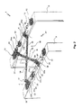
- a parallel-Ausstellmutmuttant or a parallel-issuing door with a frame 2 and a wing 3 is shown, wherein the wing 3 is arranged at a distance from the frame 2 and is mounted on the frame 2 via a guide shears 30.
- a first bearing device 10 with a first bearing axis 11 and three bearing blocks 12, each with a stop 12a, here in the form of one of the side surfaces of the bearing blocks 12, and a respective passage 12b for performing the bearing axis 11 is provided.
- a corresponding second bearing device 20 with a second bearing axis 21 and three bearing blocks 22, each with a stop 22a, analogously in the form of one of the side surfaces of the bearing blocks 22, and a respective passage 22b for performing the bearing axis 21.
- the bearing blocks 12, 22 can be designed as shown in two parts, in particular from an upper part with a standard height, which may be designed in relation to the diameter of the bearing axis 11, 21, and a lower part with variable height, over which the distance of the Bearing axis of the surface of the wing or frame can be adjusted, depending on the extent to which a pivoting movement is desired. As a result, the required space for the entire mechanism space can be minimized.
- the bearing blocks 12, 22 may also be constructed in one piece, in particular with a standard height, regardless of whether the passage 12b, 22b for the bearing axis 11, 21 in the respective bearing block 12, 22 in a standard height or in a variable Height can be arranged.
- the guide shears 30 is coupled via four pivot bearings 31, 32, 33, 34 to the bearing devices 10, 20, in particular to each bearing device 10, 20 respectively via a first and second fixed pivot bearings 31, 32 and a first and second sliding pivot bearing 33rd , 34.
- On the fixed pivot bearings 31, 32 are each locking means 31 a, 32 a for fixing the fixed pivot bearings 31, 32 provided on the bearing shafts 11, 21, and at The displaceable pivot bearings 33, 34 are respectively braking means 33a, 34a for adjusting a frictional force or braking force between the displaceable pivot bearings 33, 34 and the bearing shafts 11, 21.
- the displaceable pivot bearings 33, 34 are along the respective bearing axis 11, 21 in the direction of slidable respective double arrow, ie back and forth, and via the braking means 33a, 34a they can be made adjustable braked executed.
- the pivot bearings 31, 32, 33, 34 are provided at free ends of scissor arms 35, 36 of the guide shears 30, which are coupled to one another via a scissors joint 38.
- In the pivot bearings 31, 32, 33, 34 each have a passage 39 is provided, through which the bearing axis 11, 21 can be performed so that the pivot bearings 31, 32, 33, 34 in a simple and robust manner along the bearing axes 11, 21st can be performed.
- the scissor arms 35, 36 are mounted relative to the pivot bearings 31, 32, 33, 34 rotatably about a z-axis, in particular via a bolt 37, which is guided or held by side plates of the pivot bearings 31, 32, 33, 34.
- the pivot bearings 31, 32, 33, 34 are expediently designed in a direction perpendicular to the bearing shafts 11, 21 with a width that is greater than a width of the bearing blocks 12, 22.
- width is in particular the extension of the pivot bearing 31, 32, 33, 34 and bearing blocks 12, 22 between a side facing the scissors hinge 38 side of the pivot bearings 31, 32, 33, 34 and bearing blocks 12, 22 and the respective passage 12b, 22b, 39 for the bearing axis 11, 21 to understand ,
- the width of the extension is perpendicular to the bearing axis 11, 12. This allows the scissor arms 35, 36 are brought in a closed position of the guide shears 30 to the middle bearing blocks 12, 22 for conditioning.
- pivot bearings or bolts 37 of the pivot bearings 31, 32, 33, 34 are arranged at a distance from the respective bearing axis 11, 21, which is greater than the distance between a scissors joint 38 at least half the width of the scissor arms 35, 36 facing side of the bearing blocks 12, 22 and the bearing axis 11, 21st
- the passage 12b, 22b in the middle bearing blocks 12, 22 is in each case preferably designed as a cylindrical through-passage, in particular as a through-bore, so that a single bearing axis all three bearing blocks can connect to each other and the middle bracket 12, 22 along the bearing axis during assembly can be freely positioned. In this way, the maximum permitted by the guide scissors 30 opening of the wing 3 relative to the frame 2 in a flexible and simple manner can also be determined by an end user.
- the entire assembly of the guide system 40 is extremely simple, since only the bearing blocks 12, 22 mounted on frame 2 and wing 3, in particular screwed, must be, in particular after the respective bearing axis 11, 21 through the bushings 12 b, 22 b of the bearing blocks 12, 22nd was guided and the pivot bearings 31, 32, 33, 34 were provided between the bearing blocks 12, 22.
- the scissor arms 35, 36 may already be coupled to the pivot bearings 31, 32, 33, 34 or after assembly of the bearing blocks 12, 22 on frame 2 and wing 3 with the pivot bearings 31, 32, 33, 34 coupled, in particular in each case via the bolt 37, which may for example have its own safety pin or can be secured by a conventional cotter pin on the pivot bearings 31, 32, 33, 34.
- the guide shears 30 and the bearing devices 10, 20 can together form a guide system 40, which is formed symmetrically with respect to a plane of symmetry S extending through the scissors joint 38. It should be mentioned that in Fig. 1 Strictly speaking, the position of the displaceable pivot bearings 33, 34 would have to be shown further away from the right bearing block of each bearing axis and closer to the middle bearing block of each bearing axis, because the middle bearing block is that bearing block on which the displaceable pivot bearings 33, 34 in an open position to rest can or should come.
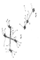
- FIG. 2 are essentially the ones in FIG. 1 already shown components in a slight modification and shown schematically, also to better illustrate the arrangement of the sliding pivot bearings 33, 34 with respect to the bearing blocks 12, 22.
- the guide shears 40 is as in FIG. 1 shown in a half-open position, in which the wing 3 is not yet arranged in a maximum open position, in particular because the pivot bearings 33, 34 are not yet applied to the middle bearing blocks 12, 22.
- the Fig. 3a shows the guide shear 30 decoupled from storage devices.
- the pivot bearings 31, 32, 33, 34 are provided, which can each be coupled to an axis of bearing devices before a complete guide system is mounted on a frame or wing.
- the Fig. 3b shows the storage device 10 decoupled from a guide scissors.
- the axis 11 is guided in bushings 12b through the bearing blocks 12, which have for this purpose bushings 12b, which may be performed in the outer bearing blocks 12, for example, as blind holes.
Landscapes
- Engineering & Computer Science (AREA)
- Mechanical Engineering (AREA)
- Hinges (AREA)
- Wing Frames And Configurations (AREA)
- Specific Sealing Or Ventilating Devices For Doors And Windows (AREA)
Priority Applications (1)
| Application Number | Priority Date | Filing Date | Title |
|---|---|---|---|
| PL13003991T PL2696018T3 (pl) | 2012-08-10 | 2013-08-09 | Wychylne nożyce prowadzące, mechanizm łożyskowy oraz system prowadnic do okien równolegle odstawnych |
Applications Claiming Priority (1)
| Application Number | Priority Date | Filing Date | Title |
|---|---|---|---|
| DE202012007652U DE202012007652U1 (de) | 2012-08-10 | 2012-08-10 | Schwenkbare Führungsschere, Lagervorrichtung sowie Führungssystem für Parallel-Ausstellfenster |
Publications (3)
| Publication Number | Publication Date |
|---|---|
| EP2696018A2 true EP2696018A2 (fr) | 2014-02-12 |
| EP2696018A3 EP2696018A3 (fr) | 2014-12-17 |
| EP2696018B1 EP2696018B1 (fr) | 2017-03-01 |
Family
ID=47019957
Family Applications (1)
| Application Number | Title | Priority Date | Filing Date |
|---|---|---|---|
| EP13003991.0A Active EP2696018B1 (fr) | 2012-08-10 | 2013-08-09 | Compas pivotant, dispositif de logement et système de guidage pour fenêtre basculante parallèle |
Country Status (4)
| Country | Link |
|---|---|
| EP (1) | EP2696018B1 (fr) |
| DE (1) | DE202012007652U1 (fr) |
| ES (1) | ES2622500T3 (fr) |
| PL (1) | PL2696018T3 (fr) |
Cited By (1)
| Publication number | Priority date | Publication date | Assignee | Title |
|---|---|---|---|---|
| CN114215439A (zh) * | 2021-11-22 | 2022-03-22 | 北京木易东方科技有限公司 | 一种平推铰链及窗户 |
Families Citing this family (2)
| Publication number | Priority date | Publication date | Assignee | Title |
|---|---|---|---|---|
| CN203267243U (zh) * | 2013-03-18 | 2013-11-06 | 鸿准精密模具(昆山)有限公司 | 压合装置 |
| FR3032992B1 (fr) * | 2015-02-19 | 2017-11-17 | Laurent Poupar | Dispositif de fermeture d’espace de rangement et systeme de rangement le comprenant |
Citations (2)
| Publication number | Priority date | Publication date | Assignee | Title |
|---|---|---|---|---|
| DE10031820A1 (de) | 2000-06-30 | 2002-01-10 | Winkhaus Fa August | Ausstellvorrichtung für einen an einem Rahmen schwenkbar angebrachten Kipp- oder Dreh-Kipp-Flügel |
| DE102008032750B4 (de) | 2008-07-11 | 2011-05-05 | Josef Gartner Gmbh | Parallelausstellfenster |
Family Cites Families (3)
| Publication number | Priority date | Publication date | Assignee | Title |
|---|---|---|---|---|
| GB453688A (en) * | 1936-01-11 | 1936-09-16 | Leslie Schofield | Improvements in or relating to ventilator window or the like opening and closing mechanism |
| GB2436122B (en) * | 2006-03-16 | 2011-05-11 | Securistyle Ltd | A parallel hinge with drive mechanism |
| US8758012B2 (en) | 2008-07-14 | 2014-06-24 | Nobel Biocare Services Ag | Compact dental implant |
-
2012
- 2012-08-10 DE DE202012007652U patent/DE202012007652U1/de not_active Expired - Lifetime
-
2013
- 2013-08-09 ES ES13003991.0T patent/ES2622500T3/es active Active
- 2013-08-09 EP EP13003991.0A patent/EP2696018B1/fr active Active
- 2013-08-09 PL PL13003991T patent/PL2696018T3/pl unknown
Patent Citations (2)
| Publication number | Priority date | Publication date | Assignee | Title |
|---|---|---|---|---|
| DE10031820A1 (de) | 2000-06-30 | 2002-01-10 | Winkhaus Fa August | Ausstellvorrichtung für einen an einem Rahmen schwenkbar angebrachten Kipp- oder Dreh-Kipp-Flügel |
| DE102008032750B4 (de) | 2008-07-11 | 2011-05-05 | Josef Gartner Gmbh | Parallelausstellfenster |
Cited By (2)
| Publication number | Priority date | Publication date | Assignee | Title |
|---|---|---|---|---|
| CN114215439A (zh) * | 2021-11-22 | 2022-03-22 | 北京木易东方科技有限公司 | 一种平推铰链及窗户 |
| CN114215439B (zh) * | 2021-11-22 | 2023-03-10 | 北京木易东方科技有限公司 | 一种平推铰链及窗户 |
Also Published As
| Publication number | Publication date |
|---|---|
| PL2696018T3 (pl) | 2017-08-31 |
| DE202012007652U1 (de) | 2012-09-18 |
| EP2696018A3 (fr) | 2014-12-17 |
| EP2696018B1 (fr) | 2017-03-01 |
| ES2622500T3 (es) | 2017-07-06 |
Similar Documents
| Publication | Publication Date | Title |
|---|---|---|
| EP0297202B1 (fr) | Bras de compas pour fenêtre coulissante se déplaçant dans un plan parallèle | |
| EP3980619B1 (fr) | Meuble comprenant une porte tenue par un dispositif de déplacement | |
| DE202012002502U1 (de) | Vorrichtung zur Unterstützung und Erleichterung des Kipp-Öffnens und -Schließens für ein Fenster oder eine Tür | |
| DE202006003177U1 (de) | Beschlag für Fenster oder Türen | |
| EP2696018B1 (fr) | Compas pivotant, dispositif de logement et système de guidage pour fenêtre basculante parallèle | |
| DE202012002741U1 (de) | Beschlag für einen zumindest annähernd parallel abstellbaren und in dieser Parallelabstelllage horizontal verschiebbaren Flügel von Fenstern oder Türen | |
| DE3605637A1 (de) | Beschlag fuer einen schrank mit hochschwenkbarer tuer | |
| EP3034731B1 (fr) | Ferrure de fenêtres et portes | |
| EP3168398A1 (fr) | Charnière dissimulée pour portes, fenêtres ou composants similaires | |
| EP3749822B1 (fr) | Ferrure d'appui pour un battant basculant d'une fenêtre ou d'une porte | |
| DE102011085177A1 (de) | Antriebssystem für ein KFZ-Dachsystem | |
| EP2540616A2 (fr) | Mécanisme de fermeture pour portes coulissantes assistées | |
| EP2495382A2 (fr) | Dispositif de déplacement d'un battant d'une fenêtre, d'une porte ou analogue | |
| EP2754815A2 (fr) | Ferrure de basculement pour un vantail de fenêtre ou de porte | |
| DE102015225655B4 (de) | Fensterbrett und damit ausgestattetes Fenster | |
| EP1852567B1 (fr) | Chariot | |
| EP2677100A2 (fr) | Installation de porte coulissante | |
| EP2677101A2 (fr) | Installation de porte coulissante automatique | |
| EP1757765B1 (fr) | Porte avec cadre étroit | |
| DE102014202797B3 (de) | Distanzhalter | |
| EP2369111B1 (fr) | Palier d'angle caché | |
| DE102014209915B3 (de) | Einstellbare Vertikalaussteifung mit Kulisse für einen abstellbaren Flügel eines Fensters oder einer Tür | |
| DE3911187A1 (de) | Hebekippfenster | |
| DE1584084A1 (de) | Ausstellvorrichtung fuer Drehkippfenster | |
| EP2481874B1 (fr) | Ferrure oscillo-battante |
Legal Events
| Date | Code | Title | Description |
|---|---|---|---|
| AK | Designated contracting states |
Kind code of ref document: A2 Designated state(s): AL AT BE BG CH CY CZ DE DK EE ES FI FR GB GR HR HU IE IS IT LI LT LU LV MC MK MT NL NO PL PT RO RS SE SI SK SM TR |
|
| AX | Request for extension of the european patent |
Extension state: BA ME |
|
| PUAI | Public reference made under article 153(3) epc to a published international application that has entered the european phase |
Free format text: ORIGINAL CODE: 0009012 |
|
| PUAL | Search report despatched |
Free format text: ORIGINAL CODE: 0009013 |
|
| AK | Designated contracting states |
Kind code of ref document: A3 Designated state(s): AL AT BE BG CH CY CZ DE DK EE ES FI FR GB GR HR HU IE IS IT LI LT LU LV MC MK MT NL NO PL PT RO RS SE SI SK SM TR |
|
| AX | Request for extension of the european patent |
Extension state: BA ME |
|
| RIC1 | Information provided on ipc code assigned before grant |
Ipc: E05D 15/30 20060101ALI20141107BHEP Ipc: E05D 15/34 20060101AFI20141107BHEP |
|
| 17P | Request for examination filed |
Effective date: 20150617 |
|
| RBV | Designated contracting states (corrected) |
Designated state(s): AL AT BE BG CH CY CZ DE DK EE ES FI FR GB GR HR HU IE IS IT LI LT LU LV MC MK MT NL NO PL PT RO RS SE SI SK SM TR |
|
| 17Q | First examination report despatched |
Effective date: 20160420 |
|
| GRAP | Despatch of communication of intention to grant a patent |
Free format text: ORIGINAL CODE: EPIDOSNIGR1 |
|
| INTG | Intention to grant announced |
Effective date: 20161128 |
|
| GRAS | Grant fee paid |
Free format text: ORIGINAL CODE: EPIDOSNIGR3 |
|
| GRAA | (expected) grant |
Free format text: ORIGINAL CODE: 0009210 |
|
| AK | Designated contracting states |
Kind code of ref document: B1 Designated state(s): AL AT BE BG CH CY CZ DE DK EE ES FI FR GB GR HR HU IE IS IT LI LT LU LV MC MK MT NL NO PL PT RO RS SE SI SK SM TR |
|
| REG | Reference to a national code |
Ref country code: GB Ref legal event code: FG4D Free format text: NOT ENGLISH |
|
| REG | Reference to a national code |
Ref country code: CH Ref legal event code: EP Ref country code: AT Ref legal event code: REF Ref document number: 871561 Country of ref document: AT Kind code of ref document: T Effective date: 20170315 |
|
| REG | Reference to a national code |
Ref country code: IE Ref legal event code: FG4D Free format text: LANGUAGE OF EP DOCUMENT: GERMAN |
|
| RAP2 | Party data changed (patent owner data changed or rights of a patent transferred) |
Owner name: WILH. SCHLECHTENDAHL & SOEHNE GMBH & CO. KG |
|
| REG | Reference to a national code |
Ref country code: DE Ref legal event code: R096 Ref document number: 502013006486 Country of ref document: DE |
|
| REG | Reference to a national code |
Ref country code: NL Ref legal event code: MP Effective date: 20170301 |
|
| REG | Reference to a national code |
Ref country code: ES Ref legal event code: FG2A Ref document number: 2622500 Country of ref document: ES Kind code of ref document: T3 Effective date: 20170706 |
|
| REG | Reference to a national code |
Ref country code: LT Ref legal event code: MG4D |
|
| PG25 | Lapsed in a contracting state [announced via postgrant information from national office to epo] |
Ref country code: FI Free format text: LAPSE BECAUSE OF FAILURE TO SUBMIT A TRANSLATION OF THE DESCRIPTION OR TO PAY THE FEE WITHIN THE PRESCRIBED TIME-LIMIT Effective date: 20170301 Ref country code: HR Free format text: LAPSE BECAUSE OF FAILURE TO SUBMIT A TRANSLATION OF THE DESCRIPTION OR TO PAY THE FEE WITHIN THE PRESCRIBED TIME-LIMIT Effective date: 20170301 Ref country code: GR Free format text: LAPSE BECAUSE OF FAILURE TO SUBMIT A TRANSLATION OF THE DESCRIPTION OR TO PAY THE FEE WITHIN THE PRESCRIBED TIME-LIMIT Effective date: 20170602 Ref country code: LT Free format text: LAPSE BECAUSE OF FAILURE TO SUBMIT A TRANSLATION OF THE DESCRIPTION OR TO PAY THE FEE WITHIN THE PRESCRIBED TIME-LIMIT Effective date: 20170301 Ref country code: NO Free format text: LAPSE BECAUSE OF FAILURE TO SUBMIT A TRANSLATION OF THE DESCRIPTION OR TO PAY THE FEE WITHIN THE PRESCRIBED TIME-LIMIT Effective date: 20170601 |
|
| REG | Reference to a national code |
Ref country code: FR Ref legal event code: PLFP Year of fee payment: 5 |
|
| PG25 | Lapsed in a contracting state [announced via postgrant information from national office to epo] |
Ref country code: SE Free format text: LAPSE BECAUSE OF FAILURE TO SUBMIT A TRANSLATION OF THE DESCRIPTION OR TO PAY THE FEE WITHIN THE PRESCRIBED TIME-LIMIT Effective date: 20170301 Ref country code: BG Free format text: LAPSE BECAUSE OF FAILURE TO SUBMIT A TRANSLATION OF THE DESCRIPTION OR TO PAY THE FEE WITHIN THE PRESCRIBED TIME-LIMIT Effective date: 20170601 Ref country code: LV Free format text: LAPSE BECAUSE OF FAILURE TO SUBMIT A TRANSLATION OF THE DESCRIPTION OR TO PAY THE FEE WITHIN THE PRESCRIBED TIME-LIMIT Effective date: 20170301 Ref country code: RS Free format text: LAPSE BECAUSE OF FAILURE TO SUBMIT A TRANSLATION OF THE DESCRIPTION OR TO PAY THE FEE WITHIN THE PRESCRIBED TIME-LIMIT Effective date: 20170301 |
|
| PG25 | Lapsed in a contracting state [announced via postgrant information from national office to epo] |
Ref country code: NL Free format text: LAPSE BECAUSE OF FAILURE TO SUBMIT A TRANSLATION OF THE DESCRIPTION OR TO PAY THE FEE WITHIN THE PRESCRIBED TIME-LIMIT Effective date: 20170301 |
|
| PG25 | Lapsed in a contracting state [announced via postgrant information from national office to epo] |
Ref country code: EE Free format text: LAPSE BECAUSE OF FAILURE TO SUBMIT A TRANSLATION OF THE DESCRIPTION OR TO PAY THE FEE WITHIN THE PRESCRIBED TIME-LIMIT Effective date: 20170301 Ref country code: RO Free format text: LAPSE BECAUSE OF FAILURE TO SUBMIT A TRANSLATION OF THE DESCRIPTION OR TO PAY THE FEE WITHIN THE PRESCRIBED TIME-LIMIT Effective date: 20170301 Ref country code: CZ Free format text: LAPSE BECAUSE OF FAILURE TO SUBMIT A TRANSLATION OF THE DESCRIPTION OR TO PAY THE FEE WITHIN THE PRESCRIBED TIME-LIMIT Effective date: 20170301 Ref country code: SK Free format text: LAPSE BECAUSE OF FAILURE TO SUBMIT A TRANSLATION OF THE DESCRIPTION OR TO PAY THE FEE WITHIN THE PRESCRIBED TIME-LIMIT Effective date: 20170301 |
|
| PG25 | Lapsed in a contracting state [announced via postgrant information from national office to epo] |
Ref country code: SM Free format text: LAPSE BECAUSE OF FAILURE TO SUBMIT A TRANSLATION OF THE DESCRIPTION OR TO PAY THE FEE WITHIN THE PRESCRIBED TIME-LIMIT Effective date: 20170301 Ref country code: IS Free format text: LAPSE BECAUSE OF FAILURE TO SUBMIT A TRANSLATION OF THE DESCRIPTION OR TO PAY THE FEE WITHIN THE PRESCRIBED TIME-LIMIT Effective date: 20170701 Ref country code: PT Free format text: LAPSE BECAUSE OF FAILURE TO SUBMIT A TRANSLATION OF THE DESCRIPTION OR TO PAY THE FEE WITHIN THE PRESCRIBED TIME-LIMIT Effective date: 20170703 |
|
| REG | Reference to a national code |
Ref country code: DE Ref legal event code: R097 Ref document number: 502013006486 Country of ref document: DE |
|
| PLBE | No opposition filed within time limit |
Free format text: ORIGINAL CODE: 0009261 |
|
| STAA | Information on the status of an ep patent application or granted ep patent |
Free format text: STATUS: NO OPPOSITION FILED WITHIN TIME LIMIT |
|
| PG25 | Lapsed in a contracting state [announced via postgrant information from national office to epo] |
Ref country code: DK Free format text: LAPSE BECAUSE OF FAILURE TO SUBMIT A TRANSLATION OF THE DESCRIPTION OR TO PAY THE FEE WITHIN THE PRESCRIBED TIME-LIMIT Effective date: 20170301 |
|
| 26N | No opposition filed |
Effective date: 20171204 |
|
| PG25 | Lapsed in a contracting state [announced via postgrant information from national office to epo] |
Ref country code: SI Free format text: LAPSE BECAUSE OF FAILURE TO SUBMIT A TRANSLATION OF THE DESCRIPTION OR TO PAY THE FEE WITHIN THE PRESCRIBED TIME-LIMIT Effective date: 20170301 |
|
| PG25 | Lapsed in a contracting state [announced via postgrant information from national office to epo] |
Ref country code: MC Free format text: LAPSE BECAUSE OF FAILURE TO SUBMIT A TRANSLATION OF THE DESCRIPTION OR TO PAY THE FEE WITHIN THE PRESCRIBED TIME-LIMIT Effective date: 20170301 |
|
| REG | Reference to a national code |
Ref country code: IE Ref legal event code: MM4A |
|
| PG25 | Lapsed in a contracting state [announced via postgrant information from national office to epo] |
Ref country code: LU Free format text: LAPSE BECAUSE OF NON-PAYMENT OF DUE FEES Effective date: 20170809 |
|
| PG25 | Lapsed in a contracting state [announced via postgrant information from national office to epo] |
Ref country code: IE Free format text: LAPSE BECAUSE OF NON-PAYMENT OF DUE FEES Effective date: 20170809 |
|
| REG | Reference to a national code |
Ref country code: FR Ref legal event code: PLFP Year of fee payment: 6 |
|
| PG25 | Lapsed in a contracting state [announced via postgrant information from national office to epo] |
Ref country code: MT Free format text: LAPSE BECAUSE OF FAILURE TO SUBMIT A TRANSLATION OF THE DESCRIPTION OR TO PAY THE FEE WITHIN THE PRESCRIBED TIME-LIMIT Effective date: 20170301 |
|
| PG25 | Lapsed in a contracting state [announced via postgrant information from national office to epo] |
Ref country code: HU Free format text: LAPSE BECAUSE OF FAILURE TO SUBMIT A TRANSLATION OF THE DESCRIPTION OR TO PAY THE FEE WITHIN THE PRESCRIBED TIME-LIMIT; INVALID AB INITIO Effective date: 20130809 |
|
| PG25 | Lapsed in a contracting state [announced via postgrant information from national office to epo] |
Ref country code: CY Free format text: LAPSE BECAUSE OF NON-PAYMENT OF DUE FEES Effective date: 20170301 |
|
| PG25 | Lapsed in a contracting state [announced via postgrant information from national office to epo] |
Ref country code: MK Free format text: LAPSE BECAUSE OF FAILURE TO SUBMIT A TRANSLATION OF THE DESCRIPTION OR TO PAY THE FEE WITHIN THE PRESCRIBED TIME-LIMIT Effective date: 20170301 |
|
| PG25 | Lapsed in a contracting state [announced via postgrant information from national office to epo] |
Ref country code: AL Free format text: LAPSE BECAUSE OF FAILURE TO SUBMIT A TRANSLATION OF THE DESCRIPTION OR TO PAY THE FEE WITHIN THE PRESCRIBED TIME-LIMIT Effective date: 20170301 |
|
| P01 | Opt-out of the competence of the unified patent court (upc) registered |
Effective date: 20230613 |
|
| PGFP | Annual fee paid to national office [announced via postgrant information from national office to epo] |
Ref country code: TR Payment date: 20230808 Year of fee payment: 11 Ref country code: IT Payment date: 20230825 Year of fee payment: 11 Ref country code: GB Payment date: 20230822 Year of fee payment: 11 Ref country code: CH Payment date: 20230902 Year of fee payment: 11 Ref country code: AT Payment date: 20230822 Year of fee payment: 11 |
|
| PGFP | Annual fee paid to national office [announced via postgrant information from national office to epo] |
Ref country code: PL Payment date: 20230727 Year of fee payment: 11 Ref country code: FR Payment date: 20230824 Year of fee payment: 11 Ref country code: DE Payment date: 20230821 Year of fee payment: 11 Ref country code: BE Payment date: 20230821 Year of fee payment: 11 |
|
| PGFP | Annual fee paid to national office [announced via postgrant information from national office to epo] |
Ref country code: ES Payment date: 20231027 Year of fee payment: 11 |