EP2692570B1 - Fahrzeuginterne ladevorrichtung - Google Patents
Fahrzeuginterne ladevorrichtung Download PDFInfo
- Publication number
- EP2692570B1 EP2692570B1 EP12762866.7A EP12762866A EP2692570B1 EP 2692570 B1 EP2692570 B1 EP 2692570B1 EP 12762866 A EP12762866 A EP 12762866A EP 2692570 B1 EP2692570 B1 EP 2692570B1
- Authority
- EP
- European Patent Office
- Prior art keywords
- vehicle
- information
- vehicle information
- plc communication
- control section
- Prior art date
- Legal status (The legal status is an assumption and is not a legal conclusion. Google has not performed a legal analysis and makes no representation as to the accuracy of the status listed.)
- Active
Links
- 238000004891 communication Methods 0.000 claims description 128
- 230000005540 biological transmission Effects 0.000 claims description 86
- 238000011156 evaluation Methods 0.000 claims description 37
- 238000001514 detection method Methods 0.000 claims description 25
- 230000005856 abnormality Effects 0.000 claims description 7
- 230000015556 catabolic process Effects 0.000 claims description 4
- 230000009467 reduction Effects 0.000 claims description 3
- 238000012423 maintenance Methods 0.000 claims description 2
- 238000000034 method Methods 0.000 description 98
- 230000008569 process Effects 0.000 description 90
- 238000010586 diagram Methods 0.000 description 10
- 238000012544 monitoring process Methods 0.000 description 4
- 230000008878 coupling Effects 0.000 description 3
- 238000010168 coupling process Methods 0.000 description 3
- 238000005859 coupling reaction Methods 0.000 description 3
- 238000003745 diagnosis Methods 0.000 description 3
- 230000007246 mechanism Effects 0.000 description 3
- 230000008901 benefit Effects 0.000 description 2
- 230000000052 comparative effect Effects 0.000 description 2
- 230000005611 electricity Effects 0.000 description 2
- 238000003032 molecular docking Methods 0.000 description 2
- 230000000903 blocking effect Effects 0.000 description 1
- 230000008859 change Effects 0.000 description 1
- 230000007423 decrease Effects 0.000 description 1
- 230000001419 dependent effect Effects 0.000 description 1
- 230000000694 effects Effects 0.000 description 1
- 230000007257 malfunction Effects 0.000 description 1
- 230000003287 optical effect Effects 0.000 description 1
Images


Classifications
-
- B—PERFORMING OPERATIONS; TRANSPORTING
- B60—VEHICLES IN GENERAL
- B60L—PROPULSION OF ELECTRICALLY-PROPELLED VEHICLES; SUPPLYING ELECTRIC POWER FOR AUXILIARY EQUIPMENT OF ELECTRICALLY-PROPELLED VEHICLES; ELECTRODYNAMIC BRAKE SYSTEMS FOR VEHICLES IN GENERAL; MAGNETIC SUSPENSION OR LEVITATION FOR VEHICLES; MONITORING OPERATING VARIABLES OF ELECTRICALLY-PROPELLED VEHICLES; ELECTRIC SAFETY DEVICES FOR ELECTRICALLY-PROPELLED VEHICLES
- B60L53/00—Methods of charging batteries, specially adapted for electric vehicles; Charging stations or on-board charging equipment therefor; Exchange of energy storage elements in electric vehicles
- B60L53/10—Methods of charging batteries, specially adapted for electric vehicles; Charging stations or on-board charging equipment therefor; Exchange of energy storage elements in electric vehicles characterised by the energy transfer between the charging station and the vehicle
- B60L53/14—Conductive energy transfer
-
- H—ELECTRICITY
- H02—GENERATION; CONVERSION OR DISTRIBUTION OF ELECTRIC POWER
- H02J—CIRCUIT ARRANGEMENTS OR SYSTEMS FOR SUPPLYING OR DISTRIBUTING ELECTRIC POWER; SYSTEMS FOR STORING ELECTRIC ENERGY
- H02J7/00—Circuit arrangements for charging or depolarising batteries or for supplying loads from batteries
- H02J7/00047—Circuit arrangements for charging or depolarising batteries or for supplying loads from batteries with provisions for charging different types of batteries
-
- B—PERFORMING OPERATIONS; TRANSPORTING
- B60—VEHICLES IN GENERAL
- B60L—PROPULSION OF ELECTRICALLY-PROPELLED VEHICLES; SUPPLYING ELECTRIC POWER FOR AUXILIARY EQUIPMENT OF ELECTRICALLY-PROPELLED VEHICLES; ELECTRODYNAMIC BRAKE SYSTEMS FOR VEHICLES IN GENERAL; MAGNETIC SUSPENSION OR LEVITATION FOR VEHICLES; MONITORING OPERATING VARIABLES OF ELECTRICALLY-PROPELLED VEHICLES; ELECTRIC SAFETY DEVICES FOR ELECTRICALLY-PROPELLED VEHICLES
- B60L1/00—Supplying electric power to auxiliary equipment of vehicles
- B60L1/003—Supplying electric power to auxiliary equipment of vehicles to auxiliary motors, e.g. for pumps, compressors
-
- B—PERFORMING OPERATIONS; TRANSPORTING
- B60—VEHICLES IN GENERAL
- B60L—PROPULSION OF ELECTRICALLY-PROPELLED VEHICLES; SUPPLYING ELECTRIC POWER FOR AUXILIARY EQUIPMENT OF ELECTRICALLY-PROPELLED VEHICLES; ELECTRODYNAMIC BRAKE SYSTEMS FOR VEHICLES IN GENERAL; MAGNETIC SUSPENSION OR LEVITATION FOR VEHICLES; MONITORING OPERATING VARIABLES OF ELECTRICALLY-PROPELLED VEHICLES; ELECTRIC SAFETY DEVICES FOR ELECTRICALLY-PROPELLED VEHICLES
- B60L3/00—Electric devices on electrically-propelled vehicles for safety purposes; Monitoring operating variables, e.g. speed, deceleration or energy consumption
- B60L3/0023—Detecting, eliminating, remedying or compensating for drive train abnormalities, e.g. failures within the drive train
- B60L3/0069—Detecting, eliminating, remedying or compensating for drive train abnormalities, e.g. failures within the drive train relating to the isolation, e.g. ground fault or leak current
-
- B—PERFORMING OPERATIONS; TRANSPORTING
- B60—VEHICLES IN GENERAL
- B60L—PROPULSION OF ELECTRICALLY-PROPELLED VEHICLES; SUPPLYING ELECTRIC POWER FOR AUXILIARY EQUIPMENT OF ELECTRICALLY-PROPELLED VEHICLES; ELECTRODYNAMIC BRAKE SYSTEMS FOR VEHICLES IN GENERAL; MAGNETIC SUSPENSION OR LEVITATION FOR VEHICLES; MONITORING OPERATING VARIABLES OF ELECTRICALLY-PROPELLED VEHICLES; ELECTRIC SAFETY DEVICES FOR ELECTRICALLY-PROPELLED VEHICLES
- B60L3/00—Electric devices on electrically-propelled vehicles for safety purposes; Monitoring operating variables, e.g. speed, deceleration or energy consumption
- B60L3/04—Cutting off the power supply under fault conditions
-
- B—PERFORMING OPERATIONS; TRANSPORTING
- B60—VEHICLES IN GENERAL
- B60L—PROPULSION OF ELECTRICALLY-PROPELLED VEHICLES; SUPPLYING ELECTRIC POWER FOR AUXILIARY EQUIPMENT OF ELECTRICALLY-PROPELLED VEHICLES; ELECTRODYNAMIC BRAKE SYSTEMS FOR VEHICLES IN GENERAL; MAGNETIC SUSPENSION OR LEVITATION FOR VEHICLES; MONITORING OPERATING VARIABLES OF ELECTRICALLY-PROPELLED VEHICLES; ELECTRIC SAFETY DEVICES FOR ELECTRICALLY-PROPELLED VEHICLES
- B60L53/00—Methods of charging batteries, specially adapted for electric vehicles; Charging stations or on-board charging equipment therefor; Exchange of energy storage elements in electric vehicles
- B60L53/10—Methods of charging batteries, specially adapted for electric vehicles; Charging stations or on-board charging equipment therefor; Exchange of energy storage elements in electric vehicles characterised by the energy transfer between the charging station and the vehicle
- B60L53/14—Conductive energy transfer
- B60L53/16—Connectors, e.g. plugs or sockets, specially adapted for charging electric vehicles
-
- B—PERFORMING OPERATIONS; TRANSPORTING
- B60—VEHICLES IN GENERAL
- B60L—PROPULSION OF ELECTRICALLY-PROPELLED VEHICLES; SUPPLYING ELECTRIC POWER FOR AUXILIARY EQUIPMENT OF ELECTRICALLY-PROPELLED VEHICLES; ELECTRODYNAMIC BRAKE SYSTEMS FOR VEHICLES IN GENERAL; MAGNETIC SUSPENSION OR LEVITATION FOR VEHICLES; MONITORING OPERATING VARIABLES OF ELECTRICALLY-PROPELLED VEHICLES; ELECTRIC SAFETY DEVICES FOR ELECTRICALLY-PROPELLED VEHICLES
- B60L53/00—Methods of charging batteries, specially adapted for electric vehicles; Charging stations or on-board charging equipment therefor; Exchange of energy storage elements in electric vehicles
- B60L53/10—Methods of charging batteries, specially adapted for electric vehicles; Charging stations or on-board charging equipment therefor; Exchange of energy storage elements in electric vehicles characterised by the energy transfer between the charging station and the vehicle
- B60L53/14—Conductive energy transfer
- B60L53/18—Cables specially adapted for charging electric vehicles
-
- B—PERFORMING OPERATIONS; TRANSPORTING
- B60—VEHICLES IN GENERAL
- B60L—PROPULSION OF ELECTRICALLY-PROPELLED VEHICLES; SUPPLYING ELECTRIC POWER FOR AUXILIARY EQUIPMENT OF ELECTRICALLY-PROPELLED VEHICLES; ELECTRODYNAMIC BRAKE SYSTEMS FOR VEHICLES IN GENERAL; MAGNETIC SUSPENSION OR LEVITATION FOR VEHICLES; MONITORING OPERATING VARIABLES OF ELECTRICALLY-PROPELLED VEHICLES; ELECTRIC SAFETY DEVICES FOR ELECTRICALLY-PROPELLED VEHICLES
- B60L53/00—Methods of charging batteries, specially adapted for electric vehicles; Charging stations or on-board charging equipment therefor; Exchange of energy storage elements in electric vehicles
- B60L53/60—Monitoring or controlling charging stations
- B60L53/65—Monitoring or controlling charging stations involving identification of vehicles or their battery types
-
- H—ELECTRICITY
- H01—ELECTRIC ELEMENTS
- H01M—PROCESSES OR MEANS, e.g. BATTERIES, FOR THE DIRECT CONVERSION OF CHEMICAL ENERGY INTO ELECTRICAL ENERGY
- H01M10/00—Secondary cells; Manufacture thereof
- H01M10/42—Methods or arrangements for servicing or maintenance of secondary cells or secondary half-cells
- H01M10/44—Methods for charging or discharging
-
- H—ELECTRICITY
- H02—GENERATION; CONVERSION OR DISTRIBUTION OF ELECTRIC POWER
- H02J—CIRCUIT ARRANGEMENTS OR SYSTEMS FOR SUPPLYING OR DISTRIBUTING ELECTRIC POWER; SYSTEMS FOR STORING ELECTRIC ENERGY
- H02J13/00—Circuit arrangements for providing remote indication of network conditions, e.g. an instantaneous record of the open or closed condition of each circuitbreaker in the network; Circuit arrangements for providing remote control of switching means in a power distribution network, e.g. switching in and out of current consumers by using a pulse code signal carried by the network
- H02J13/00006—Circuit arrangements for providing remote indication of network conditions, e.g. an instantaneous record of the open or closed condition of each circuitbreaker in the network; Circuit arrangements for providing remote control of switching means in a power distribution network, e.g. switching in and out of current consumers by using a pulse code signal carried by the network characterised by information or instructions transport means between the monitoring, controlling or managing units and monitored, controlled or operated power network element or electrical equipment
- H02J13/00007—Circuit arrangements for providing remote indication of network conditions, e.g. an instantaneous record of the open or closed condition of each circuitbreaker in the network; Circuit arrangements for providing remote control of switching means in a power distribution network, e.g. switching in and out of current consumers by using a pulse code signal carried by the network characterised by information or instructions transport means between the monitoring, controlling or managing units and monitored, controlled or operated power network element or electrical equipment using the power network as support for the transmission
- H02J13/00009—Circuit arrangements for providing remote indication of network conditions, e.g. an instantaneous record of the open or closed condition of each circuitbreaker in the network; Circuit arrangements for providing remote control of switching means in a power distribution network, e.g. switching in and out of current consumers by using a pulse code signal carried by the network characterised by information or instructions transport means between the monitoring, controlling or managing units and monitored, controlled or operated power network element or electrical equipment using the power network as support for the transmission using pulsed signals
-
- H—ELECTRICITY
- H02—GENERATION; CONVERSION OR DISTRIBUTION OF ELECTRIC POWER
- H02J—CIRCUIT ARRANGEMENTS OR SYSTEMS FOR SUPPLYING OR DISTRIBUTING ELECTRIC POWER; SYSTEMS FOR STORING ELECTRIC ENERGY
- H02J7/00—Circuit arrangements for charging or depolarising batteries or for supplying loads from batteries
- H02J7/00032—Circuit arrangements for charging or depolarising batteries or for supplying loads from batteries characterised by data exchange
- H02J7/00036—Charger exchanging data with battery
-
- H—ELECTRICITY
- H02—GENERATION; CONVERSION OR DISTRIBUTION OF ELECTRIC POWER
- H02J—CIRCUIT ARRANGEMENTS OR SYSTEMS FOR SUPPLYING OR DISTRIBUTING ELECTRIC POWER; SYSTEMS FOR STORING ELECTRIC ENERGY
- H02J7/00—Circuit arrangements for charging or depolarising batteries or for supplying loads from batteries
- H02J7/0029—Circuit arrangements for charging or depolarising batteries or for supplying loads from batteries with safety or protection devices or circuits
- H02J7/0031—Circuit arrangements for charging or depolarising batteries or for supplying loads from batteries with safety or protection devices or circuits using battery or load disconnect circuits
-
- B—PERFORMING OPERATIONS; TRANSPORTING
- B60—VEHICLES IN GENERAL
- B60L—PROPULSION OF ELECTRICALLY-PROPELLED VEHICLES; SUPPLYING ELECTRIC POWER FOR AUXILIARY EQUIPMENT OF ELECTRICALLY-PROPELLED VEHICLES; ELECTRODYNAMIC BRAKE SYSTEMS FOR VEHICLES IN GENERAL; MAGNETIC SUSPENSION OR LEVITATION FOR VEHICLES; MONITORING OPERATING VARIABLES OF ELECTRICALLY-PROPELLED VEHICLES; ELECTRIC SAFETY DEVICES FOR ELECTRICALLY-PROPELLED VEHICLES
- B60L2210/00—Converter types
- B60L2210/30—AC to DC converters
-
- B—PERFORMING OPERATIONS; TRANSPORTING
- B60—VEHICLES IN GENERAL
- B60L—PROPULSION OF ELECTRICALLY-PROPELLED VEHICLES; SUPPLYING ELECTRIC POWER FOR AUXILIARY EQUIPMENT OF ELECTRICALLY-PROPELLED VEHICLES; ELECTRODYNAMIC BRAKE SYSTEMS FOR VEHICLES IN GENERAL; MAGNETIC SUSPENSION OR LEVITATION FOR VEHICLES; MONITORING OPERATING VARIABLES OF ELECTRICALLY-PROPELLED VEHICLES; ELECTRIC SAFETY DEVICES FOR ELECTRICALLY-PROPELLED VEHICLES
- B60L2240/00—Control parameters of input or output; Target parameters
- B60L2240/10—Vehicle control parameters
- B60L2240/34—Cabin temperature
-
- B—PERFORMING OPERATIONS; TRANSPORTING
- B60—VEHICLES IN GENERAL
- B60L—PROPULSION OF ELECTRICALLY-PROPELLED VEHICLES; SUPPLYING ELECTRIC POWER FOR AUXILIARY EQUIPMENT OF ELECTRICALLY-PROPELLED VEHICLES; ELECTRODYNAMIC BRAKE SYSTEMS FOR VEHICLES IN GENERAL; MAGNETIC SUSPENSION OR LEVITATION FOR VEHICLES; MONITORING OPERATING VARIABLES OF ELECTRICALLY-PROPELLED VEHICLES; ELECTRIC SAFETY DEVICES FOR ELECTRICALLY-PROPELLED VEHICLES
- B60L2240/00—Control parameters of input or output; Target parameters
- B60L2240/10—Vehicle control parameters
- B60L2240/36—Temperature of vehicle components or parts
-
- B—PERFORMING OPERATIONS; TRANSPORTING
- B60—VEHICLES IN GENERAL
- B60L—PROPULSION OF ELECTRICALLY-PROPELLED VEHICLES; SUPPLYING ELECTRIC POWER FOR AUXILIARY EQUIPMENT OF ELECTRICALLY-PROPELLED VEHICLES; ELECTRODYNAMIC BRAKE SYSTEMS FOR VEHICLES IN GENERAL; MAGNETIC SUSPENSION OR LEVITATION FOR VEHICLES; MONITORING OPERATING VARIABLES OF ELECTRICALLY-PROPELLED VEHICLES; ELECTRIC SAFETY DEVICES FOR ELECTRICALLY-PROPELLED VEHICLES
- B60L2270/00—Problem solutions or means not otherwise provided for
- B60L2270/10—Emission reduction
- B60L2270/14—Emission reduction of noise
- B60L2270/145—Structure borne vibrations
-
- H—ELECTRICITY
- H01—ELECTRIC ELEMENTS
- H01M—PROCESSES OR MEANS, e.g. BATTERIES, FOR THE DIRECT CONVERSION OF CHEMICAL ENERGY INTO ELECTRICAL ENERGY
- H01M2220/00—Batteries for particular applications
- H01M2220/20—Batteries in motive systems, e.g. vehicle, ship, plane
-
- Y—GENERAL TAGGING OF NEW TECHNOLOGICAL DEVELOPMENTS; GENERAL TAGGING OF CROSS-SECTIONAL TECHNOLOGIES SPANNING OVER SEVERAL SECTIONS OF THE IPC; TECHNICAL SUBJECTS COVERED BY FORMER USPC CROSS-REFERENCE ART COLLECTIONS [XRACs] AND DIGESTS
- Y02—TECHNOLOGIES OR APPLICATIONS FOR MITIGATION OR ADAPTATION AGAINST CLIMATE CHANGE
- Y02B—CLIMATE CHANGE MITIGATION TECHNOLOGIES RELATED TO BUILDINGS, e.g. HOUSING, HOUSE APPLIANCES OR RELATED END-USER APPLICATIONS
- Y02B90/00—Enabling technologies or technologies with a potential or indirect contribution to GHG emissions mitigation
- Y02B90/20—Smart grids as enabling technology in buildings sector
-
- Y—GENERAL TAGGING OF NEW TECHNOLOGICAL DEVELOPMENTS; GENERAL TAGGING OF CROSS-SECTIONAL TECHNOLOGIES SPANNING OVER SEVERAL SECTIONS OF THE IPC; TECHNICAL SUBJECTS COVERED BY FORMER USPC CROSS-REFERENCE ART COLLECTIONS [XRACs] AND DIGESTS
- Y02—TECHNOLOGIES OR APPLICATIONS FOR MITIGATION OR ADAPTATION AGAINST CLIMATE CHANGE
- Y02E—REDUCTION OF GREENHOUSE GAS [GHG] EMISSIONS, RELATED TO ENERGY GENERATION, TRANSMISSION OR DISTRIBUTION
- Y02E60/00—Enabling technologies; Technologies with a potential or indirect contribution to GHG emissions mitigation
- Y02E60/10—Energy storage using batteries
-
- Y—GENERAL TAGGING OF NEW TECHNOLOGICAL DEVELOPMENTS; GENERAL TAGGING OF CROSS-SECTIONAL TECHNOLOGIES SPANNING OVER SEVERAL SECTIONS OF THE IPC; TECHNICAL SUBJECTS COVERED BY FORMER USPC CROSS-REFERENCE ART COLLECTIONS [XRACs] AND DIGESTS
- Y02—TECHNOLOGIES OR APPLICATIONS FOR MITIGATION OR ADAPTATION AGAINST CLIMATE CHANGE
- Y02T—CLIMATE CHANGE MITIGATION TECHNOLOGIES RELATED TO TRANSPORTATION
- Y02T10/00—Road transport of goods or passengers
- Y02T10/60—Other road transportation technologies with climate change mitigation effect
- Y02T10/70—Energy storage systems for electromobility, e.g. batteries
-
- Y—GENERAL TAGGING OF NEW TECHNOLOGICAL DEVELOPMENTS; GENERAL TAGGING OF CROSS-SECTIONAL TECHNOLOGIES SPANNING OVER SEVERAL SECTIONS OF THE IPC; TECHNICAL SUBJECTS COVERED BY FORMER USPC CROSS-REFERENCE ART COLLECTIONS [XRACs] AND DIGESTS
- Y02—TECHNOLOGIES OR APPLICATIONS FOR MITIGATION OR ADAPTATION AGAINST CLIMATE CHANGE
- Y02T—CLIMATE CHANGE MITIGATION TECHNOLOGIES RELATED TO TRANSPORTATION
- Y02T10/00—Road transport of goods or passengers
- Y02T10/60—Other road transportation technologies with climate change mitigation effect
- Y02T10/7072—Electromobility specific charging systems or methods for batteries, ultracapacitors, supercapacitors or double-layer capacitors
-
- Y—GENERAL TAGGING OF NEW TECHNOLOGICAL DEVELOPMENTS; GENERAL TAGGING OF CROSS-SECTIONAL TECHNOLOGIES SPANNING OVER SEVERAL SECTIONS OF THE IPC; TECHNICAL SUBJECTS COVERED BY FORMER USPC CROSS-REFERENCE ART COLLECTIONS [XRACs] AND DIGESTS
- Y02—TECHNOLOGIES OR APPLICATIONS FOR MITIGATION OR ADAPTATION AGAINST CLIMATE CHANGE
- Y02T—CLIMATE CHANGE MITIGATION TECHNOLOGIES RELATED TO TRANSPORTATION
- Y02T10/00—Road transport of goods or passengers
- Y02T10/60—Other road transportation technologies with climate change mitigation effect
- Y02T10/72—Electric energy management in electromobility
-
- Y—GENERAL TAGGING OF NEW TECHNOLOGICAL DEVELOPMENTS; GENERAL TAGGING OF CROSS-SECTIONAL TECHNOLOGIES SPANNING OVER SEVERAL SECTIONS OF THE IPC; TECHNICAL SUBJECTS COVERED BY FORMER USPC CROSS-REFERENCE ART COLLECTIONS [XRACs] AND DIGESTS
- Y02—TECHNOLOGIES OR APPLICATIONS FOR MITIGATION OR ADAPTATION AGAINST CLIMATE CHANGE
- Y02T—CLIMATE CHANGE MITIGATION TECHNOLOGIES RELATED TO TRANSPORTATION
- Y02T90/00—Enabling technologies or technologies with a potential or indirect contribution to GHG emissions mitigation
- Y02T90/10—Technologies relating to charging of electric vehicles
- Y02T90/12—Electric charging stations
-
- Y—GENERAL TAGGING OF NEW TECHNOLOGICAL DEVELOPMENTS; GENERAL TAGGING OF CROSS-SECTIONAL TECHNOLOGIES SPANNING OVER SEVERAL SECTIONS OF THE IPC; TECHNICAL SUBJECTS COVERED BY FORMER USPC CROSS-REFERENCE ART COLLECTIONS [XRACs] AND DIGESTS
- Y02—TECHNOLOGIES OR APPLICATIONS FOR MITIGATION OR ADAPTATION AGAINST CLIMATE CHANGE
- Y02T—CLIMATE CHANGE MITIGATION TECHNOLOGIES RELATED TO TRANSPORTATION
- Y02T90/00—Enabling technologies or technologies with a potential or indirect contribution to GHG emissions mitigation
- Y02T90/10—Technologies relating to charging of electric vehicles
- Y02T90/14—Plug-in electric vehicles
-
- Y—GENERAL TAGGING OF NEW TECHNOLOGICAL DEVELOPMENTS; GENERAL TAGGING OF CROSS-SECTIONAL TECHNOLOGIES SPANNING OVER SEVERAL SECTIONS OF THE IPC; TECHNICAL SUBJECTS COVERED BY FORMER USPC CROSS-REFERENCE ART COLLECTIONS [XRACs] AND DIGESTS
- Y02—TECHNOLOGIES OR APPLICATIONS FOR MITIGATION OR ADAPTATION AGAINST CLIMATE CHANGE
- Y02T—CLIMATE CHANGE MITIGATION TECHNOLOGIES RELATED TO TRANSPORTATION
- Y02T90/00—Enabling technologies or technologies with a potential or indirect contribution to GHG emissions mitigation
- Y02T90/10—Technologies relating to charging of electric vehicles
- Y02T90/16—Information or communication technologies improving the operation of electric vehicles
- Y02T90/167—Systems integrating technologies related to power network operation and communication or information technologies for supporting the interoperability of electric or hybrid vehicles, i.e. smartgrids as interface for battery charging of electric vehicles [EV] or hybrid vehicles [HEV]
-
- Y—GENERAL TAGGING OF NEW TECHNOLOGICAL DEVELOPMENTS; GENERAL TAGGING OF CROSS-SECTIONAL TECHNOLOGIES SPANNING OVER SEVERAL SECTIONS OF THE IPC; TECHNICAL SUBJECTS COVERED BY FORMER USPC CROSS-REFERENCE ART COLLECTIONS [XRACs] AND DIGESTS
- Y04—INFORMATION OR COMMUNICATION TECHNOLOGIES HAVING AN IMPACT ON OTHER TECHNOLOGY AREAS
- Y04S—SYSTEMS INTEGRATING TECHNOLOGIES RELATED TO POWER NETWORK OPERATION, COMMUNICATION OR INFORMATION TECHNOLOGIES FOR IMPROVING THE ELECTRICAL POWER GENERATION, TRANSMISSION, DISTRIBUTION, MANAGEMENT OR USAGE, i.e. SMART GRIDS
- Y04S30/00—Systems supporting specific end-user applications in the sector of transportation
- Y04S30/10—Systems supporting the interoperability of electric or hybrid vehicles
- Y04S30/14—Details associated with the interoperability, e.g. vehicle recognition, authentication, identification or billing
-
- Y—GENERAL TAGGING OF NEW TECHNOLOGICAL DEVELOPMENTS; GENERAL TAGGING OF CROSS-SECTIONAL TECHNOLOGIES SPANNING OVER SEVERAL SECTIONS OF THE IPC; TECHNICAL SUBJECTS COVERED BY FORMER USPC CROSS-REFERENCE ART COLLECTIONS [XRACs] AND DIGESTS
- Y04—INFORMATION OR COMMUNICATION TECHNOLOGIES HAVING AN IMPACT ON OTHER TECHNOLOGY AREAS
- Y04S—SYSTEMS INTEGRATING TECHNOLOGIES RELATED TO POWER NETWORK OPERATION, COMMUNICATION OR INFORMATION TECHNOLOGIES FOR IMPROVING THE ELECTRICAL POWER GENERATION, TRANSMISSION, DISTRIBUTION, MANAGEMENT OR USAGE, i.e. SMART GRIDS
- Y04S40/00—Systems for electrical power generation, transmission, distribution or end-user application management characterised by the use of communication or information technologies, or communication or information technology specific aspects supporting them
- Y04S40/12—Systems for electrical power generation, transmission, distribution or end-user application management characterised by the use of communication or information technologies, or communication or information technology specific aspects supporting them characterised by data transport means between the monitoring, controlling or managing units and monitored, controlled or operated electrical equipment
- Y04S40/121—Systems for electrical power generation, transmission, distribution or end-user application management characterised by the use of communication or information technologies, or communication or information technology specific aspects supporting them characterised by data transport means between the monitoring, controlling or managing units and monitored, controlled or operated electrical equipment using the power network as support for the transmission
Definitions
- the present invention relates to an in-vehicle charging apparatus to be installed in a vehicle and supplies power for charging a storage battery installed in the vehicle, through a power line extending from an external power supply via an earth leakage circuit-breaker. More particularly, the invention relates to an in-vehicle charging apparatus capable of using the power line as a communication line.
- a vehicle and a state in which the disconnection of the charging cable occurs can be instantly monitored and determined on the charging station side.
- the establishment of communication connections using PLC which transmits information signals while superimposing one on top of another in an overlapping manner between the vehicle and subscriber equipment (charging station) through an infrastructure facility (in other words, the power line) enables charging control while the storage battery installed in the vehicle is appropriately monitored.
- US 2010/0145568 A1 relates to a charge monitoring apparatus.
- a charge monitoring apparatus is mountable on or connectable to a vehicle which uses electrical power supplied from a battery on the vehicle for traveling.
- the charge monitoring apparatus includes a vehicle ID holding portion that holds vehicle-side identification information which is uniquely allocated to each specific vehicle, a power-line communicating portion that performs a power line communication with an extravehicular apparatus through a power supply line which supplies the electric power from the external power supply equipment to the battery, a vehicle-side information storing portion that stores information produced in the vehicle, and a communication controlling portion that, in the power line communication, transmits the vehicle-side identification information held in the vehicle ID holding portion to the extravehicular apparatus, and if predetermined condition is satisfied, the communication controlling portion transmits the information stored in the vehicle-side information storing portion to the extravehicular apparatus.
- US 2009/0306841 A1 relates to a vehicle and method for failure diagnosis of vehicle.
- a vehicle includes: a battery; a motor generator driven by electric power stored in the battery; a coupling unit for electrically coupling the battery to an external commercial power supply; and a controller for operating an electrical component and performing failure diagnosis of the electrical component in a case where the vehicle and the external power supply can be electrically coupled by operating the coupling unit.
- JP 2011-015530 A relates to a leakage detection power supply controller.
- a noise filter part arranged in a leakage detecting means of a vehicle-side system removes the common mode noise which the load part genrates.
- a power supply control part of a customer station-side system stops power supply to the vehicle when a leakage information signal is input from a PLC terminal.
- EP 1 992 524 A1 relates to a vehicle and vehicle information device.
- An information apparatus of a vehicle that allows the request for the required information to be reliably made is provided.
- a main control ECU receives the contents from a server depending on the contents requesting information stored in a request storing unit and stores the received contents in a contents storing unit.
- the main control ECU notifies of the content of the contents requesting information to inquire of an operator performing the charging whether the contents are received based on the contents requesting information.
- US 5,272,431 A relates to an anatomic power connector for recharging electric vehicles.
- the invention supplies electricity to a recharger used to recharge batteries in a battery-powered vehicle.
- An arm mechanism is attached to the vehicle and moveable relative to the vehicle. At the distal end of the arm is an electrical plug protected by a retractable sheath and electrically connected to the recharger.
- a docking station located remote from the vehicle, emitting light and containing a conical passageway for guiding the plug to the outlet.
- a docker attached to the vehicle containing optical sensors tuned to the light emitted by the docking station.
- Software instructions move the arm mechanism to seek the outlet, calculate the position of the outlet, and move the arm mechanism to connect the plug to the outlet. Software instructions activate the electrical supply to the outlet if the vehicle is authorized to receive electricity.
- the power line connecting the power supply side and the vehicle side is physically cut off due to the relay contact of the main circuit of the EVSE, so that even when the vehicle-side connection terminal of the power line is connected to the vehicle, communication through PLC cannot be performed between an in-vehicle charging apparatus installed in the vehicle and the external power supply (subscriber equipment). In other words, no vehicle information can be transmitted from the vehicle side.
- An object of the present invention is to provide an in-vehicle charging apparatus in which the vehicle-side PLC communication control section is adapted to perform control such that the earth leakage circuit-breaker is turned OFF upon completion of the transmission of vehicle information.
- a PLC communication connection is established by closing the earth leakage circuit-breaker only at necessary timing, and vehicle information stored in a storage section of an in-vehicle charging apparatus is thereby transmitted to the outside. Accordingly, when the storage battery is not charged, the earth leakage circuit-breaker is open in a time slot other than a time slot in which the vehicle information is instantly transmitted through a PLC communication connection. Thus, a vehicle-side connection terminal of the power line is in a non-voltage state because the earth leakage circuit-breaker is open, whereby electrical safety is ensured.
- condition for transmission timing of the vehicle information is any one of a condition for transmitting vehicle information having a predetermined size or greater altogether, a condition for transmitting vehicle information altogether in a case where vehicle information having a high priority level is detected, and a condition for transmitting vehicle information altogether in a case where an evaluation value acquired by "priority level coefficient ⁇ data size" is a predetermined value or greater.
- An in-vehicle charging apparatus decreases the number of times of turning on the relay contact of a main circuit of an earth leakage circuit-breaker (EVSE) interposed in a power line (charging cable) connecting an external power supply (in-house equipment) and the in-vehicle charging apparatus to each other as much as possible and keep the turning-on time short. Accordingly, the time during which the relay contact of the main circuit of the EVSE is turned off can be long whereby electrical safety of a vehicle-side connection terminal of the power line can be ensured.
- EVSE earth leakage circuit-breaker
- the relay contact of the main circuit of the EVSE is turned on only at the time when the connection of the power line supplying charged power (electrical energy) from the external power supply to the in-vehicle charging apparatus is necessary and only in a time slot in which an information signal (vehicle information) is transmitted and received through PLC between the external power supply and the in-vehicle charging apparatus during the stop of the charging power. Therefore, electrical safety of the vehicle-side connection terminal of the power line can be ensured.
- the relay contact of the main circuit of the EVSE when the relay contact of the main circuit of the EVSE is turned off during a reservation for charging an in-vehicle storage battery or after the completion of charging, one of the following determines is made in accordance with a desired content for transmitting an information signal to the in-house equipment side including the external power supply from the in-vehicle charging apparatus side.
- it is determined whether to transmit an information signal from the in-vehicle charging apparatus to the in-house equipment side using PLC by immediately turning on the relay contact of the main circuit of the EVSE or to transmit an information signal from the in-vehicle charging apparatus to the in-house equipment side using PLC by turning on the relay contact after a predetermined amount of data is stored on the in-vehicle charging apparatus side. Accordingly, the number of times of turning on the relay contact of the main circuit of the EVSE an d the turning-on time of the relay contact can be minimized, whereby electrical safety of the vehicle-side connection terminal of the power line can be ensure
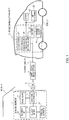
- FIG. 1 is a configuration diagram of a system for realizing an in-vehicle charging apparatus according to an embodiment of the present invention.
- in-house equipment 1 of house 10 and in-vehicle charging apparatus 21 of vehicle 2 are connected to each other using charging cable (power line) 4 via earth leakage circuit-breaker (EVSE) 3.
- EVSE earth leakage circuit-breaker
- One end of charging cable 4, for example, is connected to in-house equipment 1 using plug/outlet 5 having three polarities configured by single-phase AC of AC 100 V and an earth line.
- charging cable 4 is connected to a vehicle-side connection terminal having three polarities through a connection terminal, which includes a CPLT line terminal, having four polarities so as to be connected to in-vehicle charging apparatus 21 of vehicle 2.
- In-house equipment 1 includes panel board 11, house-side PLC terminal 12, internet modem 13, television set 14, and personal computer (PC) 15.
- Panel board 11 takes power from an outdoor power pole and branches power lines inside the house 10.
- House-side PLC terminal 12 is connected to the power line branched from panel board 11 and controls the supply of charging power to vehicle 2 side or establishes PLC between vehicle 2 side and the in-house equipment side.
- Internet modem 13 is connected to house-side PLC terminal 12 and transmits/receives information signals (vehicle information) according to the PLC.
- Television set 14 and PC 15 are connected to internet modem 13.
- Vehicle 2 includes: in-vehicle charging apparatus 21 that receives charging power transmitted from house-side PLC terminal 12 through charging cable 4 and controls charging of vehicle 2; camera 22; and air conditioner 23, for example.
- in-vehicle charging apparatus 21 includes storage battery 24, charger 25, vehicle-side PLC communication control section 26, storage section 27, and the like, and such elements will be described later in detail.
- a general driving apparatus for running vehicle 2 and/or the like do not directly relate to the present invention, so that the illustration thereof is omitted.
- the above-described vehicle-side connection terminal having four polarities used for connecting charging cable 4 to in-vehicle charging apparatus 21 is disposed at a predetermined position of a body of vehicle 2, the illustration of the vehicle-side connection terminal is omitted.
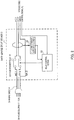
- FIG. 2 is a detailed circuit configuration diagram of earth leakage circuit-breaker 3 illustrated in FIG. 1 .
- earth leakage circuit-breaker 3 receives two single-phase AC lines (AC1 and AC2) and one ground line (GND) of charging cable 4 on in-house equipment 1 side and inputs two single-phase AC lines (AC1 and AC2) and one ground line (GND) to vehicle 2 side through contacts of leakage breaker relay 31 of earth leakage circuit-breaker 3 interposed between two single-phase AC lines (AC1 and AC2).
- GND ground line
- Such a configuration is the same as that of a generally used earth leakage circuit-breaker, so that a detailed description thereof will be omitted.
- earth leakage circuit-breaker 3 further includes electric leakage detecting section 32 and relay control section 33.
- Electric leakage detecting section 32 detects a change in a magnetic field of a coil changing in accordance with the occurrence of an electric leakage on power lines AC1 and AC2.
- Relay control section 33 receives an electric leakage detecting signal detected by electric leakage detecting section 32 and a control signal Sg transmitted form vehicle 2 and controls On/Off of the contact of leakage breaker relay 31.
- relay control section 33 Upon detection of an electric leakage by electric leakage detecting section 32, relay control section 33 turns off the contact of leakage breaker relay 31 regardless whether the control signal Sg is present on vehicle 2 side. In addition, in a case where a control signal Sg transmitted from vehicle 2 side represents an instruction for turning on the contact of leakage breaker relay 31 while an electric leakage is detected by electric leakage detecting section 32, relay control section 33 performs control such that the contact of leakage breaker relay 31 is turned on at a moment and then is immediately turned off.
- FIG 3 is a block diagram illustrating a detailed configuration of in-vehicle charging apparatus 21 illustrated in FIG. 1 .
- in-vehicle charging apparatus 21 includes storage battery 24, charger 25, vehicle-side PLC communication control section 26, storage section 27, and storage battery relay 28.
- Storage battery 24 supplies power for driving an electric motor (not illustrated in the figure) of vehicle 2 illustrated in FIG. 1 .
- Charger 25 receives AC charging power transmitted from in-house equipment 1 illustrated in FIG. 1 through charging cable 4, converts the AC power into DC power, and charges storage battery 24.
- Vehicle-side PLC communication control section 26 establishes PLC upon transmission of an information signal (vehicle information) of vehicle 2 side to in-house equipment 1 through charging cable 4.
- Storage section 27 stores various kinds of vehicle information of vehicle 2 side.
- Storage battery relay 28 opens or closes the main circuit of storage battery 24.
- charger 25 includes charger power supply circuit 25a that receives power of single-phase AC (AC1 and AC2) from earth leakage circuit-breaker 3 side illustrated in FIG. 2 , converts the AC power into DC power, and charges storage battery 24 and charging control section 25b that detects the completion of preparation of storage battery 24 and charger power supply circuit 25a for charging and transmits a control signal Sg to relay control section 33 of earth leakage circuit-breaker 3.
- the single-phase AC lines (AC1 and AC2) and the ground line (GND) of charging cable 4 are inputted to in-vehicle charging apparatus 21.
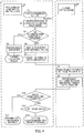
- FIG. 4 is a flowchart illustrating the flow of a PLC process mainly determined and performed by vehicle-side PLC communication control section 26 of in-vehicle charging apparatus 21 according to Embodiment 1 of the present invention.
- this flowchart illustrates a flow of the process that is performed between vehicle-side PLC communication control section 26 of in-vehicle charging apparatus 21 illustrated in FIG 3 and charging control section 25b of charger 25 and a process in which the vehicle information (data) of vehicle 2 is transmitted to in-house equipment 1 based on a determination mainly made by vehicle-side PLC communication control section 26.
- Step S1 when a PLC transmission sequence for transmitting vehicle information of vehicle 2 to in-house equipment 1 side using charging cable 4 is started (Step S1), vehicle-side PLC communication control section 26 detects the volume of the vehicle information stored in storage section 27 in a transmission memory buffer (Step S2). Then, vehicle-side PLC communication control section 26 determines whether or not a PLC communication connection (communication line) between vehicle 2 and in-house equipment 1 (house-side PLC terminal 12) has been established using charging cable 4 (Step S3).
- PLC communication connection communication line
- vehicle-side PLC communication control section 26 for example, exchanges a regular PLC packet between vehicle 2 and in-house equipment 1 or detects a voltage of the AC line of charging cable 4. In this way, vehicle-side PLC communication control section 26 starts normal transmission for transmitting vehicle information (data) of vehicle 2 to in-house equipment 1 while continuously detecting whether or not the communication connection between vehicle 2 and in-house equipment 1 is normal (Step S4). Then, vehicle-side PLC communication control section 26 performs a normal transmission process for a regular packet according to PLC while continuing to charge storage battery 24 (Step S5).
- vehicle-side PLC communication control section 26 performs a transmission-start determining process (Step S6).
- the transmission-start determining process is a process of determining a condition (form) in which the vehicle information of vehicle 2 is transmitted to in-house equipment 1 so as to establish a PLC communication connection by turning on leakage breaker relay 31 of earth leakage circuit-breaker 3 only when the vehicle information is transmitted.
- the transmission-start determining process for the vehicle information is a process in which a transmission start time point is determined based on the condition (form) of the vehicle information.
- this process there are a process in which vehicle information is transmitted when the capacity of the transmission memory buffer of the vehicle information stored in storage section 27 of in-vehicle charging apparatus 21 is full, a process in which vehicle information having a high priority level is transmitted, and a process in which vehicle information having a large evaluation value determined by priority level ⁇ data size is transmitted.
- the transmission-start determining process will be described later in detail.
- Step S6 vehicle-side PLC communication control section 26 requests charging control section 25b of charger 25 to turn on leakage breaker relay 31 of earth leakage circuit-breaker 3 illustrated in FIG. 2 (Step S7). Then, charging control section 25b receives the request for turning on leakage breaker relay 31 (Step S8) and performs the request for turning on leakage breaker relay 31 by transmitting turning-on information of leakage breaker relay 31 to earth leakage circuit-breaker 3 as a control signal Sg through a control signal line (Step S9)
- vehicle-side PLC communication control section 26 determines whether a PLC communication connection has been established (Step S10). Then, in a case where a PLC communication connection has not been established (No in Step S10), vehicle-side PLC communication control section 26 determines that there is an abnormality in a certain portion of charging cable 4 and determines that transmission is impossible (Step S11).
- Step S10 vehicle-side PLC communication control section 26 starts the process of transmitting the vehicle information (data) of vehicle 2 to in-house equipment 1 (Step S12), and the process proceeds to a sequence (Step B) of turning off leakage breaker relay 31 to be described later when the transmission of predetermined vehicle information (data) is completed (Step S13).
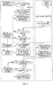
- FIG. 5 is a flowchart illustrating the flow of a PLC process mainly determined and performed by charging control section 25b of charger 25 according to Embodiment 2 of the present invention.
- this flowchart illustrates a flow of the process that is performed between vehicle-side PLC communication control section 26 of in-vehicle charging apparatus 21 illustrated in FIG. 3 and charging control section 25b of charger 25 and a process in which the vehicle information (data) of vehicle 2 is transmitted to in-house equipment 1 based on a determination mainly made by charging control section 25b of charger 25.
- Step S1 when a PLC transmission sequence for transmitting vehicle information of vehicle 2 to in-house equipment 1 side using charging cable 4 is started (Step S1), vehicle-side PLC communication control section 26 detects the volume of the vehicle information stored in storage section 27 in a transmission memory buffer (Step S2).
- vehicle-side PLC communication control section 26 requests charging control section 25b to check whether or not charger 25 of in-vehicle charging apparatus 21 is in the middle of a charging process (Step S21). Then, charging control section 25b of charger 25 replies to vehicle-side PLC communication control section 26 with a charging status (Step S22).
- vehicle-side PLC communication control section 26 determines whether or not a leakage occurs during the charging process based on detection information acquired by electric leakage detecting section 32 of earth leakage circuit-breaker 3 (Step S23).
- vehicle-side PLC communication control section 26 determines that the transmission of vehicle information (data) cannot be performed (Step S24) and ends the transmission process.
- the vehicle information (data) transmission process is immediately completed without turning on leakage breaker relay 31.
- vehicle-side PLC communication control section 26 determines whether or not a charging process using charging cable 4 is in the middle of the process (Step S25).
- a charging process using charging cable 4 is in the middle of the process (Yes in Step S25)
- a PLC communication connection between vehicle 2 and in-house equipment 1 has already been established. Accordingly, vehicle-side PLC communication control section 26 starts normal transmission for transmitting vehicle information (data) of vehicle 2 to in-house equipment 1 (Step S4) and performs the normal transmission process through PLC (Step S5).
- vehicle-side PLC communication control section 26 performs a transmission-start determining process (Step S6).
- the transmission-start determining process is a process of determining a condition (form) on which the vehicle information of vehicle 2 is transmitted to in-house equipment 1 so as to establish a PLC communication connection by turning on leakage breaker relay 31 of earth leakage circuit-breaker 3 only when the vehicle information is transmitted.
- the transmission-start determining is a process to determine a transmission start time point based on the condition (form) of the vehicle information (data).
- Examples of this process include: a process in which vehicle information is transmitted when the capacity of the transmission buffer of the vehicle information stored in storage section 27 of in-vehicle charging apparatus 21 is full; a process in which vehicle information having a high priority level is transmitted; and a process in which vehicle information having a large evaluation value determined by priority level ⁇ data size is transmitted.
- the transmission-start determining process will be described later in detail.
- vehicle-side PLC communication control section 26 requests charging control section 25b of charger 25 to perform PLC communication control using charger 25 by turning on leakage breaker relay 31 of earth leakage circuit-breaker 3 illustrated in FIG 2 (Step S7). Then, charging control section 25b receives the request for turning on leakage breaker relay 31 (Step S8) and performs the request for turning on leakage breaker relay 31 by transmitting turning-on information of leakage breaker relay 31 to earth leakage circuit-breaker 3 as a control signal Sg through the control signal line (Step S9)
- vehicle-side PLC communication control section 26 determines whether a PLC communication connection has been established (Step S10). Then, in a case where a PLC communication connection has not been established (No in Step S10), vehicle-side PLC communication control section 26 determines that there is an abnormality in a certain portion of charging cable 4 and determines that transmission is impossible (Step S11).
- Step S10 vehicle-side PLC communication control section 26 starts transmitting the vehicle information (data) of vehicle 2 to in-house equipment 1 (Step S12), and the process proceeds to a sequence of turning off leakage breaker relay 31 (Step B) to be described later, upon completion of the transmission of the vehicle information (data) (Step S13).
- determination criteria for starting the transmission of the vehicle information include following three determination reference patterns (1) to (3).
- FIG. 6 is a flowchart illustrating the flow of Pattern 1 of the transmission-start determining process in Step S6 illustrated in FIG 4 or 5 according to Embodiment 3 of the present invention.
- the transmission-start determining process of Pattern 1 is a determination process for starting transmission using PLC when the capacity of the transmission memory buffer of the vehicle information stored in storage section 27 is full.
- vehicle-side PLC communication control section 26 of in-vehicle charging apparatus 21 calculates the volume of the vehicle information, which has been stored in storage section 27, in the transmission memory buffer (Step S32). Then, vehicle-side PLC communication control section 26 determines whether or not the data size of the vehicle information, which has been stored, in the transmission memory buffer is a predetermined value or greater (Step S33).
- vehicle-side PLC communication control section 26 ends the transmission determining process for the vehicle information (Step S34), establishes PLC at a time point when the data size of the vehicle information stored in the transmission memory buffer is just the predetermined value or greater, and transmits data altogether.
- Step S33 when the data size in the transmission memory buffer of the vehicle information that is stored in storage section 27 is not the predetermined value or greater in Step S33 (No in Step S33), the process is returned to Step S2 illustrated in FIGS. 4 and 5 (Step S35), and the detection of the volume of the vehicle information, which is stored in storage section 27, in the transmission memory buffer is continued.
- the flow of the transmission determining process for the vehicle information illustrated in Steps S31 to S34 described above represents the following.
- no charging in other words, when leakage breaker relay 31 of earth leakage circuit-breaker 3 is blocked, and PLC is not established, leakage breaker relay 31 of earth leakage circuit-breaker 3 is turned on when the volume of the vehicle information is a predetermined amount or greater, a communication connection according to PLC is temporarily established, and data is transmitted to house-side PLC terminal 12 of in-house equipment 1 altogether.
- leakage breaker relay 31 of earth leakage circuit-breaker 3 is turned off so as to cause the vehicle-side connection terminal of charging cable 4 to be in the non-voltage state, whereby electrical safety is ensured.
- the vehicle information transmitted from in-vehicle charging apparatus 21 at the moment can be monitored using the screen of television set 14 or PC 15 of in-house equipment 1.
- FIG 7 is a flowchart illustrating the flow of Pattern 2 of the transmission-start determining process in Step S6 illustrated in FIG 4 or 5 according to Embodiment 3 of the present invention.
- the transmission-start determining process of Pattern 2 is a determination process for assigning priority levels to vehicle information in advance and transmitting vehicle information having a high priority level using PLC.
- Step S41 vehicle-side PLC communication control section 26 of in-vehicle charging apparatus 21 calculates the volume of the vehicle information, which has been stored in storage section 27, in the transmission memory buffer (Step S42). Then, vehicle-side PLC communication control section 26 determines whether or not the data size of the vehicle information, which has been stored, in the transmission memory buffer is a predetermined value or greater (Step S43).
- Step S43 the transmission determining process ends (Step S46).
- the priority level of newly stored data at the time of storing new vehicle information in storage section 27 is checked (Step S44).
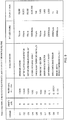
- Step S44 the priority level of newly stored data of vehicle information is checked based on Table A in which a priority level, a priority level coefficient, a data size example, and an evaluation value for each category of the vehicle information are compared with each other.
- Table A illustrated in FIG 9 represents a table of a case where a command and vehicle information have one-to-one correspondence.
- Step S44 the priority level of newly stored data of vehicle information is checked based on Table A illustrated in FIG. 9 , and whether or not there is vehicle information having a priority level of a specified value or greater (for example, a priority level of "4" or greater) is determined (Step S45).
- vehicle information having a priority level of a specified value or greater for example, a priority level of "4" or greater
- the transmission determining process ends (Step S46), PLC is established, and the vehicle information stored in the transmission memory buffer is transmitted altogether.
- PLC may be established, and only vehicle information having a priority level of a specified value or greater (for example, a priority level of "4" or greater) may be transmitted.
- a priority level of a specified value or greater for example, a priority level of "4" or greater
- Step S45 when there is no vehicle information having a priority level of the specified value or greater (for example, a priority level of "4" or greater) in Step S45 (No in Step S45), the process is returned to Step S2 illustrated in FIGS. 4 and 5 (Step S47), and the detection of the volume of the vehicle information, which is stored in storage section 27, in the transmission memory buffer is continued.
- a priority level of the specified value or greater for example, a priority level of "4" or greater
- the flow of the transmission determining process for vehicle information illustrated in Steps S41 to S46 described above represents the following.
- no charging that is, when PLC is not established due to blocking of leakage breaker relay 31 of earth leakage circuit-breaker 3
- leakage breaker relay 31 of earth leakage circuit-breaker 3 is turned on only when there is vehicle information having a priority level of a specified value or greater, a communication connection through PLC is temporarily established, and only data of the vehicle information having a priority level of the specified value or greater is transmitted to house-side PLC terminal 12 of in-house equipment 1 altogether.
- leakage breaker relay 31 of earth leakage circuit-breaker 3 is turned off so as to cause the vehicle-side connection terminal of charging cable 4 to be in a non-voltage state, whereby electrical safety is ensured.
- the vehicle information having high priority levels, which has been transmitted at that time can be monitored using the screen of television set 14 or PC 15 of in-house equipment 1.
- FIG. 8 is a flowchart illustrating the flow of Pattern 3 of the transmission-start determining process in Step S6 illustrated in FIG. 4 or 5 according to Embodiment 3 of the present invention.
- the transmission-start determining process of Pattern 3 is a determination process for assigning a priority level coefficient to vehicle information in advance and transmitting vehicle information having an evaluation value, which is determined based on "priority level coefficient ⁇ data size," of a specified value or greater through PLC.
- Step S51 vehicle-side PLC communication control section 26 of in-vehicle charging apparatus 21 calculates the volume of the vehicle information, which has been stored in storage section 27, in the transmission memory buffer (Step S52). Then, vehicle-side PLC communication control section 26 determines whether or not the data size of the vehicle information, which has been stored in storage section 27, in the transmission memory buffer is a predetermined value or greater (Step S53). Here, when the data size of data stored in the transmission memory buffer is the predetermined value or greater (Yes in Step S53), the transmission determining process ends (Step S56).
- FIG. 9 is a diagram illustrating Table A in which a priority level, a priority coefficient, a data size example, and an evaluation value for vehicle information are compared with each other.
- an evaluation value is calculated for each type (category) of vehicle information by multiplying a priority level coefficient and a data size together that are determined for each type (category) of the vehicle information.
- the evaluation value is calculated as 4,000,000.
- Step S55 whether or not the evaluation value of the vehicle information calculated in Step S54 as above is a specified value or greater is determined (Step S55).
- the transmission determining process ends (Step S56), PLC is established, and only the vehicle information having an evaluation value of the specified value or greater is transmitted.
- the transmission determining process ends, and the vehicle information stored in storage section 27 is transmitted altogether using PLC.
- only the vehicle information of which the evaluation value is a specified value or greater may be configured to be transmitted.
- Step S55 when there is no vehicle information of which the evaluation value is the specified value or greater in Step S55 (No in Step S55), the process is returned to Step S2 illustrated in FIGS. 4 and 5 (Step S57), and the detection of the volume of the vehicle information, which is stored in storage section 27, in the transmission memory buffer is continued.
- the flow of the transmission determining process for vehicle information illustrated in Steps S51 to S56 described above represents the following.
- no charging in other words, when leakage breaker relay 31 of earth leakage circuit-breaker 3 is blocked and PLC is not established, leakage breaker relay 31 of earth leakage circuit-breaker 3 is turned on only when vehicle information of which the evaluation value is a specified value or greater is present, a communication connection through PLC is temporarily established, and only data of the vehicle information of which the evaluation value is the specified value or greater is transmitted to house-side PLC terminal 12 of in-house equipment 1 altogether.
- leakage breaker relay 31 of earth leakage circuit-breaker 3 is turned off so as to cause the vehicle-side connection terminal of charging cable 4 to be in the non-voltage state, whereby electrical safety is ensured.
- the vehicle information having a high evaluation value transmitted at that time can be monitored using the screen of television set 14 or PC 15 of in-house equipment 1. For example, when a suspicious person comes close to a vehicle parked in a garage at night, a sensor camera image (urgent) is immediately projected onto the screen of television set 14 or PC 15. Thus, the image can be used for preventing vehicle theft or the like.
- the transmission determination criterion for vehicle information at a time when charging is stopped is determined as below.
- the advantage of using the evaluation value of vehicle information as a transmission determination criterion is as follows.
- “sensor vibration detection information” of the vehicle information represented in Table A illustrated in FIG. 9 has a priority level of "3" and a data size of 16 bytes. Accordingly, in a case where the condition of the transmission determination criterion is a priority level of "5" or a volume of the vehicle information of 256 Kbytes in the memory buffer, the transmission criterion is not satisfied unless data (16 bytes) of "sensor vibration detection information” is detected 16,000 times or more. Accordingly, the transmission criterion of the vehicle information is not reached unless a considerable number of vibrations are detected. Therefore, for example, even when a vehicle is parked on an unpaved rough road for charging, and a vibration is detected from a large-size car passing by the side thereof or the like, there is no concern that the "sensor vibration detection information" is frequently transmitted.
- the threshold of the evaluation value of the vehicle information is set to 1,500.
- the evaluation value of the "sensor vibration detection information" of the vehicle information is 1,600, and accordingly, the "sensor vibration detection information" of a first time satisfies the condition of the transmission determination criterion. Accordingly, since the evaluation value of the vehicle information is the predetermined value or greater, PLC is established, and the vehicle information of the "sensor vibration detection information" can be transmitted, immediately.
- "indoor temperature abnormality information" of the vehicle information represented in Table A illustrated in FIG. 9 is a phenomenon which may occur on a daily basis, and accordingly, the priority level coefficient is set to be low (a priority level coefficient of 10), and the evaluation value of the vehicle information is suppressed to be low as 160.
- the priority level coefficient is set to be low (a priority level coefficient of 10), and the evaluation value of the vehicle information is suppressed to be low as 160.
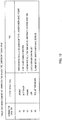
- FIG. 10 is a diagram illustrating Table B in which a command for each type and a content of each type of vehicle information are compared with each other.
- the content of each type of the vehicle information there are urgent information, maintenance information, warning information, user information, and regular transmission information.
- the urgent information is information acquired by grouping related information such as vibration detection information of the vehicle, electric leakage detection information, and sensor camera image (urgent) information.
- a transmission determination may be performed based on the content of each type of the grouped vehicle information as Pattern 4 of the transmission determination criterion of vehicle information, as represented in Table B illustrated in FIG. 10 , other than the transmission determination criterion of vehicle information from the three patterns described above.
- the criterion of the transmission determination in this case is as follows.
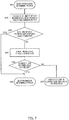
- FIG 11 is a flowchart illustrating the flow of the process of ending PLC by switching leakage breaker relay 31 to an Off sequence using vehicle-side PLC communication control section 26 in Embodiment 4 of the present invention.
- Step S61 when the turning-off sequence of leakage breaker relay 31 is started (Step S61), a packet is transmitted from the memory buffer including already stored data in storage section 27 (Step S62), and it is determined whether the transmission of the packet is successful (Step S63).
- Step S63 data that has been transmitted is removed from the memory buffer in which the data has been stored, so as to increase a free space of storage section 27 (Step S64).
- vehicle-side PLC communication control section 26 determines whether or not the memory buffer including already stored data in storage section 27 has been emptied (Step S65).
- vehicle-side PLC communication control section 26 determines whether or not data is currently received (Step S66).
- vehicle-side PLC communication control section 26 repeats the process of Step S65 for determining whether or not the memory buffer including already stored data has been emptied and the process of Step S66 for determining whether or not data is currently received and waits for the completion of the reception of data (Step S67).
- Step S66 vehicle-side PLC communication control section 26 completes the transmission process for data (Step S68) and requests charging control section 25b to transmit a control signal Sg for turning off leakage breaker relay 31 (Step S69).
- charging control section 25b receives the turning-off request signal for leakage breaker relay 31 (Step S70) and requests relay control section 33 of earth leakage circuit-breaker 3 to turn off leakage breaker relay 31 (Step S71). Accordingly, leakage breaker relay 31 is turned off, and the PLC communication connection is cut off (Step S72), and the turning-off sequence of leakage breaker relay 31 ends (Step S73).
- Step S74 determines whether or not a PLC communication connection has been established. In a case where the PLC communication connection has been established (Yes in Step S74), a process of retransmitting the packet is performed (Step S75), and the process of determining whether or not the transmission of a packet is successful in Step S63 described above is repeated. On the other hand, in a case where a PLC communication connection has not been established in Step S74 (No in Step S74), all the data of the memory buffer of storage section 27 is deleted (Step S76) so as to empty the memory buffer for storing new updated information, and the process proceeds to a transmission completing step of Step S68.
- FIG 12 is a flowchart illustrating the flow of a PLC connection at the time of starting charging, which is generally performed.
- Step S81 when a charging starting sequence is started (Step S81), first, charging cable 4 is connected to in-house equipment 1 on the input side of earth leakage circuit-breaker 3 (Step S82). Then, relay control section 33 of earth leakage circuit-breaker 3 checks whether a constant voltage is supplied from in-house equipment 1 to earth leakage circuit-breaker 3 and whether the control signal line is in a conductive state (Step S83).
- charging control section 25b of in-vehicle charging apparatus 21 detects that charging cable 4 is connected to in-vehicle charging apparatus 21 side (Step S84) and determines whether or not the preparation for charging has been completed (Step S85).
- the process waits for the completion of the preparation for charging, and, when the preparation for charging is completed (Yes in Step S85), charging control section 25b of in-vehicle charging apparatus 21 transmits a control signal Sg to relay control section 33 of earth leakage circuit-breaker 3 through the control signal line (Step S86).
- relay control section 33 of earth leakage circuit-breaker 3 detects the control signal Sg and turns on leakage breaker relay 31 (Step S87). Then, charging power (AC power) is supplied from in-house equipment 1 to in-vehicle charging apparatus 21, and storage battery relay 28 is turned on by charging control section 25b, whereby charging of storage battery 24 is started (Step S88). Then, vehicle-side PLC communication control section 26 sets up a communication connection according to PLC between in-vehicle charging apparatus 21 and house-side PLC terminal 12 (Step S89) and ends the charging starting sequence (Step S90). Accordingly, communication according to PLC can be also performed during the charging process.
- in-vehicle charging apparatus 21 of an embodiment of the present invention when earth leakage circuit-breaker 3 is open, and charging using charging cable 4 is not performed, a communication connection according to PLC is established only for a minimum required time in accordance with any one of the following three patterns, and only necessary vehicle information is transmitted to in-house equipment 1. In addition, immediately after the transmission of the vehicle information is completed, the PLC communication connection is blocked, whereby electrical safety of the vehicle-side connection terminal is ensured.
- leakage breaker relay 31 of earth leakage circuit-breaker 3 is turned off so as to block the PLC communication connection (communication line). Accordingly, when charging is not performed, leakage breaker relay 31 of earth leakage circuit-breaker 3 is turned on only for a requisite minimum time so as to establish a PLC communication line, and stored data can be transmitted altogether. In addition, since the non-voltage state of the vehicle-side connection terminal of charging cable 4 can be maintained as long as possible, the electrical safety can be maintained at a relatively high level.
- vehicle-side PLC communication control section 26 constantly inquires charging control section 25b whether it is in the middle of a charging process. In a case where it is in the middle of the charging process, communication according to ordinary PLC is started, and the vehicle information is transmitted. On the other hand, in a case where it is not in the middle of the charging process, a process of transmitting the vehicle information altogether is performed at any one of timing when the data size of the vehicle information is a predetermined data size or greater, timing when vehicle information having a high priority level is present, and timing when there is vehicle information of which the evaluation value is high. In addition, when detecting whether or not charging is currently performed, vehicle-side PLC communication control section 26 does not need to determine again whether a communication line according to PLC is established.
- the capacity of storage section 27 can be maximally used in an effective manner.
- vehicle information having a priority level lower than a predetermined priority level is deleted. Accordingly, even when the transmission of the vehicle information is not completed, in a case where a communication line according to PLC cannot be established, an empty area of storage section 27 can be effectively secured by deleting vehicle information having a low priority level.
- vehicle-side PLC communication control section 26 does not issue an instruction for turning on leakage breaker relay 31 to charging control section 25b.
- leakage breaker relay 31 is turned off due to the occurrence of an electric leakage in charging cable (power line) 4
- a malfunction for turning on leakage breaker relay 31 at least one moment by transmitting a control signal Sg used for turning on leakage breaker relay 31 can be prevented.
- the present invention is not limited to each embodiment described above, but various changes can be made therein within a range not departing from the concept thereof.
- the conditions for setting up a communication line according to PLC during the stop of charging are not limited to the conditions of three patterns described above, but may be changed to conditions desired by a user.
- the present invention is not limited thereto, and it is apparent that the present invention can be applied to an in-vehicle charging apparatus used for charging a storage battery installed in an ordinary gasoline-powered vehicle.
- the present invention can be not only used as an in-vehicle charging apparatus of an HEV or an EV but also can be used effectively as an in-vehicle charging apparatus of a general vehicle such as a gasoline-powered vehicle.
Landscapes
- Engineering & Computer Science (AREA)
- Power Engineering (AREA)
- Transportation (AREA)
- Mechanical Engineering (AREA)
- Life Sciences & Earth Sciences (AREA)
- Sustainable Development (AREA)
- Sustainable Energy (AREA)
- Manufacturing & Machinery (AREA)
- Chemical & Material Sciences (AREA)
- Chemical Kinetics & Catalysis (AREA)
- Electrochemistry (AREA)
- General Chemical & Material Sciences (AREA)
- Charge And Discharge Circuits For Batteries Or The Like (AREA)
- Electric Propulsion And Braking For Vehicles (AREA)
- Secondary Cells (AREA)
- Remote Monitoring And Control Of Power-Distribution Networks (AREA)
Claims (13)
- Fahrzeuginterne Ladevorrichtung (21) zum Laden einer Speicherbatterie (24), die in einem Fahrzeug installiert ist, und zwar von einer Energie- bzw. Stromversorgung, die außerhalb des Fahrzeugs zur Verfügung gestellt wird, durch eine Energie- bzw. Stromleitung, die sich via bzw. über einen Fehlerstrom-Schutzschalter (3) erstreckt, wobei die Vorrichtung (21) aufweist:einen Speicherabschnitt (27), der eingerichtet ist, um Fahrzeuginformationen zu speichern, die sich auf das Fahrzeug beziehen;einen fahrzeugseitigen Stromleitungskommunikations-PLC-Kommunikationssteuerungsabschnitt (26), der eingerichtet ist, um ein Steuersignal zum Schließen des Fehlerstrom-Schutzschalters (3) auszugeben, und um anschließend eine PLC-Kommunikationsleitung zu etablieren bzw. einzurichten, die die Energie- bzw. Stromleitung als eine Kommunikationsleitung verwendet und die Fahrzeuginformationen, die in dem Speicherabschnitt (27) gespeichert sind, nach außerhalb von dem Fahrzeug überträgt, wenn es bestimmt wird, dass die Fahrzeuginformationen, die in dem Speicherabschnitt (27) gespeichert sind, erfordern, nach außerhalb von dem Fahrzeug übertragen zu werden,wobei der fahrzeugseitige PLC-Kommunikationssteuerungsabschnitt (26) eingerichtet ist, um Steuerung durchzuführen, so dass der Fehlerstrom-Schutzschalter (3) ausgeschaltet wird, und zwar bei Fertigstellung bzw. Komplettierung der Übertragung der Fahrzeuginformationen.
- Fahrzeuginterne Ladevorrichtung (21) gemäß Anspruch 1, wobei der fahrzeugseitige PLC-Kommunikationssteuerungsabschnitt (26) eingerichtet ist, um ein Steuersignal zum Schließen des Fehlerstrom-Schutzschalters (3) auszugeben, wenn die Speicherbatterie (24), die in dem Fahrzeug installiert ist, nicht von der Energie- bzw. Stromversorgung geladen wird, die außerhalb von dem Fahrzeug zur Verfügung gestellt wird.
- Fahrzeuginterne Ladevorrichtung (21) gemäß Anspruch 1, wobei, wenn die Fahrzeuginformationen von einer vorbestimmten Datengröße bzw. -umfang oder größer in dem Speicherabschnitt (27) gespeichert werden, ist der fahrzeugseitige PLC-Kommunikationssteuerungsabschnitt (26) eingerichtet, um zu bestimmen, dass die Fahrzeuginformationen erfordern, nach außerhalb von dem Fahrzeug übertragen zu werden, und der fahrzeugseitige PLC-Kommunikationssteuerungsabschnitt (26) ist eingerichtet, um dann eine PLC-Kommunikationsleitung zu etablieren bzw. einzurichten, und um dann nach außerhalb von dem Fahrzeug all die Fahrzeuginformationen zu übertragen, welche in dem Speicherabschnitt (27) gespeichert sind und welche übertragbar sind.
- Fahrzeuginterne Ladevorrichtung (21) gemäß Anspruch 1, wobei:eine Prioritätsebene bzw. ein Prioritätsniveau für jede Kategorie eingestellt bzw. festgelegt ist, und zwar für die Fahrzeuginformationen, die in dem Speicherabschnitt (27) gespeichert sind; undwobei der fahrzeugseitige PLC-Kommunikationssteuerungsabschnitt (26) eingerichtet ist, um zu bestimmen, dass die Fahrzeuginformationen erfordern, nach außerhalb von dem Fahrzeug übertragen zu werden, wenn die Fahrzeuginformationen, die eine Prioritätsebene bzw. ein Prioritätsniveau haben, die bzw. das höher als eine vorbestimmte Ebene bzw. Niveau ist, in dem Speicherabschnitt (27) gespeichert sind, und wobei der fahrzeugseitige PLC-Kommunikationssteuerungsabschnitt (26) eingerichtet ist, um dann eine PLC-Kommunikationsleitung zu etablieren bzw. einzurichten und um dann nach außerhalb von dem Fahrzeug all die Fahrzeuginformationen zu übertragen, welche in dem Speicherabschnitt (27) gespeichert sind und welche übertragbar sind.
- Fahrzeuginterne Ladevorrichtung (21) gemäß Anspruch 1, wobei:eine Prioritätsebene bzw. ein Prioritätsniveau für jede Kategorie eingestellt bzw. festgelegt ist, und zwar für die Fahrzeuginformationen, die in dem Speicherabschnitt (27) gespeichert sind; undwobei der fahrzeugseitige PLC-Kommunikationssteuerungsabschnitt (26) eingerichtet ist, um zu bestimmen, dass die Fahrzeuginformationen erfordern, nach außerhalb von dem Fahrzeug übertragen zu werden, wenn die Fahrzeuginformationen, die eine Prioritätsebene bzw. ein Prioritätsniveau haben, die bzw. das höher als eine vorbestimmte Ebene bzw. Niveau ist, in dem Speicherabschnitt (27) gespeichert sind, und wobei der fahrzeugseitige PLC-Kommunikationssteuerungsabschnitt (26) eingerichtet ist, um dann eine PLC-Kommunikationsleitung zu etablieren bzw. einzurichten und um dann nach außerhalb von dem Fahrzeug die Fahrzeuginformationen zu übertragen, welche in dem Speicherabschnitt (27) gespeichert sind, und welche die Prioritätsebene bzw. das Prioritätsniveau haben, die bzw. das höher als eine vorbestimmte Ebene bzw. Niveau ist.
- Fahrzeuginterne Ladevorrichtung (21) gemäß Anspruch 1, wobei:ein Auswertungs- bzw. Evaluationswert, der durch Multiplizieren eines Prioritätsebenen- bzw. Prioritätsniveaukoeffizienten und einer Datengröße bzw. -umfang erlangt wird, für jede Kategorie von den Fahrzeuginformationen eingestellt bzw. festgelegt wird, die in dem Speicherabschnitt (27) gespeichert sind; undwobei der PLC-Kommunikationssteuerungsabschnitt (26) eingerichtet ist, um zu bestimmen, dass die Fahrzeuginformationen erfordern, nach außerhalb von dem Fahrzeug übertragen zu werden, wenn die Fahrzeuginformationen, die einen Auswertungs- bzw. Evaluationswert haben, der höher als ein vorbestimmter Wert ist, in dem Speicherabschnitt (27) gespeichert sind, und wobei der fahrzeugseitige PLC-Kommunikationssteuerungsabschnitt (26) eingerichtet ist, um dann eine PLC-Kommunikationsleitung zu etablieren bzw. einzurichten und um dann nach außerhalb von dem Fahrzeug all die Fahrzeuginformationen zu übertragen, welche in dem Speicherabschnitt (27) gespeichert sind und welche übertragbar sind.
- Fahrzeuginterne Ladevorrichtung (21) gemäß Anspruch 1, wobei:ein Auswertungs- bzw. Evaluationswert, der durch Multiplizieren eines Prioritätsebenen- bzw. Prioritätsniveaukoeffizienten und einer Datengröße bzw. -umfang erlangt wird, für jede Kategorie von den Fahrzeuginformationen eingestellt bzw. festgelegt wird, die in dem Speicherabschnitt (27) gespeichert sind; undwobei der fahrzeugseitige PLC-Kommunikationssteuerungsabschnitt (26) bestimmt, dass die Fahrzeuginformationen erfordern, nach außerhalb vom dem Fahrzeug übertragen zu werden, wenn die Fahrzeuginformationen, die einen Auswertungs- bzw. Evaluationswert haben, der höher als ein vorbestimmter Wert ist, in dem Speicherabschnitt (27) gespeichert sind, und wobei der fahrzeugseitige PLC-Kommunikationssteuerungsabschnitt (26) eingerichtet ist, um eine PLC-Kommunikationsleitung zu etablieren bzw. einzurichten, und um dann nach außerhalb vom dem Fahrzeug die Fahrzeuginformationen zu übertragen, welche in dem Speicherabschnitt (27) gespeichert sind, und welche den Auswertungs- bzw. Evaluationswert haben, der höher als ein vorbestimmter Wert ist.
- Fahrzeuginterne Ladevorrichtung (21) gemäß Anspruch 1, wobei der fahrzeugseitige PLC-Kommunikationssteuerungsabschnitt (26) eingerichtet ist, um zu bestimmen, ob die Fahrzeuginformationen, die in dem Speicherabschnitt (27) gespeichert sind, erfordern, nach außerhalb von dem Fahrzeug übertragen zu werden oder nicht, und zwar wenn der Empfang von Informationen erfolgt ist, die bedeuten, dass der Fehlerstrom-Schutzschalter (3) die Energie- bzw. Stromleitung blockiert bzw. sperrt.
- Fahrzeuginterne Ladevorrichtung (21) gemäß Anspruch 1, wobei die Fahrzeuginformationen wenigstens eine von Unterbrechungs- bzw. Störungsdetektierungsinformation, Batterieleckagedetektierungsinformation, ein Vorrangsensorkamerabild, Fahrzeuginnenraumtemperatur-Abnormalitätsinformation, Ladestromstärkereduzierungsinformation, Sensorvibrationsdetektierungsinformation, Instandhaltungs- bzw. Wartungsinformation, ein regelmäßiges bzw. reguläres Sensorkamerabild, und fortlaufende Chronikinformationen vom dem Fahrzeug sind, wobei die fortlaufenden Chronikinformationen regelmäßig bzw. regulär zu einem Server übertragen werden.
- Fahrzeuginterne Ladevorrichtung (21) gemäß Anspruch 9, wobei der fahrzeugseitige PLC-Kommunikationssteuerungsabschnitt (26) eingerichtet ist, um zu bestimmen, dass die Fahrzeuginformationen, die in dem Speicherabschnitt (27) gespeichert sind, erfordern, um außerhalb vom dem Fahrzeug übertragen zu werden, wenn die Unterbrechungs- bzw. Störungsdetektierungsinformation, die Batterieleckagedetektierungsinformation, das Vorrangsensorkamerabild, die Fahrzeuginnenraumtemperatur-Abnormalitätsinformation oder die Ladestromstärkereduzierungsinformation in dem Speicherabschnitt (27) gespeichert sind.
- Fahrzeuginterne Ladevorrichtung (21) gemäß Anspruch 1, wobei der fahrzeugseitige PLC-Kommunikationssteuerungsabschnitt (26) eingerichtet ist, um die Fahrzeuginformationen zu löschen, welche von dem Speicherabschnitt (27) übertragen worden sind, und zwar nach der Übertragung von den Fahrzeuginformationen.
- Fahrzeuginterne Ladevorrichtung (21) gemäß Anspruch 4 oder 7, wobei der fahrzeugseitige PLC-Kommunikationssteuerungsabschnitt (26) eingerichtet ist, um die Fahrzeuginformationen zu löschen, die eine Prioritätsebene bzw. ein Prioritätsniveau haben, die bzw. das niedriger als eine vorbestimmte Prioritätsebene bzw. Prioritätsniveau ist, und zwar von dem Speicherabschnitt (27), wenn die Übertragung von den Fahrzeuginformationen nicht fertiggestellt bzw. komplettiert werden kann und auch wenn eine PLC-Kommunikationsleitung nicht etabliert bzw. eingerichtet ist.
- Fahrzeuginterne Ladevorrichtung (21) gemäß Anspruch 1, wobei der fahrzeugseitige PLC-Kommunikationssteuerungsabschnitt (26) eingerichtet ist, um nicht das Steuersignal zum Schließen des Fehlerstrom-Schutzschalters (3) zu übertragen, wenn Informationen empfangen werden, die bedeuten, dass ein elektrisches Leck bzw. Leckstrom von dem Fehlerstrom-Schutzschalter (3) vorhanden ist.
Applications Claiming Priority (2)
| Application Number | Priority Date | Filing Date | Title |
|---|---|---|---|
| JP2011072050A JP5849208B2 (ja) | 2011-03-29 | 2011-03-29 | 車載充電装置 |
| PCT/JP2012/002109 WO2012132405A1 (ja) | 2011-03-29 | 2012-03-27 | 車載充電装置 |
Publications (3)
| Publication Number | Publication Date |
|---|---|
| EP2692570A1 EP2692570A1 (de) | 2014-02-05 |
| EP2692570A4 EP2692570A4 (de) | 2015-11-18 |
| EP2692570B1 true EP2692570B1 (de) | 2020-07-22 |
Family
ID=46930180
Family Applications (1)
| Application Number | Title | Priority Date | Filing Date |
|---|---|---|---|
| EP12762866.7A Active EP2692570B1 (de) | 2011-03-29 | 2012-03-27 | Fahrzeuginterne ladevorrichtung |
Country Status (4)
| Country | Link |
|---|---|
| US (1) | US9409488B2 (de) |
| EP (1) | EP2692570B1 (de) |
| JP (1) | JP5849208B2 (de) |
| WO (1) | WO2012132405A1 (de) |
Families Citing this family (12)
| Publication number | Priority date | Publication date | Assignee | Title |
|---|---|---|---|---|
| US8988042B2 (en) * | 2011-08-25 | 2015-03-24 | Toyota Jidosha Kabushiki Kaisha | Vehicle, charging system and control method for vehicle |
| JP6168447B2 (ja) * | 2013-03-28 | 2017-07-26 | パナソニックIpマネジメント株式会社 | 給電制御装置 |
| JP6111500B2 (ja) * | 2013-03-29 | 2017-04-12 | パナソニックIpマネジメント株式会社 | 電気接続用コネクタ |
| EP2986466B1 (de) * | 2013-04-15 | 2017-06-07 | Volvo Truck Corporation | Verfahren und anordnung zur fehlererkennung beim laden eines energiespeichersystems |
| JP6247460B2 (ja) * | 2013-06-14 | 2017-12-13 | 日立オートモティブシステムズ株式会社 | 電池制御装置 |
| JP5761265B2 (ja) * | 2013-07-30 | 2015-08-12 | 株式会社デンソー | 車両用充電制御装置 |
| JP2016018295A (ja) * | 2014-07-07 | 2016-02-01 | 日立オートモティブシステムズ株式会社 | 情報処理システム |
| JP2016139865A (ja) * | 2015-01-26 | 2016-08-04 | 株式会社デンソー | 車両の周辺画像送信装置及びセキュリティシステム |
| KR101838508B1 (ko) * | 2016-01-07 | 2018-03-14 | 현대자동차주식회사 | 전기차 충전 방법 및 장치 |
| KR101996603B1 (ko) * | 2018-12-19 | 2019-07-04 | 중앙제어 주식회사 | 전기차 충전 시 전기차 충전기의 온도를 센싱하는 장치 |
| JP6947322B1 (ja) * | 2021-03-08 | 2021-10-13 | 株式会社デンソー | 電池管理システム |
| CN113525149A (zh) * | 2021-08-12 | 2021-10-22 | 长春捷翼汽车零部件有限公司 | 一种电能供给控制方法、装置、电子设备及存储介质 |
Family Cites Families (20)
| Publication number | Priority date | Publication date | Assignee | Title |
|---|---|---|---|---|
| US5272431A (en) | 1991-11-27 | 1993-12-21 | Nee Patrick W | Automatic power connector for recharging electric vehicles |
| JP3179387B2 (ja) | 1997-09-30 | 2001-06-25 | 日本電気移動通信株式会社 | 車両管理用データ伝送システム |
| JP4962939B2 (ja) * | 2006-03-03 | 2012-06-27 | トヨタ自動車株式会社 | 車両および車両の情報機器 |
| JP2008285075A (ja) * | 2007-05-18 | 2008-11-27 | Toyota Motor Corp | 車両および車両の故障診断方法 |
| JP2009165301A (ja) * | 2008-01-09 | 2009-07-23 | Denso Corp | 車両への電力供給制御装置および電力供給制御装置用のプログラム |
| JP4407753B2 (ja) * | 2008-01-15 | 2010-02-03 | トヨタ自動車株式会社 | 電動車両の充電システム |
| JP5353082B2 (ja) * | 2008-06-17 | 2013-11-27 | 株式会社オートネットワーク技術研究所 | 車両用電源制御装置 |
| JP2010004674A (ja) | 2008-06-20 | 2010-01-07 | Fujitsu Ten Ltd | 電子制御装置 |
| JP5267050B2 (ja) * | 2008-10-30 | 2013-08-21 | 株式会社豊田自動織機 | バッテリ残量モニタシステム |
| JP5420883B2 (ja) * | 2008-11-17 | 2014-02-19 | トヨタ自動車株式会社 | 充電コネクタおよび充電ケーブルユニット |
| JP5344895B2 (ja) | 2008-12-10 | 2013-11-20 | 矢崎総業株式会社 | 充電監視装置 |
| JP2010166768A (ja) | 2009-01-19 | 2010-07-29 | Fujitsu Ten Ltd | 制御装置、制御システム、制御方法 |
| JP5365366B2 (ja) | 2009-06-24 | 2013-12-11 | 株式会社豊田自動織機 | 車両充電システム |
| JP2011015530A (ja) * | 2009-07-02 | 2011-01-20 | Panasonic Corp | 漏電検知給電制御装置 |
| JP2011035975A (ja) | 2009-07-30 | 2011-02-17 | Toyota Motor Corp | 車両および車両の制御方法 |
| JP2011151717A (ja) | 2010-01-25 | 2011-08-04 | Toyota Motor Corp | 車両の情報伝達装置およびそれを備える電動車両 |
| JP2011172363A (ja) * | 2010-02-17 | 2011-09-01 | Toyota Industries Corp | 充電制御装置及び車両充電システム |
| JP5417280B2 (ja) * | 2010-08-04 | 2014-02-12 | 株式会社日立製作所 | 蓄電池制御装置,充電スタンド及び蓄電池制御方法 |
| US8669740B2 (en) * | 2011-01-19 | 2014-03-11 | Honda Motor Co., Ltd. | Vehicle charging system |
| DE112012005621B4 (de) * | 2012-01-10 | 2019-05-29 | Mitsubishi Electric Corporation | Haussicherheitssystem und durch dasselbe verwendetes fahrzeugmontiertes System |
-
2011
- 2011-03-29 JP JP2011072050A patent/JP5849208B2/ja active Active
-
2012
- 2012-03-27 WO PCT/JP2012/002109 patent/WO2012132405A1/ja active Application Filing
- 2012-03-27 EP EP12762866.7A patent/EP2692570B1/de active Active
- 2012-03-27 US US14/007,735 patent/US9409488B2/en active Active
Non-Patent Citations (1)
| Title |
|---|
| None * |
Also Published As
| Publication number | Publication date |
|---|---|
| JP5849208B2 (ja) | 2016-01-27 |
| JP2012210007A (ja) | 2012-10-25 |
| WO2012132405A1 (ja) | 2012-10-04 |
| EP2692570A1 (de) | 2014-02-05 |
| US20140015494A1 (en) | 2014-01-16 |
| US9409488B2 (en) | 2016-08-09 |
| EP2692570A4 (de) | 2015-11-18 |
Similar Documents
| Publication | Publication Date | Title |
|---|---|---|
| EP2692570B1 (de) | Fahrzeuginterne ladevorrichtung | |
| US9114716B2 (en) | Method and apparatus for high-voltage DC charging of battery-electric and plug-in hybrid electric vehicles | |
| EP2783899B1 (de) | Ladesystem und ladereservierungsverfahren | |
| US9178381B2 (en) | Storage battery control device, charging station, and storage battery control method | |
| EP3092149B1 (de) | Hybridfahrzeug mit einer einrichtung zum abschalten einer abgereicherten hilfsbatterie, um ein schnelleres aufladen der hauptbatterie zu erlauben | |
| JP5561441B2 (ja) | 車両、車両用制御方法および受電設備 | |
| EP2660949B1 (de) | Aufladevorrichtung für ein fahrzeug | |
| US20130088198A1 (en) | Electric charging system and electric charging method | |
| US20100194529A1 (en) | Management system for charging plug-in vehicle | |
| EP2787597A1 (de) | Ladesystem und ladereservierungsverfahren | |
| US9931946B2 (en) | Method and arrangement for controlling charging of an energy storage system | |
| KR101821008B1 (ko) | 전기 자동차 충전 장치 | |
| CN103326447B (zh) | 电动车无线充电系统 | |
| EP2986466B1 (de) | Verfahren und anordnung zur fehlererkennung beim laden eines energiespeichersystems | |
| JP2012135111A (ja) | 車両用充電ケーブル管理システム | |
| CN110816317B (zh) | 车载控制系统及车辆 | |
| JP5835180B2 (ja) | 車両 | |
| CN112092655B (zh) | 充电站通信系统、方法和充电站 | |
| KR20160106311A (ko) | 전기 자동차 충전 시스템 | |
| JP2013090459A (ja) | 電気自動車用充電装置 | |
| KR102320041B1 (ko) | 스마트그리드용 전기자동차의 양방향 충방전 방법 및 장치 | |
| CN112319300A (zh) | 一种智能充电器及其智能充电管理方法 | |
| KR20160109529A (ko) | 차량 충전 장치 | |
| CN117774690A (zh) | 一种用于储能系统和新能源汽车的配电盒和配电系统 |
Legal Events
| Date | Code | Title | Description |
|---|---|---|---|
| PUAI | Public reference made under article 153(3) epc to a published international application that has entered the european phase |
Free format text: ORIGINAL CODE: 0009012 |
|
| 17P | Request for examination filed |
Effective date: 20130923 |
|
| AK | Designated contracting states |
Kind code of ref document: A1 Designated state(s): AL AT BE BG CH CY CZ DE DK EE ES FI FR GB GR HR HU IE IS IT LI LT LU LV MC MK MT NL NO PL PT RO RS SE SI SK SM TR |
|
| DAX | Request for extension of the european patent (deleted) | ||
| RAP1 | Party data changed (applicant data changed or rights of an application transferred) |
Owner name: PANASONIC INTELLECTUAL PROPERTY MANAGEMENT CO., LT |
|
| RAP1 | Party data changed (applicant data changed or rights of an application transferred) |
Owner name: PANASONIC INTELLECTUAL PROPERTY MANAGEMENT CO., LT |
|
| RA4 | Supplementary search report drawn up and despatched (corrected) |
Effective date: 20151020 |
|
| RIC1 | Information provided on ipc code assigned before grant |
Ipc: B60L 11/18 20060101AFI20151013BHEP Ipc: H02J 13/00 20060101ALI20151013BHEP Ipc: B60L 3/04 20060101ALI20151013BHEP Ipc: H02J 7/00 20060101ALI20151013BHEP Ipc: H01M 10/48 20060101ALI20151013BHEP Ipc: H01M 10/44 20060101ALI20151013BHEP Ipc: B60L 3/00 20060101ALI20151013BHEP |
|
| STAA | Information on the status of an ep patent application or granted ep patent |
Free format text: STATUS: EXAMINATION IS IN PROGRESS |
|
| 17Q | First examination report despatched |
Effective date: 20190702 |
|
| REG | Reference to a national code |
Ref country code: DE Ref legal event code: R079 Ref document number: 602012071370 Country of ref document: DE Free format text: PREVIOUS MAIN CLASS: B60L0011180000 Ipc: B60L0053660000 |
|
| RIC1 | Information provided on ipc code assigned before grant |
Ipc: B60L 53/66 20190101AFI20191218BHEP |
|
| GRAP | Despatch of communication of intention to grant a patent |
Free format text: ORIGINAL CODE: EPIDOSNIGR1 |
|
| STAA | Information on the status of an ep patent application or granted ep patent |
Free format text: STATUS: GRANT OF PATENT IS INTENDED |
|
| INTG | Intention to grant announced |
Effective date: 20200210 |
|
| GRAS | Grant fee paid |
Free format text: ORIGINAL CODE: EPIDOSNIGR3 |
|
| GRAA | (expected) grant |
Free format text: ORIGINAL CODE: 0009210 |
|
| STAA | Information on the status of an ep patent application or granted ep patent |
Free format text: STATUS: THE PATENT HAS BEEN GRANTED |
|
| AK | Designated contracting states |
Kind code of ref document: B1 Designated state(s): AL AT BE BG CH CY CZ DE DK EE ES FI FR GB GR HR HU IE IS IT LI LT LU LV MC MK MT NL NO PL PT RO RS SE SI SK SM TR |
|
| REG | Reference to a national code |
Ref country code: GB Ref legal event code: FG4D |
|
| REG | Reference to a national code |
Ref country code: CH Ref legal event code: EP |
|
| REG | Reference to a national code |
Ref country code: DE Ref legal event code: R096 Ref document number: 602012071370 Country of ref document: DE |
|
| REG | Reference to a national code |
Ref country code: AT Ref legal event code: REF Ref document number: 1293085 Country of ref document: AT Kind code of ref document: T Effective date: 20200815 |
|
| REG | Reference to a national code |
Ref country code: IE Ref legal event code: FG4D |
|
| REG | Reference to a national code |
Ref country code: LT Ref legal event code: MG4D |
|
| REG | Reference to a national code |
Ref country code: AT Ref legal event code: MK05 Ref document number: 1293085 Country of ref document: AT Kind code of ref document: T Effective date: 20200722 |
|
| PG25 | Lapsed in a contracting state [announced via postgrant information from national office to epo] |
Ref country code: BG Free format text: LAPSE BECAUSE OF FAILURE TO SUBMIT A TRANSLATION OF THE DESCRIPTION OR TO PAY THE FEE WITHIN THE PRESCRIBED TIME-LIMIT Effective date: 20201022 Ref country code: HR Free format text: LAPSE BECAUSE OF FAILURE TO SUBMIT A TRANSLATION OF THE DESCRIPTION OR TO PAY THE FEE WITHIN THE PRESCRIBED TIME-LIMIT Effective date: 20200722 Ref country code: PT Free format text: LAPSE BECAUSE OF FAILURE TO SUBMIT A TRANSLATION OF THE DESCRIPTION OR TO PAY THE FEE WITHIN THE PRESCRIBED TIME-LIMIT Effective date: 20201123 Ref country code: LT Free format text: LAPSE BECAUSE OF FAILURE TO SUBMIT A TRANSLATION OF THE DESCRIPTION OR TO PAY THE FEE WITHIN THE PRESCRIBED TIME-LIMIT Effective date: 20200722 Ref country code: ES Free format text: LAPSE BECAUSE OF FAILURE TO SUBMIT A TRANSLATION OF THE DESCRIPTION OR TO PAY THE FEE WITHIN THE PRESCRIBED TIME-LIMIT Effective date: 20200722 Ref country code: AT Free format text: LAPSE BECAUSE OF FAILURE TO SUBMIT A TRANSLATION OF THE DESCRIPTION OR TO PAY THE FEE WITHIN THE PRESCRIBED TIME-LIMIT Effective date: 20200722 Ref country code: SE Free format text: LAPSE BECAUSE OF FAILURE TO SUBMIT A TRANSLATION OF THE DESCRIPTION OR TO PAY THE FEE WITHIN THE PRESCRIBED TIME-LIMIT Effective date: 20200722 Ref country code: FI Free format text: LAPSE BECAUSE OF FAILURE TO SUBMIT A TRANSLATION OF THE DESCRIPTION OR TO PAY THE FEE WITHIN THE PRESCRIBED TIME-LIMIT Effective date: 20200722 Ref country code: NO Free format text: LAPSE BECAUSE OF FAILURE TO SUBMIT A TRANSLATION OF THE DESCRIPTION OR TO PAY THE FEE WITHIN THE PRESCRIBED TIME-LIMIT Effective date: 20201022 Ref country code: GR Free format text: LAPSE BECAUSE OF FAILURE TO SUBMIT A TRANSLATION OF THE DESCRIPTION OR TO PAY THE FEE WITHIN THE PRESCRIBED TIME-LIMIT Effective date: 20201023 |
|
| PG25 | Lapsed in a contracting state [announced via postgrant information from national office to epo] |
Ref country code: RS Free format text: LAPSE BECAUSE OF FAILURE TO SUBMIT A TRANSLATION OF THE DESCRIPTION OR TO PAY THE FEE WITHIN THE PRESCRIBED TIME-LIMIT Effective date: 20200722 Ref country code: LV Free format text: LAPSE BECAUSE OF FAILURE TO SUBMIT A TRANSLATION OF THE DESCRIPTION OR TO PAY THE FEE WITHIN THE PRESCRIBED TIME-LIMIT Effective date: 20200722 Ref country code: PL Free format text: LAPSE BECAUSE OF FAILURE TO SUBMIT A TRANSLATION OF THE DESCRIPTION OR TO PAY THE FEE WITHIN THE PRESCRIBED TIME-LIMIT Effective date: 20200722 Ref country code: IS Free format text: LAPSE BECAUSE OF FAILURE TO SUBMIT A TRANSLATION OF THE DESCRIPTION OR TO PAY THE FEE WITHIN THE PRESCRIBED TIME-LIMIT Effective date: 20201122 |
|
| PG25 | Lapsed in a contracting state [announced via postgrant information from national office to epo] |
Ref country code: NL Free format text: LAPSE BECAUSE OF FAILURE TO SUBMIT A TRANSLATION OF THE DESCRIPTION OR TO PAY THE FEE WITHIN THE PRESCRIBED TIME-LIMIT Effective date: 20200722 |
|
| REG | Reference to a national code |
Ref country code: DE Ref legal event code: R097 Ref document number: 602012071370 Country of ref document: DE |
|
| PG25 | Lapsed in a contracting state [announced via postgrant information from national office to epo] |
Ref country code: CZ Free format text: LAPSE BECAUSE OF FAILURE TO SUBMIT A TRANSLATION OF THE DESCRIPTION OR TO PAY THE FEE WITHIN THE PRESCRIBED TIME-LIMIT Effective date: 20200722 Ref country code: EE Free format text: LAPSE BECAUSE OF FAILURE TO SUBMIT A TRANSLATION OF THE DESCRIPTION OR TO PAY THE FEE WITHIN THE PRESCRIBED TIME-LIMIT Effective date: 20200722 Ref country code: DK Free format text: LAPSE BECAUSE OF FAILURE TO SUBMIT A TRANSLATION OF THE DESCRIPTION OR TO PAY THE FEE WITHIN THE PRESCRIBED TIME-LIMIT Effective date: 20200722 Ref country code: IT Free format text: LAPSE BECAUSE OF FAILURE TO SUBMIT A TRANSLATION OF THE DESCRIPTION OR TO PAY THE FEE WITHIN THE PRESCRIBED TIME-LIMIT Effective date: 20200722 Ref country code: SM Free format text: LAPSE BECAUSE OF FAILURE TO SUBMIT A TRANSLATION OF THE DESCRIPTION OR TO PAY THE FEE WITHIN THE PRESCRIBED TIME-LIMIT Effective date: 20200722 Ref country code: RO Free format text: LAPSE BECAUSE OF FAILURE TO SUBMIT A TRANSLATION OF THE DESCRIPTION OR TO PAY THE FEE WITHIN THE PRESCRIBED TIME-LIMIT Effective date: 20200722 |
|
| PLBE | No opposition filed within time limit |
Free format text: ORIGINAL CODE: 0009261 |
|
| STAA | Information on the status of an ep patent application or granted ep patent |
Free format text: STATUS: NO OPPOSITION FILED WITHIN TIME LIMIT |
|
| PG25 | Lapsed in a contracting state [announced via postgrant information from national office to epo] |
Ref country code: AL Free format text: LAPSE BECAUSE OF FAILURE TO SUBMIT A TRANSLATION OF THE DESCRIPTION OR TO PAY THE FEE WITHIN THE PRESCRIBED TIME-LIMIT Effective date: 20200722 |
|
| 26N | No opposition filed |
Effective date: 20210423 |
|
| PG25 | Lapsed in a contracting state [announced via postgrant information from national office to epo] |
Ref country code: SK Free format text: LAPSE BECAUSE OF FAILURE TO SUBMIT A TRANSLATION OF THE DESCRIPTION OR TO PAY THE FEE WITHIN THE PRESCRIBED TIME-LIMIT Effective date: 20200722 |
|
| PG25 | Lapsed in a contracting state [announced via postgrant information from national office to epo] |
Ref country code: SI Free format text: LAPSE BECAUSE OF FAILURE TO SUBMIT A TRANSLATION OF THE DESCRIPTION OR TO PAY THE FEE WITHIN THE PRESCRIBED TIME-LIMIT Effective date: 20200722 |
|
| REG | Reference to a national code |
Ref country code: NL Ref legal event code: MP Effective date: 20200722 |
|
| PG25 | Lapsed in a contracting state [announced via postgrant information from national office to epo] |
Ref country code: MC Free format text: LAPSE BECAUSE OF FAILURE TO SUBMIT A TRANSLATION OF THE DESCRIPTION OR TO PAY THE FEE WITHIN THE PRESCRIBED TIME-LIMIT Effective date: 20200722 |
|
| REG | Reference to a national code |
Ref country code: CH Ref legal event code: PL |
|
| GBPC | Gb: european patent ceased through non-payment of renewal fee |
Effective date: 20210327 |
|
| REG | Reference to a national code |
Ref country code: BE Ref legal event code: MM Effective date: 20210331 |
|
| PG25 | Lapsed in a contracting state [announced via postgrant information from national office to epo] |
Ref country code: IE Free format text: LAPSE BECAUSE OF NON-PAYMENT OF DUE FEES Effective date: 20210327 Ref country code: FR Free format text: LAPSE BECAUSE OF NON-PAYMENT OF DUE FEES Effective date: 20210331 Ref country code: GB Free format text: LAPSE BECAUSE OF NON-PAYMENT OF DUE FEES Effective date: 20210327 Ref country code: LU Free format text: LAPSE BECAUSE OF NON-PAYMENT OF DUE FEES Effective date: 20210327 Ref country code: LI Free format text: LAPSE BECAUSE OF NON-PAYMENT OF DUE FEES Effective date: 20210331 Ref country code: CH Free format text: LAPSE BECAUSE OF NON-PAYMENT OF DUE FEES Effective date: 20210331 |
|
| PG25 | Lapsed in a contracting state [announced via postgrant information from national office to epo] |
Ref country code: BE Free format text: LAPSE BECAUSE OF NON-PAYMENT OF DUE FEES Effective date: 20210331 |
|
| PG25 | Lapsed in a contracting state [announced via postgrant information from national office to epo] |
Ref country code: HU Free format text: LAPSE BECAUSE OF FAILURE TO SUBMIT A TRANSLATION OF THE DESCRIPTION OR TO PAY THE FEE WITHIN THE PRESCRIBED TIME-LIMIT; INVALID AB INITIO Effective date: 20120327 Ref country code: CY Free format text: LAPSE BECAUSE OF FAILURE TO SUBMIT A TRANSLATION OF THE DESCRIPTION OR TO PAY THE FEE WITHIN THE PRESCRIBED TIME-LIMIT Effective date: 20200722 |
|
| REG | Reference to a national code |
Ref country code: DE Ref legal event code: R081 Ref document number: 602012071370 Country of ref document: DE Owner name: PANASONIC AUTOMOTIVE SYSTEMS CO., LTD., YOKOHA, JP Free format text: FORMER OWNER: PANASONIC INTELLECTUAL PROPERTY MANAGEMENT CO., LTD., OSAKA-SHI, JP |
|
| PG25 | Lapsed in a contracting state [announced via postgrant information from national office to epo] |
Ref country code: MK Free format text: LAPSE BECAUSE OF FAILURE TO SUBMIT A TRANSLATION OF THE DESCRIPTION OR TO PAY THE FEE WITHIN THE PRESCRIBED TIME-LIMIT Effective date: 20200722 |
|
| PGFP | Annual fee paid to national office [announced via postgrant information from national office to epo] |
Ref country code: DE Payment date: 20240320 Year of fee payment: 13 |