EP2692500B1 - Formverfahren und formvorrichtung für ein hohles teil eines verbundwerkstoffs - Google Patents
Formverfahren und formvorrichtung für ein hohles teil eines verbundwerkstoffs Download PDFInfo
- Publication number
- EP2692500B1 EP2692500B1 EP12764458.1A EP12764458A EP2692500B1 EP 2692500 B1 EP2692500 B1 EP 2692500B1 EP 12764458 A EP12764458 A EP 12764458A EP 2692500 B1 EP2692500 B1 EP 2692500B1
- Authority
- EP
- European Patent Office
- Prior art keywords
- prepreg
- tool
- frame
- stretchable sheet
- highly stretchable
- Prior art date
- Legal status (The legal status is an assumption and is not a legal conclusion. Google has not performed a legal analysis and makes no representation as to the accuracy of the status listed.)
- Not-in-force
Links
- 238000000034 method Methods 0.000 title claims description 19
- 239000002131 composite material Substances 0.000 title claims description 18
- 238000000465 moulding Methods 0.000 title 2
- 238000004519 manufacturing process Methods 0.000 claims description 37
- 239000011347 resin Substances 0.000 claims description 15
- 229920005989 resin Polymers 0.000 claims description 15
- 239000000758 substrate Substances 0.000 claims description 8
- 230000037303 wrinkles Effects 0.000 description 10
- 239000000835 fiber Substances 0.000 description 9
- 239000000463 material Substances 0.000 description 9
- 238000009787 hand lay-up Methods 0.000 description 6
- 238000010586 diagram Methods 0.000 description 4
- 239000000805 composite resin Substances 0.000 description 3
- 230000002349 favourable effect Effects 0.000 description 3
- 229910000838 Al alloy Inorganic materials 0.000 description 2
- 229910000851 Alloy steel Inorganic materials 0.000 description 2
- 229910001374 Invar Inorganic materials 0.000 description 2
- 230000015572 biosynthetic process Effects 0.000 description 2
- 239000004918 carbon fiber reinforced polymer Substances 0.000 description 2
- 238000005520 cutting process Methods 0.000 description 2
- 230000000694 effects Effects 0.000 description 2
- 239000003733 fiber-reinforced composite Substances 0.000 description 2
- 238000010438 heat treatment Methods 0.000 description 2
- 229920001296 polysiloxane Polymers 0.000 description 2
- 238000003825 pressing Methods 0.000 description 2
- 239000010935 stainless steel Substances 0.000 description 2
- 229910001220 stainless steel Inorganic materials 0.000 description 2
- PEVRKKOYEFPFMN-UHFFFAOYSA-N 1,1,2,3,3,3-hexafluoroprop-1-ene;1,1,2,2-tetrafluoroethene Chemical group FC(F)=C(F)F.FC(F)=C(F)C(F)(F)F PEVRKKOYEFPFMN-UHFFFAOYSA-N 0.000 description 1
- 229920002430 Fibre-reinforced plastic Polymers 0.000 description 1
- 240000006829 Ficus sundaica Species 0.000 description 1
- 239000003795 chemical substances by application Substances 0.000 description 1
- 229920006026 co-polymeric resin Polymers 0.000 description 1
- 230000006866 deterioration Effects 0.000 description 1
- 238000009826 distribution Methods 0.000 description 1
- 239000011151 fibre-reinforced plastic Substances 0.000 description 1
- 239000012530 fluid Substances 0.000 description 1
- 230000005484 gravity Effects 0.000 description 1
- 229920000728 polyester Polymers 0.000 description 1
- 239000004834 spray adhesive Substances 0.000 description 1
Images


Classifications
-
- B—PERFORMING OPERATIONS; TRANSPORTING
- B29—WORKING OF PLASTICS; WORKING OF SUBSTANCES IN A PLASTIC STATE IN GENERAL
- B29C—SHAPING OR JOINING OF PLASTICS; SHAPING OF MATERIAL IN A PLASTIC STATE, NOT OTHERWISE PROVIDED FOR; AFTER-TREATMENT OF THE SHAPED PRODUCTS, e.g. REPAIRING
- B29C43/00—Compression moulding, i.e. applying external pressure to flow the moulding material; Apparatus therefor
- B29C43/02—Compression moulding, i.e. applying external pressure to flow the moulding material; Apparatus therefor of articles of definite length, i.e. discrete articles
- B29C43/10—Isostatic pressing, i.e. using non-rigid pressure-exerting members against rigid parts or dies
- B29C43/12—Isostatic pressing, i.e. using non-rigid pressure-exerting members against rigid parts or dies using bags surrounding the moulding material or using membranes contacting the moulding material
-
- B—PERFORMING OPERATIONS; TRANSPORTING
- B29—WORKING OF PLASTICS; WORKING OF SUBSTANCES IN A PLASTIC STATE IN GENERAL
- B29C—SHAPING OR JOINING OF PLASTICS; SHAPING OF MATERIAL IN A PLASTIC STATE, NOT OTHERWISE PROVIDED FOR; AFTER-TREATMENT OF THE SHAPED PRODUCTS, e.g. REPAIRING
- B29C70/00—Shaping composites, i.e. plastics material comprising reinforcements, fillers or preformed parts, e.g. inserts
- B29C70/04—Shaping composites, i.e. plastics material comprising reinforcements, fillers or preformed parts, e.g. inserts comprising reinforcements only, e.g. self-reinforcing plastics
- B29C70/28—Shaping operations therefor
- B29C70/30—Shaping by lay-up, i.e. applying fibres, tape or broadsheet on a mould, former or core; Shaping by spray-up, i.e. spraying of fibres on a mould, former or core
- B29C70/34—Shaping by lay-up, i.e. applying fibres, tape or broadsheet on a mould, former or core; Shaping by spray-up, i.e. spraying of fibres on a mould, former or core and shaping or impregnating by compression, i.e. combined with compressing after the lay-up operation
- B29C70/342—Shaping by lay-up, i.e. applying fibres, tape or broadsheet on a mould, former or core; Shaping by spray-up, i.e. spraying of fibres on a mould, former or core and shaping or impregnating by compression, i.e. combined with compressing after the lay-up operation using isostatic pressure
-
- B—PERFORMING OPERATIONS; TRANSPORTING
- B29—WORKING OF PLASTICS; WORKING OF SUBSTANCES IN A PLASTIC STATE IN GENERAL
- B29C—SHAPING OR JOINING OF PLASTICS; SHAPING OF MATERIAL IN A PLASTIC STATE, NOT OTHERWISE PROVIDED FOR; AFTER-TREATMENT OF THE SHAPED PRODUCTS, e.g. REPAIRING
- B29C70/00—Shaping composites, i.e. plastics material comprising reinforcements, fillers or preformed parts, e.g. inserts
- B29C70/04—Shaping composites, i.e. plastics material comprising reinforcements, fillers or preformed parts, e.g. inserts comprising reinforcements only, e.g. self-reinforcing plastics
- B29C70/28—Shaping operations therefor
- B29C70/40—Shaping or impregnating by compression not applied
- B29C70/42—Shaping or impregnating by compression not applied for producing articles of definite length, i.e. discrete articles
- B29C70/44—Shaping or impregnating by compression not applied for producing articles of definite length, i.e. discrete articles using isostatic pressure, e.g. pressure difference-moulding, vacuum bag-moulding, autoclave-moulding or expanding rubber-moulding
-
- B—PERFORMING OPERATIONS; TRANSPORTING
- B29—WORKING OF PLASTICS; WORKING OF SUBSTANCES IN A PLASTIC STATE IN GENERAL
- B29C—SHAPING OR JOINING OF PLASTICS; SHAPING OF MATERIAL IN A PLASTIC STATE, NOT OTHERWISE PROVIDED FOR; AFTER-TREATMENT OF THE SHAPED PRODUCTS, e.g. REPAIRING
- B29C70/00—Shaping composites, i.e. plastics material comprising reinforcements, fillers or preformed parts, e.g. inserts
- B29C70/04—Shaping composites, i.e. plastics material comprising reinforcements, fillers or preformed parts, e.g. inserts comprising reinforcements only, e.g. self-reinforcing plastics
- B29C70/28—Shaping operations therefor
- B29C70/40—Shaping or impregnating by compression not applied
- B29C70/42—Shaping or impregnating by compression not applied for producing articles of definite length, i.e. discrete articles
- B29C70/44—Shaping or impregnating by compression not applied for producing articles of definite length, i.e. discrete articles using isostatic pressure, e.g. pressure difference-moulding, vacuum bag-moulding, autoclave-moulding or expanding rubber-moulding
- B29C70/446—Moulding structures having an axis of symmetry or at least one channel, e.g. tubular structures, frames
-
- B—PERFORMING OPERATIONS; TRANSPORTING
- B29—WORKING OF PLASTICS; WORKING OF SUBSTANCES IN A PLASTIC STATE IN GENERAL
- B29C—SHAPING OR JOINING OF PLASTICS; SHAPING OF MATERIAL IN A PLASTIC STATE, NOT OTHERWISE PROVIDED FOR; AFTER-TREATMENT OF THE SHAPED PRODUCTS, e.g. REPAIRING
- B29C43/00—Compression moulding, i.e. applying external pressure to flow the moulding material; Apparatus therefor
- B29C43/32—Component parts, details or accessories; Auxiliary operations
- B29C43/36—Moulds for making articles of definite length, i.e. discrete articles
- B29C43/3642—Bags, bleeder sheets or cauls for isostatic pressing
- B29C2043/3644—Vacuum bags; Details thereof, e.g. fixing or clamping
Definitions
- the present invention relates to a fabrication method and a fabrication device for a composite material hollow part.
- Resin-based composite materials such as fiber-reinforced plastics are lightweight and have high mechanical strength, and are therefore widely used as structural members for aircraft, automobiles, and ships and the like.
- Resin-based composite materials are generally formed by stacking a plurality of layers of a prepreg composed of a resin that has been reinforced with fiber, and then subjected the stacked structure to a heat and pressure treatment (see PTL 1).
- the methods used for fabricating hollow parts formed from resin-based composite materials include hand lay-up fabrication methods and machine-based lay-up fabrication methods.
- Hand lay-up fabrication methods offer the advantage that they require minimal capital investment, but the wrapping force is generally small.
- the prepreg is wrapped around a tool while a force is applied by the machine, and a heat and pressure treatment is subsequently performed to cure the resin.
- Machine-based lay-up fabrication methods require a large initial capital investment, but are ideal for the mass production of parts.
- EP-A-1162055 discloses the features of the respective preambles of claims 1 and 5.
- the resin softens.
- the fibers within the fiber-reinforced base material are able to move more readily, and the application of pressure can cause localized variation in the thickness.
- This change in the thickness eliminates any appropriate spaces into which surplus fiber can move, and therefore the plate may undergo curing with this uneven distribution of fibers maintained, resulting in the generation of wrinkles in the fabricated product.
- This variation in the thickness increases as the thickness of the fabricated product increases, resulting in an increased likelihood of surplus fiber in the circumferential direction, and a deterioration in the quality of the fabricated product.
- FIG. 8 is a schematic cross-sectional view illustrating the process of wrapping a prepreg around a tool using a hand lay-up fabrication method.
- the left-hand side of the figure represents the prepreg prior to curing, and the right-hand side represents the prepreg following curing.
- the wrapping force is small in a hand lay-up fabrication method, achieving favorable fabricated product quality is difficult.
- fabrication can be performed without generating wrinkles, but for parts such as aircraft parts that require medium-scale mass production, the initial capital investment can be a significant burden.
- the present invention has been developed in light of these circumstances, and has an object of providing a fabrication method and a fabrication device that are capable of fabricating medium-scale mass production parts of high fabrication quality with minimal capital investment, while suppressing the generation of wrinkles even in those cases where the thickness is large.
- the present invention provides a method of fabricating a composite material hollow part, the method comprising: holding a tool on a frame using a holding section that maintains a gap between the tool and the frame, placing a prepreg formed from a fiber-reinforced resin on the tool, covering the tool and the prepreg from above the prepreg using a highly stretchable sheet, securing the highly stretchable sheet and the frame with a securing jig so that tension is applied to the highly stretchable sheet from the top portion of the prepreg where the highly stretchable sheet contacts the prepreg at the highly stretchable sheet and the outer periphery of both the tool and the prepreg to the edges of the highly stretchable sheet, thereby formed an enclosed space inside which the tool and the prepreg are housed, and subsequently evacuating the inside of the enclosed space using an evacuation device connected to the inside of the enclosed space, thereby wrapping the prepreg around the tool.
- the inside of the enclosed space changes to a vacuum state starting at the top portion of the prepreg.
- vacuum pressure is first applied to the top portion of the prepreg in the initial stage of the evacuation, and the air surrounding the tool and the lower portions of the prepreg is then removed, thereby wrapping the prepreg around the surface of the tool. Because the prepreg is wrapped tightly against the surface of the tool with no surplus, the generation of wrinkles in the cured resin caused by the wrapping force can be reduced.
- the tool is preferably positioned so that the top portion of the prepreg forms a convex surface in a direction following the outer periphery of the prepreg.
- tension can be more easily applied to the top portion of the prepreg, and the closeness of the contact between the prepreg and the tool can be further improved.
- a release film is preferably interposed between the edges of the prepreg and the member that acts as the underlying substrate beneath the edges of the prepreg.
- a release film is interposed between the edges of the prepreg and the tool, or between the prepreg that is to undergo wrapping treatment, and a prepreg that has been wrapped onto the tool in advance and functions as a substrate.
- an elastic member that exhibits elasticity in the direction leading from the frame toward the tool may be positioned on the frame opposing the tool, and a press jig which is capable of using the reactive force of the elastic member to press against the surface of the tool that faces the frame may be positioned on the elastic member.
- any excess at the edges of the prepreg can be cut easily. Further, in those cases where a second layer prepreg or third layer prepreg is stacked on the underlying prepreg, because the edges of the previously wrapped prepreg can be pressed while the wrapping of the next prepreg is performed, the generation of wrinkles at the edges can be suppressed.
- the present invention also provides a device for fabricating a composite material hollow part, the device comprising a frame, a tool for wrapping a prepreg formed from a fiber-reinforced resin, a holding section that holds the tool on the frame with a gap maintained between the tool and the frame, a highly stretchable sheet that covers the tool and the prepreg from above the prepreg, a securing jig which secures the highly stretchable sheet and the frame so that tension is applied to the highly stretchable sheet from the top portion of the prepreg where the highly stretchable sheet contacts the prepreg at the highly stretchable sheet and the outer periphery of both the tool and the prepreg to the edges of the highly stretchable sheet, thereby forming an enclosed space inside which the tool and the prepreg are housed, and an evacuation device that is connected to the inside of the enclosed space so as to enable the inside of the enclosed space to be evacuated.
- the inside of the enclosed space changes to a vacuum state starting at the top portion of the prepreg.
- vacuum pressure is first applied to the top portion of the prepreg in the initial stage of the evacuation, and the air surrounding the tool and the lower portions of the prepreg is then removed, thereby wrapping the prepreg around the surface of the tool. Because the prepreg is wrapped tightly against the surface of the tool with no surplus, the generation of wrinkles in the cured resin caused by the wrapping force can be reduced.
- the tool is preferably positioned so that the top portion of the prepreg forms a convex surface in a direction following the outer periphery of the prepreg.
- tension can be more easily applied to the top portion of the prepreg, and the closeness of the contact between the prepreg and the tool can be further improved.
- a release film is preferably disposed between the edges of the prepreg and the member that acts as the underlying substrate beneath the edges of the prepreg.
- a release film is interposed between the edges of the prepreg and the tool, or between the prepreg that is to undergo wrapping treatment, and a prepreg that has been wrapped onto the tool in advance and functions as a substrate.
- the device may also comprise an elastic member, which is positioned on the frame opposing the tool and exhibits elasticity in the direction leading from the frame toward the tool, and a press jig which is disposed on the elastic member and is capable of using the reactive force of the elastic member to press against the surface of the tool that faces the frame.
- any excess at the edges of the prepreg can be cut easily. Further, in those cases where a second layer prepreg or third layer prepreg is stacked on the underlying prepreg, because the edges of the previously wrapped prepreg can be pressed while the wrapping of the next prepreg is performed, the generation of wrinkles at the edges can be suppressed.
- parts of high fabrication quality can be fabricated with minimal capital investment, while suppressing the generation of wrinkles.
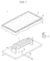
- FIG. 1 is an exploded perspective view of a fabrication device according to this embodiment.
- the fabrication device 1 comprises a frame 2, a tool 3, a holding section 4, a highly stretchable sheet 5, a securing jig 6, and an evacuation device (not shown in the figure).
- the frame 2 is composed of a material typically used for composite material fabrication jigs.
- the material include aluminum alloys, steel alloys such as stainless steel or invar, and fiber-reinforced composite materials.
- the tool 3 is an aluminum alloy, a steel alloy such as stainless steel or invar, or a fiber-reinforced composite material having a predetermined shape that corresponds with the fabricated product.
- the holding section 4 can hold the tool 3 with a gap maintained between the tool 3 and the frame 2, namely in a state where the tool 3 floats above the frame 2.
- the holding section 4 is secured to the top of the frame, and the tool 3 is held by mounting both ends of the tool 3 on the holding section 4.
- the highly stretchable sheet 5 is secured to the frame 2 by the securing jig 6.
- the highly stretchable sheet 5 is formed from a material which, when secured with the securing jig 6 so as to cover the tool 3 and the prepreg 7, is able to apply tension from the portion that contacts the prepreg 7 down to the edges of the highly stretchable sheet, thereby forming an internal enclosed space.
- the highly stretchable sheet 5 has a level of ductility that enables the sheet to cover the exterior periphery of the tool when the inside of the enclosed space is evacuated using an evacuation device.
- a silicone sheet having a breaking elongation of not less than 700%, a rupture strength of not less than 9.0 MPa and a thickness of 1.6 mm can be used.
- a silicone sheet sandwiched from above and below between rigid frames 8 is used as the highly stretchable sheet 5.
- the securing jig 6 is composed of C-clamps or the like. A plurality of these C-clamps are provided so that when the highly stretchable sheet 5 is secured to the frame 2, the interior becomes an enclosed space.
- the evacuation device may be a vacuum pump or the like that is capable of evacuating the inside of the aforementioned enclosed space down to a desired degree of vacuum.
- a vacuum pump or the like that is capable of evacuating the inside of the aforementioned enclosed space down to a desired degree of vacuum.
- an oil-sealed rotary vacuum pump having an ultimate pressure of 2.7 Pa (catalog value) and a design exhaust speed of 1,600 L/min (catalog value) can be used.
- the evacuation device is connected to the inside of the enclosed space by an evacuation hose 10 connected to a through-hole 9 provided in the frame.
- the connection position of the evacuation device is set appropriately in accordance with factors such as the shape and size of the fabricated product.
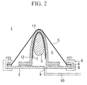
- Fig. 2 illustrates a cross-sectional view of the fabrication device 1 prior to wrapping the prepreg 7 around the tool 3.
- the tool 3 is positioned on top of the frame 2.
- the tool 3 is held with a gap maintained between the tool 3 and the frame 2.
- the ends of the tool 3 are held by the holding section (not shown in the figure) so that the tool 3 floats above the frame 2.
- the tool 3 is preferably positioned so that the top portion 11 of the tool forms a convex surface in a direction following the outer periphery of the tool.
- the tool 3 is preferably positioned so that the surface of the tool positioned opposite the frame 2 has a convex shape in a direction following the outer periphery of the tool.
- the top portion 11 indicates the portion located on the opposite side to the frame 2. It is particularly desirable that the tool 3 is positioned so that the most tapered portion of the tool functions as the top portion.
- the tool surface may be coated with an appropriate release agent.
- a prepreg 7 formed from a fiber-reinforced resin is placed on top of the tool 3.
- the prepreg 7 is formed from a composite material containing mainly a carbon fiber-reinforced plastic (CFRP).
- CFRP carbon fiber-reinforced plastic
- the highly stretchable sheet 5 is disposed so as to cover the tool 3 and the prepreg 7 from above the prepreg 7, and bagging is performed.
- the rigid frames 8 provided at the edges of the highly stretchable sheet 5 are aligned with the edges of the frame 2, and the two are then secured using C-clamps 6.
- an enclosed space S surrounded by the frame 2 and the highly stretchable sheet 5 is formed.
- the tool 3 and the prepreg 7 are housed inside this enclosed space S.
- the surface area inside the rigid frames 8 of the highly stretchable sheet 5 is substantially the same as the surface area of the frame 2.
- the highly stretchable sheet 5 is stretched compared with the state prior to securing by an amount equivalent to the tool 3 and the prepreg 7 housed inside the enclosed space S.
- tension is applied to the highly stretchable sheet 5 with the top portion of the prepreg 7 and the portions secured by the C-clamps 6 acting as support points.
- a member 12 for ensuring an air flow path and ensuring favorable releasability may be disposed between the prepreg 7 and the highly stretchable sheet 5.
- the member for ensuring an air flow path include a polyester vent mat or a peel ply or the like.
- the member for ensuring favorable releasability include release films and the like.
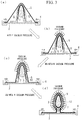
- Fig. 3 is a flow diagram illustrating the application of vacuum pressure during wrapping of the prepreg 7 around the tool 3.
- the rigid frames 8, the evacuation hole 9 and the evacuation hose 10 are not shown.
- Fig. 3(a) illustrates the state prior to application of vacuum pressure.
- the edges of the prepreg 7 are illustrated hanging down in the direction of gravity, but these edges may also be held in place temporarily, for example by an operator manually pressing the edges against the tool 3.
- a vacuum pressure is first applied to the portion where the highly stretchable sheet 5 contacts the top portion of the tool 3 (prepreg) ( Fig. 3(b) ).
- vacuum pressure is sequentially applied to lower portions of the tool 3 (nearer the frame) ( Fig. 3(c) ), until finally, the prepreg 7 is wrapped tightly around the periphery of the tool 3 ( Fig. 3(d) ).
- evacuation of the inside of the enclosed space S is performed without heating the prepreg 7.
- the vacuum pressure is applied and the prepreg 7 is wrapped with the resin contained within the prepreg 7 maintained in a non-fluid state.
- the prepreg 7 can be wrapped tightly onto the tool without any change in the thickness of the prepreg 7.
- Fig. 4 illustrates a cross-sectional view of the fabrication device following wrapping of the prepreg 7 around the tool 3.
- the prepreg 7 is wrapped in a state of tight contact around the tool 3, and the highly stretchable sheet 5 is wrapped around the outer periphery in a more highly stretched state than that prior to evacuation.
- Fig. 5 illustrates an enlarged view of the region A of Fig. 4 .
- a release film 13 Prior to formation of the enclosed space S, a release film 13 is interposed between the edges of the prepreg 7 and the member that acts as the substrate beneath the edges of the prepreg 7 (the tool 3 in the case of Fig. 5 ).
- a film of FEP tetrafluoroethylene-hexafluoropropylene copolymer resin
- the release film 13 may be secured using a spray adhesive or the like.
- the edge portions of the prepreg 7 can be easily peeled from the tool 3. In those cases where surplus portions exist at the edges of the prepreg 7, those surplus portions may be cut as appropriate.
- the steps described above represent one wrapping cycle for the prepreg 7, and the wrapping cycle may be repeated as appropriate to stack multiple layers of the prepreg 7 depending on the fabricated product.
- the orientation of the tool 3 may be altered for each wrapping cycle, thereby shifting the position of the top portion of the tool.
- one layer of the prepreg 7 was wrapped about the tool in each wrapping cycle, but depending on the variety and thickness of the prepreg 7, and the application, shape and size of the fabricated product, a plurality of superimposed layers of the prepreg 7 may be wrapped about the tool 3 in a single wrapping cycle.
- a press jig connected to an elastic member may be provided to prevent the edges of the prepreg 7 from adhering to the underlying substrate.
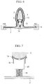
- Fig. 6 illustrates an example of the positioning of a press jig 15 to which an elastic member 14 is connected.
- Fig. 7 illustrates an enlarged view of the region B shown in Fig. 6 .
- Fig. 6 is a diagram illustrating a case in which a second wrapping cycle has been used to wrap a second prepreg 7b on top of the tool 3 having a first prepreg 7a wrapped thereon via a first wrapping cycle.
- the elastic member 14 is secured on the surface of the frame 2 in a position where the tool 3 and the frame 2 oppose one another.
- the elastic member 14 exhibits elasticity in the direction leading from the frame 2 toward the tool 3, and is formed, for example, using a spring or the like.
- the press jig 15 is connected to the top of the spring.
- the press jig 15 can use the reactive force of the spring to press against the surface of the tool 3 that faces the frame 2.
- the sequence in which vacuum pressure is applied to the prepreg 7 can be controlled.
- the prepreg 7 can be wrapped tightly about the tool 3 with minimal initial capital investment.
- a heat and pressure treatment is performed to cure the resin of the prepreg. Subsequently, the product is released appropriately from the tool to obtain a composite material hollow part. According to the embodiment described above, because the generation of wrinkles can be reduced, the quality of the composite material hollow part can be improved.
Landscapes
- Engineering & Computer Science (AREA)
- Mechanical Engineering (AREA)
- Chemical & Material Sciences (AREA)
- Composite Materials (AREA)
- Casting Or Compression Moulding Of Plastics Or The Like (AREA)
- Moulding By Coating Moulds (AREA)
- Blow-Moulding Or Thermoforming Of Plastics Or The Like (AREA)
- Moulds For Moulding Plastics Or The Like (AREA)
Claims (8)
- Ein Verfahren zum Herstellen eines hohlen Teils aus Verbundwerkstoff, wobei das Verfahren aufweist:Halten eines Werkzeugs (3) auf einem Rahmen (2),Anordnen eines Prepregs (7), das aus einem faserverstärkten Harz gebildet ist, auf dem Werkzeug (3),Abdecken des Werkzeugs (3) und des Prepregs (7) von oberhalb des Prepregs (7) unter Verwendung einer stark dehnbaren Lage (5),Sichern der stark dehnbaren Lage (5) und des Rahmens (2) mit einer Sicherungs-Spannvorrichtung (6), sodass ein Zug auf die stark dehnbare Lage (5) von einem oberen Abschnitt (11) des Prepregs (7) bewirkt, wo die stark dehnbare Lage (5) das Prepreg (7), an der stark dehnbaren Lage (5) und dem Außenumfang sowohl des Werkzeugs (3) als auch des Prepregs (7), zu den Rändern der stark dehnbaren Lage (5), wodurch ein umschlossener Raum (S) gebildet wird, in dessen Innerem das Werkzeug (3) und das Prepreg (7) aufgenommen sind, undanschließendes Evakuieren der Innenseite des umschlossenen Raums (S) unter Anwendung einer Evakuierungsvorrichtung, die mit dem Inneren des umschlossenen Raums (S) verbunden ist, wodurch das Prepreg (7) um das Werkzeug (3) herum gelegt wird, dadurch gekennzeichnet, dass ein Halteabschnitt (4) verwendet wird, der einen Zwischenraum zwischen dem Werkzeug (3) und dem Rahmen (2) aufrechterhält.
- Das Verfahren zum Herstellen eines hohlen Teils aus Verbundwerkstoff gemäß Anspruch 1, wobei
das Werkzeug (3) so positioniert ist oder wird, dass der obere Abschnitt (11) des Prepregs eine konvexe Oberfläche in einer einem Außenumfang des Prepregs (7) folgenden Richtung bildet. - Das Verfahren zum Herstellen eines hohlen Teils aus Verbundwerkstoff gemäß Anspruch 1 oder Anspruch 2, wobei ein Trennfilm (13) zwischen Rändern des Prepregs (7) und einem Element, das als ein darunterliegendes Substrat unter den Rändern des Prepregs (7) wirkt, eingefügt wird.
- Das Verfahren zum Herstellen eines hohlen Teils aus Verbundwerkstoff gemäß Anspruch 1 oder Anspruch 2, wobei
ein elastisches Element (14), das Elastizität in einer Richtung von dem Rahmen (2) zu dem Werkzeug (3) bietet, an dem Rahmen (2) gegenüberliegend dem Werkzeug (3) positioniert wird, und
eine Press-Spannvorrichtung (15), die eine Reaktionskraft des elastischen Elements (14) nutzen kann, um gegen eine Oberfläche des Werkzeugs (3) zu drücken, die dem Rahmen (2) zugewandt ist, auf dem elastischen Element (14) positioniert wird. - Eine Vorrichtung (1) zum Herstellen eines hohlen Teils aus Verbundwerkstoff, wobei die Vorrichtung (1) aufweist:einen Rahmen (2),ein Werkzeug (3) zum Herumlegen eines Prepregs (7), das aus einem faserverstärkten Harz gebildet ist,eine stark dehnbare Lage (5), die das Werkzeug (3) und das Prepreg (7) von oberhalb des Prepregs (7) abdeckt,eine Sicherungs-Spannvorrichtung (6), die die stark dehnbare Lage (5) und den Rahmen (2) so sichert, dass ein Zug auf die stark dehnbare Lage (5) von einem oberen Abschnitt (11) des Prepregs (7) ausgeübt wird, wo die stark dehnbare Lage (5) das Prepreg (7), an der stark dehnbaren Lage (5) und dem Außenumfang sowohl des Werkzeugs (3) als auch des Prepregs (7) zu den Rändern der stark dehnbaren Lage (5), wodurch ein umschlossener Raum (S) gebildet wird, in dessen Innerem das Werkzeug (3) und das Prepreg (7) aufgenommen sind, undeine Evakuierungsvorrichtung, die mit dem Inneren des umschlossenen Raums (S) so verbunden ist, dass sie das Innere des umschlossenen Raums (S) evakuieren kann, gekennzeichnet durch einen Halteabschnitt (4), der das Werkzeug (3) an oder auf dem Rahmen (2) hält, wobei ein Zwischenraum zwischen dem Werkzeug (3) und dem Rahmen (2) eingehalten ist.
- Die Vorrichtung (1) zum Herstellen eines hohlen Teils aus Verbundwerkstoff gemäß Anspruch 5, wobeidas Werkzeug (3) so positioniert ist, dass der obere Abschnitt (11) des Prepregs (7) eine konvexe Oberfläche in einer Richtung, die einem Außenumfang des Prepregs (7) folgt, bildet.
- Die Vorrichtung (1) zum Herstellen eines hohlen Teils aus Verbundwerkstoff gemäß Anspruch 5 oder Anspruch 6, wobeiein Trennfilm (13) zwischen Rändern des Prepregs (7) und einem Element, das als ein darunterliegendes Substrat unter den Rändern des Prepregs (7) wirkt, angeordnet ist.
- Die Vorrichtung (1) zum Herstellen eines hohlen Teils aus Verbundwerkstoff gemäß Anspruch 5 oder Anspruch 6, ferner mit:einem elastischen Element (14), das an oder auf dem Rahmen (2) gegenüberliegend dem Werkzeug (3) positioniert ist und Elastizität in einer Richtung von dem Rahmen (2) zu dem Werkzeug (3) bietet,und einer Press-Spannvorrichtung (15), die an oder auf dem elastischen Element (14) angeordnet ist und eine Reaktionskraft des elastischen Elements (14) nutzen kann, um gegen eine Oberfläche des Werkzeugs (3), die dem Rahmen (2) zugewandt ist, zu drücken.
Applications Claiming Priority (2)
| Application Number | Priority Date | Filing Date | Title |
|---|---|---|---|
| JP2011081255A JP5665630B2 (ja) | 2011-03-31 | 2011-03-31 | 複合材中空部品の成形方法及び成形装置 |
| PCT/JP2012/058149 WO2012133534A1 (ja) | 2011-03-31 | 2012-03-28 | 複合材中空部品の成形方法及び成形装置 |
Publications (3)
| Publication Number | Publication Date |
|---|---|
| EP2692500A1 EP2692500A1 (de) | 2014-02-05 |
| EP2692500A4 EP2692500A4 (de) | 2015-04-22 |
| EP2692500B1 true EP2692500B1 (de) | 2016-05-18 |
Family
ID=46931243
Family Applications (1)
| Application Number | Title | Priority Date | Filing Date |
|---|---|---|---|
| EP12764458.1A Not-in-force EP2692500B1 (de) | 2011-03-31 | 2012-03-28 | Formverfahren und formvorrichtung für ein hohles teil eines verbundwerkstoffs |
Country Status (4)
| Country | Link |
|---|---|
| US (1) | US9403302B2 (de) |
| EP (1) | EP2692500B1 (de) |
| JP (1) | JP5665630B2 (de) |
| WO (1) | WO2012133534A1 (de) |
Families Citing this family (4)
| Publication number | Priority date | Publication date | Assignee | Title |
|---|---|---|---|---|
| DE102011119046A1 (de) * | 2011-11-22 | 2013-05-23 | Premium Aerotec Gmbh | Umformen bei der Herstellung eines profilierten Bauteils |
| US8826957B2 (en) * | 2012-08-31 | 2014-09-09 | General Electric Company | Methods and systems for automated ply layup for composites |
| JP6211096B2 (ja) * | 2013-11-28 | 2017-10-11 | 中島ゴム工業株式会社 | 未加硫ゴムを接着対象物にゴム層として定着させる方法 |
| CN109849367A (zh) * | 2019-03-20 | 2019-06-07 | 成都联科航空技术有限公司 | 一种大厚度复合材料裙的加工方法 |
Family Cites Families (14)
| Publication number | Priority date | Publication date | Assignee | Title |
|---|---|---|---|---|
| DE1183353B (de) * | 1960-10-14 | 1964-12-10 | Us Rubber Co | Vakuumtiefziehverfahren zum UEberziehen gepolsterter Werkstuecke mit einem UEberzugsstoff und Vorrichtung zu dessen Durchfuehrung |
| US4878979A (en) * | 1986-04-25 | 1989-11-07 | United Technologies Corporation | Method of reusably sealing a silicone rubber vacuum bag to a mold for composite manufacture |
| JPH0760770A (ja) | 1993-08-25 | 1995-03-07 | Mitsubishi Heavy Ind Ltd | Frp立体成形法 |
| US5939007A (en) * | 1994-08-31 | 1999-08-17 | Sikorsky Aircraft Corporation | Method for manufacture of a fiber reinforced composite spar for rotary wing aircraft |
| GB0014113D0 (en) | 2000-06-10 | 2000-08-02 | Gkn Westland Helicopters Ltd | Improvements in or relating to moulding |
| US6949282B2 (en) * | 2000-07-07 | 2005-09-27 | Delphi Technologies, Inc. | Contoured crushable composite structural members and methods for making the same |
| DE10106208C2 (de) | 2001-02-10 | 2002-12-19 | Aloys Wobben | Windenergieanlage |
| JP2005288785A (ja) * | 2004-03-31 | 2005-10-20 | Toray Ind Inc | プリフォームの製造方法 |
| JP2006007492A (ja) * | 2004-06-23 | 2006-01-12 | Toyota Motor Corp | Frp製プリフォームの製造方法 |
| JP4503538B2 (ja) * | 2005-03-07 | 2010-07-14 | 豊田通商株式会社 | シートパッド補強布の製造方法及び製造装置 |
| RU2443555C2 (ru) | 2006-09-29 | 2012-02-27 | Торэй Индастриз, Инк. | Формовочно-литьевое устройство и способ производства преформ и армированных волокном пластмасс с помощью формовочно-литьевого устройства |
| ITTO20070423A1 (it) * | 2007-06-14 | 2008-12-15 | Alenia Aeronautica Spa | Procedimento ed attrezzatura di polimerizzazione per la fabbricazione di travi di materiale composito aventi una sezione trasversale a forma di j. |
| JP2009051112A (ja) * | 2007-08-28 | 2009-03-12 | Toray Ind Inc | ドレープ成形方法 |
| EP2123431B1 (de) | 2008-05-21 | 2011-03-02 | Siemens Aktiengesellschaft | Verfahren zur Herstellung eines Verbundstoffes |
-
2011
- 2011-03-31 JP JP2011081255A patent/JP5665630B2/ja active Active
-
2012
- 2012-03-28 US US13/981,204 patent/US9403302B2/en not_active Expired - Fee Related
- 2012-03-28 WO PCT/JP2012/058149 patent/WO2012133534A1/ja not_active Ceased
- 2012-03-28 EP EP12764458.1A patent/EP2692500B1/de not_active Not-in-force
Non-Patent Citations (1)
| Title |
|---|
| None * |
Also Published As
| Publication number | Publication date |
|---|---|
| WO2012133534A1 (ja) | 2012-10-04 |
| EP2692500A1 (de) | 2014-02-05 |
| US20130299072A1 (en) | 2013-11-14 |
| JP5665630B2 (ja) | 2015-02-04 |
| US9403302B2 (en) | 2016-08-02 |
| EP2692500A4 (de) | 2015-04-22 |
| JP2012213935A (ja) | 2012-11-08 |
Similar Documents
| Publication | Publication Date | Title |
|---|---|---|
| JP4964961B2 (ja) | 熱可塑性複合材で形成されるパネルを製造する方法 | |
| JP6722369B2 (ja) | ハニカムサンドイッチ複合材の成形方法 | |
| US20080121335A1 (en) | Method for attaching and peeling pressure-sensitive adhesive sheet, and attaching apparatus of pressure-sensitive adhesive sheet and peeling apparatus of pressure-sensitive adhesive sheet | |
| JP4952056B2 (ja) | プリフォームの製造方法およびプリフォームの製造装置 | |
| US9403302B2 (en) | Fabrication method and fabrication device for composite material hollow part | |
| JPH0767704B2 (ja) | 中空複合部材の製造方法 | |
| JP6269496B2 (ja) | 減圧治具及び減圧治具を用いた被加圧物の加圧方法 | |
| US20150368418A1 (en) | Silicone-coated release film with a special vacuum deep drawing capability | |
| WO2008109029A2 (en) | Composite article debulking process | |
| EP2647487A1 (de) | Formvorrichtung und Formverfahren | |
| JP2006219078A (ja) | 航空機用複合体及び航空機の複合体構造部の製造方法 | |
| JP4328579B2 (ja) | ハニカムサンドイッチパネルの製造方法 | |
| US20120279649A1 (en) | A method and a placement tool for the manufacture of a non-crimp fabric | |
| US20180015685A1 (en) | Honeycomb structural body and method of manufacturing honeycomb structural body | |
| JP4648019B2 (ja) | 加圧バッグの製造方法、及び係る加圧バッグを用いた複合材成形品の成形方法 | |
| JP2947867B2 (ja) | 複合材の成形方法および成形型の成形方法 | |
| JPH03143606A (ja) | 樹脂予備含浸ファブリックプライの取扱い方法 | |
| KR101463562B1 (ko) | 섬유강화 복합재 제품 제조방법 | |
| JP2016221865A (ja) | 複合材パイプ及び複合材パイプの製造方法 | |
| JP2004148700A (ja) | 複合材製ラミネートシムとその製作方法 | |
| JP2012016939A (ja) | 複合材成形品の製造方法 | |
| JP2023115678A (ja) | 複合材の成形方法及び複合材の成形治具 | |
| JP4464208B2 (ja) | ハニカムサンドイッチパネルの製造方法 | |
| JP2005305673A (ja) | 繊維強化積層材およびその製造方法 | |
| JP7362852B2 (ja) | プリプレグの処理方法及び成形品の製造方法 |
Legal Events
| Date | Code | Title | Description |
|---|---|---|---|
| PUAI | Public reference made under article 153(3) epc to a published international application that has entered the european phase |
Free format text: ORIGINAL CODE: 0009012 |
|
| 17P | Request for examination filed |
Effective date: 20130725 |
|
| AK | Designated contracting states |
Kind code of ref document: A1 Designated state(s): AL AT BE BG CH CY CZ DE DK EE ES FI FR GB GR HR HU IE IS IT LI LT LU LV MC MK MT NL NO PL PT RO RS SE SI SK SM TR |
|
| DAX | Request for extension of the european patent (deleted) | ||
| RA4 | Supplementary search report drawn up and despatched (corrected) |
Effective date: 20150324 |
|
| RIC1 | Information provided on ipc code assigned before grant |
Ipc: B29C 43/56 20060101ALI20150318BHEP Ipc: B29L 22/00 20060101ALI20150318BHEP Ipc: B29K 105/08 20060101ALI20150318BHEP Ipc: B29C 43/12 20060101AFI20150318BHEP Ipc: B29C 33/40 20060101ALI20150318BHEP |
|
| GRAP | Despatch of communication of intention to grant a patent |
Free format text: ORIGINAL CODE: EPIDOSNIGR1 |
|
| INTG | Intention to grant announced |
Effective date: 20160208 |
|
| GRAS | Grant fee paid |
Free format text: ORIGINAL CODE: EPIDOSNIGR3 |
|
| GRAA | (expected) grant |
Free format text: ORIGINAL CODE: 0009210 |
|
| AK | Designated contracting states |
Kind code of ref document: B1 Designated state(s): AL AT BE BG CH CY CZ DE DK EE ES FI FR GB GR HR HU IE IS IT LI LT LU LV MC MK MT NL NO PL PT RO RS SE SI SK SM TR |
|
| REG | Reference to a national code |
Ref country code: GB Ref legal event code: FG4D |
|
| REG | Reference to a national code |
Ref country code: CH Ref legal event code: EP |
|
| REG | Reference to a national code |
Ref country code: IE Ref legal event code: FG4D Ref country code: AT Ref legal event code: REF Ref document number: 800037 Country of ref document: AT Kind code of ref document: T Effective date: 20160615 |
|
| REG | Reference to a national code |
Ref country code: DE Ref legal event code: R096 Ref document number: 602012018658 Country of ref document: DE |
|
| REG | Reference to a national code |
Ref country code: NL Ref legal event code: MP Effective date: 20160518 |
|
| REG | Reference to a national code |
Ref country code: LT Ref legal event code: MG4D |
|
| PG25 | Lapsed in a contracting state [announced via postgrant information from national office to epo] |
Ref country code: NO Free format text: LAPSE BECAUSE OF FAILURE TO SUBMIT A TRANSLATION OF THE DESCRIPTION OR TO PAY THE FEE WITHIN THE PRESCRIBED TIME-LIMIT Effective date: 20160818 Ref country code: FI Free format text: LAPSE BECAUSE OF FAILURE TO SUBMIT A TRANSLATION OF THE DESCRIPTION OR TO PAY THE FEE WITHIN THE PRESCRIBED TIME-LIMIT Effective date: 20160518 Ref country code: NL Free format text: LAPSE BECAUSE OF FAILURE TO SUBMIT A TRANSLATION OF THE DESCRIPTION OR TO PAY THE FEE WITHIN THE PRESCRIBED TIME-LIMIT Effective date: 20160518 Ref country code: LT Free format text: LAPSE BECAUSE OF FAILURE TO SUBMIT A TRANSLATION OF THE DESCRIPTION OR TO PAY THE FEE WITHIN THE PRESCRIBED TIME-LIMIT Effective date: 20160518 |
|
| REG | Reference to a national code |
Ref country code: AT Ref legal event code: MK05 Ref document number: 800037 Country of ref document: AT Kind code of ref document: T Effective date: 20160518 |
|
| PG25 | Lapsed in a contracting state [announced via postgrant information from national office to epo] |
Ref country code: HR Free format text: LAPSE BECAUSE OF FAILURE TO SUBMIT A TRANSLATION OF THE DESCRIPTION OR TO PAY THE FEE WITHIN THE PRESCRIBED TIME-LIMIT Effective date: 20160518 Ref country code: LV Free format text: LAPSE BECAUSE OF FAILURE TO SUBMIT A TRANSLATION OF THE DESCRIPTION OR TO PAY THE FEE WITHIN THE PRESCRIBED TIME-LIMIT Effective date: 20160518 Ref country code: RS Free format text: LAPSE BECAUSE OF FAILURE TO SUBMIT A TRANSLATION OF THE DESCRIPTION OR TO PAY THE FEE WITHIN THE PRESCRIBED TIME-LIMIT Effective date: 20160518 Ref country code: PT Free format text: LAPSE BECAUSE OF FAILURE TO SUBMIT A TRANSLATION OF THE DESCRIPTION OR TO PAY THE FEE WITHIN THE PRESCRIBED TIME-LIMIT Effective date: 20160919 Ref country code: GR Free format text: LAPSE BECAUSE OF FAILURE TO SUBMIT A TRANSLATION OF THE DESCRIPTION OR TO PAY THE FEE WITHIN THE PRESCRIBED TIME-LIMIT Effective date: 20160819 Ref country code: ES Free format text: LAPSE BECAUSE OF FAILURE TO SUBMIT A TRANSLATION OF THE DESCRIPTION OR TO PAY THE FEE WITHIN THE PRESCRIBED TIME-LIMIT Effective date: 20160518 Ref country code: SE Free format text: LAPSE BECAUSE OF FAILURE TO SUBMIT A TRANSLATION OF THE DESCRIPTION OR TO PAY THE FEE WITHIN THE PRESCRIBED TIME-LIMIT Effective date: 20160518 |
|
| PG25 | Lapsed in a contracting state [announced via postgrant information from national office to epo] |
Ref country code: EE Free format text: LAPSE BECAUSE OF FAILURE TO SUBMIT A TRANSLATION OF THE DESCRIPTION OR TO PAY THE FEE WITHIN THE PRESCRIBED TIME-LIMIT Effective date: 20160518 Ref country code: DK Free format text: LAPSE BECAUSE OF FAILURE TO SUBMIT A TRANSLATION OF THE DESCRIPTION OR TO PAY THE FEE WITHIN THE PRESCRIBED TIME-LIMIT Effective date: 20160518 Ref country code: CZ Free format text: LAPSE BECAUSE OF FAILURE TO SUBMIT A TRANSLATION OF THE DESCRIPTION OR TO PAY THE FEE WITHIN THE PRESCRIBED TIME-LIMIT Effective date: 20160518 Ref country code: SK Free format text: LAPSE BECAUSE OF FAILURE TO SUBMIT A TRANSLATION OF THE DESCRIPTION OR TO PAY THE FEE WITHIN THE PRESCRIBED TIME-LIMIT Effective date: 20160518 Ref country code: RO Free format text: LAPSE BECAUSE OF FAILURE TO SUBMIT A TRANSLATION OF THE DESCRIPTION OR TO PAY THE FEE WITHIN THE PRESCRIBED TIME-LIMIT Effective date: 20160518 |
|
| REG | Reference to a national code |
Ref country code: FR Ref legal event code: PLFP Year of fee payment: 6 |
|
| REG | Reference to a national code |
Ref country code: DE Ref legal event code: R097 Ref document number: 602012018658 Country of ref document: DE |
|
| PG25 | Lapsed in a contracting state [announced via postgrant information from national office to epo] |
Ref country code: SM Free format text: LAPSE BECAUSE OF FAILURE TO SUBMIT A TRANSLATION OF THE DESCRIPTION OR TO PAY THE FEE WITHIN THE PRESCRIBED TIME-LIMIT Effective date: 20160518 Ref country code: PL Free format text: LAPSE BECAUSE OF FAILURE TO SUBMIT A TRANSLATION OF THE DESCRIPTION OR TO PAY THE FEE WITHIN THE PRESCRIBED TIME-LIMIT Effective date: 20160518 Ref country code: BE Free format text: LAPSE BECAUSE OF FAILURE TO SUBMIT A TRANSLATION OF THE DESCRIPTION OR TO PAY THE FEE WITHIN THE PRESCRIBED TIME-LIMIT Effective date: 20160518 Ref country code: AT Free format text: LAPSE BECAUSE OF FAILURE TO SUBMIT A TRANSLATION OF THE DESCRIPTION OR TO PAY THE FEE WITHIN THE PRESCRIBED TIME-LIMIT Effective date: 20160518 |
|
| PLBE | No opposition filed within time limit |
Free format text: ORIGINAL CODE: 0009261 |
|
| STAA | Information on the status of an ep patent application or granted ep patent |
Free format text: STATUS: NO OPPOSITION FILED WITHIN TIME LIMIT |
|
| 26N | No opposition filed |
Effective date: 20170221 |
|
| PG25 | Lapsed in a contracting state [announced via postgrant information from national office to epo] |
Ref country code: SI Free format text: LAPSE BECAUSE OF FAILURE TO SUBMIT A TRANSLATION OF THE DESCRIPTION OR TO PAY THE FEE WITHIN THE PRESCRIBED TIME-LIMIT Effective date: 20160518 |
|
| REG | Reference to a national code |
Ref country code: CH Ref legal event code: PL |
|
| PG25 | Lapsed in a contracting state [announced via postgrant information from national office to epo] |
Ref country code: MC Free format text: LAPSE BECAUSE OF FAILURE TO SUBMIT A TRANSLATION OF THE DESCRIPTION OR TO PAY THE FEE WITHIN THE PRESCRIBED TIME-LIMIT Effective date: 20160518 |
|
| REG | Reference to a national code |
Ref country code: IE Ref legal event code: MM4A |
|
| PG25 | Lapsed in a contracting state [announced via postgrant information from national office to epo] |
Ref country code: LU Free format text: LAPSE BECAUSE OF NON-PAYMENT OF DUE FEES Effective date: 20170328 |
|
| REG | Reference to a national code |
Ref country code: FR Ref legal event code: PLFP Year of fee payment: 7 |
|
| PG25 | Lapsed in a contracting state [announced via postgrant information from national office to epo] |
Ref country code: CH Free format text: LAPSE BECAUSE OF NON-PAYMENT OF DUE FEES Effective date: 20170331 Ref country code: LI Free format text: LAPSE BECAUSE OF NON-PAYMENT OF DUE FEES Effective date: 20170331 Ref country code: IE Free format text: LAPSE BECAUSE OF NON-PAYMENT OF DUE FEES Effective date: 20170328 |
|
| PG25 | Lapsed in a contracting state [announced via postgrant information from national office to epo] |
Ref country code: MT Free format text: LAPSE BECAUSE OF NON-PAYMENT OF DUE FEES Effective date: 20170328 |
|
| PG25 | Lapsed in a contracting state [announced via postgrant information from national office to epo] |
Ref country code: AL Free format text: LAPSE BECAUSE OF FAILURE TO SUBMIT A TRANSLATION OF THE DESCRIPTION OR TO PAY THE FEE WITHIN THE PRESCRIBED TIME-LIMIT Effective date: 20160518 |
|
| PG25 | Lapsed in a contracting state [announced via postgrant information from national office to epo] |
Ref country code: HU Free format text: LAPSE BECAUSE OF FAILURE TO SUBMIT A TRANSLATION OF THE DESCRIPTION OR TO PAY THE FEE WITHIN THE PRESCRIBED TIME-LIMIT; INVALID AB INITIO Effective date: 20120328 |
|
| PG25 | Lapsed in a contracting state [announced via postgrant information from national office to epo] |
Ref country code: BG Free format text: LAPSE BECAUSE OF FAILURE TO SUBMIT A TRANSLATION OF THE DESCRIPTION OR TO PAY THE FEE WITHIN THE PRESCRIBED TIME-LIMIT Effective date: 20160518 |
|
| PG25 | Lapsed in a contracting state [announced via postgrant information from national office to epo] |
Ref country code: CY Free format text: LAPSE BECAUSE OF NON-PAYMENT OF DUE FEES Effective date: 20160518 |
|
| PG25 | Lapsed in a contracting state [announced via postgrant information from national office to epo] |
Ref country code: MK Free format text: LAPSE BECAUSE OF FAILURE TO SUBMIT A TRANSLATION OF THE DESCRIPTION OR TO PAY THE FEE WITHIN THE PRESCRIBED TIME-LIMIT Effective date: 20160518 |
|
| PG25 | Lapsed in a contracting state [announced via postgrant information from national office to epo] |
Ref country code: TR Free format text: LAPSE BECAUSE OF FAILURE TO SUBMIT A TRANSLATION OF THE DESCRIPTION OR TO PAY THE FEE WITHIN THE PRESCRIBED TIME-LIMIT Effective date: 20160518 |
|
| PG25 | Lapsed in a contracting state [announced via postgrant information from national office to epo] |
Ref country code: IS Free format text: LAPSE BECAUSE OF FAILURE TO SUBMIT A TRANSLATION OF THE DESCRIPTION OR TO PAY THE FEE WITHIN THE PRESCRIBED TIME-LIMIT Effective date: 20160918 |
|
| PGFP | Annual fee paid to national office [announced via postgrant information from national office to epo] |
Ref country code: GB Payment date: 20220203 Year of fee payment: 11 Ref country code: DE Payment date: 20220203 Year of fee payment: 11 |
|
| PGFP | Annual fee paid to national office [announced via postgrant information from national office to epo] |
Ref country code: IT Payment date: 20220210 Year of fee payment: 11 Ref country code: FR Payment date: 20220209 Year of fee payment: 11 |
|
| REG | Reference to a national code |
Ref country code: DE Ref legal event code: R119 Ref document number: 602012018658 Country of ref document: DE |
|
| GBPC | Gb: european patent ceased through non-payment of renewal fee |
Effective date: 20230328 |
|
| PG25 | Lapsed in a contracting state [announced via postgrant information from national office to epo] |
Ref country code: GB Free format text: LAPSE BECAUSE OF NON-PAYMENT OF DUE FEES Effective date: 20230328 |
|
| PG25 | Lapsed in a contracting state [announced via postgrant information from national office to epo] |
Ref country code: GB Free format text: LAPSE BECAUSE OF NON-PAYMENT OF DUE FEES Effective date: 20230328 Ref country code: FR Free format text: LAPSE BECAUSE OF NON-PAYMENT OF DUE FEES Effective date: 20230331 Ref country code: DE Free format text: LAPSE BECAUSE OF NON-PAYMENT OF DUE FEES Effective date: 20231003 |
|
| PG25 | Lapsed in a contracting state [announced via postgrant information from national office to epo] |
Ref country code: IT Free format text: LAPSE BECAUSE OF NON-PAYMENT OF DUE FEES Effective date: 20230328 |