EP2692389B1 - Nadelspitzenmechanismus - Google Patents
Nadelspitzenmechanismus Download PDFInfo
- Publication number
- EP2692389B1 EP2692389B1 EP13190710.7A EP13190710A EP2692389B1 EP 2692389 B1 EP2692389 B1 EP 2692389B1 EP 13190710 A EP13190710 A EP 13190710A EP 2692389 B1 EP2692389 B1 EP 2692389B1
- Authority
- EP
- European Patent Office
- Prior art keywords
- needle
- inner housing
- tip
- feature
- housing
- Prior art date
- Legal status (The legal status is an assumption and is not a legal conclusion. Google has not performed a legal analysis and makes no representation as to the accuracy of the status listed.)
- Active
Links
Images


Classifications
-
- A—HUMAN NECESSITIES
- A61—MEDICAL OR VETERINARY SCIENCE; HYGIENE
- A61M—DEVICES FOR INTRODUCING MEDIA INTO, OR ONTO, THE BODY; DEVICES FOR TRANSDUCING BODY MEDIA OR FOR TAKING MEDIA FROM THE BODY; DEVICES FOR PRODUCING OR ENDING SLEEP OR STUPOR
- A61M25/00—Catheters; Hollow probes
- A61M25/01—Introducing, guiding, advancing, emplacing or holding catheters
- A61M25/06—Body-piercing guide needles or the like
- A61M25/0612—Devices for protecting the needle; Devices to help insertion of the needle, e.g. wings or holders
- A61M25/0618—Devices for protecting the needle; Devices to help insertion of the needle, e.g. wings or holders having means for protecting only the distal tip of the needle, e.g. a needle guard
-
- A—HUMAN NECESSITIES
- A61—MEDICAL OR VETERINARY SCIENCE; HYGIENE
- A61M—DEVICES FOR INTRODUCING MEDIA INTO, OR ONTO, THE BODY; DEVICES FOR TRANSDUCING BODY MEDIA OR FOR TAKING MEDIA FROM THE BODY; DEVICES FOR PRODUCING OR ENDING SLEEP OR STUPOR
- A61M25/00—Catheters; Hollow probes
- A61M25/01—Introducing, guiding, advancing, emplacing or holding catheters
- A61M25/06—Body-piercing guide needles or the like
- A61M25/0612—Devices for protecting the needle; Devices to help insertion of the needle, e.g. wings or holders
-
- A—HUMAN NECESSITIES
- A61—MEDICAL OR VETERINARY SCIENCE; HYGIENE
- A61M—DEVICES FOR INTRODUCING MEDIA INTO, OR ONTO, THE BODY; DEVICES FOR TRANSDUCING BODY MEDIA OR FOR TAKING MEDIA FROM THE BODY; DEVICES FOR PRODUCING OR ENDING SLEEP OR STUPOR
- A61M5/00—Devices for bringing media into the body in a subcutaneous, intra-vascular or intramuscular way; Accessories therefor, e.g. filling or cleaning devices, arm-rests
- A61M5/178—Syringes
- A61M5/31—Details
- A61M5/32—Needles; Details of needles pertaining to their connection with syringe or hub; Accessories for bringing the needle into, or holding the needle on, the body; Devices for protection of needles
- A61M5/3205—Apparatus for removing or disposing of used needles or syringes, e.g. containers; Means for protection against accidental injuries from used needles
- A61M5/321—Means for protection against accidental injuries by used needles
- A61M5/322—Retractable needles, i.e. disconnected from and withdrawn into the syringe barrel by the piston
- A61M5/3221—Constructional features thereof, e.g. to improve manipulation or functioning
- A61M2005/3223—Means impeding or disabling repositioning of used needles at the syringe nozzle
- A61M2005/3226—Means impeding or disabling repositioning of used needles at the syringe nozzle with means obstructing or blocking the needle mounting opening
-
- A—HUMAN NECESSITIES
- A61—MEDICAL OR VETERINARY SCIENCE; HYGIENE
- A61M—DEVICES FOR INTRODUCING MEDIA INTO, OR ONTO, THE BODY; DEVICES FOR TRANSDUCING BODY MEDIA OR FOR TAKING MEDIA FROM THE BODY; DEVICES FOR PRODUCING OR ENDING SLEEP OR STUPOR
- A61M5/00—Devices for bringing media into the body in a subcutaneous, intra-vascular or intramuscular way; Accessories therefor, e.g. filling or cleaning devices, arm-rests
- A61M5/178—Syringes
- A61M5/31—Details
- A61M5/32—Needles; Details of needles pertaining to their connection with syringe or hub; Accessories for bringing the needle into, or holding the needle on, the body; Devices for protection of needles
- A61M5/3205—Apparatus for removing or disposing of used needles or syringes, e.g. containers; Means for protection against accidental injuries from used needles
- A61M5/321—Means for protection against accidental injuries by used needles
- A61M5/3243—Means for protection against accidental injuries by used needles being axially-extensible, e.g. protective sleeves coaxially slidable on the syringe barrel
- A61M5/3273—Means for protection against accidental injuries by used needles being axially-extensible, e.g. protective sleeves coaxially slidable on the syringe barrel freely sliding on needle shaft without connection to syringe or needle
Definitions
- This invention relates generally to vascular access devices and associated methods. More specifically, this invention relates to a needle-tip shielding mechanism having an interlock system that allows the shielding mechanism to be selectively coupled to a catheter adapter. The interlock system also allows the shielding mechanism to be selectively released and removed from the adapter with little to no friction between the interlock system and the adapter.
- vascular access devices are used for communicating fluid with the vascular system of patients.
- catheters are used for infusing fluid (e.g., saline solution, medicaments, and/or total parenteral nutrition) into a patient, withdrawing fluids (e.g., blood) from a patient, and/or monitoring various parameters of the patient's vascular system.
- fluid e.g., saline solution, medicaments, and/or total parenteral nutrition
- withdrawing fluids e.g., blood
- Intravenous (IV) catheter assemblies are among the various types of vascular access devices.
- Over-the-needle peripheral IV catheters are a common IV catheter configuration.
- the introducer needle is generally a hypodermic needle coupled to a needle assembly to help guide the needle and to facilitate its cooperation with the catheter.
- At least the inner surface of the distal portion of the catheter tightly engages the outer surface of the needle to prevent peelback of the catheter and, thereby, facilitate insertion of the catheter into the blood vessel.
- the catheter and the introducer needle are often assembled so that the distal tip of the introducer needle extends beyond the distal tip of the catheter.
- the catheter and the needle are often assembled so that, during insertion, the bevel of the needle faces up, away from the patient's skin.
- the catheter and introducer needle are generally inserted at a shallow angle through the patient's skin into a blood vessel.
- Flashback In order to verify proper placement of the needle and/or the catheter within the blood vessel, an operator of catheter assembly often confirms that there is a "flashback" of blood into a flashback chamber associated with the needle assembly. Flashback generally entails the appearance of a small amount of blood, which is visible within the needle assembly or between the needle and the catheter.
- the operator may apply pressure to the blood vessel by pressing down on the patient's skin over the blood vessel, distal to the needle and the catheter. This finger pressure momentarily occludes the vessel, minimizing further blood flow through the needle and the catheter.
- a needle tip cover includes a sleeve or other similar device that is designed to trap/capture the needle tip when the introducer needle is withdrawn from the catheter and the patient. After the needle is withdrawn, the catheter is left in place to provide intravenous access to the patient.
- the separation of the introducer needle assembly from the catheter portions of the catheter assembly presents numerous potential hazards to the operator and others in the area. Indeed, as indicated above, there is a risk of accidental needle sticks if the needle tip is not secured properly in a needle tip cover. Additionally, because the needle tip shield is often frictionally engaged within a catheter adapter, an operator may need to jerk or forcefully pull the needle tip shield from the catheter adapter. This jerking and pulling movement may cause discomfort to the patient.
- the present invention relates to a needle-tip shielding mechanism that allows a needle with a needle feature to be retracted from an unshielded position and be trapped in a shielded position. Additionally, the shielding mechanism is adapted to be removed from a catheter adapter with little to no friction. Accordingly, the described shielding mechanism is configured to significantly limit or prevent accidental needle sticks, to be easily removed from a catheter assembly, and to reduce blood exposure.
- WO 2009/139951 A1 describes a safety clip device for shielding and retaining a tip of a catheter needle.
- the catheter adapter includes a sleeve housing a safety clip, whereby, when the needle is withdrawn from the catheter adapter, the safety clip locks in front of the needle tip and thus retains the needle within the sleeve.
- US 2007/0112305 A1 describes a needle shield for a catheter device. As soon as the needle is drawn into the housing of the catheter device, flaps of a barrier snap in front of the needle and thus blocks movement of the needle to prevent exposure of the needle.
- the present invention relates to a method for using a needle-tip shielding mechanism as defined in claim 1 that is designed to overcome some of the limitations known in the art.
- the shielding mechanism comprises a needle, an inner housing, an outer housing, and a catheter adapter.
- the needle may comprise any needle or cannula that can be used with the described shielding mechanism.
- the needle can comprise a hypodermic needle, such as an IV catheter introducer needle.
- the needle may comprise any component or characteristic that allows it to be used with, and be captured by, the described shielding mechanism.
- the needle comprises a needle feature, such as a crimp feature, a welded ferrule feature, a notched crimp feature, or another needle feature that has a surface that extends laterally past the outer diameter ("OD") of the needle.
- the inner housing comprises an interior space through which the needle extends axially.
- the inner housing comprises a needle-feature capture mechanism.
- the needle-feature capture mechanism may comprise any component that limits the proximal movement of the needle feature within the inner housing
- the needle-feature capture mechanism comprises a needle through hole.
- the needle through hole is sized and shaped to allow the needle, but not the laterally extending surface of the needle feature, to pass therethrough.
- the inner housing comprises a needle-tip capture mechanism.
- the needle-tip capture mechanism comprises a duckbilled tip barrier.
- the tip barrier comprises two flaps that extends proximally into the inner housing. In an example, at least a portion of each flap extends at an acute angle from an interior surface of the inner housing. In this example, each flap is also biased away from the interior surface from which the flap originates. Accordingly, when the needle is in the unshielded position, each flap is biased against the needle. Furthermore, when the needle tip is retracted proximally past a proximal-most end of the flaps, the flaps move to a position that blocks the needle tip from forward movement, preventing it from reemerging distally from the inner housing.
- the outer housing may comprise virtually any suitable component or characteristic that allows the inner housing to translate or slide within the outer housing, while still allowing the shielding mechanism to be used as intended.
- the outer housing comprises a canister that is sized and shaped to slidably receive the inner housing in a manner that allows the inner housing to translate between a distal position and a proximal position within the outer housing.
- the outer housing comprises a proximal stop that prevents the inner housing from moving proximally past a certain point with respect to the outer housing.
- the proximal end of the outer housing comprises a proximal opening through which the needle extends.
- the outer housing comprises an interlock system that allows the outer housing to be selectively and removably coupled to a catheter adapter.
- the outer housing comprises an adapter-interlock feature.
- the interlock feature may be moved into, or from, an engaged position in any suitable manner.
- the inner housing biases the interlock features radially outward into the engaged position.
- the interlock feature is allowed to move radially inward, to an unengaged position.
- the adapter-interlock features may comprise any characteristic that allows them to act as intended.
- the interlock feature comprises an arm that is pivotally attached to the outer housing.
- the arm may be pivotally attached to the outer housing in any suitable manner (e.g., through a notch or perforation between the arm and the outer housing).
- the interlock features each comprise a frictional engagement (e.g., a barb, an undercut, etc.) that is adapted to frictionally/mechanically engage a corresponding surface within the lumen of the catheter adapter.
- the shielding mechanism may comprise any suitable component or characteristic that allows the mechanism to function as intended.
- the shielding mechanism comprises means for biasing the inner housing into the distal position.
- the biasing means comprises an inner-housing detent mechanism that biases the inner housing in the distal position, once the inner housing has been moved to the distal position.
- the detent mechanism may comprise protuberance that catches/engages a portion of the inner housing (e.g., the proximal end of the inner housing), once the inner housing has been moved to the distal position. In such instances, a slight pull in the proximal direction can release the detent mechanism and allow the inner housing to move to the proximal position.
- the proximal opening of the outer shield is enlarged to allow a protuberant feature on the needle or a needle hub to communicate with the inner shield.
- the shielding mechanism is inserted into the inner lumen of the catheter adapter with the inner housing disposed in the proximal position. Once the outer housing is placed in its proper position, the needle is pushed distally so that the protuberant feature on the needle/needle hub communicates with the inner housing and pushes the inner housing into the distal position so the interlock features are forced into the engaged position.
- the shielding mechanism may function in any suitable manner.
- the needle before use, the needle is in the unshielded position and the inner housing is disposed in the distal position.
- the needle is pulled proximally with respect to the inner housing.
- the force e.g., friction
- the inner housing remains higher than the force between the inner housing and the needle until the needle feature contacts the needle-feature capture mechanism.
- the inner housing remains in the distal position.
- the force between the needle and the inner housing becomes greater than the force between the inner housing and the outer housing. Accordingly, the proximal force on the needle causes the inner housing to translate proximally with respect to the outer housing.
- the interlock features are allowed to move to the unengaged position.
- the shielding mechanism can be extracted from the catheter adapter with little to no friction between interlock features and the interior surface of the adapter. Moreover, with the needle tip trapped within the inner housing and the outer housing uncoupled from the catheter adapter, the needle and shielding mechanism can be disposed of safely.
- the present invention relates to a needle-tip shielding mechanism.
- the shielding mechanism allows the needle to be moved from an unshielded position in which the needle tip is exposed from the shielding mechanism, to a shielded position in which the needle tip is both covered by the shielding mechanism and is prevented from emerging from a distal and a proximal end of the mechanism.
- the shielding mechanism comprises an interlock system that allows the shielding mechanism to be selectively coupled to a catheter adapter.
- the interlock system further allows the shielding mechanism to be selectively uncoupled and removed from the adapter with little to no friction between the interlock system and the adapter.
- the shielding mechanism can comprise any component or characteristic that allows it to both trap a needle in the shielded position and to selectively couple and uncouple from a catheter adapter.
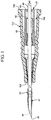
- Figure 1 shows a representative example in which the needle-tip shielding mechanism 20 comprises an inner housing 60, and an outer housing 80. The shielding mechanism operates in conjunction with a needle 40. Additionally, Figure 1 illustrates that the shielding mechanism 20 can be selectively coupled with a catheter adapter 100. To provide a better understanding of the shielding mechanism, the catheter adapter, needle, inner housing, and outer housing are each described below in further detail.
- the shielding mechanism may be used with any suitable catheter adapter, including a catheter adapter for an over-the-needle peripheral IV catheter assembly.
- the catheter adapter may comprise any suitable component.
- Figure 1 shows the catheter adapter 100 comprises a proximal end 102 and a distal end 104 with an inner lumen 106 extending between the two.
- Figure 1 also shows that the proximal end 102 of the adapter 100 is configured to receive the shielding mechanism 20 so the outer housing 80 can be coupled within the adapter's lumen 106.
- the shielding mechanism 20 operates in conjunction with a needle (e.g., needle 40).
- a needle e.g., needle 40
- the terms “needle” or “needles” may refer to virtually any rigid cannula, tube, solid needle (e.g., a trocar), etc. having a sharpened distal tip that is configured to puncture and be inserted into a patient's body.
- Some examples of such needles comprise hypodermic needles, trocars, and cannulae that may expose their operator to the risk of unintended needle-sticking injuries or blood exposure.
- the needle may comprise any suitable type of hypodermic needle, including an introducer needle for use in an IV catheter assembly (e.g., an over-the-needle peripheral IV catheter assembly).
- an introducer needle for use in an IV catheter assembly e.g., an over-the-needle peripheral IV catheter assembly.
- Figure 1 shows the needle comprises an introducer needle 40.
- the introducer needle may have any characteristic that is suitable for use with an IV catheter assembly.
- Figure 1 shows an embodiment in which the introducer needle 40 comprises a sharpened distal tip 42, an inner lumen 44, an elongated tubular portion 46 with a substantially constant outer diameter (“OD") 48, and a needle feature 50.
- OD substantially constant outer diameter
- each of the introducer needle's aforementioned components may comprise any suitable characteristic.
- the distal tip of the needle is selected from a standard bevel, a short bevel, a true short bevel, a bias grind point, a vet point, a lancet point, a deflected point (anti-coring), and another suitable needle point.
- the needle's lumen and elongated tubular portion can be any suitable size.
- the needle may be any length or gauge (e.g., from a 7 to a 33 on the Stubs scale) that allows it to be used as the introducer needle in an IV assembly.
- the needle feature 50 may comprise any suitable object on the needle that is capable of being captured in the inner housing (as described below) in a manner that restricts the feature's proximal movement with respect to the inner housing.
- the needle feature may comprise any surface on the needle that extends laterally past needle's OD and which is adapted to limit the needle's proximal movement with respect to the inner housing.
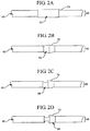
- Figures 2A through 2D illustrate several examples of suitable needle features. Specifically, Figure 2A shows a representative embodiment of a needle 40 in which the needle feature comprises a ferrule 52. Figure 2B shows another representative embodiment in which the needle feature comprises a crimp feature 54. Figures 2C and 2D show additional embodiments in which the needle feature comprises a crimp with a single notch 56 and a plurality of notches 58, respectively.
- the needle feature may have any suitable characteristic.
- the feature may be any suitable shape or size.
- the needle feature may include any component that allows the needle to function as intended and limits the needle's proximal movement with respect to the inner housing.
- Figures 2A through 2D show that the various needle features (e.g., 52, 54, 56, and 58) comprise a proximal engagement 70, or a proximal surface that extends laterally past the needle's OD 48.
- the shielding mechanism also comprises an inner housing.
- the inner housing may comprise any suitable characteristic that allows it to capture and shield the needle tip as well as to translate proximally and/or distally within the outer housing (described below).
- the inner housing can be any suitable size and have any suitable shape through which the needle may pass axially.
- the inner housing can be shorter than the outer housing and have an outer diameter that allows the inner housing to slide within the outer housing.
- the inner housing can be substantially cylindrical, cuboidal, tubular, cage-like, irregular, or have any other suitable shape.
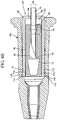
- Figure 3 shows a cross section view of a representative embodiment in which the outer surface of the inner housing 60 has a substantially cylindrical shape.
- the inner housing may also have any suitable component that allows it to trap the needle's sharpened distal tip in a manner that prevents the needle tip from being exposed from either a proximal or a distal end of the inner housing.
- the inner housing comprises a needle-tip capture mechanism that limits the needle tip's distal movement once the needle has been moved to the shielded position.
- the inner housing comprises a needle-feature capture mechanism that acts to capture the needle feature and limit the needle feature's proximal movement when the needle is in the shielded position.
- the inner housing comprises both a needle-tip and a needle-feature capture mechanism.
- the needle-tip capture mechanism may comprise any component that captures the needle's tip and limits the tip's distal movement once the needle has been moved to the shielded position.
- suitable needle-tip capture mechanisms include a needle tip barrier, such as a duckbilled tip barrier, a conventional transverse tip barrier, or another component that is configured to capture the needle's tip and prevent the tip from reemerging distally from the inner housing after the tip has been moved to the shielded position.
- the needle-tip capture mechanism comprises a duckbilled tip barrier.
- the duckbilled tip barrier may comprise any component or characteristic that allows it to prevent the needle tip from reemerging from the inner housing.
- the duckbilled tip barrier comprises at least one flap that extends proximally into the inner housing.
- Figure 3 shows an embodiment in which the duckbilled tip barrier 90 comprises two flaps 92.
- each flap 92 can have any suitable characteristic that allows them to limit the needle tip's distal movement after the needle is moved to the shielded position.
- Figure 3 shows that at least a portion of each flap 92 extends away from an interior surface 64 of the inner housing 60, from which the flap 92 originates, at an acute angle ⁇ .
- each flap is biased away from the interior surface of the inner housing from which the flap originates.
- Figure 3 shows that when the needle 40 is in the unshielded position, each flap 92 is biased away from the interior surface 64 from which it originates towards the needle 40.
- Figures 4A and 4B which respectively illustrate a top plan and a side plan cutaway view of the shielding mechanism 20, show that once the needle tip 42 is pulled proximally past a proximal-most end 94 of the flaps 92, the flaps 92 are allowed to bias against each other in a manner that blocks the needle tip 42 and prevents it from being moved distally out of the inner housing 60.
- Figure 4B illustrates that the proximal end 94 of one or more flaps 92 is broad enough to extend laterally past the OD 48 of the needle 40.
- the flaps can prevent the needle from circumventing the flaps when the needle is twisted.
- the feature capture mechanism may comprise any suitable component or characteristic that allows the capture mechanism to limit the needle feature's proximal movement with respect to the inner housing.
- the needle-feature capture mechanism may comprise a needle through hole (e.g., a conventional washer feature) or any other suitable surface that is adapted to contact the proximal engagement of the needle feature and prevent the needle feature from moving proximally past that surface.
- Figure 4B shows a representative embodiment in which the needle-feature capture mechanism comprises a needle through hole 96 that is sized and shaped to allow the needle 40, but not the proximal engagement 70 of the needle feature 54, to pass therethrough.
- the port may have any suitable characteristic.
- the needle through hole is configured to wipe or squeegee fluids (e.g., blood) from the OD of the needle as the needle is pulled proximally through the needle through hole.
- the inner housing may further reduce the risk of blood exposure.
- this squeegee effect may be provided in any suitable manner.
- the needle through hole may comprise a rubber, plastic, elastomeric, or other similar ring that is capable of wiping blood from the needle.
- the shielding mechanism further comprises an outer housing.
- the outer housing may have any suitable component or characteristic that allows the inner housing to translate within the outer housing and which also allows the outer housing to be selectively and releasably coupled to a catheter adapter.
- Figure 4B shows the outer housing 80 comprises a sleeve with an inner space 82 that is sized and shaped to allow the inner housing 60 to translate between a distal position (as shown in Figure 4B ) and a proximal position (as shown in Figure 5 ) within the outer housing 80.
- Figure 4B shows the outer housing 80 comprises a proximal stop 84, or any suitable surface that prevents inner housing 60 from being removed proximally from the outer housing 80.
- Figure 4B shows an embodiment in which the outer housing 80 comprises a proximal opening 86 through which the needle 40 extends.
- the outer housing can comprise any component or characteristic that allows outer housing to be selectively coupled to and uncoupled from a catheter adapter (discussed below).
- the outer housing comprises an adapter-interlock feature.
- the outer housing may comprise any suitable number of interlock features, including, but not limited to, 1, 2, 3, 4, 5, 6, or more.
- Figure 4B shows a representative embodiment in which the outer housing comprises 2 adapter-interlock features 110.
- each adapter-interlock feature may comprise any characteristic that allows them to selectively couple and uncouple the shielding mechanism from a catheter adapter.
- each adapter-interlock feature comprises an arm that is pivotally attached to the outer housing (i.e., extending as a cantilever from the housing).
- each arm may be pivotally attached to the outer housing in any suitable manner, including through the use of a notch, a hinge, a perforated edge, or any other connection between the interlock feature and the outer housing that allows the interlock feature to pivot with respect to the outer housing.
- Figure 4B illustrates an embodiment in which a notch 112 pivotally connects the arm 110 to the outer housing 80.
- one or more of the adapter-interlock features comprises a frictional engagement that is configured to frictionally or mechanically engage a corresponding surface within an inner lumen of a catheter adapter.
- suitable frictional engagements comprise one or more protuberances, barbs, undercuts, and the like.
- Figure 4B shows an embodiment in which the interlock features 110 comprise a protuberance 114 that fits into interlock-feature mating component (e.g., undercut 116) within the catheter adapter 100.
- the adapter-interlock features may function in any suitable manner.
- the adapter-interlock features articulate with the inner housing to form an interlock system.
- the interlock system may function in any suitable manner.
- the interlock features may be moved into an engaged position in any suitable manner.
- the term engaged position may refer to a position in which the interlock features would couple the outer housing to a catheter adapter if the outer housing were properly seated in the adapter.
- Figure 4B shows that when the inner housing 60 is in the distal position, the inner housing 60 biases the interlock features 110 radially outward into the engaged position.
- distal position may refer to any position in which the inner housing is disposed in a location that biases the interlock features radially outward to the engaged position.
- the adapter-interlock features may be released from the engaged position in any suitable manner.
- Figure 5 shows that the interlock features 110 are released from the engaged position into an unengaged position (as represented by the arrows 118) when the inner housing 60 is moved to the proximal position.
- the term proximal position may refer to any position in which the inner housing is located in a position that allows the interlock features to pivot in towards a longitudinal axis (e.g., axis 120) of the outer housing.
- the described shielding mechanism may comprise any additional component or characteristic that allows the mechanism to fulfill its intended purposes.
- the needle can comprise a conventional notch for flashback confirmation.
- the shielding mechanism comprises means for biasing the inner housing in the distal position.
- the biasing means may comprise any component or characteristic that exerts a force to push or maintain the inner housing to the distal position, while still allowing the inner housing to move between the distal and the proximal position.
- suitable biasing means include friction between the inner housing and the outer housing, an inner-housing detent mechanism, a needle or needle hub that is configured to bias the inner housing into the distal position, or any other component or mechanism that tends to bias the inner housing into the distal position.
- the biasing means may function in any suitable manner.
- the outer housing may be configured (e.g., sized and shaped) so that a force (e.g., friction) between the inner housing and the outer housing is greater than the force (e.g., friction) between the inner housing and the needle until the needle feature contacts the needle-feature capture mechanism.
- a force e.g., friction
- the needle when the needle is pulled proximally, the needle is in the unshielded position, and the inner housing is in the distal position, the needle is allowed to translate proximally into the inner housing without causing the inner housing to translate to the proximal position.
- the needle-feature capture mechanism e.g., needle through hole 96
- the force between the needle and the inner housing is greater than the force between the inner housing and the outer housing
- the inner housing is caused to translate to the proximal position (shown in Figure 5 ).
- the detent mechanism may comprise any component that extends between the inner housing and the outer housing in a manner that can cause a force (e.g., friction) to be applied between the inner housing and the outer housing when the inner housing is moved from the distal position.
- the inner and/or the outer housing may comprise a protuberance, an undercut, or another component that extends between the inner and outer housings and applies a force that opposes the movement of the inner housing from the distal position, wherein the force is easily overcome by an operator pulling the needle proximally.
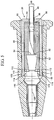
- Figure 6 shows a representative embodiment in which the outer housing 80 comprises a protuberance 88 that applies a small force to the inner housing 60 when the proximal end 66 of the inner housing 60 is pulled against the protuberance 88.
- the biasing means comprises a needle or a needle hub that is configured to bias the inner housing into the distal position
- the biasing means functions in the following manner.
- the proximal opening of the outer housing is enlarged to allow a protuberant feature on the needle or the needle hub to pass distally through the proximal opening. If the inner housing is in the proximal position and the needle is pushed in the distal position, the protuberant feature passes distally through the outer housing's proximal opening, contacts the inner housing, and pushes/biases the inner housing into the distal position. In this manner, the interlock features is moved to the engaged position.
- Figure 7 shows a representative embodiment in which the inner housing 60 is biased by a protuberant feature 122 on a needle hub 124 that extends through the proximal opening 86 of the outer housing 80.
- each of the described components of the shielding mechanism may be made of any suitable material.
- the outer housing and the inner housing may be made of a medical-grade plastic, polymer, metal, metal alloy, ceramic, and/or any other suitable material.
- the outer housing comprises a plastic and the inner housing comprises a metal.
- the outer housing and inner housing can each be molded, stamped, pressed, cut, folded, pieced together, or otherwise be formed to their appropriate shape.
- the inner housing including the needle-tip and needle-feature capture mechanisms, is formed from a single piece of metal (e.g., sheet metal).
- the outer housing is formed through injection molding.
- Figure 8 illustrates a flowchart of an example of a method for making and using the shielding mechanism. While this method may be modified in any suitable manner, Figure 8 shows that after beginning at box 202, the method 200 continues at box 204 by providing a catheter adapter and the shielding mechanism, with the inner housing in the proximal position. Box 206 shows the method continues as the manufacturer seats the shielding mechanism within the inner lumen of the catheter adapter. While the manufacturer may seat the shielding mechanism within the outer housing in any suitable manner, in some embodiments, the manufacturer pushes the outer housing into the adapter and until the adapter-interlock features are aligned with the corresponding interlock-feature mating components within the adapter.
- box 208 shows the method continues as the manufacturer moves the inner housing into the distal position to bias the interlock features into the engaged position. While the inner housing may be moved to the distal position in any suitable manner, in some embodiments, as discussed earlier, the manufacturer uses a protuberant feature on the needle/needle hub to push the inner housing to the distal position.
- box 210 shows the method continues as the operator (e.g., a clinician) uses the catheter assembly by puncturing a patient's skin and blood vessel.
- This puncturing can be performed in any suitable manner, including through a traditional needle placement technique or a hooded technique.
- the operator punctures the patient's skin and blood vessel with the needle and inserts the needle and catheter into the patient's blood vessel.
- box 212 shows the operator applies pressure to the blood vessel, distal to the distal tip of the catheter, and begins to withdraw the introducer needle from the catheter assembly.
- the needle tip becomes trapped and is prevented from reemerging distally from the shielding mechanism.
- Box 214 shows that as the operator continues to pull the needle proximally, the needle feature (e.g., crimp feature 54) contacts the needle-feature capture mechanism and applies a proximal force to the inner housing. As the operator continues to pull the needle and applies a force sufficient to overcome the optional biasing means, the inner housing is also pulled to the proximal position.
- the needle feature e.g., crimp feature 54
- Box 216 shows that when the inner housing is in the proximal position, the interlock features are released from the engaged position and are allowed to pivot radially inward. Accordingly, the shielding mechanism can be uncoupled from the catheter adapter in a manner that allows the shielding mechanism to be extracted from the adapter with a zero or low-force interlock release.
- box 218 shows the method ends as the needle and shielding mechanism are safely disposed.
- Figure 9 shows a representative embodiment in which the needle tip is trapped within the shielding mechanism 20 so that the shielding mechanism and the needle can be disposed.
- the shielding mechanism may offer several additional benefits.
- the shielding mechanism can be released from the adapter with little to no friction between the mechanism and the adapter (e.g., with a zero to low-force interlock release) the shielding mechanism can be released from the catheter adapter without excessive force or jerking motions, which may cause patient discomfort.
- the shielding mechanism has a simple design, which is inexpensive and easy to produce.
- the simple design of the shielding mechanism makes the mechanism easy to use.
- the shielding mechanism can be sized to fit within the inner lumen of the catheter adapter.
Landscapes
- Health & Medical Sciences (AREA)
- Life Sciences & Earth Sciences (AREA)
- Biophysics (AREA)
- Pulmonology (AREA)
- Engineering & Computer Science (AREA)
- Anesthesiology (AREA)
- Biomedical Technology (AREA)
- Heart & Thoracic Surgery (AREA)
- Hematology (AREA)
- Animal Behavior & Ethology (AREA)
- General Health & Medical Sciences (AREA)
- Public Health (AREA)
- Veterinary Medicine (AREA)
- Infusion, Injection, And Reservoir Apparatuses (AREA)
- Surgical Instruments (AREA)
Claims (4)
- Verfahren zur Verwendung eines Nadelspitzenschutzmechanismus (20), wobei das Verfahren umfasst:Bereitstellen eines Nadelspitzenschutzmechanismus (20) mit:einem Außengehäuse (80) mit einem Adapterverriegelungsmerkmal (110) und einer proximalen Öffnung (86);einem Innengehäuse (60) mit einem Nadelmerkmal-Erfassungsmechanismus und einem Nadelspitzen-Erfassungsmechanismus, wobei der Nadelspitzen-Erfassungsmechanismus eine entenschnabelförmige Spitzen-Barriere (92) mit zwei Laschen (92) aufweist, die sich proximal in das Innengehäuse (60) erstrecken, wobei das Innengehäuse (60) in dem Außengehäuse (80) gleitbar zwischen einer ersten Position, in der das Adapterverriegelungsmerkmal (110) in eine Eingriffsposition vorgespannt ist, und einer zweiten Position bewegbar ist, in der eine Bewegung des Adapterverriegelungsmerkmals (110) in eine Nichteingriffsposition (110) zugelassen wird; undeiner Nadel (40), die sich in das Innengehäuse (60) erstreckt, wobei die Nadel (40) ein Nadelmerkmal (54) und eine Spitze (42) aufweist, wobei die beiden Laschen (92) derart konfiguriert sind, dass sie in einer Weise zueinander hin vorgespannt sind, mittels derer die Spitze (42) der Nadel (40) blockiert wird; undeinem Nadelansatz (124), der mit der Nadel (40) gekoppelt ist, wobei die Nadel (40) oder der Nadelansatz (124) ein Vorsprungsmerkmal (122) aufweisen; undDrücken der Nadel (40) distal derart, dass das Vorsprungsmerkmal (122) durch die proximale Öffnung (86) des Außengehäuses (80) hindurchtritt, das Innengehäuse (60) kontaktiert und das Innengehäuse (60) in die erste Position bewegt.
- Verfahren nach Anspruch 1, bei dem das Adapterverriegelungsmerkmal (110) einen Arm aufweist, der schwenkbar mit dem Außengehäuse (80) verbunden ist.
- Verfahren nach Anspruch 1, bei dem der Nadelspitzenschutzmechanismus (20) ferner einen Innengehäuserückhaltemechanismus aufweist, der das Innengehäuse (60) in die erste Position vorspannt.
- Verfahren nach Anspruch 1, bei dem:
der Nadelspitzen-Erfassungsmechanismus eine Nadelspitzenbarriere aufweist und der Nadelmerkmal-Erfassungsmechanismus ein Nadeldurchtrittsloch aufweist.
Applications Claiming Priority (3)
| Application Number | Priority Date | Filing Date | Title |
|---|---|---|---|
| US12/407,182 US8936575B2 (en) | 2009-03-19 | 2009-03-19 | Cannula-tip shielding mechanism |
| EP10709132.4A EP2408507B2 (de) | 2009-03-19 | 2010-03-10 | Nadelspitzenschutzmechanismus |
| PCT/US2010/026833 WO2010107645A1 (en) | 2009-03-19 | 2010-03-10 | Needle-tip shielding mechanism |
Related Parent Applications (2)
| Application Number | Title | Priority Date | Filing Date |
|---|---|---|---|
| EP10709132.4A Division EP2408507B2 (de) | 2009-03-19 | 2010-03-10 | Nadelspitzenschutzmechanismus |
| EP10709132.4A Division-Into EP2408507B2 (de) | 2009-03-19 | 2010-03-10 | Nadelspitzenschutzmechanismus |
Publications (2)
| Publication Number | Publication Date |
|---|---|
| EP2692389A1 EP2692389A1 (de) | 2014-02-05 |
| EP2692389B1 true EP2692389B1 (de) | 2018-10-24 |
Family
ID=42198789
Family Applications (2)
| Application Number | Title | Priority Date | Filing Date |
|---|---|---|---|
| EP10709132.4A Active EP2408507B2 (de) | 2009-03-19 | 2010-03-10 | Nadelspitzenschutzmechanismus |
| EP13190710.7A Active EP2692389B1 (de) | 2009-03-19 | 2010-03-10 | Nadelspitzenmechanismus |
Family Applications Before (1)
| Application Number | Title | Priority Date | Filing Date |
|---|---|---|---|
| EP10709132.4A Active EP2408507B2 (de) | 2009-03-19 | 2010-03-10 | Nadelspitzenschutzmechanismus |
Country Status (9)
| Country | Link |
|---|---|
| US (1) | US8936575B2 (de) |
| EP (2) | EP2408507B2 (de) |
| JP (1) | JP5603406B2 (de) |
| CN (1) | CN102413864B (de) |
| AU (1) | AU2010226186B2 (de) |
| BR (1) | BRPI1012701B1 (de) |
| CA (1) | CA2755370C (de) |
| ES (2) | ES2443828T5 (de) |
| WO (1) | WO2010107645A1 (de) |
Families Citing this family (46)
| Publication number | Priority date | Publication date | Assignee | Title |
|---|---|---|---|---|
| JP4994775B2 (ja) | 2006-10-12 | 2012-08-08 | 日本コヴィディエン株式会社 | 針先保護具 |
| US8257322B2 (en) † | 2010-06-02 | 2012-09-04 | Smiths Medical Asd, Inc. | Tip protector for a safety catheter |
| US8764711B2 (en) * | 2011-02-28 | 2014-07-01 | Injectimed, Inc. | Needle guard |
| US8486024B2 (en) | 2011-04-27 | 2013-07-16 | Covidien Lp | Safety IV catheter assemblies |
| BR112014000197B1 (pt) * | 2011-07-05 | 2021-03-23 | Shl Medical Ag | Conjunto removedor de revestimento de agulha |
| EP2760521B1 (de) | 2011-09-26 | 2016-01-06 | Covidien LP | Sicherheits-iv-katheter und nadelanordnung |
| US8628497B2 (en) | 2011-09-26 | 2014-01-14 | Covidien Lp | Safety catheter |
| WO2013056223A1 (en) | 2011-10-14 | 2013-04-18 | Covidien Lp | Safety iv catheter assembly |
| EP3135333B1 (de) * | 2011-11-08 | 2018-08-22 | Poly Medicure Limited | Intravenöser katheter |
| JP2013172803A (ja) * | 2012-02-24 | 2013-09-05 | Masanori Saeki | 製剤注入具 |
| JP5999415B2 (ja) * | 2012-06-01 | 2016-09-28 | 株式会社ジェイ・エム・エス | 留置針装置 |
| MX373338B (es) * | 2013-07-11 | 2020-05-13 | Becton Dickinson Co | Mecanismo de captura que cuenta con una cánula bidireccional. |
| US9687633B2 (en) * | 2013-12-04 | 2017-06-27 | B. Braun Melsungen Ag | Safety needle devices and related methods |
| US9555221B2 (en) * | 2014-04-10 | 2017-01-31 | Smiths Medical Asd, Inc. | Constant force hold tip protector for a safety catheter |
| EP4563181A3 (de) | 2015-01-30 | 2025-08-13 | ICU Medical, Inc. | Lösbare katheternabenhalterung |
| US20160220805A1 (en) | 2015-01-30 | 2016-08-04 | Smiths Medical Asd, Inc. | Intravenous catheter assembly design |
| EP3277865A1 (de) * | 2015-04-01 | 2018-02-07 | Novo Nordisk A/S | Galvanisierte nadelkanüle |
| WO2018081632A1 (en) | 2016-10-27 | 2018-05-03 | C.R. Bard, Inc. | Intraosseous access device |
| US10946176B2 (en) | 2017-04-06 | 2021-03-16 | Becton, Dickinson And Company | Intravenous catheter assembly with safety clip |
| US10500375B2 (en) | 2017-07-31 | 2019-12-10 | Becton, Dickinson And Company | Catheter assembly |
| WO2019065943A1 (ja) | 2017-09-29 | 2019-04-04 | テルモ株式会社 | カテーテル組立体及び医療用弁 |
| US10828467B2 (en) | 2017-11-30 | 2020-11-10 | Becton, Dickinson And Company | Catheter assembly |
| AU2019282769B2 (en) | 2018-06-08 | 2025-01-23 | Icu Medical, Inc. | Blood sequestration device and method |
| US11642833B2 (en) * | 2018-09-25 | 2023-05-09 | Smiths Medical Asd, Inc. | Cannula bump |
| JP7387717B2 (ja) | 2019-03-28 | 2023-11-28 | テルモ株式会社 | カテーテル組立体 |
| EP3911399B8 (de) | 2019-04-23 | 2024-11-27 | ICU Medical, Inc. | Kathetereinführvorrichtung mit verbesserter drucklasche und spitzenschutzvorrichtung |
| JP7424680B2 (ja) | 2019-09-10 | 2024-01-30 | メドソース・インターナショナル・リミテッド・ライアビリティ・カンパニー | 静脈内カテーテルデバイス |
| US11759235B2 (en) | 2019-09-27 | 2023-09-19 | Bard Access Systems, Inc. | Constant-torque intraosseous access devices and methods thereof |
| CN112568976B (zh) | 2019-09-27 | 2025-08-12 | 巴德阿克塞斯系统股份有限公司 | 用于骨内进入医疗装置的各种操作机构及其方法 |
| CN212879457U (zh) | 2019-09-27 | 2021-04-06 | 巴德阿克塞斯系统股份有限公司 | 自动推进骨内进入装置和骨内进入装置 |
| WO2021062215A1 (en) | 2019-09-27 | 2021-04-01 | Bard Access Systems, Inc. | Step needle for intraosseous access device |
| EP4044944B1 (de) * | 2019-10-16 | 2025-09-24 | Fresenius Kabi Deutschland GmbH | Kanülenvorrichtung |
| WO2021141755A1 (en) * | 2020-01-07 | 2021-07-15 | Gyrus Acmi, Inc, D/B/A Olympus Surgical Technologies America | One-piece elevator for a duodenoscope |
| US12167869B2 (en) | 2020-02-28 | 2024-12-17 | Bard Access Systems, Inc. | Flexible intraosseous obturator |
| US12005244B2 (en) | 2020-03-27 | 2024-06-11 | Medivena Sp. Z O.O. | Needle-based device based on direct wing-based coupling of a needle shield to a barrel thereof and safety mechanism implemented therein |
| CN113520512B (zh) | 2020-04-21 | 2026-01-02 | 巴德阿克塞斯系统股份有限公司 | 可重复使用的推动启动式骨内进入装置 |
| CN215606058U (zh) | 2020-06-03 | 2022-01-25 | 巴德阿克塞斯系统股份有限公司 | 配置用于与骨内进入系统一起使用的闭塞器组件 |
| US11980727B2 (en) | 2020-06-10 | 2024-05-14 | Becton, Dickinson And Company | Needle protection device and related systems and methods |
| US12226123B2 (en) | 2020-07-17 | 2025-02-18 | Bard Access Systems, Inc. | Safety mechanism |
| CN114098918B (zh) | 2020-08-25 | 2025-12-12 | 巴德阿克塞斯系统股份有限公司 | 成角度的骨内进入系统 |
| EP4203821B1 (de) | 2020-09-01 | 2025-10-29 | Bard Access Systems, Inc. | Zurückziehbares intraossäres zugangssystem |
| CN215839325U (zh) | 2020-09-09 | 2022-02-18 | 巴德阿克塞斯系统股份有限公司 | 用于骨内进入系统的抽吸设备 |
| CN217960227U (zh) | 2021-02-08 | 2022-12-06 | 巴德阿克塞斯系统股份有限公司 | 骨内进入系统 |
| WO2022172281A1 (en) | 2021-02-10 | 2022-08-18 | Neeraj Gupta | Intravenous cannula |
| US12337123B2 (en) | 2021-05-06 | 2025-06-24 | Medsource Labs, Llc | Safety intravenous cannula |
| US12186497B2 (en) | 2022-01-14 | 2025-01-07 | Medsource International Llc | Intravenous cannula |
Citations (1)
| Publication number | Priority date | Publication date | Assignee | Title |
|---|---|---|---|---|
| US20070112305A1 (en) * | 2005-11-15 | 2007-05-17 | Becton Dickinson And Company | Needle shield to septum interconnect |
Family Cites Families (51)
| Publication number | Priority date | Publication date | Assignee | Title |
|---|---|---|---|---|
| US4511359A (en) * | 1982-09-29 | 1985-04-16 | Manresa, Inc. | Sterile connection device |
| US4952207A (en) * | 1988-07-11 | 1990-08-28 | Critikon, Inc. | I.V. catheter with self-locating needle guard |
| US4964854A (en) * | 1989-01-23 | 1990-10-23 | Luther Medical Products, Inc. | Intravascular catheter assembly incorporating needle tip shielding cap |
| DE69023124T2 (de) † | 1989-02-01 | 1996-11-14 | Sero Guard Corp | Selbsttätiger nadelschutz für eine wegwerfbare, hypodermische spritze. |
| US5458658A (en) * | 1989-02-01 | 1995-10-17 | Sero-Guard Corporation | Positive locking needle-mounted needle guard for needle supported catheters |
| US5135504A (en) * | 1989-07-17 | 1992-08-04 | Mclees Donald J | Needle tip guard |
| US5558651A (en) * | 1990-04-20 | 1996-09-24 | Becton Dickinson And Company | Apparatus and method for a needle tip cover |
| US5085648A (en) * | 1990-09-13 | 1992-02-04 | Becton Dickinson And Company | Dual diameter needle with a smooth transition |
| US5344408A (en) * | 1993-08-06 | 1994-09-06 | Becton, Dickinson And Company | Break-away safety shield for needle cannula |
| US5419766A (en) | 1993-09-28 | 1995-05-30 | Critikon, Inc. | Catheter with stick protection |
| AUPM520694A0 (en) * | 1994-04-20 | 1994-05-12 | Noble House Group Pty Ltd | Protective sheath |
| US6012213A (en) * | 1995-06-07 | 2000-01-11 | Chang; Joseph J. | Method for forming a rib on a cannula for a tip protection device |
| US6629959B2 (en) * | 1996-02-27 | 2003-10-07 | Injectimed, Inc. | Needle tip guard for percutaneous entry needles |
| DE69733473T2 (de) * | 1996-02-27 | 2006-03-16 | Injectimed, Inc., Ventura | Nadelspitzenschutz für subkutaninjektionen |
| US6117108A (en) * | 1997-08-20 | 2000-09-12 | Braun Melsungen Ag | Spring clip safety IV catheter |
| US8211070B2 (en) * | 1997-08-20 | 2012-07-03 | B. Braun Melsungen Ag | Spring clip safety IV catheter |
| US6616630B1 (en) * | 1997-08-20 | 2003-09-09 | B. Braun Melsungen A.G. | Spring clip safety IV catheter |
| US6004294A (en) * | 1998-04-09 | 1999-12-21 | Becton, Dickinson And Company | Catheter and introducer needle assembly with needle shield |
| US6652490B2 (en) * | 1998-04-09 | 2003-11-25 | Becton Dickinson And Company | Catheter and introducer needle assembly with compact needle shield |
| US6379333B1 (en) * | 1998-04-09 | 2002-04-30 | Becton, Dickinson And Company | Catheter and introducer needle assembly with needle shield |
| US6749588B1 (en) * | 1998-04-09 | 2004-06-15 | Becton Dickinson And Company | Catheter and introducer needle assembly with needle shield |
| US6224569B1 (en) † | 1999-09-24 | 2001-05-01 | Becton, Dickinson And Company | Compact needle point shield |
| DE29921084U1 (de) * | 1999-12-01 | 2000-02-17 | B. Braun Melsungen Ag, 34212 Melsungen | Kurzkatheter |
| US6322537B1 (en) * | 1999-12-30 | 2001-11-27 | Ethicon, Inc. | Safety intravenous catheter |
| US6443927B1 (en) * | 2001-02-06 | 2002-09-03 | Daniel J. Cook | Needle enclosing safety catheter |
| US6692471B2 (en) * | 2001-02-16 | 2004-02-17 | Medex, Inc. | Method and apparatus for safety catheter insertion device |
| US6761706B2 (en) * | 2001-04-04 | 2004-07-13 | Patricia B. Vaillancourt | Needle guard |
| DE20106697U1 (de) * | 2001-04-18 | 2001-10-31 | B. Braun Melsungen Ag, 34212 Melsungen | Kathetereinführvorrichtung |
| ITBO20010497A1 (it) * | 2001-07-31 | 2003-01-31 | Delta Med S R L | Dispositivo di protezione per ago-cannula |
| US6663592B2 (en) * | 2001-09-06 | 2003-12-16 | Medex, Inc. | Catheter introducer assembly having safety shielded needle |
| US7354422B2 (en) * | 2001-09-26 | 2008-04-08 | B. Braun Melsungen Ag | Spring launched needle safety clip |
| US6623458B2 (en) * | 2001-09-26 | 2003-09-23 | B. Braun Melsungen, Ag | Spring launched needle safety clip |
| US6652486B2 (en) * | 2001-09-27 | 2003-11-25 | Medex, Inc. | Safety catheter |
| CA2409306C (en) | 2001-10-24 | 2012-05-01 | Becton, Dickinson And Company | Retractable needle assembly |
| US6914212B2 (en) * | 2002-05-01 | 2005-07-05 | Becton Dickinson And Company | Method of making a needle and a needle |
| EP3639881A1 (de) * | 2002-06-20 | 2020-04-22 | Becton, Dickinson and Company | Katheter und einführernadelanordnung mit nadelabschirmung |
| EP2014328B1 (de) * | 2002-06-20 | 2016-10-19 | Becton, Dickinson and Company | Vorrichtung zum Abschirmen der Spitze einer Kathetereinführnadel |
| NZ542584A (en) | 2003-04-08 | 2006-10-27 | Medex Inc | Safety needle and catheter assembly with bent tip area of needle |
| US7291130B2 (en) * | 2003-04-08 | 2007-11-06 | Smiths Medical Asd, Inc. | Safety needle and catheter assembly |
| TWI303175B (en) * | 2004-02-26 | 2008-11-21 | Nipro Corp | Safe indwelling needle |
| FR2867082B1 (fr) * | 2004-03-02 | 2006-05-26 | Vygon | Dispositif a bec basculant pour la mise en place d'une canule dans une veine |
| FR2867081B1 (fr) * | 2004-03-02 | 2006-05-26 | Vygon | Dispositif a organe de securite coulissant pour la mise en place d'une canule dans une veine |
| WO2006062983A1 (en) | 2004-12-07 | 2006-06-15 | Becton Dickinson And Company | Needle capture mechanisms |
| MX2007010943A (es) * | 2005-03-07 | 2008-02-20 | Erskine Medical Llc | Introducto de cateter con proteccion de aguja. |
| US8257313B2 (en) | 2006-08-11 | 2012-09-04 | Becton, Dickinson And Company | Integrated septum and needle tip shield for a catheter assembly |
| US8992483B2 (en) * | 2007-03-27 | 2015-03-31 | Nipro Corporation | Indwelling needle assembly and protector |
| US7828774B2 (en) † | 2008-05-12 | 2010-11-09 | Harding Weston F | Sleeved clip safety |
| US8398597B2 (en) * | 2008-06-17 | 2013-03-19 | Becton, Dickinson And Company | Needle shield and interlock |
| US7785296B2 (en) † | 2008-07-17 | 2010-08-31 | Smiths Medical Asd, Inc. | Needle tip spring protector |
| BRPI0920464B8 (pt) † | 2008-10-03 | 2021-06-22 | Nipro Corp | protetor de ponta de agulha e montagem de agulha permanente |
| US8496623B2 (en) * | 2009-03-02 | 2013-07-30 | Becton, Dickinson And Company | Bi-directional cannula feature capture mechanism |
-
2009
- 2009-03-19 US US12/407,182 patent/US8936575B2/en active Active
-
2010
- 2010-03-10 WO PCT/US2010/026833 patent/WO2010107645A1/en not_active Ceased
- 2010-03-10 BR BRPI1012701A patent/BRPI1012701B1/pt active IP Right Grant
- 2010-03-10 ES ES10709132T patent/ES2443828T5/es active Active
- 2010-03-10 AU AU2010226186A patent/AU2010226186B2/en active Active
- 2010-03-10 EP EP10709132.4A patent/EP2408507B2/de active Active
- 2010-03-10 ES ES13190710T patent/ES2705556T3/es active Active
- 2010-03-10 EP EP13190710.7A patent/EP2692389B1/de active Active
- 2010-03-10 CA CA2755370A patent/CA2755370C/en active Active
- 2010-03-10 JP JP2012500837A patent/JP5603406B2/ja active Active
- 2010-03-10 CN CN201080018478.7A patent/CN102413864B/zh active Active
Patent Citations (1)
| Publication number | Priority date | Publication date | Assignee | Title |
|---|---|---|---|---|
| US20070112305A1 (en) * | 2005-11-15 | 2007-05-17 | Becton Dickinson And Company | Needle shield to septum interconnect |
Also Published As
| Publication number | Publication date |
|---|---|
| US20100241087A1 (en) | 2010-09-23 |
| BRPI1012701A2 (pt) | 2016-03-22 |
| AU2010226186A1 (en) | 2011-10-06 |
| ES2705556T3 (es) | 2019-03-25 |
| CA2755370C (en) | 2017-10-10 |
| EP2408507A1 (de) | 2012-01-25 |
| EP2408507B2 (de) | 2023-04-19 |
| JP2012520737A (ja) | 2012-09-10 |
| JP5603406B2 (ja) | 2014-10-08 |
| ES2443828T5 (es) | 2023-06-20 |
| BRPI1012701B1 (pt) | 2020-01-28 |
| CN102413864A (zh) | 2012-04-11 |
| CA2755370A1 (en) | 2010-09-23 |
| ES2443828T3 (es) | 2014-02-20 |
| EP2408507B1 (de) | 2013-10-30 |
| US8936575B2 (en) | 2015-01-20 |
| CN102413864B (zh) | 2014-07-16 |
| EP2692389A1 (de) | 2014-02-05 |
| WO2010107645A1 (en) | 2010-09-23 |
| AU2010226186B2 (en) | 2015-09-24 |
Similar Documents
| Publication | Publication Date | Title |
|---|---|---|
| EP2692389B1 (de) | Nadelspitzenmechanismus | |
| US12011554B2 (en) | Bi-directional cannula feature capture mechanism | |
| EP2403582B1 (de) | Zweidirektionaler kanülen-greifmechanismus | |
| EP1819385B1 (de) | Nadelerfassungsmechanismen | |
| CA2918037C (en) | Low profile passive protector for an i.v. catheter | |
| WO2009042583A2 (en) | Tip shield for needle stick prevention | |
| CN215740987U (zh) | 静脉装置组件和血管通路装置 | |
| EP3736011B1 (de) | Zweidirektionaler kanülen-greifmechanismus | |
| AU2023206345A1 (en) | Intravenous cannula |
Legal Events
| Date | Code | Title | Description |
|---|---|---|---|
| AC | Divisional application: reference to earlier application |
Ref document number: 2408507 Country of ref document: EP Kind code of ref document: P |
|
| AK | Designated contracting states |
Kind code of ref document: A1 Designated state(s): AT BE BG CH CY CZ DE DK EE ES FI FR GB GR HR HU IE IS IT LI LT LU LV MC MK MT NL NO PL PT RO SE SI SK SM TR |
|
| PUAI | Public reference made under article 153(3) epc to a published international application that has entered the european phase |
Free format text: ORIGINAL CODE: 0009012 |
|
| 17P | Request for examination filed |
Effective date: 20140731 |
|
| RBV | Designated contracting states (corrected) |
Designated state(s): AT BE BG CH CY CZ DE DK EE ES FI FR GB GR HR HU IE IS IT LI LT LU LV MC MK MT NL NO PL PT RO SE SI SK SM TR |
|
| RAP1 | Party data changed (applicant data changed or rights of an application transferred) |
Owner name: BECTON, DICKINSON AND COMPANY |
|
| STAA | Information on the status of an ep patent application or granted ep patent |
Free format text: STATUS: EXAMINATION IS IN PROGRESS |
|
| 17Q | First examination report despatched |
Effective date: 20161213 |
|
| GRAP | Despatch of communication of intention to grant a patent |
Free format text: ORIGINAL CODE: EPIDOSNIGR1 |
|
| STAA | Information on the status of an ep patent application or granted ep patent |
Free format text: STATUS: GRANT OF PATENT IS INTENDED |
|
| INTG | Intention to grant announced |
Effective date: 20180508 |
|
| GRAS | Grant fee paid |
Free format text: ORIGINAL CODE: EPIDOSNIGR3 |
|
| GRAA | (expected) grant |
Free format text: ORIGINAL CODE: 0009210 |
|
| STAA | Information on the status of an ep patent application or granted ep patent |
Free format text: STATUS: THE PATENT HAS BEEN GRANTED |
|
| AC | Divisional application: reference to earlier application |
Ref document number: 2408507 Country of ref document: EP Kind code of ref document: P |
|
| AK | Designated contracting states |
Kind code of ref document: B1 Designated state(s): AT BE BG CH CY CZ DE DK EE ES FI FR GB GR HR HU IE IS IT LI LT LU LV MC MK MT NL NO PL PT RO SE SI SK SM TR |
|
| REG | Reference to a national code |
Ref country code: CH Ref legal event code: EP |
|
| REG | Reference to a national code |
Ref country code: IE Ref legal event code: FG4D |
|
| REG | Reference to a national code |
Ref country code: AT Ref legal event code: REF Ref document number: 1055964 Country of ref document: AT Kind code of ref document: T Effective date: 20181115 |
|
| REG | Reference to a national code |
Ref country code: DE Ref legal event code: R096 Ref document number: 602010054681 Country of ref document: DE |
|
| REG | Reference to a national code |
Ref country code: NL Ref legal event code: MP Effective date: 20181024 |
|
| REG | Reference to a national code |
Ref country code: LT Ref legal event code: MG4D |
|
| REG | Reference to a national code |
Ref country code: AT Ref legal event code: MK05 Ref document number: 1055964 Country of ref document: AT Kind code of ref document: T Effective date: 20181024 |
|
| REG | Reference to a national code |
Ref country code: ES Ref legal event code: FG2A Ref document number: 2705556 Country of ref document: ES Kind code of ref document: T3 Effective date: 20190325 |
|
| PG25 | Lapsed in a contracting state [announced via postgrant information from national office to epo] |
Ref country code: NL Free format text: LAPSE BECAUSE OF FAILURE TO SUBMIT A TRANSLATION OF THE DESCRIPTION OR TO PAY THE FEE WITHIN THE PRESCRIBED TIME-LIMIT Effective date: 20181024 |
|
| PG25 | Lapsed in a contracting state [announced via postgrant information from national office to epo] |
Ref country code: AT Free format text: LAPSE BECAUSE OF FAILURE TO SUBMIT A TRANSLATION OF THE DESCRIPTION OR TO PAY THE FEE WITHIN THE PRESCRIBED TIME-LIMIT Effective date: 20181024 Ref country code: PL Free format text: LAPSE BECAUSE OF FAILURE TO SUBMIT A TRANSLATION OF THE DESCRIPTION OR TO PAY THE FEE WITHIN THE PRESCRIBED TIME-LIMIT Effective date: 20181024 Ref country code: HR Free format text: LAPSE BECAUSE OF FAILURE TO SUBMIT A TRANSLATION OF THE DESCRIPTION OR TO PAY THE FEE WITHIN THE PRESCRIBED TIME-LIMIT Effective date: 20181024 Ref country code: LV Free format text: LAPSE BECAUSE OF FAILURE TO SUBMIT A TRANSLATION OF THE DESCRIPTION OR TO PAY THE FEE WITHIN THE PRESCRIBED TIME-LIMIT Effective date: 20181024 Ref country code: IS Free format text: LAPSE BECAUSE OF FAILURE TO SUBMIT A TRANSLATION OF THE DESCRIPTION OR TO PAY THE FEE WITHIN THE PRESCRIBED TIME-LIMIT Effective date: 20190224 Ref country code: FI Free format text: LAPSE BECAUSE OF FAILURE TO SUBMIT A TRANSLATION OF THE DESCRIPTION OR TO PAY THE FEE WITHIN THE PRESCRIBED TIME-LIMIT Effective date: 20181024 Ref country code: BG Free format text: LAPSE BECAUSE OF FAILURE TO SUBMIT A TRANSLATION OF THE DESCRIPTION OR TO PAY THE FEE WITHIN THE PRESCRIBED TIME-LIMIT Effective date: 20190124 Ref country code: LT Free format text: LAPSE BECAUSE OF FAILURE TO SUBMIT A TRANSLATION OF THE DESCRIPTION OR TO PAY THE FEE WITHIN THE PRESCRIBED TIME-LIMIT Effective date: 20181024 Ref country code: NO Free format text: LAPSE BECAUSE OF FAILURE TO SUBMIT A TRANSLATION OF THE DESCRIPTION OR TO PAY THE FEE WITHIN THE PRESCRIBED TIME-LIMIT Effective date: 20190124 |
|
| PG25 | Lapsed in a contracting state [announced via postgrant information from national office to epo] |
Ref country code: GR Free format text: LAPSE BECAUSE OF FAILURE TO SUBMIT A TRANSLATION OF THE DESCRIPTION OR TO PAY THE FEE WITHIN THE PRESCRIBED TIME-LIMIT Effective date: 20190125 Ref country code: PT Free format text: LAPSE BECAUSE OF FAILURE TO SUBMIT A TRANSLATION OF THE DESCRIPTION OR TO PAY THE FEE WITHIN THE PRESCRIBED TIME-LIMIT Effective date: 20190224 Ref country code: SE Free format text: LAPSE BECAUSE OF FAILURE TO SUBMIT A TRANSLATION OF THE DESCRIPTION OR TO PAY THE FEE WITHIN THE PRESCRIBED TIME-LIMIT Effective date: 20181024 |
|
| REG | Reference to a national code |
Ref country code: DE Ref legal event code: R097 Ref document number: 602010054681 Country of ref document: DE |
|
| PG25 | Lapsed in a contracting state [announced via postgrant information from national office to epo] |
Ref country code: DK Free format text: LAPSE BECAUSE OF FAILURE TO SUBMIT A TRANSLATION OF THE DESCRIPTION OR TO PAY THE FEE WITHIN THE PRESCRIBED TIME-LIMIT Effective date: 20181024 Ref country code: CZ Free format text: LAPSE BECAUSE OF FAILURE TO SUBMIT A TRANSLATION OF THE DESCRIPTION OR TO PAY THE FEE WITHIN THE PRESCRIBED TIME-LIMIT Effective date: 20181024 |
|
| PG25 | Lapsed in a contracting state [announced via postgrant information from national office to epo] |
Ref country code: SK Free format text: LAPSE BECAUSE OF FAILURE TO SUBMIT A TRANSLATION OF THE DESCRIPTION OR TO PAY THE FEE WITHIN THE PRESCRIBED TIME-LIMIT Effective date: 20181024 Ref country code: EE Free format text: LAPSE BECAUSE OF FAILURE TO SUBMIT A TRANSLATION OF THE DESCRIPTION OR TO PAY THE FEE WITHIN THE PRESCRIBED TIME-LIMIT Effective date: 20181024 Ref country code: SM Free format text: LAPSE BECAUSE OF FAILURE TO SUBMIT A TRANSLATION OF THE DESCRIPTION OR TO PAY THE FEE WITHIN THE PRESCRIBED TIME-LIMIT Effective date: 20181024 Ref country code: RO Free format text: LAPSE BECAUSE OF FAILURE TO SUBMIT A TRANSLATION OF THE DESCRIPTION OR TO PAY THE FEE WITHIN THE PRESCRIBED TIME-LIMIT Effective date: 20181024 |
|
| PLBE | No opposition filed within time limit |
Free format text: ORIGINAL CODE: 0009261 |
|
| STAA | Information on the status of an ep patent application or granted ep patent |
Free format text: STATUS: NO OPPOSITION FILED WITHIN TIME LIMIT |
|
| 26N | No opposition filed |
Effective date: 20190725 |
|
| PG25 | Lapsed in a contracting state [announced via postgrant information from national office to epo] |
Ref country code: SI Free format text: LAPSE BECAUSE OF FAILURE TO SUBMIT A TRANSLATION OF THE DESCRIPTION OR TO PAY THE FEE WITHIN THE PRESCRIBED TIME-LIMIT Effective date: 20181024 Ref country code: MC Free format text: LAPSE BECAUSE OF FAILURE TO SUBMIT A TRANSLATION OF THE DESCRIPTION OR TO PAY THE FEE WITHIN THE PRESCRIBED TIME-LIMIT Effective date: 20181024 |
|
| REG | Reference to a national code |
Ref country code: CH Ref legal event code: PL |
|
| PG25 | Lapsed in a contracting state [announced via postgrant information from national office to epo] |
Ref country code: LU Free format text: LAPSE BECAUSE OF NON-PAYMENT OF DUE FEES Effective date: 20190310 |
|
| PG25 | Lapsed in a contracting state [announced via postgrant information from national office to epo] |
Ref country code: IE Free format text: LAPSE BECAUSE OF NON-PAYMENT OF DUE FEES Effective date: 20190310 Ref country code: LI Free format text: LAPSE BECAUSE OF NON-PAYMENT OF DUE FEES Effective date: 20190331 Ref country code: CH Free format text: LAPSE BECAUSE OF NON-PAYMENT OF DUE FEES Effective date: 20190331 |
|
| PG25 | Lapsed in a contracting state [announced via postgrant information from national office to epo] |
Ref country code: TR Free format text: LAPSE BECAUSE OF FAILURE TO SUBMIT A TRANSLATION OF THE DESCRIPTION OR TO PAY THE FEE WITHIN THE PRESCRIBED TIME-LIMIT Effective date: 20181024 |
|
| PG25 | Lapsed in a contracting state [announced via postgrant information from national office to epo] |
Ref country code: MT Free format text: LAPSE BECAUSE OF NON-PAYMENT OF DUE FEES Effective date: 20190310 |
|
| PG25 | Lapsed in a contracting state [announced via postgrant information from national office to epo] |
Ref country code: CY Free format text: LAPSE BECAUSE OF FAILURE TO SUBMIT A TRANSLATION OF THE DESCRIPTION OR TO PAY THE FEE WITHIN THE PRESCRIBED TIME-LIMIT Effective date: 20181024 |
|
| PG25 | Lapsed in a contracting state [announced via postgrant information from national office to epo] |
Ref country code: HU Free format text: LAPSE BECAUSE OF FAILURE TO SUBMIT A TRANSLATION OF THE DESCRIPTION OR TO PAY THE FEE WITHIN THE PRESCRIBED TIME-LIMIT; INVALID AB INITIO Effective date: 20100310 |
|
| PG25 | Lapsed in a contracting state [announced via postgrant information from national office to epo] |
Ref country code: MK Free format text: LAPSE BECAUSE OF FAILURE TO SUBMIT A TRANSLATION OF THE DESCRIPTION OR TO PAY THE FEE WITHIN THE PRESCRIBED TIME-LIMIT Effective date: 20181024 |
|
| PGFP | Annual fee paid to national office [announced via postgrant information from national office to epo] |
Ref country code: ES Payment date: 20250401 Year of fee payment: 16 |
|
| PGFP | Annual fee paid to national office [announced via postgrant information from national office to epo] |
Ref country code: GB Payment date: 20260220 Year of fee payment: 17 |
|
| PGFP | Annual fee paid to national office [announced via postgrant information from national office to epo] |
Ref country code: DE Payment date: 20260219 Year of fee payment: 17 |
|
| PGFP | Annual fee paid to national office [announced via postgrant information from national office to epo] |
Ref country code: BE Payment date: 20260219 Year of fee payment: 17 Ref country code: IT Payment date: 20260219 Year of fee payment: 17 |
|
| PGFP | Annual fee paid to national office [announced via postgrant information from national office to epo] |
Ref country code: FR Payment date: 20260219 Year of fee payment: 17 |