EP2692220A1 - Richtungsblockierungssensor - Google Patents
Richtungsblockierungssensor Download PDFInfo
- Publication number
- EP2692220A1 EP2692220A1 EP12179143.8A EP12179143A EP2692220A1 EP 2692220 A1 EP2692220 A1 EP 2692220A1 EP 12179143 A EP12179143 A EP 12179143A EP 2692220 A1 EP2692220 A1 EP 2692220A1
- Authority
- EP
- European Patent Office
- Prior art keywords
- magnet
- hall effect
- relative motion
- effect sensors
- detecting device
- Prior art date
- Legal status (The legal status is an assumption and is not a legal conclusion. Google has not performed a legal analysis and makes no representation as to the accuracy of the status listed.)
- Granted
Links
- 230000005355 Hall effect Effects 0.000 claims abstract description 45
- 238000001514 detection method Methods 0.000 description 14
- 230000007246 mechanism Effects 0.000 description 11
- 230000000694 effects Effects 0.000 description 6
- 238000000034 method Methods 0.000 description 4
- 230000004044 response Effects 0.000 description 4
- 238000013016 damping Methods 0.000 description 2
- 230000009467 reduction Effects 0.000 description 2
- 230000008901 benefit Effects 0.000 description 1
- 239000004020 conductor Substances 0.000 description 1
- 230000007423 decrease Effects 0.000 description 1
- 230000006866 deterioration Effects 0.000 description 1
- 238000006073 displacement reaction Methods 0.000 description 1
- 238000009429 electrical wiring Methods 0.000 description 1
- 238000005259 measurement Methods 0.000 description 1
- 230000002093 peripheral effect Effects 0.000 description 1
- 230000036316 preload Effects 0.000 description 1
- 230000008569 process Effects 0.000 description 1
Images


Classifications
-
- A—HUMAN NECESSITIES
- A01—AGRICULTURE; FORESTRY; ANIMAL HUSBANDRY; HUNTING; TRAPPING; FISHING
- A01D—HARVESTING; MOWING
- A01D34/00—Mowers; Mowing apparatus of harvesters
- A01D34/006—Control or measuring arrangements
- A01D34/008—Control or measuring arrangements for automated or remotely controlled operation
-
- A—HUMAN NECESSITIES
- A47—FURNITURE; DOMESTIC ARTICLES OR APPLIANCES; COFFEE MILLS; SPICE MILLS; SUCTION CLEANERS IN GENERAL
- A47L—DOMESTIC WASHING OR CLEANING; SUCTION CLEANERS IN GENERAL
- A47L9/00—Details or accessories of suction cleaners, e.g. mechanical means for controlling the suction or for effecting pulsating action; Storing devices specially adapted to suction cleaners or parts thereof; Carrying-vehicles specially adapted for suction cleaners
- A47L9/28—Installation of the electric equipment, e.g. adaptation or attachment to the suction cleaner; Controlling suction cleaners by electric means
- A47L9/2836—Installation of the electric equipment, e.g. adaptation or attachment to the suction cleaner; Controlling suction cleaners by electric means characterised by the parts which are controlled
- A47L9/2852—Elements for displacement of the vacuum cleaner or the accessories therefor, e.g. wheels, casters or nozzles
-
- B—PERFORMING OPERATIONS; TRANSPORTING
- B60—VEHICLES IN GENERAL
- B60L—PROPULSION OF ELECTRICALLY-PROPELLED VEHICLES; SUPPLYING ELECTRIC POWER FOR AUXILIARY EQUIPMENT OF ELECTRICALLY-PROPELLED VEHICLES; ELECTRODYNAMIC BRAKE SYSTEMS FOR VEHICLES IN GENERAL; MAGNETIC SUSPENSION OR LEVITATION FOR VEHICLES; MONITORING OPERATING VARIABLES OF ELECTRICALLY-PROPELLED VEHICLES; ELECTRIC SAFETY DEVICES FOR ELECTRICALLY-PROPELLED VEHICLES
- B60L1/00—Supplying electric power to auxiliary equipment of vehicles
- B60L1/003—Supplying electric power to auxiliary equipment of vehicles to auxiliary motors, e.g. for pumps, compressors
-
- B—PERFORMING OPERATIONS; TRANSPORTING
- B60—VEHICLES IN GENERAL
- B60L—PROPULSION OF ELECTRICALLY-PROPELLED VEHICLES; SUPPLYING ELECTRIC POWER FOR AUXILIARY EQUIPMENT OF ELECTRICALLY-PROPELLED VEHICLES; ELECTRODYNAMIC BRAKE SYSTEMS FOR VEHICLES IN GENERAL; MAGNETIC SUSPENSION OR LEVITATION FOR VEHICLES; MONITORING OPERATING VARIABLES OF ELECTRICALLY-PROPELLED VEHICLES; ELECTRIC SAFETY DEVICES FOR ELECTRICALLY-PROPELLED VEHICLES
- B60L15/00—Methods, circuits, or devices for controlling the traction-motor speed of electrically-propelled vehicles
- B60L15/20—Methods, circuits, or devices for controlling the traction-motor speed of electrically-propelled vehicles for control of the vehicle or its driving motor to achieve a desired performance, e.g. speed, torque, programmed variation of speed
- B60L15/2036—Electric differentials, e.g. for supporting steering vehicles
-
- B—PERFORMING OPERATIONS; TRANSPORTING
- B60—VEHICLES IN GENERAL
- B60L—PROPULSION OF ELECTRICALLY-PROPELLED VEHICLES; SUPPLYING ELECTRIC POWER FOR AUXILIARY EQUIPMENT OF ELECTRICALLY-PROPELLED VEHICLES; ELECTRODYNAMIC BRAKE SYSTEMS FOR VEHICLES IN GENERAL; MAGNETIC SUSPENSION OR LEVITATION FOR VEHICLES; MONITORING OPERATING VARIABLES OF ELECTRICALLY-PROPELLED VEHICLES; ELECTRIC SAFETY DEVICES FOR ELECTRICALLY-PROPELLED VEHICLES
- B60L3/00—Electric devices on electrically-propelled vehicles for safety purposes; Monitoring operating variables, e.g. speed, deceleration or energy consumption
- B60L3/0007—Measures or means for preventing or attenuating collisions
- B60L3/0015—Prevention of collisions
-
- B—PERFORMING OPERATIONS; TRANSPORTING
- B60—VEHICLES IN GENERAL
- B60L—PROPULSION OF ELECTRICALLY-PROPELLED VEHICLES; SUPPLYING ELECTRIC POWER FOR AUXILIARY EQUIPMENT OF ELECTRICALLY-PROPELLED VEHICLES; ELECTRODYNAMIC BRAKE SYSTEMS FOR VEHICLES IN GENERAL; MAGNETIC SUSPENSION OR LEVITATION FOR VEHICLES; MONITORING OPERATING VARIABLES OF ELECTRICALLY-PROPELLED VEHICLES; ELECTRIC SAFETY DEVICES FOR ELECTRICALLY-PROPELLED VEHICLES
- B60L50/00—Electric propulsion with power supplied within the vehicle
- B60L50/50—Electric propulsion with power supplied within the vehicle using propulsion power supplied by batteries or fuel cells
- B60L50/52—Electric propulsion with power supplied within the vehicle using propulsion power supplied by batteries or fuel cells characterised by DC-motors
-
- G—PHYSICS
- G01—MEASURING; TESTING
- G01D—MEASURING NOT SPECIALLY ADAPTED FOR A SPECIFIC VARIABLE; ARRANGEMENTS FOR MEASURING TWO OR MORE VARIABLES NOT COVERED IN A SINGLE OTHER SUBCLASS; TARIFF METERING APPARATUS; MEASURING OR TESTING NOT OTHERWISE PROVIDED FOR
- G01D5/00—Mechanical means for transferring the output of a sensing member; Means for converting the output of a sensing member to another variable where the form or nature of the sensing member does not constrain the means for converting; Transducers not specially adapted for a specific variable
- G01D5/12—Mechanical means for transferring the output of a sensing member; Means for converting the output of a sensing member to another variable where the form or nature of the sensing member does not constrain the means for converting; Transducers not specially adapted for a specific variable using electric or magnetic means
- G01D5/14—Mechanical means for transferring the output of a sensing member; Means for converting the output of a sensing member to another variable where the form or nature of the sensing member does not constrain the means for converting; Transducers not specially adapted for a specific variable using electric or magnetic means influencing the magnitude of a current or voltage
- G01D5/142—Mechanical means for transferring the output of a sensing member; Means for converting the output of a sensing member to another variable where the form or nature of the sensing member does not constrain the means for converting; Transducers not specially adapted for a specific variable using electric or magnetic means influencing the magnitude of a current or voltage using Hall-effect devices
- G01D5/145—Mechanical means for transferring the output of a sensing member; Means for converting the output of a sensing member to another variable where the form or nature of the sensing member does not constrain the means for converting; Transducers not specially adapted for a specific variable using electric or magnetic means influencing the magnitude of a current or voltage using Hall-effect devices influenced by the relative movement between the Hall device and magnetic fields
-
- A—HUMAN NECESSITIES
- A47—FURNITURE; DOMESTIC ARTICLES OR APPLIANCES; COFFEE MILLS; SPICE MILLS; SUCTION CLEANERS IN GENERAL
- A47L—DOMESTIC WASHING OR CLEANING; SUCTION CLEANERS IN GENERAL
- A47L2201/00—Robotic cleaning machines, i.e. with automatic control of the travelling movement or the cleaning operation
- A47L2201/04—Automatic control of the travelling movement; Automatic obstacle detection
-
- B—PERFORMING OPERATIONS; TRANSPORTING
- B60—VEHICLES IN GENERAL
- B60L—PROPULSION OF ELECTRICALLY-PROPELLED VEHICLES; SUPPLYING ELECTRIC POWER FOR AUXILIARY EQUIPMENT OF ELECTRICALLY-PROPELLED VEHICLES; ELECTRODYNAMIC BRAKE SYSTEMS FOR VEHICLES IN GENERAL; MAGNETIC SUSPENSION OR LEVITATION FOR VEHICLES; MONITORING OPERATING VARIABLES OF ELECTRICALLY-PROPELLED VEHICLES; ELECTRIC SAFETY DEVICES FOR ELECTRICALLY-PROPELLED VEHICLES
- B60L2200/00—Type of vehicles
- B60L2200/40—Working vehicles
-
- B—PERFORMING OPERATIONS; TRANSPORTING
- B60—VEHICLES IN GENERAL
- B60L—PROPULSION OF ELECTRICALLY-PROPELLED VEHICLES; SUPPLYING ELECTRIC POWER FOR AUXILIARY EQUIPMENT OF ELECTRICALLY-PROPELLED VEHICLES; ELECTRODYNAMIC BRAKE SYSTEMS FOR VEHICLES IN GENERAL; MAGNETIC SUSPENSION OR LEVITATION FOR VEHICLES; MONITORING OPERATING VARIABLES OF ELECTRICALLY-PROPELLED VEHICLES; ELECTRIC SAFETY DEVICES FOR ELECTRICALLY-PROPELLED VEHICLES
- B60L2220/00—Electrical machine types; Structures or applications thereof
- B60L2220/40—Electrical machine applications
- B60L2220/44—Wheel Hub motors, i.e. integrated in the wheel hub
-
- B—PERFORMING OPERATIONS; TRANSPORTING
- B60—VEHICLES IN GENERAL
- B60L—PROPULSION OF ELECTRICALLY-PROPELLED VEHICLES; SUPPLYING ELECTRIC POWER FOR AUXILIARY EQUIPMENT OF ELECTRICALLY-PROPELLED VEHICLES; ELECTRODYNAMIC BRAKE SYSTEMS FOR VEHICLES IN GENERAL; MAGNETIC SUSPENSION OR LEVITATION FOR VEHICLES; MONITORING OPERATING VARIABLES OF ELECTRICALLY-PROPELLED VEHICLES; ELECTRIC SAFETY DEVICES FOR ELECTRICALLY-PROPELLED VEHICLES
- B60L2240/00—Control parameters of input or output; Target parameters
- B60L2240/10—Vehicle control parameters
- B60L2240/12—Speed
-
- B—PERFORMING OPERATIONS; TRANSPORTING
- B60—VEHICLES IN GENERAL
- B60L—PROPULSION OF ELECTRICALLY-PROPELLED VEHICLES; SUPPLYING ELECTRIC POWER FOR AUXILIARY EQUIPMENT OF ELECTRICALLY-PROPELLED VEHICLES; ELECTRODYNAMIC BRAKE SYSTEMS FOR VEHICLES IN GENERAL; MAGNETIC SUSPENSION OR LEVITATION FOR VEHICLES; MONITORING OPERATING VARIABLES OF ELECTRICALLY-PROPELLED VEHICLES; ELECTRIC SAFETY DEVICES FOR ELECTRICALLY-PROPELLED VEHICLES
- B60L2240/00—Control parameters of input or output; Target parameters
- B60L2240/40—Drive Train control parameters
- B60L2240/42—Drive Train control parameters related to electric machines
- B60L2240/421—Speed
-
- B—PERFORMING OPERATIONS; TRANSPORTING
- B60—VEHICLES IN GENERAL
- B60L—PROPULSION OF ELECTRICALLY-PROPELLED VEHICLES; SUPPLYING ELECTRIC POWER FOR AUXILIARY EQUIPMENT OF ELECTRICALLY-PROPELLED VEHICLES; ELECTRODYNAMIC BRAKE SYSTEMS FOR VEHICLES IN GENERAL; MAGNETIC SUSPENSION OR LEVITATION FOR VEHICLES; MONITORING OPERATING VARIABLES OF ELECTRICALLY-PROPELLED VEHICLES; ELECTRIC SAFETY DEVICES FOR ELECTRICALLY-PROPELLED VEHICLES
- B60L2240/00—Control parameters of input or output; Target parameters
- B60L2240/40—Drive Train control parameters
- B60L2240/42—Drive Train control parameters related to electric machines
- B60L2240/423—Torque
-
- B—PERFORMING OPERATIONS; TRANSPORTING
- B60—VEHICLES IN GENERAL
- B60L—PROPULSION OF ELECTRICALLY-PROPELLED VEHICLES; SUPPLYING ELECTRIC POWER FOR AUXILIARY EQUIPMENT OF ELECTRICALLY-PROPELLED VEHICLES; ELECTRODYNAMIC BRAKE SYSTEMS FOR VEHICLES IN GENERAL; MAGNETIC SUSPENSION OR LEVITATION FOR VEHICLES; MONITORING OPERATING VARIABLES OF ELECTRICALLY-PROPELLED VEHICLES; ELECTRIC SAFETY DEVICES FOR ELECTRICALLY-PROPELLED VEHICLES
- B60L2260/00—Operating Modes
- B60L2260/20—Drive modes; Transition between modes
- B60L2260/32—Auto pilot mode
-
- B—PERFORMING OPERATIONS; TRANSPORTING
- B60—VEHICLES IN GENERAL
- B60L—PROPULSION OF ELECTRICALLY-PROPELLED VEHICLES; SUPPLYING ELECTRIC POWER FOR AUXILIARY EQUIPMENT OF ELECTRICALLY-PROPELLED VEHICLES; ELECTRODYNAMIC BRAKE SYSTEMS FOR VEHICLES IN GENERAL; MAGNETIC SUSPENSION OR LEVITATION FOR VEHICLES; MONITORING OPERATING VARIABLES OF ELECTRICALLY-PROPELLED VEHICLES; ELECTRIC SAFETY DEVICES FOR ELECTRICALLY-PROPELLED VEHICLES
- B60L2270/00—Problem solutions or means not otherwise provided for
- B60L2270/10—Emission reduction
- B60L2270/14—Emission reduction of noise
- B60L2270/145—Structure borne vibrations
-
- Y—GENERAL TAGGING OF NEW TECHNOLOGICAL DEVELOPMENTS; GENERAL TAGGING OF CROSS-SECTIONAL TECHNOLOGIES SPANNING OVER SEVERAL SECTIONS OF THE IPC; TECHNICAL SUBJECTS COVERED BY FORMER USPC CROSS-REFERENCE ART COLLECTIONS [XRACs] AND DIGESTS
- Y02—TECHNOLOGIES OR APPLICATIONS FOR MITIGATION OR ADAPTATION AGAINST CLIMATE CHANGE
- Y02T—CLIMATE CHANGE MITIGATION TECHNOLOGIES RELATED TO TRANSPORTATION
- Y02T10/00—Road transport of goods or passengers
- Y02T10/60—Other road transportation technologies with climate change mitigation effect
- Y02T10/64—Electric machine technologies in electromobility
-
- Y—GENERAL TAGGING OF NEW TECHNOLOGICAL DEVELOPMENTS; GENERAL TAGGING OF CROSS-SECTIONAL TECHNOLOGIES SPANNING OVER SEVERAL SECTIONS OF THE IPC; TECHNICAL SUBJECTS COVERED BY FORMER USPC CROSS-REFERENCE ART COLLECTIONS [XRACs] AND DIGESTS
- Y02—TECHNOLOGIES OR APPLICATIONS FOR MITIGATION OR ADAPTATION AGAINST CLIMATE CHANGE
- Y02T—CLIMATE CHANGE MITIGATION TECHNOLOGIES RELATED TO TRANSPORTATION
- Y02T10/00—Road transport of goods or passengers
- Y02T10/60—Other road transportation technologies with climate change mitigation effect
- Y02T10/70—Energy storage systems for electromobility, e.g. batteries
-
- Y—GENERAL TAGGING OF NEW TECHNOLOGICAL DEVELOPMENTS; GENERAL TAGGING OF CROSS-SECTIONAL TECHNOLOGIES SPANNING OVER SEVERAL SECTIONS OF THE IPC; TECHNICAL SUBJECTS COVERED BY FORMER USPC CROSS-REFERENCE ART COLLECTIONS [XRACs] AND DIGESTS
- Y02—TECHNOLOGIES OR APPLICATIONS FOR MITIGATION OR ADAPTATION AGAINST CLIMATE CHANGE
- Y02T—CLIMATE CHANGE MITIGATION TECHNOLOGIES RELATED TO TRANSPORTATION
- Y02T10/00—Road transport of goods or passengers
- Y02T10/60—Other road transportation technologies with climate change mitigation effect
- Y02T10/72—Electric energy management in electromobility
Definitions
- the present invention relates to a directional obstruction detector, especially for a robotic apparatus.
- the current invention seeks to improve on existing arrangements for obstacle detection by providing a method of detecting the direction of the obstructing article.
- the Hall effect wherein the drift of electrons across a conductor in the presence of a magnetic field causes a potential difference perpendicular to the direction of the current, is commonly used in sensors which are used for proximity switching, positioning, speed detection, magnetic field measurement and current sensing applications.
- Hall Effect sensors for detection of relative movement between parts of an apparatus.
- WO2003/103375 a system for the detection of collisions in a robot lawn mower by detecting the motion of its outer shell is disclosed.
- a pillar or "joystick" flexibly connected to the outer shell and based in a socket arrangement in the main body of the device is provided. Any movement by the pillar in response to a collision is detected by means of a single Hall Effect sensor located in the main body, whose Hall voltage varies as distance from a magnet in the pillar varies.
- This arrangement allows detection of collisions, but does not provide information about the direction of obstacle causing the motion of the outer shell, unless more than one joystick is used.
- an arrangement using multiple Hall Effect sensors is required.
- the present invention provides a device for detecting relative motion in a two dimensional plane between a first element and a second element of a robotic apparatus, the motion resulting from an external contact force transmitted to the first element, the device comprising a plurality of Hall effect sensors and at least one magnet, the Hall Effect sensors being located on a first of the first element or the second element, the magnet being located on a second of the first element or the second element, wherein a locus of points through which either the Hall effect sensors or magnet may in use pass relative to the other of the Hall effect sensors or magnet defines a generally spherical segment and the second element is spaced from the spherical segment.
- the magnet comprises an annular magnet coupled to the first section and at least three Hall effect sensors coupled to the second section, the annular magnet having a first pole and a second pole wherein an inner surface of the annular magnet provides the first pole and an outer surface of the annular magnet provides the second pole.
- the Hall effect sensors are located substantially in a plane substantially parallel and adjacent to a plane perpendicular to an axis of the annular magnet.
- the device comprises at least four Hall effect sensors, more preferably four Hall effect sensors.
- the first and second elements have a rest position relative to each other, the rest position resulting from an absence of external contact force causing relative motion between the first element and second element, the device further comprising biasing means, the biasing means connecting the first element and the second element in an arrangement such that when an external contact force causes movement away from the rest position, the biasing means will urge the sections into the rest position.
- the biasing means comprises a plurality of springs.
- the biasing means is preloaded, such as to impede relative movement of the first element and second element if the external contact force is less than a required threshold.
- the magnet is a permanent magnet.
- the magnet is an electromagnet.
- the present invention also provides a robotic apparatus comprising a detection device described above.
- the robotic apparatus comprises a joystick, the joystick comprising a pillar flexibly connected at a proximal end to the first element of the robotic apparatus and flexibly connected at a distal end to the second element of the robotic apparatus by means of a seat and socket.
- the robotic apparatus contains no more than one joystick.
- the robotic apparatus is a robotic lawn mower.
- FIG. 1 illustrates a robotic lawnmower 101, which is a typical appliance for which the invention is designed. It comprises a main body of the appliance, which comprises the control electronics, motor, batteries and other components of the device, and the outer shell 102.
- the outer shell 102 acts as a protection for the appliance, both from physical damage and from the environment. It also acts as part of a mechanism for detecting collisions and moving around obstacles.
- a robotic device such as a lawnmower will encounter obstacles.
- the bumper or shell becomes momentarily stationary but the mower itself continues to move and the resultant travel between the mower and the shell triggers a conventional electrical switch. Once this has occurred, power to the mower driver is removed, but there may be a further small movement before coming to rest.
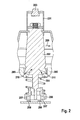
- Figure 2 illustrates a "joystick” type connection mechanism for a robotic lawn mower, with a collision detection mechanism according to the invention.
- the outer shell is connected to the main body by means of a "joystick” 201, which has a connector 202, which is flexibly connected to the outer shell, a main pillar 203, which is inserted through an aperture 204 in a section the main body 205, and a sensor element containing section 206.
- the sensor element containing section 206 contains the magnet 207, although in an alternative embodiment, this section may contain the Hall sensors.
- Hall sensors 208 are located below the sensor element containing section 206. This arrangement means that no electrical wiring is required to the outer shell or the joystick.
- the magnet or magnets are located here.
- Figure 3 is a diagrammatic view of the motion of the magnet 207 and axis 301 of the pillar of the joystick.
- the locus of all the points through which magnet 207 travels forms substantially a spherical segment contained within boundary 302, which is defined to extend over the Hall Effect sensors.
- the Hall effect sensors are located such that they are spaced from this spherical segment.
- the Hall effect sensors are thus arranged such that they do not obstruct the movement of the magnet.
- the spherical segment will be defined by the movement of the sensors and the magnet will be spaced from the spherical segment.
- the location of the magnets outside of the spherical segment of movement of the magnets gives an advantage over the prior art in that it allows for a greater range of motion for a given size of device and allows a greater range of voltage for detection as the Hall sensors may move across the whole of a magnet from one pole to the other and hence across the maximum range of magnetic field difference.
- Figure 4 shows an annular magnet 401 as used in an embodiment of the invention.
- the north pole 402 of the annular magnet is located on the inner side of annulus and the south pole 403 on the outer edge.
- Figure 5 shows an alternative to this arrangement in which there is provided an annular magnet 501 with multiple south poles 502 and multiple north poles 503 arranged circumferentially around the ring.
- the person skilled in the art will also appreciate that an arrangement of suitable bar magnets or electromagnets would perform the same task and hence the invention is not limited to any one arrangement or type of magnet.
- the preferred embodiment is that of Figure 4 , as this gives the simplest detection arrangements.
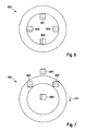
- Figure 6 shows a plan view of an arrangement of a ring magnet 401 and Hall effect sensors 601, 602, 603, 604 according to the invention.
- the Hall effect sensors may be located above or below the magnet and may move relative to the magnet if the outer shell moves relative to the main section of the robotic apparatus.
- four Hall effect sensors are used, but the person skilled in the art will appreciate that directional detection could be achieved with fewer Hall effect sensors.
- Three Hall Effect sensors could be used in combination with an annular magnet such as that illustrated in Figure 4 .
- Directional detection with just two Hall Effect sensors is possible with an appropriate arrangement of magnets. Clearly more than four Hall sensors is also possible.
- Figure 6 shows the arrangement with no contact against the shell of the robotic apparatus, with the sensors consequently located in their default positions.
- Figure 7 illustrates the effect of a collision and the movement in direction 701 of the magnet relative to the Hall effect sensors 601, 602, 603, 604.
- Figure 8 shows a side view of the arrangement in Figure 6 , illustrating the location of the sensors beneath the permanent annular magnet when the joystick is in its central position.
- Figure 9 shows a side view of the effect of the movement illustrated in Figure 7 . The position of the outer shell of the apparatus relative to the main body is detected by the relative readings of the sensors.
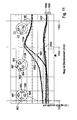
- Figure 8 shows the arrangement of sensors and the sensor outputs when a collision causes a movement of the outer shell in the direction 1000.
- Four voltage plots are shown 1001, 1002, 1003, 1004, which correspond to Hall Effect sensors 601, 602, 603, 604.
- Three positions of the magnet 401 are shown 1005, 1006, 1007, which correspond to different distances moved by the outer shell of the robotic apparatus.
- Three positions on the plots, 1008, 1009 and 1010 correspond to magnet positions 1005, 1006, 1007.
- the sensors are located in their default position, i.e. where no contact is made against any part of the outer shell.
- the sensors are located radially symmetrically around the annular magnet, positioned just inside the annulus.
- the proximity of the north pole of the magnet induces a negative Hall voltage 1011 across the sensors.
- the radial symmetry ensures that the readings from each of the sensors is substantially the same.
- a second position 1006 is shown. Here contact has been made against the outer shell of the robotic apparatus and the shell has consequently been moved in direction 1000. To simplify the explanation of the process, movement will be described in terms of the Hall sensors' movement relative to the magnet.
- Hall sensor 601 moves across the magnetic ring, such that the polarity of the magnetic field it "sees” is reversed. As a consequence, as the movement takes place, its Hall voltage initially goes to zero 1012 and then increases to a positive value 1013 as the sensor moves to the other side of the magnetic ring 401. Small reductions in the magnitudes of the voltages 1014 in the other sensors occur as they move away from the positions of peak magnetic field, which occur just inside and just outside of the magnetic ring. The position of sensor 601 is at its maximum positive voltage 1015, as it is positioned just outside of the annulus. As Hall effect sensor 601 travels further, its positive Hall voltage decreases again, as shown in position 1007. At position 1007, the sensors have moved further from their central positions.
- Hall sensors 602, 603 are positioned substantially over the edge of the outer rim of the annulus at maximum magnetic field strength from the south pole of the magnet, thus producing their highest positive Hall voltage. Sensor 601 has reached a point where the magnetic field is much reduced and hence its Hall voltage is substantially zero 1016.
- Figure 11 illustrates the effect of a movement of the magnet in a direction where the vector of the motion is in between two Hall sensors.
- the direction of the movement of the magnet is 1100.
- Three positions of this motion are shown, 1101, 1102 and 1103.
- Position 1101 is before any collision has occurred, with the Hall sensors in their default positions relative to the magnet and hence the Hall voltage readings are the same as in position 1005 in Figure 10 .
- the magnet In position 1102, the magnet has moved such that sensors 601 and 602 have both crossed over to the other side of annular magnet 401. The consequence of this is that the Hall voltages or both of these sensors changes in the same way as that of 601 changed in moving from position 1005 to 1006 in Figure 10 , i.e. to a maximum positive value 1104.
- a preloaded spring arrangement is provided that provides a self-centering mechanism for the magnet and a damping mechanism against vibration.
- a self-centering mechanism according to an embodiment of the invention is shown in Figure 12 , in which seat section 212 of joystick 201 is located in a socket 1201, and a preloaded spring 1202 is provided to damp movement of joystick 201 and to centre it after an external force has been applied to the outer shell of the robotic device.
- the seat arrangement and the preloading of the springs limit movement of the joystick unless a force greater than a required threshold is applied to the exterior of the robotic apparatus. This helps prevent noise in the Hall effect sensor readings caused by the vibrations of the robotic apparatus motor, by the apparatus moving over rough ground etc.
- the springs also provide a self-centering mechanism to overcome such problems as the distortion, deformation or deterioration of the mountings, typically made of rubber, of the outer shell.
- the threshold force may be varied by modifying the preload on the springs and the degree of damping and the strength of the self-centering mechanism can be modified by changing the stiffness of the spring. Both of these effects are illustrated in Figure 13 .
- Figure 14 is a cut-away view of the interior of the robotic device, showing outer shell 101, joystick 201, seat arrangement 212, ring magnet 401 and Hall effect sensor PCB 1401.
- Figure 15 is a cross-section of the device, showing a different view of the same components.
Priority Applications (1)
| Application Number | Priority Date | Filing Date | Title |
|---|---|---|---|
| EP12179143.8A EP2692220B1 (de) | 2012-08-03 | 2012-08-03 | Richtungsblockierungssensor |
Applications Claiming Priority (1)
| Application Number | Priority Date | Filing Date | Title |
|---|---|---|---|
| EP12179143.8A EP2692220B1 (de) | 2012-08-03 | 2012-08-03 | Richtungsblockierungssensor |
Publications (2)
| Publication Number | Publication Date |
|---|---|
| EP2692220A1 true EP2692220A1 (de) | 2014-02-05 |
| EP2692220B1 EP2692220B1 (de) | 2016-04-27 |
Family
ID=47018024
Family Applications (1)
| Application Number | Title | Priority Date | Filing Date |
|---|---|---|---|
| EP12179143.8A Active EP2692220B1 (de) | 2012-08-03 | 2012-08-03 | Richtungsblockierungssensor |
Country Status (1)
| Country | Link |
|---|---|
| EP (1) | EP2692220B1 (de) |
Cited By (16)
| Publication number | Priority date | Publication date | Assignee | Title |
|---|---|---|---|---|
| WO2015115954A1 (en) * | 2014-02-03 | 2015-08-06 | Husqvarna Ab | Obstacle detection for a robotic working tool |
| WO2016150510A1 (en) * | 2015-03-26 | 2016-09-29 | Husqvarna Ab | Improved lift/collison detection |
| WO2017109879A1 (ja) * | 2015-12-24 | 2017-06-29 | 本田技研工業株式会社 | 自動走行式芝刈機 |
| EP2803255B1 (de) * | 2013-05-15 | 2017-07-05 | Viking GmbH | Selbstfahrendes Arbeitsgerät mit Hinderniserkennung |
| CN107548676A (zh) * | 2016-06-30 | 2018-01-09 | 罗伯特·博世有限公司 | 地面加工器具 |
| JP2018073187A (ja) * | 2016-10-31 | 2018-05-10 | 本田技研工業株式会社 | 自律走行車両 |
| EP3342269A1 (de) * | 2017-01-02 | 2018-07-04 | LG Electronics Inc. | Rasenmäherroboter |
| JP2018102247A (ja) * | 2016-12-27 | 2018-07-05 | 本田技研工業株式会社 | 自律走行車両 |
| WO2018174777A1 (en) * | 2017-03-23 | 2018-09-27 | Husqvarna Ab | A robotic work tool and a method for use in a robotic work tool comprising a lift and collision detection |
| WO2018174774A1 (en) * | 2017-03-23 | 2018-09-27 | Husqvarna Ab | A robotic work tool and a method for use in a robotic work tool comprising a lift/collision detection device. |
| CN109426265A (zh) * | 2017-08-30 | 2019-03-05 | 苏州宝时得电动工具有限公司 | 自移动设备 |
| EP3470311A4 (de) * | 2016-11-30 | 2019-10-16 | Honda Motor Co., Ltd. | Autonom fahrendes fahrzeug |
| JP2021052614A (ja) * | 2019-09-27 | 2021-04-08 | 株式会社やまびこ | 自動走行式のロボット作業機 |
| CN112805206A (zh) * | 2018-10-24 | 2021-05-14 | 胡斯华纳有限公司 | 具有铰接传感器的铰接式机器人作业工具 |
| WO2022076213A1 (en) * | 2020-10-05 | 2022-04-14 | Mtd Products Inc | Sensor system and a sensing method for an autonomous device |
| CN114454817A (zh) * | 2021-12-30 | 2022-05-10 | 南京苏美达智能技术有限公司 | 一种用于自行走设备的外壳位移检测结构 |
Families Citing this family (1)
| Publication number | Priority date | Publication date | Assignee | Title |
|---|---|---|---|---|
| US11695312B2 (en) | 2017-09-01 | 2023-07-04 | Milwaukee Electric Tool Corporation | Electrostatic discharge dissipation structure |
Citations (5)
| Publication number | Priority date | Publication date | Assignee | Title |
|---|---|---|---|---|
| EP0270322A2 (de) | 1986-12-05 | 1988-06-08 | The Charles Stark Draper Laboratory, Inc. | Mehrachsenverschiebungssysteme |
| WO2001006905A1 (en) * | 1999-07-24 | 2001-02-01 | The Procter & Gamble Company | Robotic system |
| WO2002071175A1 (de) * | 2001-03-07 | 2002-09-12 | Alfred Kärcher Gmbh & Co. Kg | Bodenbearbeitungsgerät, insbesondere bodenreinigungsgerät |
| DE10242257A1 (de) * | 2001-09-14 | 2003-04-24 | Vorwerk Co Interholding | Selbsttätig verfahrbares Bodenstaub-Aufsammelgerät, sowie Kombination eines derartigen Aufsammelgerätes und einer Basisstation |
| WO2003103375A1 (en) | 2002-06-07 | 2003-12-18 | Aktiebolaget Electrolux | Self-propelled device with a sensor constituted of a hall effect transducer and an adjustable operational part |
-
2012
- 2012-08-03 EP EP12179143.8A patent/EP2692220B1/de active Active
Patent Citations (5)
| Publication number | Priority date | Publication date | Assignee | Title |
|---|---|---|---|---|
| EP0270322A2 (de) | 1986-12-05 | 1988-06-08 | The Charles Stark Draper Laboratory, Inc. | Mehrachsenverschiebungssysteme |
| WO2001006905A1 (en) * | 1999-07-24 | 2001-02-01 | The Procter & Gamble Company | Robotic system |
| WO2002071175A1 (de) * | 2001-03-07 | 2002-09-12 | Alfred Kärcher Gmbh & Co. Kg | Bodenbearbeitungsgerät, insbesondere bodenreinigungsgerät |
| DE10242257A1 (de) * | 2001-09-14 | 2003-04-24 | Vorwerk Co Interholding | Selbsttätig verfahrbares Bodenstaub-Aufsammelgerät, sowie Kombination eines derartigen Aufsammelgerätes und einer Basisstation |
| WO2003103375A1 (en) | 2002-06-07 | 2003-12-18 | Aktiebolaget Electrolux | Self-propelled device with a sensor constituted of a hall effect transducer and an adjustable operational part |
Cited By (33)
| Publication number | Priority date | Publication date | Assignee | Title |
|---|---|---|---|---|
| EP2803255B1 (de) * | 2013-05-15 | 2017-07-05 | Viking GmbH | Selbstfahrendes Arbeitsgerät mit Hinderniserkennung |
| WO2015115954A1 (en) * | 2014-02-03 | 2015-08-06 | Husqvarna Ab | Obstacle detection for a robotic working tool |
| US10031527B2 (en) | 2014-02-03 | 2018-07-24 | Husqvarna Ab | Obstacle detection for a robotic working tool |
| EP3102914B1 (de) | 2014-02-03 | 2018-08-08 | Husqvarna AB | Hinderniserkennung für ein robotisches arbeitswerkzeug |
| WO2016150510A1 (en) * | 2015-03-26 | 2016-09-29 | Husqvarna Ab | Improved lift/collison detection |
| US10108198B2 (en) | 2015-03-26 | 2018-10-23 | Husqvarna Ab | Lift/collison detection |
| JPWO2017109879A1 (ja) * | 2015-12-24 | 2018-09-27 | 本田技研工業株式会社 | 自動走行式芝刈機 |
| WO2017109879A1 (ja) * | 2015-12-24 | 2017-06-29 | 本田技研工業株式会社 | 自動走行式芝刈機 |
| AU2015418271B2 (en) * | 2015-12-24 | 2019-04-04 | Honda Motor Co., Ltd. | Autonomous lawn mower |
| US10674660B2 (en) | 2015-12-24 | 2020-06-09 | Honda Motor Co., Ltd | Autonomous lawn mower with movable cover |
| EP3395148A4 (de) * | 2015-12-24 | 2019-01-02 | Honda Motor Co., Ltd. | Robotischer rasenmäher |
| CN107548676A (zh) * | 2016-06-30 | 2018-01-09 | 罗伯特·博世有限公司 | 地面加工器具 |
| JP2018073187A (ja) * | 2016-10-31 | 2018-05-10 | 本田技研工業株式会社 | 自律走行車両 |
| EP3470311A4 (de) * | 2016-11-30 | 2019-10-16 | Honda Motor Co., Ltd. | Autonom fahrendes fahrzeug |
| US11206760B2 (en) | 2016-12-27 | 2021-12-28 | Honda Motor Co., Ltd. | Utility vehicle with spring suspension between cover and chassis |
| WO2018123597A1 (ja) * | 2016-12-27 | 2018-07-05 | 本田技研工業株式会社 | 作業車両 |
| JP2018102247A (ja) * | 2016-12-27 | 2018-07-05 | 本田技研工業株式会社 | 自律走行車両 |
| CN110113933B (zh) * | 2016-12-27 | 2022-06-03 | 本田技研工业株式会社 | 作业车辆 |
| CN110113933A (zh) * | 2016-12-27 | 2019-08-09 | 本田技研工业株式会社 | 作业车辆 |
| US11096325B2 (en) | 2017-01-02 | 2021-08-24 | Lg Electronics Inc. | Lawn mower robot |
| EP3342269A1 (de) * | 2017-01-02 | 2018-07-04 | LG Electronics Inc. | Rasenmäherroboter |
| AU2018200004B2 (en) * | 2017-01-02 | 2019-09-26 | Lg Electronics Inc. | Lawn mower robot |
| EP3944748A1 (de) * | 2017-01-02 | 2022-02-02 | LG Electronics Inc. | Rasenmäherroboter |
| WO2018174774A1 (en) * | 2017-03-23 | 2018-09-27 | Husqvarna Ab | A robotic work tool and a method for use in a robotic work tool comprising a lift/collision detection device. |
| WO2018174777A1 (en) * | 2017-03-23 | 2018-09-27 | Husqvarna Ab | A robotic work tool and a method for use in a robotic work tool comprising a lift and collision detection |
| US11844303B2 (en) | 2017-03-23 | 2023-12-19 | Husqvarna Ab | Robotic work tool and a method for use in a robotic work tool comprising a lift/collision detection device |
| CN109426265A (zh) * | 2017-08-30 | 2019-03-05 | 苏州宝时得电动工具有限公司 | 自移动设备 |
| CN112805206A (zh) * | 2018-10-24 | 2021-05-14 | 胡斯华纳有限公司 | 具有铰接传感器的铰接式机器人作业工具 |
| EP3911554A4 (de) * | 2018-10-24 | 2022-11-30 | Husqvarna Ab | Gelenkiges robotisches arbeitswerkzeug mit gelenksensor |
| JP2021052614A (ja) * | 2019-09-27 | 2021-04-08 | 株式会社やまびこ | 自動走行式のロボット作業機 |
| WO2022076213A1 (en) * | 2020-10-05 | 2022-04-14 | Mtd Products Inc | Sensor system and a sensing method for an autonomous device |
| CN114454817A (zh) * | 2021-12-30 | 2022-05-10 | 南京苏美达智能技术有限公司 | 一种用于自行走设备的外壳位移检测结构 |
| CN114454817B (zh) * | 2021-12-30 | 2023-11-03 | 南京苏美达智能技术有限公司 | 一种用于自行走设备的外壳位移检测结构 |
Also Published As
| Publication number | Publication date |
|---|---|
| EP2692220B1 (de) | 2016-04-27 |
Similar Documents
| Publication | Publication Date | Title |
|---|---|---|
| EP2692220B1 (de) | Richtungsblockierungssensor | |
| US10375880B2 (en) | Robot lawn mower bumper system | |
| CN107404839B (zh) | 改进的提升/碰撞检测 | |
| EP3315000B1 (de) | Roboter mit aufgehängter hülle zur kontakterkennung | |
| EP3395148B1 (de) | Robotischer rasenmäher | |
| EP1731982A1 (de) | Trägheitsnavigationssteuerungssystem für ein fahrerloses Fahrzeug unter Verwendung von Laser-Hindernissensoren | |
| US20150185733A1 (en) | Displacement Sensor for a Robotic Vehicle Detecting a Lift Event and a Collision Event | |
| EP2621066B1 (de) | Linearer aktuator | |
| SE527093C2 (sv) | Robotstädare | |
| US11070122B2 (en) | Multi-degree-of-freedom electromagnetic machine | |
| JP2020073936A5 (ja) | 検出装置 | |
| US9976877B2 (en) | Non-contact sensor for electromagnetic actuator assembly for a locking assembly | |
| EP2594456B1 (de) | Fahrzeuglenkungssystem | |
| US9871433B2 (en) | Linear actuator and tube assembly method for linear actuator | |
| US11953074B2 (en) | Suspension for outdoor robotic tools | |
| WO2018123597A1 (ja) | 作業車両 | |
| WO2015175847A1 (en) | Positional sensor for locking gearset | |
| EP3316067B1 (de) | Kontaktgeber für roboter | |
| JP5305082B2 (ja) | 自律移動装置 | |
| JP5517422B2 (ja) | 自律移動装置 | |
| WO2020145911A1 (en) | Joystick with a precise control | |
| JP6373790B2 (ja) | 非接触スイッチ | |
| JP7251262B2 (ja) | 可動体、ロボットおよび移動体 | |
| CN219039714U (zh) | 摇摆位置检测装置及输入设备 | |
| US20220107653A1 (en) | Sensor system and sensing method for an autonomous device |
Legal Events
| Date | Code | Title | Description |
|---|---|---|---|
| AK | Designated contracting states |
Kind code of ref document: A1 Designated state(s): AL AT BE BG CH CY CZ DE DK EE ES FI FR GB GR HR HU IE IS IT LI LT LU LV MC MK MT NL NO PL PT RO RS SE SI SK SM TR |
|
| AX | Request for extension of the european patent |
Extension state: BA ME |
|
| PUAI | Public reference made under article 153(3) epc to a published international application that has entered the european phase |
Free format text: ORIGINAL CODE: 0009012 |
|
| 17P | Request for examination filed |
Effective date: 20140805 |
|
| RBV | Designated contracting states (corrected) |
Designated state(s): AL AT BE BG CH CY CZ DE DK EE ES FI FR GB GR HR HU IE IS IT LI LT LU LV MC MK MT NL NO PL PT RO RS SE SI SK SM TR |
|
| GRAP | Despatch of communication of intention to grant a patent |
Free format text: ORIGINAL CODE: EPIDOSNIGR1 |
|
| RIC1 | Information provided on ipc code assigned before grant |
Ipc: A47L 9/28 20060101ALI20151021BHEP Ipc: A47L 9/00 20060101ALI20151021BHEP Ipc: A01D 34/00 20060101AFI20151021BHEP Ipc: B60L 15/20 20060101ALI20151021BHEP Ipc: B60L 11/18 20060101ALI20151021BHEP Ipc: B60L 1/00 20060101ALI20151021BHEP Ipc: B60L 3/00 20060101ALI20151021BHEP Ipc: G01D 5/14 20060101ALI20151021BHEP |
|
| INTG | Intention to grant announced |
Effective date: 20151110 |
|
| RIN1 | Information on inventor provided before grant (corrected) |
Inventor name: COUSSINS, ADRIAN Inventor name: JOHNSON, WILLIAM A. |
|
| GRAS | Grant fee paid |
Free format text: ORIGINAL CODE: EPIDOSNIGR3 |
|
| GRAA | (expected) grant |
Free format text: ORIGINAL CODE: 0009210 |
|
| AK | Designated contracting states |
Kind code of ref document: B1 Designated state(s): AL AT BE BG CH CY CZ DE DK EE ES FI FR GB GR HR HU IE IS IT LI LT LU LV MC MK MT NL NO PL PT RO RS SE SI SK SM TR |
|
| REG | Reference to a national code |
Ref country code: GB Ref legal event code: FG4D |
|
| REG | Reference to a national code |
Ref country code: CH Ref legal event code: EP |
|
| REG | Reference to a national code |
Ref country code: AT Ref legal event code: REF Ref document number: 793673 Country of ref document: AT Kind code of ref document: T Effective date: 20160515 |
|
| REG | Reference to a national code |
Ref country code: IE Ref legal event code: FG4D |
|
| REG | Reference to a national code |
Ref country code: DE Ref legal event code: R096 Ref document number: 602012017569 Country of ref document: DE |
|
| REG | Reference to a national code |
Ref country code: LT Ref legal event code: MG4D |
|
| REG | Reference to a national code |
Ref country code: NL Ref legal event code: MP Effective date: 20160427 |
|
| REG | Reference to a national code |
Ref country code: AT Ref legal event code: MK05 Ref document number: 793673 Country of ref document: AT Kind code of ref document: T Effective date: 20160427 |
|
| PG25 | Lapsed in a contracting state [announced via postgrant information from national office to epo] |
Ref country code: NL Free format text: LAPSE BECAUSE OF FAILURE TO SUBMIT A TRANSLATION OF THE DESCRIPTION OR TO PAY THE FEE WITHIN THE PRESCRIBED TIME-LIMIT Effective date: 20160427 |
|
| PG25 | Lapsed in a contracting state [announced via postgrant information from national office to epo] |
Ref country code: LT Free format text: LAPSE BECAUSE OF FAILURE TO SUBMIT A TRANSLATION OF THE DESCRIPTION OR TO PAY THE FEE WITHIN THE PRESCRIBED TIME-LIMIT Effective date: 20160427 Ref country code: PL Free format text: LAPSE BECAUSE OF FAILURE TO SUBMIT A TRANSLATION OF THE DESCRIPTION OR TO PAY THE FEE WITHIN THE PRESCRIBED TIME-LIMIT Effective date: 20160427 Ref country code: NO Free format text: LAPSE BECAUSE OF FAILURE TO SUBMIT A TRANSLATION OF THE DESCRIPTION OR TO PAY THE FEE WITHIN THE PRESCRIBED TIME-LIMIT Effective date: 20160727 Ref country code: FI Free format text: LAPSE BECAUSE OF FAILURE TO SUBMIT A TRANSLATION OF THE DESCRIPTION OR TO PAY THE FEE WITHIN THE PRESCRIBED TIME-LIMIT Effective date: 20160427 |
|
| PG25 | Lapsed in a contracting state [announced via postgrant information from national office to epo] |
Ref country code: HR Free format text: LAPSE BECAUSE OF FAILURE TO SUBMIT A TRANSLATION OF THE DESCRIPTION OR TO PAY THE FEE WITHIN THE PRESCRIBED TIME-LIMIT Effective date: 20160427 Ref country code: ES Free format text: LAPSE BECAUSE OF FAILURE TO SUBMIT A TRANSLATION OF THE DESCRIPTION OR TO PAY THE FEE WITHIN THE PRESCRIBED TIME-LIMIT Effective date: 20160427 Ref country code: PT Free format text: LAPSE BECAUSE OF FAILURE TO SUBMIT A TRANSLATION OF THE DESCRIPTION OR TO PAY THE FEE WITHIN THE PRESCRIBED TIME-LIMIT Effective date: 20160829 Ref country code: LV Free format text: LAPSE BECAUSE OF FAILURE TO SUBMIT A TRANSLATION OF THE DESCRIPTION OR TO PAY THE FEE WITHIN THE PRESCRIBED TIME-LIMIT Effective date: 20160427 Ref country code: SE Free format text: LAPSE BECAUSE OF FAILURE TO SUBMIT A TRANSLATION OF THE DESCRIPTION OR TO PAY THE FEE WITHIN THE PRESCRIBED TIME-LIMIT Effective date: 20160427 Ref country code: AT Free format text: LAPSE BECAUSE OF FAILURE TO SUBMIT A TRANSLATION OF THE DESCRIPTION OR TO PAY THE FEE WITHIN THE PRESCRIBED TIME-LIMIT Effective date: 20160427 Ref country code: RS Free format text: LAPSE BECAUSE OF FAILURE TO SUBMIT A TRANSLATION OF THE DESCRIPTION OR TO PAY THE FEE WITHIN THE PRESCRIBED TIME-LIMIT Effective date: 20160427 Ref country code: GR Free format text: LAPSE BECAUSE OF FAILURE TO SUBMIT A TRANSLATION OF THE DESCRIPTION OR TO PAY THE FEE WITHIN THE PRESCRIBED TIME-LIMIT Effective date: 20160728 |
|
| PG25 | Lapsed in a contracting state [announced via postgrant information from national office to epo] |
Ref country code: IT Free format text: LAPSE BECAUSE OF FAILURE TO SUBMIT A TRANSLATION OF THE DESCRIPTION OR TO PAY THE FEE WITHIN THE PRESCRIBED TIME-LIMIT Effective date: 20160427 Ref country code: BE Free format text: LAPSE BECAUSE OF FAILURE TO SUBMIT A TRANSLATION OF THE DESCRIPTION OR TO PAY THE FEE WITHIN THE PRESCRIBED TIME-LIMIT Effective date: 20160427 |
|
| REG | Reference to a national code |
Ref country code: DE Ref legal event code: R097 Ref document number: 602012017569 Country of ref document: DE |
|
| PG25 | Lapsed in a contracting state [announced via postgrant information from national office to epo] |
Ref country code: CZ Free format text: LAPSE BECAUSE OF FAILURE TO SUBMIT A TRANSLATION OF THE DESCRIPTION OR TO PAY THE FEE WITHIN THE PRESCRIBED TIME-LIMIT Effective date: 20160427 Ref country code: RO Free format text: LAPSE BECAUSE OF FAILURE TO SUBMIT A TRANSLATION OF THE DESCRIPTION OR TO PAY THE FEE WITHIN THE PRESCRIBED TIME-LIMIT Effective date: 20160427 Ref country code: EE Free format text: LAPSE BECAUSE OF FAILURE TO SUBMIT A TRANSLATION OF THE DESCRIPTION OR TO PAY THE FEE WITHIN THE PRESCRIBED TIME-LIMIT Effective date: 20160427 Ref country code: DK Free format text: LAPSE BECAUSE OF FAILURE TO SUBMIT A TRANSLATION OF THE DESCRIPTION OR TO PAY THE FEE WITHIN THE PRESCRIBED TIME-LIMIT Effective date: 20160427 Ref country code: SK Free format text: LAPSE BECAUSE OF FAILURE TO SUBMIT A TRANSLATION OF THE DESCRIPTION OR TO PAY THE FEE WITHIN THE PRESCRIBED TIME-LIMIT Effective date: 20160427 |
|
| PG25 | Lapsed in a contracting state [announced via postgrant information from national office to epo] |
Ref country code: SM Free format text: LAPSE BECAUSE OF FAILURE TO SUBMIT A TRANSLATION OF THE DESCRIPTION OR TO PAY THE FEE WITHIN THE PRESCRIBED TIME-LIMIT Effective date: 20160427 |
|
| PLBE | No opposition filed within time limit |
Free format text: ORIGINAL CODE: 0009261 |
|
| STAA | Information on the status of an ep patent application or granted ep patent |
Free format text: STATUS: NO OPPOSITION FILED WITHIN TIME LIMIT |
|
| PG25 | Lapsed in a contracting state [announced via postgrant information from national office to epo] |
Ref country code: MC Free format text: LAPSE BECAUSE OF FAILURE TO SUBMIT A TRANSLATION OF THE DESCRIPTION OR TO PAY THE FEE WITHIN THE PRESCRIBED TIME-LIMIT Effective date: 20160427 |
|
| REG | Reference to a national code |
Ref country code: CH Ref legal event code: PL |
|
| 26N | No opposition filed |
Effective date: 20170130 |
|
| GBPC | Gb: european patent ceased through non-payment of renewal fee |
Effective date: 20160803 |
|
| PG25 | Lapsed in a contracting state [announced via postgrant information from national office to epo] |
Ref country code: LI Free format text: LAPSE BECAUSE OF NON-PAYMENT OF DUE FEES Effective date: 20160831 Ref country code: CH Free format text: LAPSE BECAUSE OF NON-PAYMENT OF DUE FEES Effective date: 20160831 |
|
| REG | Reference to a national code |
Ref country code: FR Ref legal event code: ST Effective date: 20170428 |
|
| PG25 | Lapsed in a contracting state [announced via postgrant information from national office to epo] |
Ref country code: SI Free format text: LAPSE BECAUSE OF FAILURE TO SUBMIT A TRANSLATION OF THE DESCRIPTION OR TO PAY THE FEE WITHIN THE PRESCRIBED TIME-LIMIT Effective date: 20160427 |
|
| REG | Reference to a national code |
Ref country code: IE Ref legal event code: MM4A |
|
| PG25 | Lapsed in a contracting state [announced via postgrant information from national office to epo] |
Ref country code: IE Free format text: LAPSE BECAUSE OF NON-PAYMENT OF DUE FEES Effective date: 20160803 Ref country code: FR Free format text: LAPSE BECAUSE OF NON-PAYMENT OF DUE FEES Effective date: 20160831 Ref country code: GB Free format text: LAPSE BECAUSE OF NON-PAYMENT OF DUE FEES Effective date: 20160803 |
|
| PG25 | Lapsed in a contracting state [announced via postgrant information from national office to epo] |
Ref country code: LU Free format text: LAPSE BECAUSE OF NON-PAYMENT OF DUE FEES Effective date: 20160803 |
|
| PG25 | Lapsed in a contracting state [announced via postgrant information from national office to epo] |
Ref country code: HU Free format text: LAPSE BECAUSE OF FAILURE TO SUBMIT A TRANSLATION OF THE DESCRIPTION OR TO PAY THE FEE WITHIN THE PRESCRIBED TIME-LIMIT; INVALID AB INITIO Effective date: 20120803 Ref country code: CY Free format text: LAPSE BECAUSE OF FAILURE TO SUBMIT A TRANSLATION OF THE DESCRIPTION OR TO PAY THE FEE WITHIN THE PRESCRIBED TIME-LIMIT Effective date: 20160427 |
|
| PG25 | Lapsed in a contracting state [announced via postgrant information from national office to epo] |
Ref country code: IS Free format text: LAPSE BECAUSE OF FAILURE TO SUBMIT A TRANSLATION OF THE DESCRIPTION OR TO PAY THE FEE WITHIN THE PRESCRIBED TIME-LIMIT Effective date: 20160427 Ref country code: MK Free format text: LAPSE BECAUSE OF FAILURE TO SUBMIT A TRANSLATION OF THE DESCRIPTION OR TO PAY THE FEE WITHIN THE PRESCRIBED TIME-LIMIT Effective date: 20160427 Ref country code: TR Free format text: LAPSE BECAUSE OF FAILURE TO SUBMIT A TRANSLATION OF THE DESCRIPTION OR TO PAY THE FEE WITHIN THE PRESCRIBED TIME-LIMIT Effective date: 20160427 Ref country code: MT Free format text: LAPSE BECAUSE OF NON-PAYMENT OF DUE FEES Effective date: 20160831 |
|
| PG25 | Lapsed in a contracting state [announced via postgrant information from national office to epo] |
Ref country code: BG Free format text: LAPSE BECAUSE OF FAILURE TO SUBMIT A TRANSLATION OF THE DESCRIPTION OR TO PAY THE FEE WITHIN THE PRESCRIBED TIME-LIMIT Effective date: 20160427 |
|
| PG25 | Lapsed in a contracting state [announced via postgrant information from national office to epo] |
Ref country code: AL Free format text: LAPSE BECAUSE OF FAILURE TO SUBMIT A TRANSLATION OF THE DESCRIPTION OR TO PAY THE FEE WITHIN THE PRESCRIBED TIME-LIMIT Effective date: 20160427 |
|
| PGFP | Annual fee paid to national office [announced via postgrant information from national office to epo] |
Ref country code: DE Payment date: 20231025 Year of fee payment: 12 |
|
| REG | Reference to a national code |
Ref country code: DE Ref legal event code: R084 Ref document number: 602012017569 Country of ref document: DE |