EP2691590B1 - Tür oder fenster eines gebäudes mit einer motorischen antriebsvorrichtung - Google Patents
Tür oder fenster eines gebäudes mit einer motorischen antriebsvorrichtung Download PDFInfo
- Publication number
- EP2691590B1 EP2691590B1 EP12716269.1A EP12716269A EP2691590B1 EP 2691590 B1 EP2691590 B1 EP 2691590B1 EP 12716269 A EP12716269 A EP 12716269A EP 2691590 B1 EP2691590 B1 EP 2691590B1
- Authority
- EP
- European Patent Office
- Prior art keywords
- spindle
- frame
- push rod
- door
- swivel element
- Prior art date
- Legal status (The legal status is an assumption and is not a legal conclusion. Google has not performed a legal analysis and makes no representation as to the accuracy of the status listed.)
- Active
Links
Images





Classifications
-
- E—FIXED CONSTRUCTIONS
- E05—LOCKS; KEYS; WINDOW OR DOOR FITTINGS; SAFES
- E05F—DEVICES FOR MOVING WINGS INTO OPEN OR CLOSED POSITION; CHECKS FOR WINGS; WING FITTINGS NOT OTHERWISE PROVIDED FOR, CONCERNED WITH THE FUNCTIONING OF THE WING
- E05F1/00—Closers or openers for wings, not otherwise provided for in this subclass
- E05F1/08—Closers or openers for wings, not otherwise provided for in this subclass spring-actuated, e.g. for horizontally sliding wings
- E05F1/10—Closers or openers for wings, not otherwise provided for in this subclass spring-actuated, e.g. for horizontally sliding wings for swinging wings, e.g. counterbalance
- E05F1/1041—Closers or openers for wings, not otherwise provided for in this subclass spring-actuated, e.g. for horizontally sliding wings for swinging wings, e.g. counterbalance with a coil spring perpendicular to the pivot axis
- E05F1/105—Closers or openers for wings, not otherwise provided for in this subclass spring-actuated, e.g. for horizontally sliding wings for swinging wings, e.g. counterbalance with a coil spring perpendicular to the pivot axis with a compression spring
-
- E—FIXED CONSTRUCTIONS
- E05—LOCKS; KEYS; WINDOW OR DOOR FITTINGS; SAFES
- E05F—DEVICES FOR MOVING WINGS INTO OPEN OR CLOSED POSITION; CHECKS FOR WINGS; WING FITTINGS NOT OTHERWISE PROVIDED FOR, CONCERNED WITH THE FUNCTIONING OF THE WING
- E05F15/00—Power-operated mechanisms for wings
- E05F15/60—Power-operated mechanisms for wings using electrical actuators
- E05F15/603—Power-operated mechanisms for wings using electrical actuators using rotary electromotors
- E05F15/611—Power-operated mechanisms for wings using electrical actuators using rotary electromotors for swinging wings
- E05F15/616—Power-operated mechanisms for wings using electrical actuators using rotary electromotors for swinging wings operated by push-pull mechanisms
- E05F15/622—Power-operated mechanisms for wings using electrical actuators using rotary electromotors for swinging wings operated by push-pull mechanisms using screw-and-nut mechanisms
-
- E—FIXED CONSTRUCTIONS
- E05—LOCKS; KEYS; WINDOW OR DOOR FITTINGS; SAFES
- E05Y—INDEXING SCHEME ASSOCIATED WITH SUBCLASSES E05D AND E05F, RELATING TO CONSTRUCTION ELEMENTS, ELECTRIC CONTROL, POWER SUPPLY, POWER SIGNAL OR TRANSMISSION, USER INTERFACES, MOUNTING OR COUPLING, DETAILS, ACCESSORIES, AUXILIARY OPERATIONS NOT OTHERWISE PROVIDED FOR, APPLICATION THEREOF
- E05Y2201/00—Constructional elements; Accessories therefor
- E05Y2201/60—Suspension or transmission members; Accessories therefor
- E05Y2201/622—Suspension or transmission members elements
- E05Y2201/624—Arms
-
- E—FIXED CONSTRUCTIONS
- E05—LOCKS; KEYS; WINDOW OR DOOR FITTINGS; SAFES
- E05Y—INDEXING SCHEME ASSOCIATED WITH SUBCLASSES E05D AND E05F, RELATING TO CONSTRUCTION ELEMENTS, ELECTRIC CONTROL, POWER SUPPLY, POWER SIGNAL OR TRANSMISSION, USER INTERFACES, MOUNTING OR COUPLING, DETAILS, ACCESSORIES, AUXILIARY OPERATIONS NOT OTHERWISE PROVIDED FOR, APPLICATION THEREOF
- E05Y2600/00—Mounting or coupling arrangements for elements provided for in this subclass
- E05Y2600/40—Mounting location; Visibility of the elements
- E05Y2600/41—Concealed
-
- E—FIXED CONSTRUCTIONS
- E05—LOCKS; KEYS; WINDOW OR DOOR FITTINGS; SAFES
- E05Y—INDEXING SCHEME ASSOCIATED WITH SUBCLASSES E05D AND E05F, RELATING TO CONSTRUCTION ELEMENTS, ELECTRIC CONTROL, POWER SUPPLY, POWER SIGNAL OR TRANSMISSION, USER INTERFACES, MOUNTING OR COUPLING, DETAILS, ACCESSORIES, AUXILIARY OPERATIONS NOT OTHERWISE PROVIDED FOR, APPLICATION THEREOF
- E05Y2600/00—Mounting or coupling arrangements for elements provided for in this subclass
- E05Y2600/40—Mounting location; Visibility of the elements
- E05Y2600/45—Mounting location; Visibility of the elements in or on the fixed frame
-
- E—FIXED CONSTRUCTIONS
- E05—LOCKS; KEYS; WINDOW OR DOOR FITTINGS; SAFES
- E05Y—INDEXING SCHEME ASSOCIATED WITH SUBCLASSES E05D AND E05F, RELATING TO CONSTRUCTION ELEMENTS, ELECTRIC CONTROL, POWER SUPPLY, POWER SIGNAL OR TRANSMISSION, USER INTERFACES, MOUNTING OR COUPLING, DETAILS, ACCESSORIES, AUXILIARY OPERATIONS NOT OTHERWISE PROVIDED FOR, APPLICATION THEREOF
- E05Y2900/00—Application of doors, windows, wings or fittings thereof
- E05Y2900/10—Application of doors, windows, wings or fittings thereof for buildings or parts thereof
- E05Y2900/13—Type of wing
- E05Y2900/132—Doors
-
- E—FIXED CONSTRUCTIONS
- E05—LOCKS; KEYS; WINDOW OR DOOR FITTINGS; SAFES
- E05Y—INDEXING SCHEME ASSOCIATED WITH SUBCLASSES E05D AND E05F, RELATING TO CONSTRUCTION ELEMENTS, ELECTRIC CONTROL, POWER SUPPLY, POWER SIGNAL OR TRANSMISSION, USER INTERFACES, MOUNTING OR COUPLING, DETAILS, ACCESSORIES, AUXILIARY OPERATIONS NOT OTHERWISE PROVIDED FOR, APPLICATION THEREOF
- E05Y2900/00—Application of doors, windows, wings or fittings thereof
- E05Y2900/10—Application of doors, windows, wings or fittings thereof for buildings or parts thereof
- E05Y2900/13—Type of wing
- E05Y2900/148—Windows
Definitions
- the invention relates to an assembly of a door or a window of a building.
- Such an assembly has a pivoting element, a frame on which the pivoting element is pivotably arranged about a pivot axis, and a motor drive device which acts between the pivoting element and the frame to pivot the pivoting element relative to the frame.
- the motor drive device is formed by a spindle drive with a spindle extending along a longitudinal axis and a spindle nut that is in threaded engagement with the spindle.
- the pivoting element is a door or a window of a building, for example a front door, an inner door or a building window.
- the drive device is used for motorized adjustment of the door or the window, wherein the drive device can have an electric motor, for example, which sets the spindle and the spindle nut of the spindle drive in a relative rotational movement to pivot the pivoting element, so that the spindle nut rolls on and along the spindle of the spindle so as to transmit torque for pivoting the door or window relative to the frame.
- the frame can accordingly be a door frame or a window frame.
- the pivoting element is usually used to close an opening delimited by the frame.
- the pivoting element has a so-called secondary closing edge, via which the pivoting element is arranged on the frame so that it can pivot about the pivot axis, and a main closing edge that runs parallel to the secondary closing edge and is remote from the pivot axis.
- the secondary closing edge and the main closing edge are each assigned a counter-closing edge of the frame, which is just opposite the secondary closing edge or the main closing edge when the pivoting element is in a closed position. (It should be noted that the edges extending transversely to the main closing edge, e.g. at the top and called “secondary closing edges" at the bottom of a door leaf.
- the spindle drive is arranged in a fixed position on the pivoting element along the longitudinal axis along which the spindle extends. This means that the spindle drive is arranged on the pivoting element in such a way that the position of the longitudinal axis on the pivoting element is fixed.
- the spindle drive with the spindle extending along the longitudinal axis is thus not pivoted relative to the pivoting element during a pivoting movement of the pivoting element relative to the frame, but remains in a fixed position relative to the component on which it is arranged.
- a drive device in the form of a spindle drive, in which a spindle is rotated to adjust the sash, so that a spindle nut that is in threaded engagement with the spindle rolls on the spindle and along a longitudinal axis, along which the spindle is extended on a frame, is moved.
- the spindle nut is coupled to the wing via a lever and moves the wing along the spindle as it moves.
- a disadvantage in driving the DE 102 13 427 A1 is that pivoting a wing relative to a frame is only possible by a comparatively small angle.
- a lever is also required, protruding from the frame and coupled to the sash. This lever is clearly visible from the outside and also prevents access when the sash is open.
- a revolving door drive with an electronic controller in which a drive device is provided in the form of a spindle drive with a rotatable spindle and a spindle nut arranged on the spindle.
- the spindle nut moves a toothed rack, which is in engagement with a drive axle in such a way that when the toothed rack moves, the drive axle is set into a rotary movement, via which a door leaf can be pivoted.
- Conventional drive devices for pivoting a pivoting element in the form of a door or a window of a building are designed as an attachment to a pivoting element or a frame or at least use visible levers which protrude from the pivoting element and protrude from a plane in which the pivoting element extends.
- the DE 101 17 933 A1 discloses an automatically operable vehicle door (particularly a tailgate) in which an adjusting drive with a spindle drive is provided.
- the spindle drive has a rotatable spindle and a nut engaged with the spindle.
- the spindle nut is coupled to a hinge bracket via a connecting rod, so that the tailgate can be pivoted by adjusting the spindle nut lengthways.
- the US 7,219,391 B1 discloses a door closer which is arranged within a door leaf and which has a push element which is supported via a link rod on a hinge side of a door frame.
- one from the EP 2 196 702 A2 known spindle drive is to be coupled on both sides via fastening elements with the components that can be pivoted relative to one another.
- the object of the present invention is to provide an assembly of a door or a window of a building which, with a simple design and reliable power transmission, makes it possible to dispense with clearly visible levers protruding from the plane of a pivoting element.
- the spindle drive has a push rod that extends along the longitudinal axis, which, driven by a relative movement of the spindle to the spindle nut, can be displaced on the pivoting element along the longitudinal axis and is coupled to the frame via a joint rod that is articulated to the push rod, so that, by moving the Push rod to pivot the pivoting element relative to the frame.
- the present invention is based on the idea of using a spindle drive with a spindle that extends along a longitudinal axis to drive a push rod that also extends along the longitudinal axis for pivoting the pivoting element.
- the push rod is moved along the longitudinal axis to swivel the swivel element and is coupled to the frame via a link rod.
- the push rod is moved exclusively along the longitudinal axis and transmits the torque for pivoting the pivoting element via the coupling of the joint rod, the movement of the push rod can take place in the plane of the pivoting element without a lever for power transmission from the pivoting element or the frame being visible to the outside presides.
- the drive device in the form of the spindle drive is arranged on the pivoting element.
- the spindle drive is arranged inside a body of the pivoting element, for example inside a door leaf.
- the longitudinal axis, along which the push rod extends, is advantageously directed perpendicularly to the pivot axis about which the pivot element is pivotably arranged on the frame.
- the longitudinal axis and thus the spindle of the spindle drive and the connecting rod thus extend perpendicularly to the pivot axis, the spindle drive being pivoted in a fixed position with the pivot element when the pivot element is pivoted.
- the push rod acts between the pivoting element and the frame via a secondary closing edge of the pivoting element, via which the pivoting element is pivotably arranged on the frame and which is directed parallel to the pivoting axis.
- the torque for pivoting the pivoting element is thus generated in the area of the secondary closing edge—that is, on the edge of the pivoting element via which the pivoting element is arranged pivotably on the frame. Because the push rod acts via the secondary closing edge, the free extension path over which the push rod and/or the articulated rod extend freely and visibly between the pivoting element and the frame is short because in the area of the secondary closing edge the distance between the pivoting element and the frame is small.
- the articulated rod emerges from the pivoting element at the secondary closing edge, and the push rod is supported in an articulated manner via the articulated rod on a counter-closing edge of the frame opposite the secondary closing edge.
- the connecting rod thus forms, together with the articulated rod, a lever mechanism between the secondary closing edge of the pivoting element and the associated counter-closing edge of the frame, which is designed in such a way that during a displacement movement of the connecting rod along the longitudinal axis directed perpendicularly to the pivoting axis in the plane of the pivoting element, a torque is generated between the pivoting element and causing the frame to pivot the pivot member relative to the frame.
- the pivoting element pushes itself off the frame, so to speak, via the connecting rod and the connecting rod and is pivoted due to the displacement movement of the connecting rod.
- the articulated rod is articulated both to the counter-closing edge of the frame and to the push rod, with a suitable, possibly detachable coupling point being provided on the push rod for articulated connection to the articulated rod, and on the counter-closing edge a suitable bearing for the articulated arrangement of the articulated rod.
- the pivoting element can be pivoted relative to the frame in an electric motor-driven manner.
- the motorized drive device can be designed in such a way that it holds the pivoting element, for example the door or window of a building, in a closed position in which the opening delimited by the frame is closed by the pivoting element.
- a separate locking device for example a door lock, could thus be dispensed with.
- the spindle drive it is possible to design the spindle drive to be self-locking or non-self-locking. If the spindle drive is designed to be self-locking, the pivoting element can only be adjusted by an electric motor, driven by the motor drive device, while manual adjustment by pushing or pulling the pivoting element is prevented by the self-locking spindle drive. However, if the spindle drive is not designed to be self-locking, opening is possible by manually moving the pivoting element, for example the door or window, when applying sufficient force, so that a door or window can be opened in an emergency, for example.
- the push rod can be coupled to a locking linkage for locking or unlocking the pivoting element relative to the frame depending on the position of the push rod.
- This is based on the idea of using the drive device not only for pivoting the pivoting element, but also for (mechanically) controlling a locking of the pivoting element.
- the locking mechanism is then actuated via the locking linkage in such a way that the locking is released and the pivoting element is unlocked.
- locking is established when the push rod is moved to close the pivoting element and the pivoting element reaches its closed position. In this way, a secure locking and thus a secure hold of the pivoting element in its closed position on the frame are ensured.
- spindle drives within the scope of the claims are conceivable and can be used for the drive device of the type mentioned here.
- the spindle is rotatably arranged on a housing of the spindle drive and is operatively connected to an electric motor for driving the spindle.
- the spindle nut is non-rotatably arranged on a tube of the connecting rod that is displaceably mounted on the housing in such a way that when the spindle rotates, the spindle nut is displaced together with the tube along the longitudinal axis relative to the housing.
- the spindle nut By rotating the spindle, driven by the electric motor, the spindle nut (which is arranged on the tube of the push rod in a rotationally fixed manner) rolls off the spindle, so that due to the threaded engagement of the spindle nut with the spindle, the spindle nut moves along the longitudinal axis along which the Spindle extends, is adjusted relative to the spindle and thus the push rod is moved relative to the spindle.
- the electric motor can be arranged coaxially to the spindle in the housing, resulting in a slim design of the spindle drive that extends longitudinally along the longitudinal axis and requires little installation space.
- the push rod is advantageously biased by a spring relative to the housing. This can be achieved that (for example, in a non-self-locking design of the spindle drive) the pivoting element after a Pivoting is automatically pivoted back into a starting position.
- the spring can bias the push rod towards an extended position in which the push rod is extended from the housing on which the spindle is arranged.
- this weight can be compensated for by the prestressing spring, so that the tilting window can be securely supported and held via the spindle drive.
- the prestressing spring can also be dispensed with.
- Figures 1 and 2 show schematic views of an exemplary embodiment of an assembly which is formed from a pivoting element in the form of a door 1 pivotably arranged on a frame 2 and a drive device 3 arranged on the door 1 for motor-driven pivoting of the door 1 relative to the frame 2.
- the door can be, for example, an outside door or an inside door of a building, which has a door opening delimited by the frame 2 in a closed position (shown schematically in Fig 1 ) closed.
- the drive device 3 is designed in the manner of a spindle drive and, in which in Figures 1 and 2 illustrated embodiment, arranged on the pivoting element in the form of the door 1.
- the drive device 3 is arranged in or on a body 13 in the form of a door leaf of the door 1, for example embedded in the body 13, and has a connecting rod 31 which is driven via a spindle and a spindle nut of the drive device 3 to pivot the door 1 as will be explained in detail below.
- the drive device 3 is arranged in a fixed position on the door 1 via a fixed bearing 300 and a lateral bearing 302 .
- the push rod 31 extends along a longitudinal axis L and can be displaced along this longitudinal axis L on the door 1 and has a coupling point 301 to which an articulated rod 303 is connected.
- the link rod 303 is supported at its end facing away from the push rod 31 on a bearing 304 on a counter-closing edge 20 of the frame, via which the door 1 is also pivotably arranged about a pivot axis S via one or more hinges 10 .
- the opposite closing edge 20 of the frame 2 is associated with a secondary closing edge 14 of the door 1 and extends parallel to this secondary closing edge 14 .
- the secondary closing edge 14 extends along a vertical direction Z, and the door is arranged on the frame 2 such that it can pivot about the pivot axis S via the secondary closing edge 14 .
- the edge 15 of the door 1 which is remote from the pivot axis S and is directed parallel to the secondary closing edge 14 is referred to as the main closing edge and is associated with a further counter-closing edge 21 on the frame 2 .
- the push rod 31 is extended in an adjustment direction V from the drive device 3 in the form of the spindle drive, so that the door 1 is pushed off the counter-closing edge 20 via the coupling by means of the articulated rod 303 and a torque is applied the pivot axis S on the door 1 for opening the door 1 in an opening direction O (see 2 ) is exercised.
- the push rod 31 is moved along the longitudinal axis L and thus (at least largely) within the body 13 of the door 1 , the articulated rod 303 exiting the body 13 at the secondary closing edge 14 facing the counter-closing edge 20 .
- the open path along which the link rod 303 and/or the push rod 31 runs freely between the door 1 and the frame 2 is therefore short, so that the link rod 303 and/or the push rod 31 are hardly visible from the outside.
- control electronics can also be arranged inside the body 13 in the form of the door leaf, so that neither the drive device 3 nor the control electronics are visible from the outside.
- control electronics in or on the frame 2 .
- a drive device 3 in the form of a spindle drive is housed on a frame 2 on which a door 1 is arranged to be pivotable about a pivot axis S via a hinge 10, and for this purpose enclosed within a frame section 23 in the form of a door frame.
- the drive device 3 has a push rod 31 which is coupled to a link rod 303 via a coupling point 301 and can be displaced along a longitudinal axis L.
- the link rod 303 is connected via a bearing point 303A to a linkage 305 which acts on the pivoting element in the form of the door 1 via a lever 306 .
- the link rod 303 is coupled to the lever 306 via the linkage 305 , the lever 306 being non-rotatably connected to the pivoting element in the form of the door 1 , so that an adjustment movement of the push rod 31 is converted into a pivoting movement of the door 1 .
- the lever 306 is arranged at the lower end of the linkage 305 and engages in the area of a hinge 10 on the door 1 .
- the push rod 31, driven by the drive device 3 is moved along the longitudinal axis L (adjustment direction V), so that a torque is exerted on the door 1 via the link rod 303 and the lever 306, and this is pivoted relative to the frame 2.
- the arrangement is such that when the push rod 31 is retracted counter to the adjustment direction V, the door 1 is opened in the opening direction O by the lever 306 being pulled towards the drive device 3 .
- the door 1 is closed in the opposite direction, in that the push rod 31 is extended out of the drive device 3 in the adjustment direction V.
- the linkage 305 is pivotally connected at its upper end to the link rod 303 and at its lower end to the lever 306 .
- the linkage 305 is tilted about the pivot point 307 .
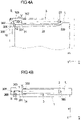
- the section of the linkage 305 above the pivot point 307 tilts in the pivoting direction A1 (in the view according to Figure 4A to the left), the section below the pivot point 307, however, in the pivoting direction A2 (in the view according to Figure 4A to the right), so that the lever 306 in the pivoting direction A3 (see Figure 4B ) is moved in the direction of opening the door 1.
- Extending the push rod 31 thus causes the door 1 to open. If, on the other hand, the push rod 31 is retracted, the door 1 is closed by the lever 306 being pivoted back counter to the pivoting direction A3. A pull on the push rod 31 in the direction of retraction thus causes an opening, while pressure on the push rod causes it to close, with the push rod 31 also being able to be elastically prestressed in the direction of the extension, so that the closing movement is resiliently supported or possibly even after an opening can take place automatically.
- the linkage 305 and the pivot point 307 can optionally also be used to increase or decrease the drive movement of the connecting rod 31 into the pivoting movement of the lever 306 .
- a door lock can also be dispensed with here.
- the inner door is then held in its closed position solely because of the holding forces of the drive device 3 .
- the drive device 3 is designed to be self-locking in the form of a spindle drive, so that the door 1 can only be opened by an electric motor, driven by the drive device 3.
- the drive device 3 not to be designed to be self-locking, so that the door 1 can also be opened manually by moving the door 1, for example for the purpose of an emergency opening.
- a wrap spring brake can be used, for example, as is known, for example, from window lifter drives in automotive engineering.
- Such a wrap spring brake serves as a load torque lock in such a way that a torque introduced on the drive side by the drive device 3 is transmitted and leads to a pivoting of the door 1, while a torque introduced on the output side, i.e. a torque exerted on the door 1 on the output side, is blocked so that a output-side torque can not lead to an adjustment of the door 1.
- the drive device 3 is arranged on a frame section of the frame 2' and acts, according to FIG Figures 3A and 3B described type, on the window 1 'to pivot the window 1' about a pivot axis S a.
- the mode of operation of the drive device 3 is identical to that described above, so that the explanations regarding the design according to FIG Figures 3A and 3B should be referred.
- the drive device 3 acts via the push rod 31 and the link rod 303 on a coupling linkage 11 for coupling the window 1' to the frame 2'.
- the link rod 303 is operatively connected to a lever 110 of the coupling linkage 11 such that when the push rod 31 is extended in the adjustment direction V, the window 1' is tilted about the pivot axis S relative to the frame 2' to open the window 1'.
- the coupling linkage 11 serves in a manner known per se to guide the tilting movement of the window 1' and to limit this tilting movement in order to set a defined opening angle in a tilted position of the window 1' and to hold the window 1' in this tilted position.
- a locking linkage 12 which couples the drive device 3 to a lock 122 .
- the locking linkage 12 has a connecting rod 120 which passes through a slot 308 on the link rod 303, is connected to the push rod 31 and is coupled at its end remote from the slot 308 to a rocker arm 121 pivotable about a pivot point D.
- the long hole 308 is formed on the link rod 303 , and the link rod 303 is coupled to the push rod 31 via the long hole 308 .
- the push rod 31 is connected directly to the connecting rod 120 in such a way that when the push rod 31 moves in the direction of opening the window 1′ from a closed position, the connecting rod 120 is moved to unlock the lock 122, but the articulated rod 303 is initially not moved with it is moved. Only after a predetermined adjustment path of the push rod 31 and a complete unlocking of the lock 122 is the link rod 303 moved in order to pivot the window 1'.
- the mode of operation of the drive device 3 for opening the window 1' is basically the same as above with reference to FIG figure 5 explained.
- the connecting rod 120 of the locking linkage 12 is also moved by coupling via the elongated hole 308, so that the lock 122 is released from a locking position via the rocker arm 121 Placed and the window 1 'is unlocked.
- the coupling between the locking linkage 12 and the push rod 31 or the articulated rod 303 is such that the locking device 122 is first released before the window 1 ′ tilts, so that the locking device 122 initiates a tilting process caused by the drive device 3 of the window 1' is not impeded.
- the lock 122 is brought back into its locking position when the closed position is reached by the coupling linkage 12 being confirmed accordingly.
- a use of a drive device 3 in combination with a locking linkage 12 in 7 The type shown is basically also conceivable for the other designs described above.
- the movement of the push rod 31 can be used to mechanically control a lock to provide additional security for a pivoting element so that locking or unlocking occurs synchronously with the motorized pivoting movement.
- FIGS 8A and 8B show a specific embodiment of a drive device 3 in the form of a spindle drive.
- the drive device 3 has a spindle 32 which extends along a longitudinal axis L, is arranged rotatably on a housing 30 and is connected to a gear 34 and an electric motor 35 .
- the spindle 32 has an external thread on its outer lateral surface, which engages with an internal thread in a bore 313 of a spindle nut 310 .
- the spindle nut 310 is held in a rotationally fixed manner on an (inner) tube of a push rod 31 which is mounted in a cladding tube 312 via an end face 314 facing away from the spindle nut 310 .
- the jacket tube 312 is mounted on the housing 30 so that it can be displaced along the longitudinal axis L (but is non-rotatable), so that the tube 311 is also guided on the housing 30 via the jacket tube 312 .
- the electric motor 35 causes the spindle 32 to rotate about the longitudinal axis L via the gear 34. Due to the threaded engagement of the spindle nut 310 with the spindle 32 and the fixed arrangement of the spindle nut 310 on the connecting rod 31, the spindle nut 310 rolls on of the spindle 32, so that the spindle nut 310 along the longitudinal axis L relative to of the spindle 32 is adjusted and together with the spindle nut 310 the tube 311 and the cladding tube 312 are moved and thus the entire push rod 31 is moved.
- Figure 8A shows the drive device 3 in an extended position, in which the spindle nut 310 is moved to an end of the spindle 32 facing away from the gear 34 .
- Figure 8B on the other hand, the drive device 3 is shown in a retracted position, in which the spindle nut 310 is near the end of the spindle 32 facing the transmission 34 .
- the push rod 31 is prestressed in relation to the housing 30 by a spring 33 in the form of a compression spring and is supported on a support 36 on the housing 30 for this purpose.
- the pretensioning takes place in the direction of the extended position (see Figure 8A ), so that the spring 33 is tensioned under pressure when the push rod 31 is retracted counter to the adjustment direction V, as is shown in Figure 8B is shown.
- the drive device 3 can be moved back in the direction of an initial position, so that, for example, a pivoting element is automatically reset to an initial position, for example a closed position, by the action of the spring 33 after an adjustment becomes.
- the spring 33 can also be dispensed with, in particular if pretensioning in a certain starting position is not desired or if no (significant) weight forces act on a pivoting element that have to be compensated by a spring (as is the case, for example, with a vertically directed Pivoting axis of the pivoting element, for example in the case of a door in 1 illustrated species, is the case).
- a modified embodiment of a drive device 3 in which no spring for biasing a push rod 31 relative to a housing 30 is provided is shown 9 .
- a spindle 32 is rotatably mounted and is in engagement with a gear 34 and an electric motor 35 .
- the spindle 32 is set in a rotational movement such that a spindle nut 310, which is in engagement with an external thread of the spindle 32 and has a bore 313, rolls on the spindle 32 and is moved axially in an adjustment direction V relative to the spindle 32 .
- a tube 311 is coupled to the spindle nut 310, on the end face 314 of which is a coupling point 301 for connection to a connecting rod 303 (see, for example, 1 ) is arranged.
- the tube 311 of the push rod 31 is mounted on the housing 30 in an axially displaceable manner, but is not pretensioned with respect to the housing 30 by a spring. There is also no outer cladding tube, resulting in an overall simple construction.
Landscapes
- Power-Operated Mechanisms For Wings (AREA)
Description
- Die Erfindung betrifft eine Baugruppe einer Tür oder eines Fensters eines Gebäudes.
- Eine derartige Baugruppe weist ein Schwenkelement, einen Rahmen, an dem das Schwenkelement um eine Schwenkachse schwenkbar angeordnet ist, und eine motorische Antriebsvorrichtung, die zum Verschwenken des Schwenkelementes relativ zu dem Rahmen zwischen dem Schwenkelement und dem Rahmen wirkt, auf. Die motorische Antriebsvorrichtung ist durch einen Spindelantrieb mit einer sich entlang einer Längsachse erstreckenden Spindel und einer mit der Spindel in Gewindeeingriff stehenden Spindelmutter ausgebildet.
- Bei dem anspruchsgemäßen Schwenkelement handelt es sich um eine Tür oder ein Fenster eines Gebäudes, also beispielsweise eine Haustür, eine Innentür oder ein Gebäudefenster. Die Antriebsvorrichtung dient zum motorischen Verstellen der Tür oder des Fensters, wobei die Antriebsvorrichtung beispielsweise einen Elektromotor aufweisen kann, der die Spindel und die Spindelmutter des Spindelantriebs zum Verschwenken des Schwenkelements in eine relative Drehbewegung zueinander versetzt, so dass die Spindelmutter an der Spindel abrollt und entlang der Spindel verstellt wird, um auf diese Weise ein Drehmoment zum Verschwenken der Tür oder des Fensters relativ zu dem Rahmen zu übertragen.
- Bei dem Rahmen kann es sich entsprechend um einen Türrahmen oder einen Fensterrahmen handeln.
- Das Schwenkelement dient üblicherweise zum Verschließen einer durch den Rahmen begrenzten Öffnung. Das Schwenkelement weist dabei eine so genante Nebenschließkante, über die das Schwenkelement um die Schwenkachse verschwenkbar an dem Rahmen angeordnet ist, und eine parallel zur Nebenschließkante verlaufende, von der Schwenkachse abliegende Hauptschließkante auf. Der Nebenschließkante und der Hauptschließkante ist jeweils eine Gegenschließkante des Rahmens zugeordnet, der die Nebenschließkante bzw. die Hauptschließkante in einer Schließstellung des Schwenkelements gerade gegenüberliegt. (Es sei angemerkt, dass üblicherweise auch die quer zur Hauptschließkante erstreckten Kanten z.B. oben und unten an einem Türflügel als "Nebenschließkanten" bezeichnet werden. Wenn im Rahmen des vorliegenden Texts von einer Nebenschließkante die Rede ist, soll damit aber die der Hauptschließkante gegenüberliegende Kante des Schwenkelements bezeichnet sein, über die das Schwenkelement um die Schwenkachse verschwenkbar an dem Rahmen angeordnet ist, soweit nicht ausdrücklich anderes angegeben ist.)
- Der Spindelantrieb ist entlang der Längsachse, entlang derer sich die Spindel erstreckt, lagefest an dem Schwenkelement angeordnet. Hierunter ist zu verstehen, dass der Spindelantrieb an dem Schwenkelement angeordnet ist, und zwar derart, dass die Lage der Längsachse an dem Schwenkelement fest ist. Der Spindelantrieb mit der entlang der Längsachse erstreckten Spindel wird somit bei einer Schwenkbewegung des Schwenkelements relativ zu dem Rahmen nicht relativ zu dem Schwenkelement verschwenkt, sondern bleibt lagefest zu dem Bauteil, an dem er angeordnet ist.
- Bei einem aus der
DE 102 13 427 A1 bekannten Antrieb für einen Flügel einer Tür oder eines Fensters ist eine Antriebsvorrichtung in Form eines Spindelantriebs vorgesehen, bei dem eine Spindel zum Verstellen des Flügels verdreht wird, so dass eine mit der Spindel in Gewindeeingriff stehende Spindelmutter an der Spindel abrollt und entlang einer Längsachse, entlang derer die Spindel an einem Rahmen erstreckt ist, bewegt wird. Die Spindelmutter ist über einen Hebel mit dem Flügel gekoppelt und bewegt den Flügel bei ihrer Bewegung entlang der Spindel. - Nachteilig bei dem Antrieb der
DE 102 13 427 A1 ist, dass ein Verschwenken eines Flügels relativ zu einem Rahmen nur um einen vergleichsweise kleinen Winkel möglich ist. Zudem ist ein Hebel erforderlich, der von dem Rahmen vorsteht und mit dem Flügel gekoppelt ist. Dieser Hebel ist von außen deutlich sichtbar und behindert zudem gegebenenfalls bei geöffnetem Flügel einen Durchgriff. - Aus der
DE 197 56 496 C2 ist ein Drehtürantrieb mit einer elektronischen Steuerung bekannt, bei der eine Antriebsvorrichtung in Form eines Spindelantriebs mit einer drehbaren Spindel und einer an der Spindel angeordneten Spindelmutter vorgesehen ist. Im Betrieb bewegt die Spindelmutter eine Zahnstange, die mit einer Antriebsachse in Eingriff steht derart, dass bei einer Bewegung der Zahnstange die Antriebsachse in eine Drehbewegung versetzt wird, über die ein Türflügel verschwenkt werden kann. Herkömmliche Antriebsvorrichtungen zum Verschwenken eines Schwenkelements in Form einer Tür oder eines Fensters eines Gebäudes sind als Aufsatz auf ein Schwenkelement oder einen Rahmen ausgebildet oder verwenden zumindest sichtbare Hebel, die von dem Schwenkelement vorstehen und aus einer Ebene, in der sich das Schwenkelement erstreckt, hinausragen. - Die
DE 101 17 933 A1 offenbart eine automatisch betätigbare Fahrzeugtür (insbesondere eine Heckklappe), bei der ein Verstellantrieb mit einem Spindelantrieb vorgesehen ist. Der Spindelantrieb weist eine drehbare Spindel sowie eine mit der Spindel in Eingriff stehende Mutter auf. Die Spindelmutter ist über eine Gelenkstange mit einem Scharnierbügel gekoppelt, so dass durch Längsverstellen der Spindelmutter die Heckklappe verschwenkt werden kann. - Die
US 7,219,391 B1 offenbart einen Türschließer, der innerhalb eines Türflügels angeordnet ist und der ein Schubelement aufweist, das über eine Gelenkstange an einer Scharnierseite eines Türrahmens abgestützt ist. - Ein aus der
EP 2 196 702 A2 bekannter Spindelantrieb ist beidseitig über Befestigungselemente mit den relativ zueinander verschwenkbaren Bauteilen zu koppeln. - Aufgabe der vorliegenden Erfindung ist es, eine Baugruppe einer Tür oder eines Fensters eines Gebäudes bereitzustellen, die es ermöglicht, bei einfacher Bauweise und zuverlässiger Kraftübertragung auf deutlich sichtbare, aus der Ebene eines Schwenkelementes herausragende Hebel zu verzichten.
- Diese Aufgabe wird durch einen Gegenstand mit den Merkmalen des Anspruchs 1 gelöst.
- Demnach weist der Spindelantrieb eine sich entlang der Längsachse erstreckende Schubstange auf, die, angetrieben durch eine Relativbewegung der Spindel zur Spindelmutter, an dem Schwenkelement entlang der Längsachse verschiebbar und über eine gelenkig mit der Schubstange verbundene Gelenkstange mit dem Rahmen gekoppelt ist, um durch Verschieben der Schubstange das Schwenkelement relativ zu dem Rahmen zu verschwenken.
- Die vorliegende Erfindung geht von dem Gedanken aus, unter Verwendung eines Spindelantriebs mit einer entlang einer Längsachse erstreckten Spindel eine ebenfalls entlang der Längsachse erstreckte Schubstange zum Verschwenken des Schwenkelements anzutreiben. Die Schubstange wird zum Verschwenken des Schwenkelements entlang der Längsachse bewegt und ist über eine Gelenkstange mit dem Rahmen gekoppelt.
- Weil die Schubstange ausschließlich entlang der Längsachse bewegt wird und über die Kopplung der Gelenkstange das Drehmoment zum Verschwenken des Schwenkelements überträgt, kann die Bewegung der Schubstange in der Ebene des Schwenkelements erfolgen, ohne dass ein Hebel zur Kraftübertragung von dem Schwenkelement oder dem Rahmen sichtbar nach außen vorsteht.
- Die Antriebsvorrichtung in Form des Spindelantriebs ist an dem Schwenkelement angeordnet. Der Spindelantrieb ist innerhalb eines Körpers des Schwenkelements, beispielsweise innerhalb eines Türblattes, angeordnet.
- Die Längsachse, entlang derer sich die Schubstange erstreckt, ist vorteilhafterweise senkrecht zur Schwenkachse gerichtet, um die das Schwenkelement schwenkbar an dem Rahmen angeordnet ist. Die Längsachse und damit die Spindel des Spindelantriebs und die Schubstange erstrecken sich somit senkrecht zur Schwenkachse, wobei der Spindelantrieb bei einem Verschwenken des Schwenkelements lagefest mit dem Schwenkelement mitverschwenkt wird.
- Die Schubstange wirkt über eine Nebenschließkante des Schwenkelements, über die das Schwenkelement schwenkbar an dem Rahmen angeordnet ist und die parallel zur Schwenkachse gerichtet ist, zwischen dem Schwenkelement und dem Rahmen. Das Drehmoment zum Verschwenken des Schwenkelements wird somit im Bereich der Nebenschließkante - also an der Kante des Schwenkelements, über die das Schwenkelement die verschwenkbar an dem Rahmen angeordnet ist - erzeugt. Dadurch, dass die Schubstange über die Nebenschließkante wirkt, ist der freie Erstreckungsweg, über den die Schubstange und/oder die Gelenkstange sich zwischen dem Schwenkelement und dem Rahmen frei und sichtbar erstrecken, kurz, weil im Bereich der Nebenschließkante der Abstand zwischen dem Schwenkelement und dem Rahmen klein ist.
- Die Gelenkstange tritt an der Nebenschließkante aus dem Schwenkelement aus, und die Schubstange ist über die Gelenkstange gelenkig an einer der Nebenschließkante gegenüberliegenden Gegenschließkante des Rahmens abgestützt. Die Schubstange bildet somit zusammen mit der Gelenkstange ein Hebelgetriebe zwischen der Nebenschließkante des Schwenkelements und der zugeordneten Gegenschließkante des Rahmens, das derart ausgestaltet ist, dass bei einer Verschiebebewegung der Schubstange entlang der senkrecht zur Schwenkachse gerichteten Längsachse in der Ebene des Schwenkelements ein Drehmoment zwischen dem Schwenkelement und dem Rahmen bewirkt wird, das zu einem Verschwenken des Schwenkelements relativ zu dem Rahmen führt. Über die Schubstange und die Gelenkstange drückt sich das Schwenkelement sozusagen von dem Rahmen ab und wird aufgrund der Verschiebebewegung der Schubstange verschwenkt.
- Die Gelenkstange ist hierbei gelenkig sowohl mit der Gegenschließkante des Rahmens als auch mit der Schubstange verbunden, wobei an der Schubstange eine geeignete, gegebenenfalls lösbare Koppelstelle zur gelenkigen Verbindung mit der Gelenkstange und an der Gegenschließkante ein geeignetes Lager zur gelenkigen Anordnung der Gelenkstange vorgesehen ist.
- Über die motorische Antriebsvorrichtung kann das Schwenkelement in elektromotorisch angetriebener Weise relativ zu dem Rahmen verschwenkt werden. Die motorische Antriebsvorrichtung kann hierbei so ausgestaltet sein, dass sie das Schwenkelement, also beispielsweise die Tür oder das Fenster eines Gebäudes, in einer Schließstellung, in der die durch den Rahmen begrenzte Öffnung durch das Schwenkelement verschlossen ist, in Position hält. Grundsätzlich könnte damit auf eine gesonderte Verrieglung, beispielsweise ein Türschloss, verzichtet werden.
- Es ist möglich, den Spindelantrieb selbsthemmend oder auch nicht selbsthemmend auszugestalten. Ist der Spindelantrieb selbsthemmend ausgestaltet, so kann das Schwenkelement nur elektromotorisch verstellt werden, angetrieben durch die motorische Antriebsvorrichtung, während ein manuelles Verstellen durch Druck oder Zug an dem Schwenkelement durch den selbsthemmenden Spindelantrieb verhindert ist. Ist der Spindelantrieb hingegen nicht selbsthemmend ausgestaltet, so ist eine Öffnung durch manuelles Bewegen des Schwenkelements, beispielsweise der Tür oder des Fensters, bei Aufbringen einer hinreichenden Kraft möglich, so dass beispielsweise eine Notöffnung einer Tür oder eines Fensters vorgenommen werden kann.
- In einer Weiterbildung kann die Schubstange mit einem Verrieglungsgestänge zum Verriegeln oder Entriegeln des Schwenkelements relativ zu dem Rahmen in Abhängigkeit von der Stellung der Schubstange gekoppelt sein. Diesem liegt der Gedanke zugrunde, die Antriebsvorrichtung nicht nur zum Verschwenken des Schwenkelements zu verwenden, sondern auch zum (mechanischen) Steuern einer Verrieglung des Schwenkelements einzusetzen. Über das Verrieglungsgestänge wird bei Beginn einer Schwenkbewegung zum Öffnen des Schwenkelements aus einer Schließstellung dann die Verriegelung so betätigt, dass die Verrieglung gelöst und das Schwenkelement entriegelt wird. Umgekehrt wird die Verrieglung hergestellt, wenn die Schubstange zum Schließen des Schwenkelements verfahren wird und das Schwenkelement in seine Schließstellung gelangt. Auf diese Weise werden eine sichere Verriegelung und damit ein sicherer Halt des Schwenkelements in seiner Schließstellung an dem Rahmen gewährleistet.
- Grundsätzlich sind für die Antriebsvorrichtung der hier genannten Art unterschiedliche Ausführungsformen von Spindelantrieben im Rahmen der Ansprüche denkbar und einsetzbar. Die Spindel ist drehbar an einem Gehäuse des Spindelantriebs angeordnet und mit einem Elektromotor zum Antreiben der Spindel ir Wirkverbindung. Die Spindelmutter ist hierbei drehfest an einem verschiebbar an dem Gehäuse gelagerten Rohr der Schubstange angeordnet derart, dass bei einer Drehbewegung der Spindel die Spindelmutter zusammen mit dem Rohr entlang der Längsachse relativ zu dem Gehäuse verschoben wird. Durch Verdrehen der Spindel, angetrieben durch den Elektromotor, rollt somit die Spindelmutter (die drehfest an dem Rohr der Schubstange angeordnet ist) an der Spindel ab, so dass aufgrund des Gewindeeingriffs der Spindelmutter mit der Spindel die Spindelmutter entlang der Längsachse, entlang derer sich die Spindel erstreckt, relativ zu der Spindel verstellt wird und damit die Schubstange relativ zu der Spindel verfahren wird.
- Der Elektromotor kann hierbei koaxial zur Spindel in dem Gehäuse angeordnet sein, so dass sich eine schlanke, längs entlang der Längsachse erstreckte Bauform des Spindelantriebs mit geringem Bauraumbedarf ergibt.
- Die Schubstange ist vorteilhafterweise über eine Feder gegenüber dem Gehäuse vorgespannt. Hierdurch kann erreicht werden, dass (beispielsweise bei einer nicht selbsthemmenden Ausgestaltung des Spindelantriebs) das Schwenkelement nach einem Verschwenken selbsttätig in eine Ausgangslage zurückverschwenkt wird. Beispielsweise kann die Feder die Schubstange in Richtung einer ausgefahrenen Stellung vorspannen, in der die Schubstange aus dem Gehäuse, an dem die Spindel angeordnet ist, ausgefahren ist. Wirkt beispielsweise eine Gewichtskraft eines Schwenkelements in Form eines Kippfensters in Richtung eines Einfahrens auf die Schubstange ein, so kann durch die vorspannende Feder diese Gewichtskraft ausgeglichen werden, so dass das Kippfenster über den Spindelantrieb sicher abgestützt und gehalten werden kann.
- Wirken keine nennenswerten Gewichtskräfte um die Schwenkachse auf das Schwenkelement ein und ist eine Vorspannung in eine bestimmte Stellung des Schwenkelements nicht erwünscht, so kann auf die vorspannende Feder auch verzichtet werden.
- Der der Erfindung zugrundeliegende Gedanke soll nachfolgend anhand der in den Figuren dargestellten Ausführungsbeispiele näher erläutert werden. Es zeigen:
- Fig. 1
- eine schematische Ansicht eines Ausführungsbeispiels einer Antriebsvorrichtung, angeordnet an einem Schwenkelement in Form einer Tür, gesehen von oben;
- Fig. 2
- eine schematische Ansicht des Ausführungsbeispiels gemäß
Fig. 1 , bei geöffnetem Schwenkelement; - Fig. 3A
- eine schematische Ansicht einer anderen, nicht anspruchsgemäßen, an einem Rahmen angeordneten Antriebsvorrichtung, betrachtet von der Seite in teilweise freigeschnittener Weise;
- Fig. 3B
- eine schematische Ansicht der Antriebsvorrichtung gemäß
Fig. 3A , betrachtet von oben; - Fig. 4A
- eine schematische Ansicht einer weiteren, nicht anspruchsgemäßen, an einem Rahmen angeordneten Antriebsvorrichtung, betrachtet von der Seite;
- Fig. 4B
- eine schematische Ansicht der Antriebsvorrichtung gemäß
Fig. 4A , betrachtet von oben; - Fig. 5
- eine schematische Ansicht einer nicht anspruchsgemäßen Bauform einer Antriebsvorrichtung an einem Fenster;
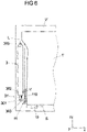
- Fig. 6
- eine schematische Ansicht einer weiteren nicht anspruchsgemäßen Bauform einer Antriebsvorrichtung an einem Fenster;
- Fig. 7
- eine schematische Ansicht einer nicht anspruchsgemäßen Bauform einer Antriebsvorrichtung an einem Fenster, gekoppelt mit einem Verrieglungsgestänge;
- Fig. 8A
- eine schematische Ansicht einer Antriebsvorrichtung in Form eines Spindelantriebs, dargestellt in einer ausgefahrenen Stellung;
- Fig. 8B
- eine schematische Ansicht der Antriebsvorrichtung gemäß
Fig. 8A , in einer eingefahrenen Stellung, und - Fig. 9
- eine schematische Ansicht eines modifizierten Ausführungsbeispiels einer Antriebsvorrichtung in Form eines Spindelantriebs.
-
Fig. 1 und 2 zeigen in schematischen Ansichten ein Ausführungsbeispiel einer Baugruppe, die aus einem Schwenkelement in Form einer schwenkbar an einem Rahmen 2 angeordneten Tür 1 und einer an der Tür 1 angeordneten Antriebsvorrichtung 3 zum motorischen Verschwenken der Tür 1 relativ zu dem Rahmen 2 gebildet ist. - Bei der Tür kann es sich beispielsweise um eine Außentür oder eine Innentür eines Gebäudes handeln, die eine durch den Rahmen 2 begrenzte Türöffnung in einer Schließstellung (schematisch dargestellt in
Fig. 1 ) verschließt. - Die Antriebsvorrichtung 3 ist nach Art eines Spindelantriebs ausgebildet und, bei dem in
Fig. 1 und 2 dargestellten Ausführungsbeispiel, an dem Schwenkelement in Form der Tür 1 angeordnet. Die Antriebsvorrichtung 3 ist hierbei in oder an einem Körper 13 in Form eines Türblatts der Tür 1 angeordnet, beispielsweise in den Körper 13 eingelassen, und weist eine Schubstange 31 auf, die über eine Spindel und eine Spindelmutter der Antriebsvorrichtung 3 zum Verschwenken der Tür 1 angetrieben wird, wie nachfolgend noch im Einzelnen erläutert werden soll. - Die Antriebsvorrichtung 3 ist über ein Festlager 300 und ein seitliches Lager 302 lagefest an der Tür 1 angeordnet. Die Schubstange 31 ist hierbei entlang einer Längsachse L erstreckt und entlang dieser Längsachse L an der Tür 1 verschiebbar und weist eine Koppelstelle 301 auf, an die eine Gelenkstange 303 angebunden ist. Die Gelenkstange 303 ist an ihrem der Schubstange 31 abgewandten Ende an einem Lager 304 an einer Gegenschließkante 20 des Rahmens abgestützt, über die auch die Tür 1 über ein oder mehrere Scharniere 10 um eine Schwenkachse S schwenkbar angeordnet ist.
- Die Gegenschließkante 20 des Rahmens 2 ist einer Nebenschließkante 14 der Tür 1 zugeordnet und parallel zu dieser Nebenschließkante 14 erstreckt. Die Nebenschließkante 14 erstreckt sich entlang einer Vertikalrichtung Z, und über die Nebenschließkante 14 ist die Tür um die Schwenkachse S verschwenkbar an dem Rahmen 2 angeordnet. Die von der Schwenkachse S abliegende, parallel zur Nebenschließkante 14 gerichtete Kante 15 der Tür 1 wird als Hauptschließkante bezeichnet und ist einer weiteren Gegenschließkante 21 an dem Rahmen 2 zugeordnet.
- Zum Verschwenken der Tür 1 relativ zu dem Rahmen 2 wird die Schubstange 31 in eine Verstellrichtung V aus der Antriebsvorrichtung 3 in Form des Spindelantriebs ausgefahren, so dass über die Kopplung mittels der Gelenkstange 303 die Tür 1 an der Gegenschließkante 20 abgedrückt wird und ein Drehmoment um die Schwenkachse S auf die Tür 1 zum Öffnen der Tür 1 in eine Öffnungsrichtung O (siehe
Fig. 2 ) ausgeübt wird. - Die Bewegung der Schubstange 31 erfolgt entlang der Längsachse L und somit (zumindest weitestgehend) innerhalb des Körpers 13 der Tür 1, wobei die Gelenkstange 303 an der der Gegenschließkante 20 zugewandten Nebenschließkante 14 aus dem Körper 13 austritt. Die offene Wegstrecke, entlang derer die Gelenkstange 303 und/oder die Schubstange 31 frei zwischen der Tür 1 und dem Rahmen 2 verläuft, ist somit kurz, so dass die Gelenkstange 303 und/oder die Schubstange 31 von außen kaum sichtbar sind.
- Zusätzlich zu der Antriebsvorrichtung 3 kann auch eine Steuerelektronik innerhalb des Körpers 13 in Form des Türblattes angeordnet sein, so dass weder die Antriebsvorrichtung 3 noch die Steuerelektronik von außen sichtbar sind.
- Denkbar ist auch, eine Steuerelektronik in oder an dem Rahmen 2 anzuordnen.
- Die in
Fig. 1 und 2 dargestellte Anordnung der Antriebsvorrichtung 3 hat den weiteren Vorteil, dass ein Verschwenken der Tür 1 um einen großen Öffnungswinkel möglich ist, insbesondere einen Öffnungswinkel größer als 90°. - Ein andere, nicht anspruchsgemäße Bauform zeigen
Fig. 3A und 3B . Bauteile gleicher Funktion sollen hierbei, soweit zweckdienlich, wie auch in den nachfolgenden weiteren Bauformen mit gleichen Bezugszeichen wie vorangehend bezeichnet werden. - Bei der Bauform gemäß
Fig. 3A und 3B ist eine Antriebsvorrichtung 3 in Form eines Spindelantriebs an einem Rahmen 2 untergebracht, an dem eine Tür 1 um eine Schwenkachse S über ein Scharnier 10 schwenkbar angeordnet ist, und hierzu innerhalb eines Rahmenabschnitts 23 in Form einer Türzarge eingefasst. Die Antriebsvorrichtung 3 weist eine Schubstange 31 auf, die über eine Koppelstelle 301 mit einer Gelenkstange 303 gekoppelt und entlang einer Längsachse L verschiebbar ist. - Bei der Bauform gemäß
Fig. 3A und 3B ist die Gelenkstange 303 über eine Lagerstelle 303A mit einem Gestänge 305 verbunden, das über einen Hebel 306 an dem Schwenkelement in Form der Tür 1 angreift. Über das Gestänge 305 ist die Gelenkstange 303 mit dem Hebel 306 gekoppelt, wobei der Hebel 306 drehfest mit dem Schwenkelement in Form der Tür 1 verbunden ist, so dass eine Verstellbewegung der Schubstange 31 in eine Verschwenkbewegung der Tür 1 umgesetzt wird. Der Hebel 306 ist am unteren Ende des Gestänges 305 angeordnet und greift im Bereich eines Scharniers 10 an der Tür 1 an. - Im Betrieb wird die Schubstange 31, angetrieben durch die Antriebsvorrichtung 3, entlang der Längsachse L (Verstellrichtung V) verfahren, so dass über die Gelenkstange 303 und den Hebel 306 ein Drehmoment auf die Tür 1 ausgeübt und diese relativ zum Rahmen 2 verschwenkt wird. Die Anordnung ist dabei derart, dass bei einem Einfahren der Schubstange 31 entgegen der Verstellrichtung V die Tür 1 in die Öffnungsrichtung O geöffnet wird, indem der Hebel 306 hin zu der Antriebsvorrichtung 3 gezogen wird. Das Schließen der Tür 1 erfolgt in umgekehrter Richtung, indem die Schubstange 31 in die Verstellrichtung V aus der Antriebsvorrichtung 3 ausgefahren wird.
- Bei der nicht anspruchgemäßen Bauform gemäß
Fig. 4A und 4B ist, im Unterschied zu der Bauform gemäßFig. 3A und 3B , das Gestänge 305 durch einen zusätzlichen Drehpunkt 307 in Form eines Lagers an dem Türrahmen 2 gelagert. Dadurch ergibt sich eine Umkehr der Bewegungsrichtung der Antriebsbewegung, verglichen mit der Bauform gemäßFig. 3A und 3B (bezogen auf die Bewegung der Tür 1), und damit gegebenenfalls eine bessere Kraftausnutzung. - Das Gestänge 305 ist an seinem oberen Ende gelenkig mit der Gelenkstange 303 und an seinem unteren Ende gelenkig mit dem Hebel 306 verbunden.
- Wird im Betrieb die Schubstange 31 in die Verstellrichtung V ausgefahren, so wird das Gestänge 305 um den Drehpunkt 307 verkippt. Dabei verkippt der Abschnitt des Gestänges 305 oberhalb des Drehpunkts 307 in die Verschwenkrichtung A1 (in der Ansicht gemäß
Fig. 4A nach links), der Abschnitt unterhalb des Drehpunkts 307 hingegen in die Verschwenkrichtung A2 (in der Ansicht gemäßFig. 4A nach rechts), so dass der Hebel 306 in die Verschwenkrichtung A3 (sieheFig. 4B ) in Richtung eines Öffnens der Tür 1 bewegt wird. - Ein Ausfahren der Schubstange 31 bewirkt somit ein Öffnen der Tür 1. Wird hingegen die Schubstange 31 eingefahren, so wird die Tür 1 geschlossen, indem der Hebel 306 entgegen der Verschwenkrichtung A3 zurückverschwenkt wird. Ein Zug an der Schubstange 31 in Richtung des Einfahrens bewirkt somit ein Öffnen, ein Druck an der Schubstange hingegen ein Schließen, wobei die Schubstange 31 zusätzlich in Richtung des Ausfahrens elastisch vorgespannt sein kann, so dass die Schließbewegung federelastisch unterstützt oder gegebenenfalls nach einem Öffnen sogar selbsttätig erfolgen kann.
- Über das Gestänge 305 und den Drehpunkt 307 kann gegebenenfalls auch eine Über-oder Untersetzung der Antriebsbewegung der Schubstange 31 in die Verschwenkbewegung des Hebels 306 eingestellt werden.
- Die vorangehend beschriebenen Bauformen lassen sich bei Außentüren und Innentüren in Gebäuden einsetzen. Grundsätzlich, insbesondere bei einem Einsatz bei einer Innentür, kann hierbei auch auf ein Türschloss verzichtet werden. Die Innentür wird dann lediglich aufgrund der Haltekräfte der Antriebsvorrichtung 3 in ihrer Schließstellung gehalten.
- Denkbar ist hierbei, dass die Antriebsvorrichtung 3 in Form des Spindelantriebs selbsthemmend ausgebildet ist, so dass ein Öffnen der Tür 1 ausschließlich elektromotorisch möglich ist, angetrieben durch die Antriebsvorrichtung 3.
- Denkbar ist aber auch, die Antriebsvorrichtung 3 nicht selbsthemmend auszugestalten, so dass auch manuell durch Bewegen der Tür 1 ein Öffnen der Tür 1, beispielsweise zum Zwecke einer Notöffnung, möglich ist.
- Gegebenenfalls ist auch möglich, zusätzlich eine weitere Bremse vorzusehen, die ein ungewünschtes Verstellen der Tür 1 bei Kraftwirkung auf die Tür 1 verhindert, insbesondere bei einer nicht durch die Antriebsvorrichtung 3 bewirkten, an der Tür 1 angreifenden Kraft. Zu diesem Zwecke kann beispielsweise eine Schlingfederbremse eingesetzt werden, wie sie beispielsweise von Fensterheberantrieben aus der Kraftfahrzeugtechnik bekannt ist. Eine solche Schlingfederbremse dient als Lastmomentensperre derart, dass ein antriebsseitig durch die Antriebsvorrichtung 3 eingeleitetes Drehmoment übertragen wird und zu einem Verschwenken der Tür 1 führt, ein abtriebsseitig eingeleitetes Drehmoment, also ein abtriebsseitig auf die Tür 1 ausgeübtes Drehmoment, hingegen gesperrt wird, so dass ein abtriebsseitiges Drehmoment nicht zu einem Verstellen der Tür 1 führen kann.
- Bei der in
Fig. 5 dargestellten nicht anspruchgemäßen Bauform ist eine Antriebsvorrichtung 3 an einem Rahmer 2' eines Schwenkelements in Form eines Fensters 1' eines Gebäudes eingesetzt. Die Antriebsvorrichtung 3 ist an einem Rahmenabschnitt des Rahmen 2' angeordnet und wirkt, nach der anhand vonFig. 3A und 3B beschriebenen Art, auf das Fenster 1' zum Verschwenken des Fensters 1' um eine Schwenkachse S ein. Die Funktionsweise der Antriebsvorrichtung 3 ist identisch wie vorangehend beschrieben, so dass auf die Ausführungen zur Bauform gemäßFig. 3A und 3B verwiesen werden soll. - Bei einer gegenüber der Bauform nach
Fig. 5 nur geringfügig modifizierten Bauform, dargestellt inFig. 6 , wirkt die Antriebsvorrichtung 3 über die Schubstange 31 und die Gelenkstange 303 auf ein Kopplungsgestänge 11 zum Koppeln des Fensters 1' mit dem Rahmen 2' ein. Die Gelenkstange 303 steht hierzu mit einem Hebel 110 des Kopplungsgestänges 11 in Wirkverbindung derart, dass bei einem Ausfahren der Schubstange 31 in die Verstellrichtung V das Fenster 1' um die Schwenkachse S relativ zu dem Rahmen 2' zum Öffnen des Fensters 1' verkippt wird. Das Kopplungsgestänge 11 dient hierbei in an sich bekannter Weise zum Führen der Kippbewegung des Fensters 1' und zum Begrenzen dieser Kippbewegung, um einen definierten Öffnungswinkel in einer verkippten Stellung des Fensters 1' festzulegen und das Fenster 1' in dieser verkippten Stellung zu halten. - Bei einer weiteren nicht anspruchgemäßen Bauform, dargestellt in
Fig. 7 , ist - in Weiterbildung der Bauform gemäßFig. 5 - zusätzlich ein Verrieglungsgestänge 12 vorgesehen, das die Antriebsvorrichtung 3 mit einer Verriegelung 122 koppelt. Das Verriegelungsgestänge 12 weist hierzu eine Verbindungsstange 120 auf, die ein Langloch 308 an der Gelenkstange 303 durchgreift, mit der Schubstange 31 verbunden ist und an ihrem dem Langloch 308 abgewandten Ende mit einem um einen Drehpunkt D schwenkbaren Kipphebel 121 gekoppelt ist. - Das Langloch 308 ist an der Gelenkstange 303 ausgebildet, und die Gelenkstange 303 ist über das Langloch 308 mit der Schubstange 31 gekoppelt. Die Schubstange 31 ist direkt mit der Verbindungsstange 120 verbunden derart, dass bei einer Bewegung der Schubstange 31 in Richtung eines Öffnens des Fensters 1' aus einer geschlossenen Stellung die Verbindungsstange 120 zum Entriegeln der Verriegelung 122 bewegt wird, dabei aber die Gelenkstange 303 zunächst nicht mit bewegt wird. Erst nach einem vorbestimmten Verstellweg der Schubstange 31 und einer vollständigen Entriegelung der Verriegelung 122 wird die Gelenkstange 303 bewegt, um das Fenster 1' zu verschwenken.
- Die Funktionsweise der Antriebsvorrichtung 3 zum Öffnen des Fensters 1' ist grundsätzlich wie vorangehend anhand von
Fig. 5 erläutert. Zusätzlich wird jedoch bei einem Ausfahren der Schubstange 31 in die Verstellrichtung V zum Verkippen des Fensters 1' um die Schwenkachse S durch Kopplung über das Langloch 308 auch die Verbindungsstange 120 des Verriegelungsgestänges 12 bewegt, so dass über den Kipphebel 121 die Verriegelung 122 aus einer verriegelnden Stellung gebracht und das Fenster 1' damit entriegelt wird. Die Kopplung zwischen dem Verriegelungsgestänge 12 und der Schubstange 31 bzw. der Gelenkstange 303 ist dabei derart, dass die Verriegelung 122 zunächst gelöst wird, bevor es zu einem Verkippen des Fensters 1' kommt, so dass die Verriegelung 122 einen durch die Antriebsvorrichtung 3 bewirkten Kippvorgang des Fensters 1' nicht behindert. - Wird das Fenster 1' umgekehrt durch Einfahren der Schubstange 31 entgegen der Verstellrichtung V wieder in seine geschlossene Stellung gebracht, so wird bei Erreichen der geschlossenen Stellung die Verriegelung 122 wieder in ihre verriegelnde Stellung gebracht, indem das Kopplungsgestänge 12 entsprechend bestätigt wird.
- Eine Verwendung einer Antriebsvorrichtung 3 in Kombination mit einem Verriegelungsgestänge 12 der in
Fig. 7 dargestellten Art ist grundsätzlich auch bei den anderen vorangehend beschriebenen Bauformen denkbar. Allgemein kann die Bewegung der Schubstange 31 dazu genutzt werden, eine Verriegelung zum Bereitstellen einer zusätzlichen Sicherung für ein Schwenkelement mechanisch zu steuern, so dass ein Verriegeln oder ein Entriegeln synchron mit der motorisch angetriebenen Schwenkbewegung erfolgt. -
Fig. 8A und 8B zeigen ein konkretes Ausführungsbeispiel einer Antriebsvorrichtung 3 in Form eines Spindelantriebs. Die Antriebsvorrichtung 3 weist eine Spindel 32 auf, die sich entlang einer Längsachse L erstreckt, drehbar an einem Gehäuse 30 angeordnet ist und mit einem Getriebe 34 und einem Elektromotor 35 in Verbindung steht. - Die Spindel 32 weist an ihrer äußeren Mantelfläche ein Außengewinde auf, das mit einem Innengewinde an einer Bohrung 313 einer Spindelmutter 310 in Eingriff steht. Die Spindelmutter 310 ist drehfest an einem (Innen-)Rohr einer Schubstange 31 gehalten, das über eine von der Spindelmutter 310 abgewandte Stirnseite 314 in einem Hüllrohr 312 gelagert ist. Das Hüllrohr 312 ist an dem Gehäuse 30 entlang der Längsachse L verschiebbar (aber drehfest) gelagert, so dass über das Hüllrohr 312 auch das Rohr 311 an dem Gehäuse 30 geführt ist.
- An der Stirnseite 314 der Schubstange 31 ist eine Koppelstelle 301 zum Koppeln der Schubstange 31 mit der Gelenkstange 303 (siehe das Ausführungsbeispiel gemäß
Fig. 1 ) angeordnet. - Im Betrieb der Antriebsvorrichtung 3 versetzt der Elektromotor 35 über das Getriebe 34 die Spindel 32 in eine Drehbewegung um die Längsachse L. Aufgrund des Gewindeeingriffs der Spindelmutter 310 mit der Spindel 32 und der feststehenden Anordnung der Spindelmutter 310 an der Schubstange 31 rollt die Spindelmutter 310 an der Spindel 32 ab, so dass die Spindelmutter 310 entlang der Längsachse L relativ zu der Spindel 32 verstellt wird und zusammen mit der Spindelmutter 310 das Rohr 311 und das Hüllrohr 312 verfahren werden und somit die gesamte Schubstange 31 bewegt wird.
-
Fig. 8A zeigt hierbei die Antriebsvorrichtung 3 in einer ausgefahrenen Stellung, bei der die Spindelmutter 310 an ein dem Getriebe 34 abgewandtes Ende der Spindel 32 verfahren ist.Fig. 8B hingegen zeigt die Antriebsvorrichtung 3 in einer eingefahrenen Stellung, bei der die Spindelmutter 310 dem Getriebe 34 zugewandeten Ende der Spindel 32 angenähert ist. - Die Schubstange 31 ist über eine Feder 33 in Form einer Druckfeder gegenüber dem Gehäuse 30 vorgespannt und dazu an einer Abstützung 36 an dem Gehäuse 30 abgestützt. Die Vorspannung erfolgt dabei in Richtung der ausgefahrenen Stellung (siehe
Fig. 8A ), so dass die Feder 33 bei einem Einfahren der Schubstange 31 entgegen der Verstellrichtung V auf Druck gespannt wird, wie dies inFig. 8B dargestellt ist. - Mittels der Feder 33 kann, insbesondere bei einer nicht selbsthemmenden Ausgestaltung der Antriebsvorrichtung 3, ein Rückverstellen der Antriebsvorrichtung 3 in Richtung einer Ausgangsstellung bewirkt werden, so dass beispielsweise ein Schwenkelement durch Wirkung der Feder 33 nach einem Verstellen automatisch in eine Ausgangsstellung, beispielsweise eine Schließstellung zurückverstellt wird.
- Ebenso ist möglich, mittels der Feder 33 auf ein Schwenkelement wirkende Gewichtskräfte auszugleichen. Dies kann insbesondere dann von Vorteil sein, wenn (wie bei einem Kippfenster der in
Fig. 5 dargestellten Art) auf das Schwenkelement wirkende Gewichtskräfte auch auf die Antriebsvorrichtung 3 wirken. Diese Gewichtskräfte können durch eine geeignete Vorspannung ausgeglichen werden, so dass es aufgrund von Gewichtskräften nicht zu einem selbsttätigen Verstellen des Schwenkelements kommen kann. - Gegebenenfalls kann auf die Feder 33 auch verzichtet werden, insbesondere dann, wenn eine Vorspannung in eine bestimmte Ausgangsstellung nicht gewünscht ist oder wenn keine (nennenswerten) Gewichtskräfte auf ein Schwenkelement wirken, die durch eine Feder ausgeglichen werden müssen (wie dies beispielsweise bei einer vertikal gerichteten Schwenkachse des Schwenkelements, beispielsweise bei einer Tür der in
Fig. 1 dargestellten Art, der Fall ist). - Ein modifiziertes Ausführungsbeispiel einer Antriebsvorrichtung 3, bei der keine Feder zum Vorspannen einer Schubstange 31 gegenüber einem Gehäuse 30 vorgesehen ist, zeigt
Fig. 9 . Bei dem modifizierten Ausführungsbeispiel ist, wie bei dem Ausführungsbeispiel gemäßFig. 8A und 8B , eine Spindel 32 drehbar gelagert und steht mit einem Getriebe 34 und einem Elektromotor 35 in Eingriff. Im Betrieb der Antriebsvorrichtung 3 wird die Spindel 32 in eine Drehbewegung versetzt derart, dass eine mit einem Außengewinde der Spindel 32 in Eingriff stehende, eine Bohrung 313 aufweisende Spindelmutter 310 an der Spindel 32 abrollt und entlang einer Verstellrichtung V axial relativ zur Spindel 32 bewegt wird. - Mit der Spindelmutter 310 ist ein Rohr 311 gekoppelt, an dessen Stirnseite 314 eine Koppelstelle 301 zur Verbindung mit einer Gelenkstange 303 (siehe beispielsweise
Fig. 1 ) angeordnet ist. - Das Rohr 311 der Schubstange 31 ist axial verschieblich an dem Gehäuse 30 gelagert, dabei aber nicht über eine Feder gegenüber dem Gehäuse 30 vorgespannt. Auch ein äußeres Hüllrohr ist nicht vorhanden, so dass sich ein insgesamt einfacher Aufbau ergibt.
- Die Funktionsweise der Antriebsvorrichtung ist ansonsten identisch wie anhand von
Fig. 8A und 8B beschrieben, so dass auf die vorangehenden Ausführungen verwiesen werden soll. - Der der Erfindung zugrunde liegende Gedanke ist nicht auf die vorangehend geschilderten Ausführungsbeispiele beschränkt, sondern lässt sich auch in grundsätzlich anders gearteten Ausführungsformen im Rahmen der Ansprüche verwirklichen.
-
- 1
- Türflügel
- 1'
- Fenster
- 10
- Gelenk
- 11
- Kopplungsgestänge
- 110
- Hebel
- 12
- Verriegelungsgestänge
- 120
- Verbindungsstange
- 121
- Kipphebel
- 122
- Verriegelung
- 13
- Körper
- 14
- Nebenschließkante
- 15
- Hauptschließkante
- 2
- Türrahmen
- 2'
- Fensterrahmen
- 20
- Gegenschließkante
- 21
- Gegenschließkante
- 23
- Rahmenabschnitt
- 3
- Antriebsvorrichtung
- 30
- Gehäuse
- 300
- Festlager
- 301
- Koppelstelle
- 302
- Seitliches Lager
- 303
- Gelenkstange
- 303A
- Lagerstelle
- 304
- Lager
- 305
- Gestänge
- 306
- Hebel
- 307
- Drehpunkt
- 308
- Langloch
- 31
- Schubstange
- 310
- Spindelmutter
- 311
- Rohr
- 312
- Hüllrohr
- 313
- Bohrung
- 314
- Stirnseite
- 32
- Spindel
- 33
- Druckfeder
- 34
- Getriebe
- 35
- Elektromotor
- 36
- Abstützung
- A1, A2, A3
- Schwenkrichtung
- D
- Drehpunkt
- L
- Längsachse
- O
- Öffnungsrichtung
- S
- Schwenkachse
- V
- Verstellrichtung
- X
- Horizontalrichtung
- Y
- Querrichtung
- Z
- Vertikalrichtung
Claims (5)
- Baugruppe einer Tür oder eines Fensters eines Gebäudes, mit- einem Schwenkelement (1, 1'),- einem Rahmen (2, 2'), an dem das Schwenkelement (1, 1') um eine Schwenkachse (S) schwenkbar angeordnet ist, und- einer motorischen Antriebsvorrichtung, die zum Verschwenken des Schwenkelements (1, 1') relativ zu dem Rahmen (2, 2') zwischen dem Schwenkelement (1, 1') und dem Rahmen (2, 2') wirkt und durch einen Spindelantrieb (3) mit einer sich entlang einer Längsachse (L) erstreckenden Spindel (32) und einer mit der Spindel (32) in Gewindeeingriff stehenden Spindelmutter (310) ausgebildet ist, wobei der Spindelantrieb (3) entlang der Längsachse (L) lagefest an dem Schwenkelement (1, 1') angeordnet ist,wobei der Spindelantrieb (3) eine sich entlang der Längsachse (L) erstreckende Schubstange (31) aufweist, die, angetrieben durch eine Relativbewegung der Spindel (32) zur Spindelmutter (310), an dem Schwenkelement (1, 1') entlang der Längsachse (L) verschiebbar und über eine gelenkig mit der Schubstange (31) verbundene Gelenkstange (303) mit dem Rahmen (2, 2') gekoppelt ist, um durch Verschieben der Schubstange (31) das Schwenkelement (2, 2') relativ zu dem Rahmen (1, 1') zu verschwenken, wobei die Spindel (32) drehbar an einem Gehäuse (30) angeordnet ist und mit einem Elektromotor (35) zum Antreiben der Spindel (32) in Wirkverbindung steht, wobei die Spindelmutter (310) drehfest an einem verschiebbar an dem Gehäuse (30) gelagerten Rohr (311) der Schubstange (31) angeordnet ist derart, dass bei einer Drehbewegung der Spindel (32) die Spindelmutter (310) zusammen mit dem Rohr (311) entlang der Längsachse (L) relativ zu dem Gehäuse (30) verschoben wird,wobei das Schwenkelement (1, 1') einen Körper (13) aufweist und der Spindelantrieb (3) sich innerhalb des Körpers (13) erstreckt,wobei die Schubstange (31) über eine Nebenschließkante (14) des Schwenkelements (1, 1'), über die das Schwenkelement (1, 1') schwenkbar an dem Rahmen (2, 2') angeordnet ist und die parallel zur Schwenkachse (S) gerichtet ist, zwischen dem Schwenkelement (2, 2') und dem Rahmen (1, 1') wirkt,wobei die Gelenkstange (303) an der Nebenschließkante (14) aus dem Schwenkelement (1, 1') austritt und die Schubstange (31) über die Gelenkstange (303) gelenkig an einer der Nebenschließkante (14) gegenüberliegenden Gegenschließkante (20) des Rahmens (2, 2') abgestützt ist,wobei die Gelenkstange (303) über eine Koppelstelle (301) gelenkig mit der Schubstange (31) und über ein Lager (304) gelenkig mit der Gegenschließkante (20) des Rahmens (2, 2') verbunden ist,wobei der Spindelantrieb (3) über ein Festlager (300) und ein entlang der Längsachse (L) zu dem Festlager (300) beabstandetes, weiteres Lager (302) lagefest an dem Schwenkelement (1, 1') angeordnet ist.
- Baugruppe nach Anspruch 1, dadurch gekennzeichnet, dass die Längsachse (L), entlang derer sich die Schubstange (31) erstreckt, senkrecht zur Schwenkachse (S) gerichtet ist, um die das Schwenkelement (1, 1') schwenkbar an dem Rahmen (2, 2') angeordnet ist.
- Baugruppe nach einem der vorangehenden Ansprüche, dadurch gekennzeichnet, dass der Spindelantrieb (3) nicht selbsthemmend ausgebildet ist.
- Baugruppe nach einem der vorangehenden Ansprüche, dadurch gekennzeichnet, dass die Schubstange (31) mit einem Verriegelungsgestänge (12) zum Verriegeln oder Entriegeln des Schwenkelements (1, 1') relativ zu dem Rahmen (2, 2') in Abhängigkeit von der Stellung der Schubstange (31) gekoppelt ist.
- Baugruppe nach einem der vorangehenden Ansprüche, dadurch gekennzeichnet, dass die Schubstange (31) über eine Feder (33) gegenüber dem Gehäuse (30) vorgespannt ist.
Applications Claiming Priority (2)
| Application Number | Priority Date | Filing Date | Title |
|---|---|---|---|
| DE102011006524.5A DE102011006524B4 (de) | 2011-03-31 | 2011-03-31 | Tür oder Fenster eines Gebäudes mit einer motorischen Antriebsvorrichtung |
| PCT/EP2012/055070 WO2012130713A1 (de) | 2011-03-31 | 2012-03-22 | Tür oder fenster eines gebäudes mit einer motorischen antriebsvorrichtung |
Publications (2)
| Publication Number | Publication Date |
|---|---|
| EP2691590A1 EP2691590A1 (de) | 2014-02-05 |
| EP2691590B1 true EP2691590B1 (de) | 2022-08-10 |
Family
ID=45999780
Family Applications (1)
| Application Number | Title | Priority Date | Filing Date |
|---|---|---|---|
| EP12716269.1A Active EP2691590B1 (de) | 2011-03-31 | 2012-03-22 | Tür oder fenster eines gebäudes mit einer motorischen antriebsvorrichtung |
Country Status (3)
| Country | Link |
|---|---|
| EP (1) | EP2691590B1 (de) |
| DE (1) | DE102011006524B4 (de) |
| WO (1) | WO2012130713A1 (de) |
Families Citing this family (12)
| Publication number | Priority date | Publication date | Assignee | Title |
|---|---|---|---|---|
| DE202011051971U1 (de) | 2011-11-15 | 2013-01-17 | Aumüller Aumatic GmbH | Lüftungsklappe |
| DE102012109115B3 (de) * | 2012-09-26 | 2013-10-02 | Brose Fahrzeugteile Gmbh & Co. Kommanditgesellschaft, Coburg | Schließvorrichtung einer Gebäudeöffnung |
| DE102012221797A1 (de) | 2012-11-28 | 2014-05-28 | Brose Fahrzeugteile Gmbh & Co. Kg, Coburg | Schließvorrichtung einer Gebäudeöffnung |
| DE102013207451A1 (de) | 2013-04-24 | 2014-10-30 | Brose Fahrzeugteile Gmbh & Co. Kg, Coburg | Schließvorrichtung eines Gebäudes mit einer Antriebsvorrichtung zur Erzeugung eines akustischen Signals |
| DE102013207455A1 (de) | 2013-04-24 | 2014-10-30 | Brose Fahrzeugteile Gmbh & Co. Kg, Coburg | System eines Gebäudes mit mehreren Schließvorrichtungen |
| DE102013215716B4 (de) * | 2013-08-08 | 2025-11-13 | Eds - Electric Drive Solution Gmbh & Co. Kg | Klappeneinrichtung eines Gebäudes |
| DE102014101583A1 (de) | 2013-09-19 | 2015-03-19 | Hörmann KG Antriebstechnik | Türantriebsvorrichtung sowie damit versehene drehtür |
| DE102017111032A1 (de) * | 2017-05-20 | 2018-11-22 | Inventus Engineering Gmbh | Vorrichtung mit einem steuerbaren Drehdämpfer |
| DE102018103112A1 (de) * | 2018-02-13 | 2019-08-14 | Inventus Engineering Gmbh | Vorrichtung mit zueinander bewegbaren Komponenten |
| EP4177430A1 (de) * | 2021-11-04 | 2023-05-10 | EBm Konstruktioner AB | Vorrichtung zur betätigung eines öffnungsfähigen und schliessfähigen elements, system mit der vorrichtung und verfahren |
| CN113969720B (zh) * | 2021-11-16 | 2023-10-03 | 深圳市明安伟业科技有限公司 | 一种具有张力调节结构的闭门器 |
| KR102488391B1 (ko) * | 2022-01-11 | 2023-01-13 | (주)예성글로벌 | 도어클로저 기능을 갖는 패닉바 |
Citations (3)
| Publication number | Priority date | Publication date | Assignee | Title |
|---|---|---|---|---|
| DE1580047A1 (de) * | 1965-06-04 | 1970-05-27 | Toru Katsumura | Einrichtung zum Antrieb einer Autotuere |
| JP2003239625A (ja) * | 2002-02-12 | 2003-08-27 | Shin Nikkei Co Ltd | 扉の自動開閉装置 |
| CN201416339Y (zh) * | 2009-05-15 | 2010-03-03 | 陈中和 | 一种螺杆式开门、窗器 |
Family Cites Families (9)
| Publication number | Priority date | Publication date | Assignee | Title |
|---|---|---|---|---|
| JPH1025956A (ja) * | 1996-07-09 | 1998-01-27 | Zenji Tsuchikawa | ドアークローザー |
| IT1293016B1 (it) * | 1997-07-03 | 1999-02-11 | Tau Srl | Dispositivo per il comando del movimento di ante mobili di cancelli, porte, finestre e serramenti in genere |
| DE19756496C2 (de) | 1997-12-19 | 2000-07-06 | Dorma Gmbh & Co Kg | Drehtürantrieb |
| DE29820138U1 (de) * | 1998-11-11 | 2000-03-16 | Stürmann GmbH & Co., 40699 Erkrath | Vorrichtung zum Entriegeln und Öffnen bzw. zum Schließen und Verriegeln von Fensterflügeln o.dgl. |
| DE10117933A1 (de) * | 2001-04-10 | 2002-10-17 | Valeo Sicherheitssysteme Gmbh | Kraftfahrzeug mit einer automatisch betätigbaren Fahrzeugtür |
| DE10213427A1 (de) | 2002-03-26 | 2003-10-09 | Geze Gmbh | Antrieb für einen Flügel |
| US7219391B1 (en) * | 2004-03-23 | 2007-05-22 | Valentin Luca | Door assembly with concealed door closer |
| FR2909405A1 (fr) * | 2006-12-01 | 2008-06-06 | Michel Guy Rene Gelin | Moteur lineaire integre dans un battant |
| DE102008061118A1 (de) * | 2008-12-09 | 2010-06-10 | Suspa Holding Gmbh | Längenverstellbares Betätigungselement |
-
2011
- 2011-03-31 DE DE102011006524.5A patent/DE102011006524B4/de not_active Expired - Fee Related
-
2012
- 2012-03-22 EP EP12716269.1A patent/EP2691590B1/de active Active
- 2012-03-22 WO PCT/EP2012/055070 patent/WO2012130713A1/de not_active Ceased
Patent Citations (3)
| Publication number | Priority date | Publication date | Assignee | Title |
|---|---|---|---|---|
| DE1580047A1 (de) * | 1965-06-04 | 1970-05-27 | Toru Katsumura | Einrichtung zum Antrieb einer Autotuere |
| JP2003239625A (ja) * | 2002-02-12 | 2003-08-27 | Shin Nikkei Co Ltd | 扉の自動開閉装置 |
| CN201416339Y (zh) * | 2009-05-15 | 2010-03-03 | 陈中和 | 一种螺杆式开门、窗器 |
Also Published As
| Publication number | Publication date |
|---|---|
| EP2691590A1 (de) | 2014-02-05 |
| DE102011006524B4 (de) | 2014-10-02 |
| WO2012130713A1 (de) | 2012-10-04 |
| DE102011006524A1 (de) | 2012-10-04 |
Similar Documents
| Publication | Publication Date | Title |
|---|---|---|
| DE102011006524B4 (de) | Tür oder Fenster eines Gebäudes mit einer motorischen Antriebsvorrichtung | |
| AT500017B1 (de) | Schwenkschiebetür für fahrzeuge | |
| EP2642050B1 (de) | Verriegelungsbaugruppe eines Fensters oder einer Tür für ein Gebäude | |
| DE102016104778B4 (de) | Türantrieb mit Haupt- und Hilfsantrieb | |
| WO2007082514A1 (de) | Tor, insbesondere sektionaltor, und torantriebsvorrichtung | |
| EP2900890B1 (de) | Schliessvorrichtung einer gebäudeöffnung | |
| EP2503084B1 (de) | Verstellbares Scharnierband | |
| DE69608942T2 (de) | Anlage um einen Flügel angelehnt zu halten | |
| EP3219887B1 (de) | Universelle anti-panikdruckstange | |
| EP1223287B1 (de) | Montagefreundliche Scherenanordnung mit Zusatzfunktion | |
| DE29521068U1 (de) | Antrieb für eine Drehflügeltür in Flucht- und Rettungswegen | |
| EP2216494A2 (de) | Gebäude-Verschattungsvorrichtung mit ausstellbaren Führungsschienen | |
| EP3247854B1 (de) | Tür aufweisend einen türantrieb mit haupt- und hilfsantrieb und zusatzfunktionskomponenten | |
| DE102013215716B4 (de) | Klappeneinrichtung eines Gebäudes | |
| DE19816001A1 (de) | Fensterschließer mit Verriegelungsvorrichtung | |
| DE102014101583A1 (de) | Türantriebsvorrichtung sowie damit versehene drehtür | |
| EP4041975B1 (de) | Ausstellvorrichtung für einen dreh-kipp-flügel eines fensters oder einer tür | |
| DE102023109406A1 (de) | Drehkippfenster und Dreh-/Kippbeschlaganordnung sowie Steuerungsverfahren | |
| EP1614844A2 (de) | Drehlagervorrichtung | |
| DE19646911C2 (de) | Drehladen für Fenster- oder Türöffnungen | |
| EP1170445A2 (de) | Ausstellvorrichtung für einen an einem Rahmen schwenkbar angebrachten Kipp- oder Dreh-Kipp-Flügel | |
| EP1288418B1 (de) | Beschlagseinheit für ein Kipp- oder Drehkippfenster | |
| EP2696016B1 (de) | Schliessvorrichtung für eine gebäudeöffnung | |
| DE102013210272B4 (de) | Schließvorrichtung einer Gebäudeöffnung | |
| EP1746235B1 (de) | Beschlaganordnung |
Legal Events
| Date | Code | Title | Description |
|---|---|---|---|
| PUAI | Public reference made under article 153(3) epc to a published international application that has entered the european phase |
Free format text: ORIGINAL CODE: 0009012 |
|
| 17P | Request for examination filed |
Effective date: 20131031 |
|
| AK | Designated contracting states |
Kind code of ref document: A1 Designated state(s): AL AT BE BG CH CY CZ DE DK EE ES FI FR GB GR HR HU IE IS IT LI LT LU LV MC MK MT NL NO PL PT RO RS SE SI SK SM TR |
|
| DAX | Request for extension of the european patent (deleted) | ||
| RAP1 | Party data changed (applicant data changed or rights of an application transferred) |
Owner name: BROSE FAHRZEUGTEILE GMBH & CO. KOMMANDITGESELLSCHA |
|
| 17Q | First examination report despatched |
Effective date: 20160307 |
|
| RAP1 | Party data changed (applicant data changed or rights of an application transferred) |
Owner name: EDS - ELECTRIC DRIVE SOLUTION GMBH & CO. KG |
|
| RAP1 | Party data changed (applicant data changed or rights of an application transferred) |
Owner name: EDS - ELECTRIC DRIVE SOLUTION GMBH & CO. KG |
|
| STAA | Information on the status of an ep patent application or granted ep patent |
Free format text: STATUS: EXAMINATION IS IN PROGRESS |
|
| REG | Reference to a national code |
Ref country code: DE Ref legal event code: R079 Ref document number: 502012017081 Country of ref document: DE Free format text: PREVIOUS MAIN CLASS: E05F0015120000 Ipc: E05F0015622000 |
|
| GRAP | Despatch of communication of intention to grant a patent |
Free format text: ORIGINAL CODE: EPIDOSNIGR1 |
|
| STAA | Information on the status of an ep patent application or granted ep patent |
Free format text: STATUS: GRANT OF PATENT IS INTENDED |
|
| RIC1 | Information provided on ipc code assigned before grant |
Ipc: E05F 15/622 20150101AFI20220125BHEP |
|
| INTG | Intention to grant announced |
Effective date: 20220302 |
|
| GRAS | Grant fee paid |
Free format text: ORIGINAL CODE: EPIDOSNIGR3 |
|
| GRAA | (expected) grant |
Free format text: ORIGINAL CODE: 0009210 |
|
| STAA | Information on the status of an ep patent application or granted ep patent |
Free format text: STATUS: THE PATENT HAS BEEN GRANTED |
|
| AK | Designated contracting states |
Kind code of ref document: B1 Designated state(s): AL AT BE BG CH CY CZ DE DK EE ES FI FR GB GR HR HU IE IS IT LI LT LU LV MC MK MT NL NO PL PT RO RS SE SI SK SM TR |
|
| REG | Reference to a national code |
Ref country code: GB Ref legal event code: FG4D Free format text: NOT ENGLISH |
|
| REG | Reference to a national code |
Ref country code: AT Ref legal event code: REF Ref document number: 1510665 Country of ref document: AT Kind code of ref document: T Effective date: 20220815 Ref country code: CH Ref legal event code: EP |
|
| REG | Reference to a national code |
Ref country code: DE Ref legal event code: R096 Ref document number: 502012017081 Country of ref document: DE |
|
| REG | Reference to a national code |
Ref country code: IE Ref legal event code: FG4D Free format text: LANGUAGE OF EP DOCUMENT: GERMAN |
|
| REG | Reference to a national code |
Ref country code: NL Ref legal event code: MP Effective date: 20220810 |
|
| REG | Reference to a national code |
Ref country code: LT Ref legal event code: MG9D |
|
| PG25 | Lapsed in a contracting state [announced via postgrant information from national office to epo] |
Ref country code: SE Free format text: LAPSE BECAUSE OF FAILURE TO SUBMIT A TRANSLATION OF THE DESCRIPTION OR TO PAY THE FEE WITHIN THE PRESCRIBED TIME-LIMIT Effective date: 20220810 Ref country code: RS Free format text: LAPSE BECAUSE OF FAILURE TO SUBMIT A TRANSLATION OF THE DESCRIPTION OR TO PAY THE FEE WITHIN THE PRESCRIBED TIME-LIMIT Effective date: 20220810 Ref country code: PT Free format text: LAPSE BECAUSE OF FAILURE TO SUBMIT A TRANSLATION OF THE DESCRIPTION OR TO PAY THE FEE WITHIN THE PRESCRIBED TIME-LIMIT Effective date: 20221212 Ref country code: NO Free format text: LAPSE BECAUSE OF FAILURE TO SUBMIT A TRANSLATION OF THE DESCRIPTION OR TO PAY THE FEE WITHIN THE PRESCRIBED TIME-LIMIT Effective date: 20221110 Ref country code: NL Free format text: LAPSE BECAUSE OF FAILURE TO SUBMIT A TRANSLATION OF THE DESCRIPTION OR TO PAY THE FEE WITHIN THE PRESCRIBED TIME-LIMIT Effective date: 20220810 Ref country code: LV Free format text: LAPSE BECAUSE OF FAILURE TO SUBMIT A TRANSLATION OF THE DESCRIPTION OR TO PAY THE FEE WITHIN THE PRESCRIBED TIME-LIMIT Effective date: 20220810 Ref country code: LT Free format text: LAPSE BECAUSE OF FAILURE TO SUBMIT A TRANSLATION OF THE DESCRIPTION OR TO PAY THE FEE WITHIN THE PRESCRIBED TIME-LIMIT Effective date: 20220810 Ref country code: FI Free format text: LAPSE BECAUSE OF FAILURE TO SUBMIT A TRANSLATION OF THE DESCRIPTION OR TO PAY THE FEE WITHIN THE PRESCRIBED TIME-LIMIT Effective date: 20220810 Ref country code: ES Free format text: LAPSE BECAUSE OF FAILURE TO SUBMIT A TRANSLATION OF THE DESCRIPTION OR TO PAY THE FEE WITHIN THE PRESCRIBED TIME-LIMIT Effective date: 20220810 |
|
| PG25 | Lapsed in a contracting state [announced via postgrant information from national office to epo] |
Ref country code: PL Free format text: LAPSE BECAUSE OF FAILURE TO SUBMIT A TRANSLATION OF THE DESCRIPTION OR TO PAY THE FEE WITHIN THE PRESCRIBED TIME-LIMIT Effective date: 20220810 Ref country code: IS Free format text: LAPSE BECAUSE OF FAILURE TO SUBMIT A TRANSLATION OF THE DESCRIPTION OR TO PAY THE FEE WITHIN THE PRESCRIBED TIME-LIMIT Effective date: 20221210 Ref country code: HR Free format text: LAPSE BECAUSE OF FAILURE TO SUBMIT A TRANSLATION OF THE DESCRIPTION OR TO PAY THE FEE WITHIN THE PRESCRIBED TIME-LIMIT Effective date: 20220810 Ref country code: GR Free format text: LAPSE BECAUSE OF FAILURE TO SUBMIT A TRANSLATION OF THE DESCRIPTION OR TO PAY THE FEE WITHIN THE PRESCRIBED TIME-LIMIT Effective date: 20221111 |
|
| PG25 | Lapsed in a contracting state [announced via postgrant information from national office to epo] |
Ref country code: SM Free format text: LAPSE BECAUSE OF FAILURE TO SUBMIT A TRANSLATION OF THE DESCRIPTION OR TO PAY THE FEE WITHIN THE PRESCRIBED TIME-LIMIT Effective date: 20220810 Ref country code: RO Free format text: LAPSE BECAUSE OF FAILURE TO SUBMIT A TRANSLATION OF THE DESCRIPTION OR TO PAY THE FEE WITHIN THE PRESCRIBED TIME-LIMIT Effective date: 20220810 Ref country code: DK Free format text: LAPSE BECAUSE OF FAILURE TO SUBMIT A TRANSLATION OF THE DESCRIPTION OR TO PAY THE FEE WITHIN THE PRESCRIBED TIME-LIMIT Effective date: 20220810 Ref country code: CZ Free format text: LAPSE BECAUSE OF FAILURE TO SUBMIT A TRANSLATION OF THE DESCRIPTION OR TO PAY THE FEE WITHIN THE PRESCRIBED TIME-LIMIT Effective date: 20220810 |
|
| REG | Reference to a national code |
Ref country code: DE Ref legal event code: R097 Ref document number: 502012017081 Country of ref document: DE |
|
| PG25 | Lapsed in a contracting state [announced via postgrant information from national office to epo] |
Ref country code: SK Free format text: LAPSE BECAUSE OF FAILURE TO SUBMIT A TRANSLATION OF THE DESCRIPTION OR TO PAY THE FEE WITHIN THE PRESCRIBED TIME-LIMIT Effective date: 20220810 Ref country code: EE Free format text: LAPSE BECAUSE OF FAILURE TO SUBMIT A TRANSLATION OF THE DESCRIPTION OR TO PAY THE FEE WITHIN THE PRESCRIBED TIME-LIMIT Effective date: 20220810 |
|
| PLBE | No opposition filed within time limit |
Free format text: ORIGINAL CODE: 0009261 |
|
| STAA | Information on the status of an ep patent application or granted ep patent |
Free format text: STATUS: NO OPPOSITION FILED WITHIN TIME LIMIT |
|
| PG25 | Lapsed in a contracting state [announced via postgrant information from national office to epo] |
Ref country code: AL Free format text: LAPSE BECAUSE OF FAILURE TO SUBMIT A TRANSLATION OF THE DESCRIPTION OR TO PAY THE FEE WITHIN THE PRESCRIBED TIME-LIMIT Effective date: 20220810 |
|
| 26N | No opposition filed |
Effective date: 20230511 |
|
| PG25 | Lapsed in a contracting state [announced via postgrant information from national office to epo] |
Ref country code: SI Free format text: LAPSE BECAUSE OF FAILURE TO SUBMIT A TRANSLATION OF THE DESCRIPTION OR TO PAY THE FEE WITHIN THE PRESCRIBED TIME-LIMIT Effective date: 20220810 |
|
| PG25 | Lapsed in a contracting state [announced via postgrant information from national office to epo] |
Ref country code: MC Free format text: LAPSE BECAUSE OF FAILURE TO SUBMIT A TRANSLATION OF THE DESCRIPTION OR TO PAY THE FEE WITHIN THE PRESCRIBED TIME-LIMIT Effective date: 20220810 |
|
| REG | Reference to a national code |
Ref country code: CH Ref legal event code: PL |
|
| REG | Reference to a national code |
Ref country code: BE Ref legal event code: MM Effective date: 20230331 |
|
| PG25 | Lapsed in a contracting state [announced via postgrant information from national office to epo] |
Ref country code: LU Free format text: LAPSE BECAUSE OF NON-PAYMENT OF DUE FEES Effective date: 20230322 |
|
| REG | Reference to a national code |
Ref country code: IE Ref legal event code: MM4A |
|
| PG25 | Lapsed in a contracting state [announced via postgrant information from national office to epo] |
Ref country code: LI Free format text: LAPSE BECAUSE OF NON-PAYMENT OF DUE FEES Effective date: 20230331 Ref country code: IE Free format text: LAPSE BECAUSE OF NON-PAYMENT OF DUE FEES Effective date: 20230322 Ref country code: CH Free format text: LAPSE BECAUSE OF NON-PAYMENT OF DUE FEES Effective date: 20230331 |
|
| PG25 | Lapsed in a contracting state [announced via postgrant information from national office to epo] |
Ref country code: BE Free format text: LAPSE BECAUSE OF NON-PAYMENT OF DUE FEES Effective date: 20230331 |
|
| REG | Reference to a national code |
Ref country code: AT Ref legal event code: MM01 Ref document number: 1510665 Country of ref document: AT Kind code of ref document: T Effective date: 20230322 |
|
| PG25 | Lapsed in a contracting state [announced via postgrant information from national office to epo] |
Ref country code: IT Free format text: LAPSE BECAUSE OF FAILURE TO SUBMIT A TRANSLATION OF THE DESCRIPTION OR TO PAY THE FEE WITHIN THE PRESCRIBED TIME-LIMIT Effective date: 20220810 |
|
| PG25 | Lapsed in a contracting state [announced via postgrant information from national office to epo] |
Ref country code: AT Free format text: LAPSE BECAUSE OF NON-PAYMENT OF DUE FEES Effective date: 20230322 |
|
| PG25 | Lapsed in a contracting state [announced via postgrant information from national office to epo] |
Ref country code: AT Free format text: LAPSE BECAUSE OF NON-PAYMENT OF DUE FEES Effective date: 20230322 |
|
| PG25 | Lapsed in a contracting state [announced via postgrant information from national office to epo] |
Ref country code: BG Free format text: LAPSE BECAUSE OF FAILURE TO SUBMIT A TRANSLATION OF THE DESCRIPTION OR TO PAY THE FEE WITHIN THE PRESCRIBED TIME-LIMIT Effective date: 20220810 |
|
| PG25 | Lapsed in a contracting state [announced via postgrant information from national office to epo] |
Ref country code: BG Free format text: LAPSE BECAUSE OF FAILURE TO SUBMIT A TRANSLATION OF THE DESCRIPTION OR TO PAY THE FEE WITHIN THE PRESCRIBED TIME-LIMIT Effective date: 20220810 |
|
| PG25 | Lapsed in a contracting state [announced via postgrant information from national office to epo] |
Ref country code: CY Free format text: LAPSE BECAUSE OF FAILURE TO SUBMIT A TRANSLATION OF THE DESCRIPTION OR TO PAY THE FEE WITHIN THE PRESCRIBED TIME-LIMIT; INVALID AB INITIO Effective date: 20120322 |
|
| PG25 | Lapsed in a contracting state [announced via postgrant information from national office to epo] |
Ref country code: HU Free format text: LAPSE BECAUSE OF FAILURE TO SUBMIT A TRANSLATION OF THE DESCRIPTION OR TO PAY THE FEE WITHIN THE PRESCRIBED TIME-LIMIT; INVALID AB INITIO Effective date: 20120322 |
|
| PG25 | Lapsed in a contracting state [announced via postgrant information from national office to epo] |
Ref country code: TR Free format text: LAPSE BECAUSE OF FAILURE TO SUBMIT A TRANSLATION OF THE DESCRIPTION OR TO PAY THE FEE WITHIN THE PRESCRIBED TIME-LIMIT Effective date: 20220810 |
|
| PGFP | Annual fee paid to national office [announced via postgrant information from national office to epo] |
Ref country code: GB Payment date: 20260324 Year of fee payment: 15 |
|
| PGFP | Annual fee paid to national office [announced via postgrant information from national office to epo] |
Ref country code: DE Payment date: 20260305 Year of fee payment: 15 |
|
| PGFP | Annual fee paid to national office [announced via postgrant information from national office to epo] |
Ref country code: FR Payment date: 20260324 Year of fee payment: 15 |