EP2686122B1 - Open bottom electric induction cold crucible for use in electromagnetic casting of ingots and method of casting in the crucible - Google Patents
Open bottom electric induction cold crucible for use in electromagnetic casting of ingots and method of casting in the crucible Download PDFInfo
- Publication number
- EP2686122B1 EP2686122B1 EP12757811.0A EP12757811A EP2686122B1 EP 2686122 B1 EP2686122 B1 EP 2686122B1 EP 12757811 A EP12757811 A EP 12757811A EP 2686122 B1 EP2686122 B1 EP 2686122B1
- Authority
- EP
- European Patent Office
- Prior art keywords
- crucible
- electrically conductive
- open bottom
- cooled
- slot
- Prior art date
- Legal status (The legal status is an assumption and is not a legal conclusion. Google has not performed a legal analysis and makes no representation as to the accuracy of the status listed.)
- Active
Links
- 230000006698 induction Effects 0.000 title claims description 68
- 238000005266 casting Methods 0.000 title claims description 32
- 238000000034 method Methods 0.000 title claims description 16
- XUIMIQQOPSSXEZ-UHFFFAOYSA-N Silicon Chemical compound [Si] XUIMIQQOPSSXEZ-UHFFFAOYSA-N 0.000 claims description 20
- 229910052710 silicon Inorganic materials 0.000 claims description 20
- 239000010703 silicon Substances 0.000 claims description 20
- 230000004907 flux Effects 0.000 claims description 19
- 238000010438 heat treatment Methods 0.000 claims description 18
- 239000000463 material Substances 0.000 claims description 17
- RYGMFSIKBFXOCR-UHFFFAOYSA-N Copper Chemical compound [Cu] RYGMFSIKBFXOCR-UHFFFAOYSA-N 0.000 claims description 10
- 229910052802 copper Inorganic materials 0.000 claims description 10
- 239000010949 copper Substances 0.000 claims description 10
- 238000002844 melting Methods 0.000 claims description 8
- 230000008018 melting Effects 0.000 claims description 8
- 239000000203 mixture Substances 0.000 claims description 7
- 238000001816 cooling Methods 0.000 claims description 5
- 238000007711 solidification Methods 0.000 claims description 5
- 230000008023 solidification Effects 0.000 claims description 5
- 239000002826 coolant Substances 0.000 claims description 4
- 230000001939 inductive effect Effects 0.000 claims description 3
- 230000035515 penetration Effects 0.000 claims description 3
- XLYOFNOQVPJJNP-UHFFFAOYSA-N water Substances O XLYOFNOQVPJJNP-UHFFFAOYSA-N 0.000 claims description 3
- 230000000149 penetrating effect Effects 0.000 claims description 2
- 239000002210 silicon-based material Substances 0.000 claims 1
- 239000000155 melt Substances 0.000 description 16
- 239000007787 solid Substances 0.000 description 9
- 230000000694 effects Effects 0.000 description 5
- 239000007788 liquid Substances 0.000 description 4
- 230000002411 adverse Effects 0.000 description 3
- 230000008901 benefit Effects 0.000 description 3
- 239000004020 conductor Substances 0.000 description 3
- 238000011109 contamination Methods 0.000 description 3
- 230000008569 process Effects 0.000 description 3
- 230000008878 coupling Effects 0.000 description 2
- 238000010168 coupling process Methods 0.000 description 2
- 238000005859 coupling reaction Methods 0.000 description 2
- 238000010586 diagram Methods 0.000 description 2
- 239000012535 impurity Substances 0.000 description 2
- 239000012768 molten material Substances 0.000 description 2
- 230000003647 oxidation Effects 0.000 description 2
- 238000007254 oxidation reaction Methods 0.000 description 2
- 238000000926 separation method Methods 0.000 description 2
- OKTJSMMVPCPJKN-UHFFFAOYSA-N Carbon Chemical compound [C] OKTJSMMVPCPJKN-UHFFFAOYSA-N 0.000 description 1
- 238000007792 addition Methods 0.000 description 1
- 230000009286 beneficial effect Effects 0.000 description 1
- 230000008859 change Effects 0.000 description 1
- 239000003795 chemical substances by application Substances 0.000 description 1
- 230000005672 electromagnetic field Effects 0.000 description 1
- 230000005674 electromagnetic induction Effects 0.000 description 1
- 238000001704 evaporation Methods 0.000 description 1
- 229910002804 graphite Inorganic materials 0.000 description 1
- 239000010439 graphite Substances 0.000 description 1
- 239000011810 insulating material Substances 0.000 description 1
- 239000012212 insulator Substances 0.000 description 1
- 230000003993 interaction Effects 0.000 description 1
- 239000002184 metal Substances 0.000 description 1
- 229910052751 metal Inorganic materials 0.000 description 1
- 230000005012 migration Effects 0.000 description 1
- 238000013508 migration Methods 0.000 description 1
- 230000000116 mitigating effect Effects 0.000 description 1
- 238000012986 modification Methods 0.000 description 1
- 230000004048 modification Effects 0.000 description 1
- 230000002265 prevention Effects 0.000 description 1
- 238000000746 purification Methods 0.000 description 1
- 230000000630 rising effect Effects 0.000 description 1
- 238000006467 substitution reaction Methods 0.000 description 1
Images


Classifications
-
- F—MECHANICAL ENGINEERING; LIGHTING; HEATING; WEAPONS; BLASTING
- F27—FURNACES; KILNS; OVENS; RETORTS
- F27B—FURNACES, KILNS, OVENS, OR RETORTS IN GENERAL; OPEN SINTERING OR LIKE APPARATUS
- F27B14/00—Crucible or pot furnaces
- F27B14/06—Crucible or pot furnaces heated electrically, e.g. induction crucible furnaces with or without any other source of heat
- F27B14/061—Induction furnaces
-
- B—PERFORMING OPERATIONS; TRANSPORTING
- B22—CASTING; POWDER METALLURGY
- B22D—CASTING OF METALS; CASTING OF OTHER SUBSTANCES BY THE SAME PROCESSES OR DEVICES
- B22D27/00—Treating the metal in the mould while it is molten or ductile ; Pressure or vacuum casting
- B22D27/02—Use of electric or magnetic effects
-
- B—PERFORMING OPERATIONS; TRANSPORTING
- B22—CASTING; POWDER METALLURGY
- B22D—CASTING OF METALS; CASTING OF OTHER SUBSTANCES BY THE SAME PROCESSES OR DEVICES
- B22D11/00—Continuous casting of metals, i.e. casting in indefinite lengths
- B22D11/001—Continuous casting of metals, i.e. casting in indefinite lengths of specific alloys
-
- B—PERFORMING OPERATIONS; TRANSPORTING
- B22—CASTING; POWDER METALLURGY
- B22D—CASTING OF METALS; CASTING OF OTHER SUBSTANCES BY THE SAME PROCESSES OR DEVICES
- B22D11/00—Continuous casting of metals, i.e. casting in indefinite lengths
- B22D11/10—Supplying or treating molten metal
- B22D11/11—Treating the molten metal
- B22D11/114—Treating the molten metal by using agitating or vibrating means
- B22D11/115—Treating the molten metal by using agitating or vibrating means by using magnetic fields
-
- B—PERFORMING OPERATIONS; TRANSPORTING
- B22—CASTING; POWDER METALLURGY
- B22D—CASTING OF METALS; CASTING OF OTHER SUBSTANCES BY THE SAME PROCESSES OR DEVICES
- B22D11/00—Continuous casting of metals, i.e. casting in indefinite lengths
- B22D11/14—Plants for continuous casting
- B22D11/141—Plants for continuous casting for vertical casting
-
- B—PERFORMING OPERATIONS; TRANSPORTING
- B22—CASTING; POWDER METALLURGY
- B22D—CASTING OF METALS; CASTING OF OTHER SUBSTANCES BY THE SAME PROCESSES OR DEVICES
- B22D23/00—Casting processes not provided for in groups B22D1/00 - B22D21/00
- B22D23/06—Melting-down metal, e.g. metal particles, in the mould
-
- B—PERFORMING OPERATIONS; TRANSPORTING
- B22—CASTING; POWDER METALLURGY
- B22D—CASTING OF METALS; CASTING OF OTHER SUBSTANCES BY THE SAME PROCESSES OR DEVICES
- B22D41/00—Casting melt-holding vessels, e.g. ladles, tundishes, cups or the like
- B22D41/005—Casting melt-holding vessels, e.g. ladles, tundishes, cups or the like with heating or cooling means
-
- C—CHEMISTRY; METALLURGY
- C30—CRYSTAL GROWTH
- C30B—SINGLE-CRYSTAL GROWTH; UNIDIRECTIONAL SOLIDIFICATION OF EUTECTIC MATERIAL OR UNIDIRECTIONAL DEMIXING OF EUTECTOID MATERIAL; REFINING BY ZONE-MELTING OF MATERIAL; PRODUCTION OF A HOMOGENEOUS POLYCRYSTALLINE MATERIAL WITH DEFINED STRUCTURE; SINGLE CRYSTALS OR HOMOGENEOUS POLYCRYSTALLINE MATERIAL WITH DEFINED STRUCTURE; AFTER-TREATMENT OF SINGLE CRYSTALS OR A HOMOGENEOUS POLYCRYSTALLINE MATERIAL WITH DEFINED STRUCTURE; APPARATUS THEREFOR
- C30B11/00—Single-crystal growth by normal freezing or freezing under temperature gradient, e.g. Bridgman-Stockbarger method
- C30B11/001—Continuous growth
-
- C—CHEMISTRY; METALLURGY
- C30—CRYSTAL GROWTH
- C30B—SINGLE-CRYSTAL GROWTH; UNIDIRECTIONAL SOLIDIFICATION OF EUTECTIC MATERIAL OR UNIDIRECTIONAL DEMIXING OF EUTECTOID MATERIAL; REFINING BY ZONE-MELTING OF MATERIAL; PRODUCTION OF A HOMOGENEOUS POLYCRYSTALLINE MATERIAL WITH DEFINED STRUCTURE; SINGLE CRYSTALS OR HOMOGENEOUS POLYCRYSTALLINE MATERIAL WITH DEFINED STRUCTURE; AFTER-TREATMENT OF SINGLE CRYSTALS OR A HOMOGENEOUS POLYCRYSTALLINE MATERIAL WITH DEFINED STRUCTURE; APPARATUS THEREFOR
- C30B11/00—Single-crystal growth by normal freezing or freezing under temperature gradient, e.g. Bridgman-Stockbarger method
- C30B11/002—Crucibles or containers for supporting the melt
-
- C—CHEMISTRY; METALLURGY
- C30—CRYSTAL GROWTH
- C30B—SINGLE-CRYSTAL GROWTH; UNIDIRECTIONAL SOLIDIFICATION OF EUTECTIC MATERIAL OR UNIDIRECTIONAL DEMIXING OF EUTECTOID MATERIAL; REFINING BY ZONE-MELTING OF MATERIAL; PRODUCTION OF A HOMOGENEOUS POLYCRYSTALLINE MATERIAL WITH DEFINED STRUCTURE; SINGLE CRYSTALS OR HOMOGENEOUS POLYCRYSTALLINE MATERIAL WITH DEFINED STRUCTURE; AFTER-TREATMENT OF SINGLE CRYSTALS OR A HOMOGENEOUS POLYCRYSTALLINE MATERIAL WITH DEFINED STRUCTURE; APPARATUS THEREFOR
- C30B11/00—Single-crystal growth by normal freezing or freezing under temperature gradient, e.g. Bridgman-Stockbarger method
- C30B11/003—Heating or cooling of the melt or the crystallised material
-
- C—CHEMISTRY; METALLURGY
- C30—CRYSTAL GROWTH
- C30B—SINGLE-CRYSTAL GROWTH; UNIDIRECTIONAL SOLIDIFICATION OF EUTECTIC MATERIAL OR UNIDIRECTIONAL DEMIXING OF EUTECTOID MATERIAL; REFINING BY ZONE-MELTING OF MATERIAL; PRODUCTION OF A HOMOGENEOUS POLYCRYSTALLINE MATERIAL WITH DEFINED STRUCTURE; SINGLE CRYSTALS OR HOMOGENEOUS POLYCRYSTALLINE MATERIAL WITH DEFINED STRUCTURE; AFTER-TREATMENT OF SINGLE CRYSTALS OR A HOMOGENEOUS POLYCRYSTALLINE MATERIAL WITH DEFINED STRUCTURE; APPARATUS THEREFOR
- C30B29/00—Single crystals or homogeneous polycrystalline material with defined structure characterised by the material or by their shape
- C30B29/02—Elements
- C30B29/06—Silicon
-
- F—MECHANICAL ENGINEERING; LIGHTING; HEATING; WEAPONS; BLASTING
- F27—FURNACES; KILNS; OVENS; RETORTS
- F27B—FURNACES, KILNS, OVENS, OR RETORTS IN GENERAL; OPEN SINTERING OR LIKE APPARATUS
- F27B14/00—Crucible or pot furnaces
- F27B14/08—Details peculiar to crucible or pot furnaces
- F27B14/10—Crucibles
-
- F—MECHANICAL ENGINEERING; LIGHTING; HEATING; WEAPONS; BLASTING
- F27—FURNACES; KILNS; OVENS; RETORTS
- F27B—FURNACES, KILNS, OVENS, OR RETORTS IN GENERAL; OPEN SINTERING OR LIKE APPARATUS
- F27B14/00—Crucible or pot furnaces
- F27B14/08—Details peculiar to crucible or pot furnaces
- F27B14/14—Arrangements of heating devices
Definitions
- the present invention relates to electromagnetic casting of ingots where an open bottom electric induction cold crucible is used in the casting process.
- An ingot can be cast by heating and melting a charge of material deposited in an open bottom electric induction cold crucible.
- Charge for example in the form of raw or processed ore, can be fed into the crucible to maintain a molten mass (melt) of the material in the crucible as a portion of the molten mass solidifies and exits the bottom opening of the crucible as a formed ingot.
- the material must be electrically conductive in at least the molten (liquid) state for this electromagnetic casting process. Melting and heating of the charge can result in purification of the charge, for example, by impurities evaporating from the melt, or rising through the melt to float as dross at the surface of the melt within the crucible.
- the material does not necessarily need to be electrically conductive in the solid state.
- room temperature solid non-electrically conductive silicon charge may be fed into the top of the crucible after a molten mass of electrically conductive silicon has been established within the crucible.
- U.S. Patent No. 4,572,812 titled “Method and Apparatus for Casting Conductive and Semiconductive Materials” discloses a basic continuous silicon electromagnetic casting process.
- U.S. Patent No. 4,572,812 discloses an electromagnetic casting process utilizing a single induction heating coil surrounding the exterior slotted wall (formed from a plurality of vertical members) of an open bottom electric induction cold crucible with the induction coil being connected at its terminals to a single RF power source
- JP201017749 discloses an electromagnetic casting process using an open bottom electric induction cold crucible with an induction coil separated by a magnetic shield from a DC magnetic field introduced to obtain a more flat solidification front.
- the open bottom cold crucible may be installed in an enclosed chamber so that the heating, melting and/or solidification processes are accomplished in a vacuum or process gas environment. Further suitable cooling apparatus may thermally interact with the ingot as it exits the crucible so that the ingot's cooling rate over time is controlled until it reaches ambient temperature.
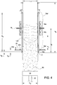
- open bottom electric induction cold crucible 100 comprises a slotted wall formed from a plurality of vertical members 112 separated from each other by vertical slots 114 (shown as solid lines in the figures), with two separate induction coils 116a and 116b surrounding a partial exterior height of the crucible.
- the vertical slotted members are formed from a suitable material such as copper in this example, and may be connected at the top and bottom of the crucible.
- connection between slotted members at the top of the crucible is almost always used and often provides the connection between each member and a water cooling circuit.
- the top connection is normally a significant distance from the melt and hence does not materially affect the induction coupling to the load of material in the crucible.
- the bottom connection is not always used for smaller size crucibles but is more commonly used for larger crucibles where the connection provides support to the bottom of each vertical slotted member.
- the crucible slots are at least sufficiently long to support the inductive heating of the melt within the crucible and facilitate gradual cooling of the ingot as it is created at the solidification boundary 120 (as diagrammatically illustrated in FIG. 1(c) ) until it exits the bottom of the crucible.
- Each of the coils may be connected to a separate alternating current (AC) power source operating at a different frequency.
- AC alternating current
- upper coil 116a may be operating at a frequency that is less than the frequency of the lower coil 116b.
- Flow of alternating current in each coil establishes a magnetic flux field that penetrates the slots (filled with an electrical insulating material) of the crucible to electromagnetically heat and melt an electrically conductive material placed within the interior crucible volume.
- the plurality of vertically members 112 making up the crucible's wall are cooled (typically by internally circulated water) so that the molten mass in contact with the wall freezes. This prevents contamination of the molten mass with wall material.
- the upper regions of the molten mass are at least partially supported by the Lorentz forces generated by the interaction of the magnetic field produced by the induction coils and the induced currents in the melt, to form a region of reduced contact pressure, or even separation, between the wall and the liquid mass of metal.
- the advantage of multiple coils operating at different frequencies is the ability to lower the magnitude of the terminal voltage across each induction coil while still achieving a high level of induced energy transfer to the material within the crucible.
- This is of particular advantage when the electromagnetic casting process is performed with an oxidation prevention cover agent within the interior of the crucible that prevents oxidation of the molten material, as is the case in some silicon electromagnetic casting processes.
- Lower terminal voltages mitigate an arcing phenomenon between the melt and wall in the separation region mentioned above that can result in localized melting of the vertical members making up the crucible wall and migration of impurities from theses vertical members into the molten material within the crucible. The higher the terminal voltage across each coil the greater the risk of an arc.
- the height of the open bottom electric induction cold crucible extends a distance, h 1 , below the lower end of lower induction coil 116b.
- the vertical members 112 making up the wall of the crucible are sloped (tapered) outwards towards the open bottom of the crucible to facilitate movement of the formed ingot out of the crucible.
- the outward tapering may begin between the adjacent terminations of the upper and lower induction coils, to establish a taper distance of h 2 .
- an inter-coil magnetic shield 118 can be positioned between the adjacent ends of coils 116a and 116b to prevent mutual magnetic coupling (and interference) between the magnetic flux established by current flow in each of the two coils.
- Typical resulting magnetic flux patterns are represented by dashed lines in FIG. 1(a) .
- Magnetic flux 116a' is established by alternating current flow through upper coil 116a and magnetic flux 116b' is established by alternating current flow through lower coil 116b.
- Magnetic flux field 116b' extends below the bottom opening of the crucible.
- the portion of the electromagnetic induction field which encompasses the bottom copper connecting member (horizontal) 117 of the crucible induces a circulating current which causes local heating of the surface of the load due to the fact that at the relatively high temperature the solid silicon is still partially conductive. This can cause a local change in the solidification temperature gradient which will increase stresses in the load and may increase the risk of run-outs (which would end the process and damage the equipment).
- FIG. 1(d) illustrates the anomalies by a partial cross sectional thermal diagram near the bottom of the crucible.
- the dashed lines represent boundaries (contours) for typical temperature ranges in a silicon ingot being cast.
- the indicated range of numbers for example, "20-19 kiloWatts (kW) per cubic meter (m 3 )" indicates a range of 20 to 19 kiloWatts per cubic meter of (volumetric) ohmic losses within the representative cross sectional contour in the silicon ingot being cast. Magnitude of ohmic losses within a region is representative of the temperature in the region.
- the invention is apparatus for, and method of, induction heating and melting of a material in an open bottom electric induction cold crucible used in an electromagnetic casting process.
- the open bottom electric induction cold crucible includes a bottom magnetic shield in the vicinity of the lower ends of the slots in the wall, the bottom copper connecting member (horizontal) of the crucible, and the open bottom of the crucible.
- the invention is an open bottom electric induction cold crucible for electromagnetic casting.
- the crucible has a crucible volume into which a charge can be fed for electric induction heating and melting.
- the melt at least partially solidifies within the crucible volume to form an ingot that exits from the open bottom of the crucible.
- the crucible volume is formed from an electrically conductive, water-cooled and slot-segmented wall.
- the slot-segmented wall interfaces with a non-slotted perimeter wall region at the open bottom of the cold crucible and one or more induction coils surround a portion of the exterior height of the crucible volume to inductively heat and melt the charge in the crucible volume.
- a bottom electrically conductive magnetic shield is disposed around the outer perimeter of the slot-segmented wall in a crucible bottom region adjacent to the continuous, electrically conductive and non-slotted perimeter wall region.
- the present invention is a method of electromagnetic casting an ingot in an open bottom electric induction cold crucible.
- a charge of pre-ingot material is supplied to a crucible volume formed from an electrically conductive, water-cooled and slot-segmented wall having a continuous, electrically conductive and non-slotted perimeter wall region at the open bottom of the open bottom electric induction cold crucible.
- a magnetic flux field is generated exterior to the slot-segmented wall around a portion of the height of the slot-segmented wall. The magnetic flux field penetrates into the crucible volume to inductively heat and melt the charge of pre-ingot material within the crucible volume to form a molten pre-ingot composition within the crucible volume.
- the molten pre-ingot composition is at least partially solidified within the crucible volume to form the ingot at the open bottom of the open bottom electric induction cold crucible.
- the magnetic flux field is suppressed from penetrating into the slot-segmented wall adjacent to the non-slotted perimeter wall region.
- electrically conductive material includes materials that are not necessarily electrically conductive in the solid state, but are electrically conductive in the molten state, such as silicon based compositions with varying degrees of purities.
- FIG. 2 through FIG. 4 there is shown in FIG. 2 through FIG. 4 one example of an open bottom electric induction cold crucible 10 of the present invention for use in an electromagnetic casting process.
- a two-coil arrangement is used.
- the open bottom electric induction cold crucible has an overall height, h 3 , of 37-1/8 inches and comprises 60 water-cooled vertical members 12 (slotted wall segments) arranged to form a square-shaped interior volume with a top side length, L 1 , of 13-3/4 inches; a tapered bottom side length, L 2 , of 14 inches; and a tapered height, h 2 , of 13-1/2 inches beginning at inter-coil magnetic shield 18 and extending to the bottom of the crucible as shown in FIG. 3 .
- Overall height, h 4 , of the electrically insulated slots 14 is 26-3/4 inches with the bottoms of the slots terminating at a distance, h 5 , of 1 inch from the bottom of the crucible as shown in FIG. 3 .
- the bottoms 14a the slots terminate at the bottom connecting member 17.
- the slot-segmented wall and bottom connecting member are formed from a suitable electrically conductive material.
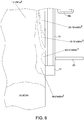
- Bottom magnetic shield 20 in this example of the invention comprises a copper rectangularly-shaped flattened annulus having a side length, L 3 , of 16-3/4 inches ; an annulus width, L 4 , of 6 inches ; and a thickness, L 5 , of 1/4 inches as shown in FIG. 5(a) and FIG. 5(b) .
- the bottom magnetic shield is installed at a height, h 6 , of 2-1/2 inches from the bottom of the crucible so that the bottom magnetic shield is positioned approximately 1-1/2 inches above the bottom slot termination with the bottom connecting member. That is, it is disposed around the outer perimeter of the slot-segmented wall in a crucible bottom region adjacent to the bottom connection member that can also be described as a continuous, electrically conductive and non-slotted perimeter wall region.
- the bottom magnetic shield described above is one example of a suitable magnetic shield.
- the bottom magnetic shield can be formed in any configuration that will conduct an induced current in a location outside the crucible such that the bottom copper connecting member (horizontal) is not subjected to the induction field and hence does not conduct a current in close proximity to the load thus mitigating the adverse heating effects which would otherwise occur.
- the bottom magnetic shield suppresses the magnetic flux field 16b' from penetration into the slotted wall adjacent to the continuous, electrically conductive and non-slotted perimeter wall region (bottom connection member 17).
- the bottom magnetic shield may be cooled, for example, by circulating a cooling medium through passages either within or attached to the bottom magnetic shield, such as conduit 22 with suitable supply and return terminations 22a and 22b for connection to the cooling medium circulation apparatus.
- crucible 10 of the present invention is in a silicon electromagnetic casting process where the crucible is installed in an optional sealable electromagnetic casting furnace vessel operating in an inert atmosphere.
- Induction coils 16a and 16b are installed externally around the crucible volume with inter-coil magnetic shield 18 positioned between the coils inside of the sealed furnace vessel, with the two coils arranged in a stacked (adjacent) configuration around a portion of the height of the crucible.
- a suitable charge supply apparatus can be used to feed solid silicon charge into the open top of the crucible within the sealed vessel.
- the non-electrically conductive solid charge can be initially heated and melted by auxiliary heating apparatus and methods as known in the art until sufficient electrically conductive molten silicon is formed within the crucible so that alternating current flow through the induction coils can further inductively heat the melt and additional solid charge can be supplied to the melt as the length of ingot 90 exiting the crucible grows.
- a temperature control apparatus can be utilized at the bottom exit of the crucible (either within or external to the sealed furnace vessel) to control the temperature of the ingot as it further solidifies.
- Ingot 90 is supported on ingot support member 30 as it is drawn from the crucible and sealed furnace vessel.
- Support member 30 may be formed from graphite and used as a heating element in the heating and melting of the initial solid silicon charge in the furnace.
- Vertical retracting apparatus 32 is attached to the bottom of support member 30 to control the vertical drop rate of the ingot from the bottom of the crucible.
- induced energy to the melt can be provided by increasing the induced power output from the upper induction coil 16a up to approximately 750 kW at 15 kHz by applying a voltage across the terminals of the upper coil. Subsequently, or in combination therewith, further induced energy to the melt can be provided by increasing the induced power output from the lower induction coil 16b up to approximately 300 kW at 35 kHz by applying a voltage across the terminals of the lower coil.
- the applied terminal voltage to the upper induction coil 16a was approximately 600 volts maximum and the applied terminal voltage to the lower induction coil 16b was approximately 600 volts maximum to achieve the above mentioned inductive energy outputs, thus limiting the terminal voltages to approximately less than 600 volts, respectively, to avoid the melt contamination problem mentioned above.
- FIG. 6 illustrates the typical advantage of the present invention in a partial cross sectional thermal diagram near the bottom of the crucible. Comparing FIG. 6 with a bottom magnetic shield 20 placed outside the crucible as in the present invention with FIG. 1(d) where a bottom magnetic shield is not used, at the same current in the coil(s) as that for the example for FIG. 1(d) , the bottom connecting member (horizontal) 17 is shielded from the effect of the induction field and the dashed line contours show that the adverse heating effects are mitigated by use of the bottom magnetic shield in the present invention.
- the above silicon electromagnetic casting process of the present invention can be used with compositions other than silicon with suitable selection of a pre-ingot charge material resulting in a molten pre-ingot composition from which the ingot is formed.
- the invention may be applied to crucibles with a single coil or other than two multiple coils surrounding the exterior of the crucible by locating the bottom magnetic shield relative to the location of the lowest coil, the lower ends of the slots 14a and the bottom opening as described above for the two-coil arrangement.
- continuous electromagnetic casting process includes intermittent electromagnetic casting where, for example, the casting process stops after a manufactured ingot of a desired height exits the bottom of the crucible so that the manufactured ingot can be relocated before the casting process continues to produce another ingot.
Applications Claiming Priority (2)
| Application Number | Priority Date | Filing Date | Title |
|---|---|---|---|
| US201161452408P | 2011-03-14 | 2011-03-14 | |
| PCT/US2012/028064 WO2012125367A2 (en) | 2011-03-14 | 2012-03-07 | Open bottom electric induction cold crucible for use in electromagnetic casting of ingots |
Publications (3)
| Publication Number | Publication Date |
|---|---|
| EP2686122A2 EP2686122A2 (en) | 2014-01-22 |
| EP2686122A4 EP2686122A4 (en) | 2014-11-19 |
| EP2686122B1 true EP2686122B1 (en) | 2018-11-28 |
Family
ID=46828419
Family Applications (1)
| Application Number | Title | Priority Date | Filing Date |
|---|---|---|---|
| EP12757811.0A Active EP2686122B1 (en) | 2011-03-14 | 2012-03-07 | Open bottom electric induction cold crucible for use in electromagnetic casting of ingots and method of casting in the crucible |
Country Status (9)
| Country | Link |
|---|---|
| US (1) | US9476645B2 (ja) |
| EP (1) | EP2686122B1 (ja) |
| JP (1) | JP6016818B2 (ja) |
| KR (1) | KR101956914B1 (ja) |
| CN (1) | CN103442825B (ja) |
| AU (1) | AU2012229371B2 (ja) |
| ES (1) | ES2704883T3 (ja) |
| TW (1) | TWI572839B (ja) |
| WO (1) | WO2012125367A2 (ja) |
Families Citing this family (9)
| Publication number | Priority date | Publication date | Assignee | Title |
|---|---|---|---|---|
| JP2012036056A (ja) * | 2010-08-11 | 2012-02-23 | Sumco Corp | シリコンの電磁鋳造装置 |
| FR3044748B1 (fr) * | 2015-12-03 | 2019-07-19 | Commissariat A L'energie Atomique Et Aux Energies Alternatives | Four a creuset froid a chauffage par deux inducteurs electromagnetiques, utilisation du four pour la fusion d'un melange de metal(ux) et d'oxyde(s) representatif d'un corium |
| KR20200052976A (ko) * | 2017-10-05 | 2020-05-15 | 램 리써치 코포레이션 | 실리콘 튜브들을 생성하기 위한 퍼니스들 (furnace) 및 몰드들 (mold) 을 포함하는 전자기 주조 시스템들 |
| US10711367B2 (en) | 2017-10-30 | 2020-07-14 | Raytheon Technoiogies Corporation | Multi-layer susceptor design for magnetic flux shielding in directional solidification furnaces |
| US10337121B2 (en) * | 2017-10-30 | 2019-07-02 | United Technologies Corporation | Separate vessel metal shielding method for magnetic flux in directional solidification furnace |
| US10760179B2 (en) | 2017-10-30 | 2020-09-01 | Raytheon Technologies Corporation | Method for magnetic flux compensation in a directional solidification furnace utilizing a stationary secondary coil |
| US10589351B2 (en) | 2017-10-30 | 2020-03-17 | United Technologies Corporation | Method for magnetic flux compensation in a directional solidification furnace utilizing an actuated secondary coil |
| WO2020084563A1 (en) * | 2018-10-26 | 2020-04-30 | Lpe S.P.A. | Deposition reactor with inductors and electromagnetic shields |
| AT521904B1 (de) * | 2018-12-11 | 2022-07-15 | Engel Austria Gmbh | Formgebungsmaschine |
Family Cites Families (30)
| Publication number | Priority date | Publication date | Assignee | Title |
|---|---|---|---|---|
| US3598168A (en) * | 1968-10-14 | 1971-08-10 | Trw Inc | Titanium casting process |
| FR2315344A1 (fr) * | 1975-06-27 | 1977-01-21 | Siderurgie Fse Inst Rech | Lingotiere de coulee continue electrorotative |
| US4572812A (en) * | 1984-08-13 | 1986-02-25 | The United States Of America As Represented By The Secretary Of Energy | Method and apparatus for casting conductive and semiconductive materials |
| US4600426A (en) * | 1984-10-01 | 1986-07-15 | Ppg Industries, Inc. | Metering device for molten glass and the like |
| FR2609655B1 (fr) * | 1987-01-15 | 1989-03-24 | Cezus Co Europ Zirconium | Dispositif de fusion et coulee continue de metaux, son procede de mise en oeuvre et son utilisation |
| JP3287031B2 (ja) * | 1991-10-16 | 2002-05-27 | 神鋼電機株式会社 | コールドウォール誘導溶解ルツボ炉 |
| JP2991560B2 (ja) * | 1992-02-24 | 1999-12-20 | 株式会社神戸製鋼所 | 電磁界鋳造鋳型 |
| JP3125586B2 (ja) * | 1994-07-20 | 2001-01-22 | 株式会社神戸製鋼所 | 電磁コイルを用いた連続鋳造方法 |
| JP3122321B2 (ja) * | 1994-11-29 | 2001-01-09 | 神鋼電機株式会社 | 磁束遮断装置を有する誘導加熱による連続鋳造装置と溶解炉 |
| JP3552421B2 (ja) * | 1996-09-26 | 2004-08-11 | Jfeスチール株式会社 | 電磁力を応用した溶融金属の連続鋳造方法およびその装置 |
| JP3552420B2 (ja) * | 1996-09-26 | 2004-08-11 | Jfeスチール株式会社 | 電磁力を応用した溶融金属の連続鋳造方法およびその装置 |
| JPH1099944A (ja) * | 1996-09-30 | 1998-04-21 | Mitsubishi Steel Mfg Co Ltd | 溶融金属の連続鋳造用鋳型構造 |
| CN1092466C (zh) * | 1997-08-10 | 2002-10-09 | 大连理工大学 | 电磁铸造用复合电磁感应器 |
| JP2000264775A (ja) * | 1999-03-23 | 2000-09-26 | Sumitomo Sitix Amagasaki:Kk | 電磁誘導鋳造装置 |
| CN1133519C (zh) * | 2001-01-06 | 2004-01-07 | 大连理工大学 | 一种施加双频电磁场改善连铸坯质量的方法 |
| US6436336B1 (en) * | 2001-06-27 | 2002-08-20 | General Electric Company | Replaceable drain electroslag guide |
| CN2551373Y (zh) | 2002-06-28 | 2003-05-21 | 宝山钢铁股份有限公司 | 软接触电磁连铸结晶器 |
| JP4278423B2 (ja) * | 2003-04-24 | 2009-06-17 | 新日本製鐵株式会社 | 溶融金属の連続鋳造装置 |
| CN1276811C (zh) * | 2004-07-28 | 2006-09-27 | 东北大学 | 水缝-分瓣体内水冷式软接触电磁连铸结晶器 |
| KR100564770B1 (ko) | 2004-08-18 | 2006-03-27 | 한국생산기술연구원 | 고 용해효율 전자기 연속주조장치 |
| WO2007122736A1 (ja) * | 2006-04-25 | 2007-11-01 | Ebis Corporation | 鋳造方法及び装置 |
| JP2008156166A (ja) * | 2006-12-25 | 2008-07-10 | Sumco Solar Corp | シリコンインゴットの鋳造方法および切断方法 |
| JP4640349B2 (ja) * | 2007-02-05 | 2011-03-02 | シンフォニアテクノロジー株式会社 | 連続鋳造装置および連続鋳造装置における鋳造方法 |
| JP2008194700A (ja) * | 2007-02-08 | 2008-08-28 | Shinko Electric Co Ltd | 連続鋳造装置、連続鋳造装置における引抜制御装置、および連続鋳造装置における引抜制御方法 |
| JP5073531B2 (ja) * | 2007-04-10 | 2012-11-14 | 新日本製鐵株式会社 | スラブの連続鋳造装置及びその連続鋳造方法 |
| CN201106071Y (zh) * | 2007-09-20 | 2008-08-27 | 西安理工大学 | 单晶炉勾形电磁场装置 |
| WO2009064731A2 (en) * | 2007-11-17 | 2009-05-22 | Inductotherm Corp. | Melting and mixing of materials in a crucible by electric induction heel process |
| JP2010017749A (ja) * | 2008-07-11 | 2010-01-28 | Sinfonia Technology Co Ltd | 溶解炉、連続鋳造装置、および連続鋳造装置における鋳造方法 |
| CN101829767B (zh) | 2010-05-26 | 2013-10-09 | 丽达科技有限公司 | 硅电磁铸造装置 |
| CN102371348B (zh) * | 2010-08-26 | 2013-04-03 | 宝山钢铁股份有限公司 | 电磁软接触连铸结晶器 |
-
2012
- 2012-03-07 US US13/414,231 patent/US9476645B2/en active Active
- 2012-03-07 KR KR1020137026991A patent/KR101956914B1/ko active IP Right Grant
- 2012-03-07 CN CN201280013618.0A patent/CN103442825B/zh active Active
- 2012-03-07 EP EP12757811.0A patent/EP2686122B1/en active Active
- 2012-03-07 AU AU2012229371A patent/AU2012229371B2/en active Active
- 2012-03-07 ES ES12757811T patent/ES2704883T3/es active Active
- 2012-03-07 JP JP2013558053A patent/JP6016818B2/ja active Active
- 2012-03-07 WO PCT/US2012/028064 patent/WO2012125367A2/en active Application Filing
- 2012-03-14 TW TW101108727A patent/TWI572839B/zh active
Non-Patent Citations (1)
| Title |
|---|
| None * |
Also Published As
| Publication number | Publication date |
|---|---|
| EP2686122A2 (en) | 2014-01-22 |
| US9476645B2 (en) | 2016-10-25 |
| WO2012125367A2 (en) | 2012-09-20 |
| CN103442825B (zh) | 2017-01-18 |
| WO2012125367A3 (en) | 2013-01-03 |
| US20120236898A1 (en) | 2012-09-20 |
| ES2704883T3 (es) | 2019-03-20 |
| CN103442825A (zh) | 2013-12-11 |
| EP2686122A4 (en) | 2014-11-19 |
| KR101956914B1 (ko) | 2019-03-12 |
| AU2012229371A1 (en) | 2013-05-09 |
| TWI572839B (zh) | 2017-03-01 |
| JP2014510641A (ja) | 2014-05-01 |
| TW201243261A (en) | 2012-11-01 |
| KR20140010442A (ko) | 2014-01-24 |
| JP6016818B2 (ja) | 2016-10-26 |
| AU2012229371B2 (en) | 2016-06-09 |
Similar Documents
| Publication | Publication Date | Title |
|---|---|---|
| EP2686122B1 (en) | Open bottom electric induction cold crucible for use in electromagnetic casting of ingots and method of casting in the crucible | |
| EP2363673B1 (en) | Cold crucible induction furnace with eddy current damping | |
| US5109389A (en) | Apparatus for generating an inductive heating field which interacts with metallic stock in a crucible | |
| US8242420B2 (en) | Directional solidification of silicon by electric induction susceptor heating in a controlled environment | |
| US20030205358A1 (en) | Electromagnetic induction casting apparatus | |
| JPS63192543A (ja) | 金属の連続鋳造装置及び該装置の操作方法 | |
| CN102834553B (zh) | 用于生产半导体材料箔的装置和方法 | |
| JP4664967B2 (ja) | シリコン鋳造装置およびシリコン基板の製造方法 | |
| JPH10197694A (ja) | コールドクルーシブル誘導溶融炉からの溶融物抜き出し装置 | |
| JP2007522425A (ja) | 冷るつぼ誘導炉 | |
| JPH05280871A (ja) | 誘導溶解用水冷分割銅るつぼ | |
| TWI527942B (zh) | Silicon electromagnetic casting device | |
| JPH01264920A (ja) | シリコン鋳造装置 | |
| US3729307A (en) | Method and apparatus for electroslag remelting of metals,particularly steel | |
| RU2735329C1 (ru) | Способ левитационной плавки с использованием кольцеобразного элемента | |
| JP2022546446A (ja) | 追加の共振回路を備える誘導炉 | |
| JP4892785B2 (ja) | 誘導加熱溶解炉 | |
| KR20120126913A (ko) | 실리콘 잉곳을 생산하는 전자기 연속 주조 장치 |
Legal Events
| Date | Code | Title | Description |
|---|---|---|---|
| PUAI | Public reference made under article 153(3) epc to a published international application that has entered the european phase |
Free format text: ORIGINAL CODE: 0009012 |
|
| 17P | Request for examination filed |
Effective date: 20131008 |
|
| AK | Designated contracting states |
Kind code of ref document: A2 Designated state(s): AL AT BE BG CH CY CZ DE DK EE ES FI FR GB GR HR HU IE IS IT LI LT LU LV MC MK MT NL NO PL PT RO RS SE SI SK SM TR |
|
| DAX | Request for extension of the european patent (deleted) | ||
| A4 | Supplementary search report drawn up and despatched |
Effective date: 20141022 |
|
| RIC1 | Information provided on ipc code assigned before grant |
Ipc: B22D 11/00 20060101ALI20141016BHEP Ipc: B22D 7/12 20060101AFI20141016BHEP Ipc: B22D 27/02 20060101ALI20141016BHEP Ipc: F27B 14/14 20060101ALI20141016BHEP Ipc: B22D 41/005 20060101ALI20141016BHEP |
|
| REG | Reference to a national code |
Ref country code: DE Ref legal event code: R079 Ref document number: 602012054084 Country of ref document: DE Free format text: PREVIOUS MAIN CLASS: B22D0007120000 Ipc: B22D0011115000 |
|
| GRAP | Despatch of communication of intention to grant a patent |
Free format text: ORIGINAL CODE: EPIDOSNIGR1 |
|
| STAA | Information on the status of an ep patent application or granted ep patent |
Free format text: STATUS: GRANT OF PATENT IS INTENDED |
|
| RIC1 | Information provided on ipc code assigned before grant |
Ipc: B22D 7/12 20060101ALI20180619BHEP Ipc: B22D 11/00 20060101ALI20180619BHEP Ipc: F27B 14/14 20060101ALI20180619BHEP Ipc: F27B 14/10 20060101ALI20180619BHEP Ipc: B22D 11/115 20060101AFI20180619BHEP Ipc: C30B 29/06 20060101ALI20180619BHEP Ipc: B22D 23/06 20060101ALI20180619BHEP Ipc: B22D 11/14 20060101ALI20180619BHEP Ipc: B22D 27/02 20060101ALI20180619BHEP Ipc: C30B 11/00 20060101ALI20180619BHEP Ipc: F27B 14/06 20060101ALI20180619BHEP Ipc: B22D 41/005 20060101ALI20180619BHEP |
|
| INTG | Intention to grant announced |
Effective date: 20180717 |
|
| GRAS | Grant fee paid |
Free format text: ORIGINAL CODE: EPIDOSNIGR3 |
|
| GRAA | (expected) grant |
Free format text: ORIGINAL CODE: 0009210 |
|
| STAA | Information on the status of an ep patent application or granted ep patent |
Free format text: STATUS: THE PATENT HAS BEEN GRANTED |
|
| AK | Designated contracting states |
Kind code of ref document: B1 Designated state(s): AL AT BE BG CH CY CZ DE DK EE ES FI FR GB GR HR HU IE IS IT LI LT LU LV MC MK MT NL NO PL PT RO RS SE SI SK SM TR |
|
| REG | Reference to a national code |
Ref country code: GB Ref legal event code: FG4D |
|
| REG | Reference to a national code |
Ref country code: CH Ref legal event code: EP |
|
| REG | Reference to a national code |
Ref country code: AT Ref legal event code: REF Ref document number: 1069640 Country of ref document: AT Kind code of ref document: T Effective date: 20181215 |
|
| REG | Reference to a national code |
Ref country code: DE Ref legal event code: R096 Ref document number: 602012054084 Country of ref document: DE |
|
| REG | Reference to a national code |
Ref country code: IE Ref legal event code: FG4D |
|
| REG | Reference to a national code |
Ref country code: ES Ref legal event code: FG2A Ref document number: 2704883 Country of ref document: ES Kind code of ref document: T3 Effective date: 20190320 |
|
| REG | Reference to a national code |
Ref country code: NL Ref legal event code: MP Effective date: 20181128 |
|
| REG | Reference to a national code |
Ref country code: LT Ref legal event code: MG4D |
|
| REG | Reference to a national code |
Ref country code: AT Ref legal event code: MK05 Ref document number: 1069640 Country of ref document: AT Kind code of ref document: T Effective date: 20181128 |
|
| PG25 | Lapsed in a contracting state [announced via postgrant information from national office to epo] |
Ref country code: FI Free format text: LAPSE BECAUSE OF FAILURE TO SUBMIT A TRANSLATION OF THE DESCRIPTION OR TO PAY THE FEE WITHIN THE PRESCRIBED TIME-LIMIT Effective date: 20181128 Ref country code: IS Free format text: LAPSE BECAUSE OF FAILURE TO SUBMIT A TRANSLATION OF THE DESCRIPTION OR TO PAY THE FEE WITHIN THE PRESCRIBED TIME-LIMIT Effective date: 20190328 Ref country code: NO Free format text: LAPSE BECAUSE OF FAILURE TO SUBMIT A TRANSLATION OF THE DESCRIPTION OR TO PAY THE FEE WITHIN THE PRESCRIBED TIME-LIMIT Effective date: 20190228 Ref country code: LT Free format text: LAPSE BECAUSE OF FAILURE TO SUBMIT A TRANSLATION OF THE DESCRIPTION OR TO PAY THE FEE WITHIN THE PRESCRIBED TIME-LIMIT Effective date: 20181128 Ref country code: HR Free format text: LAPSE BECAUSE OF FAILURE TO SUBMIT A TRANSLATION OF THE DESCRIPTION OR TO PAY THE FEE WITHIN THE PRESCRIBED TIME-LIMIT Effective date: 20181128 Ref country code: BG Free format text: LAPSE BECAUSE OF FAILURE TO SUBMIT A TRANSLATION OF THE DESCRIPTION OR TO PAY THE FEE WITHIN THE PRESCRIBED TIME-LIMIT Effective date: 20190228 Ref country code: AT Free format text: LAPSE BECAUSE OF FAILURE TO SUBMIT A TRANSLATION OF THE DESCRIPTION OR TO PAY THE FEE WITHIN THE PRESCRIBED TIME-LIMIT Effective date: 20181128 Ref country code: LV Free format text: LAPSE BECAUSE OF FAILURE TO SUBMIT A TRANSLATION OF THE DESCRIPTION OR TO PAY THE FEE WITHIN THE PRESCRIBED TIME-LIMIT Effective date: 20181128 |
|
| PG25 | Lapsed in a contracting state [announced via postgrant information from national office to epo] |
Ref country code: PT Free format text: LAPSE BECAUSE OF FAILURE TO SUBMIT A TRANSLATION OF THE DESCRIPTION OR TO PAY THE FEE WITHIN THE PRESCRIBED TIME-LIMIT Effective date: 20190328 Ref country code: AL Free format text: LAPSE BECAUSE OF FAILURE TO SUBMIT A TRANSLATION OF THE DESCRIPTION OR TO PAY THE FEE WITHIN THE PRESCRIBED TIME-LIMIT Effective date: 20181128 Ref country code: GR Free format text: LAPSE BECAUSE OF FAILURE TO SUBMIT A TRANSLATION OF THE DESCRIPTION OR TO PAY THE FEE WITHIN THE PRESCRIBED TIME-LIMIT Effective date: 20190301 Ref country code: RS Free format text: LAPSE BECAUSE OF FAILURE TO SUBMIT A TRANSLATION OF THE DESCRIPTION OR TO PAY THE FEE WITHIN THE PRESCRIBED TIME-LIMIT Effective date: 20181128 Ref country code: SE Free format text: LAPSE BECAUSE OF FAILURE TO SUBMIT A TRANSLATION OF THE DESCRIPTION OR TO PAY THE FEE WITHIN THE PRESCRIBED TIME-LIMIT Effective date: 20181128 |
|
| PG25 | Lapsed in a contracting state [announced via postgrant information from national office to epo] |
Ref country code: NL Free format text: LAPSE BECAUSE OF FAILURE TO SUBMIT A TRANSLATION OF THE DESCRIPTION OR TO PAY THE FEE WITHIN THE PRESCRIBED TIME-LIMIT Effective date: 20181128 |
|
| PG25 | Lapsed in a contracting state [announced via postgrant information from national office to epo] |
Ref country code: IT Free format text: LAPSE BECAUSE OF FAILURE TO SUBMIT A TRANSLATION OF THE DESCRIPTION OR TO PAY THE FEE WITHIN THE PRESCRIBED TIME-LIMIT Effective date: 20181128 Ref country code: CZ Free format text: LAPSE BECAUSE OF FAILURE TO SUBMIT A TRANSLATION OF THE DESCRIPTION OR TO PAY THE FEE WITHIN THE PRESCRIBED TIME-LIMIT Effective date: 20181128 Ref country code: DK Free format text: LAPSE BECAUSE OF FAILURE TO SUBMIT A TRANSLATION OF THE DESCRIPTION OR TO PAY THE FEE WITHIN THE PRESCRIBED TIME-LIMIT Effective date: 20181128 Ref country code: PL Free format text: LAPSE BECAUSE OF FAILURE TO SUBMIT A TRANSLATION OF THE DESCRIPTION OR TO PAY THE FEE WITHIN THE PRESCRIBED TIME-LIMIT Effective date: 20181128 |
|
| REG | Reference to a national code |
Ref country code: DE Ref legal event code: R097 Ref document number: 602012054084 Country of ref document: DE |
|
| PG25 | Lapsed in a contracting state [announced via postgrant information from national office to epo] |
Ref country code: SK Free format text: LAPSE BECAUSE OF FAILURE TO SUBMIT A TRANSLATION OF THE DESCRIPTION OR TO PAY THE FEE WITHIN THE PRESCRIBED TIME-LIMIT Effective date: 20181128 Ref country code: RO Free format text: LAPSE BECAUSE OF FAILURE TO SUBMIT A TRANSLATION OF THE DESCRIPTION OR TO PAY THE FEE WITHIN THE PRESCRIBED TIME-LIMIT Effective date: 20181128 Ref country code: EE Free format text: LAPSE BECAUSE OF FAILURE TO SUBMIT A TRANSLATION OF THE DESCRIPTION OR TO PAY THE FEE WITHIN THE PRESCRIBED TIME-LIMIT Effective date: 20181128 Ref country code: SM Free format text: LAPSE BECAUSE OF FAILURE TO SUBMIT A TRANSLATION OF THE DESCRIPTION OR TO PAY THE FEE WITHIN THE PRESCRIBED TIME-LIMIT Effective date: 20181128 |
|
| PLBE | No opposition filed within time limit |
Free format text: ORIGINAL CODE: 0009261 |
|
| STAA | Information on the status of an ep patent application or granted ep patent |
Free format text: STATUS: NO OPPOSITION FILED WITHIN TIME LIMIT |
|
| PG25 | Lapsed in a contracting state [announced via postgrant information from national office to epo] |
Ref country code: SI Free format text: LAPSE BECAUSE OF FAILURE TO SUBMIT A TRANSLATION OF THE DESCRIPTION OR TO PAY THE FEE WITHIN THE PRESCRIBED TIME-LIMIT Effective date: 20181128 Ref country code: MC Free format text: LAPSE BECAUSE OF FAILURE TO SUBMIT A TRANSLATION OF THE DESCRIPTION OR TO PAY THE FEE WITHIN THE PRESCRIBED TIME-LIMIT Effective date: 20181128 |
|
| REG | Reference to a national code |
Ref country code: CH Ref legal event code: PL |
|
| 26N | No opposition filed |
Effective date: 20190829 |
|
| REG | Reference to a national code |
Ref country code: BE Ref legal event code: MM Effective date: 20190331 |
|
| PG25 | Lapsed in a contracting state [announced via postgrant information from national office to epo] |
Ref country code: IE Free format text: LAPSE BECAUSE OF NON-PAYMENT OF DUE FEES Effective date: 20190307 Ref country code: CH Free format text: LAPSE BECAUSE OF NON-PAYMENT OF DUE FEES Effective date: 20190331 Ref country code: LI Free format text: LAPSE BECAUSE OF NON-PAYMENT OF DUE FEES Effective date: 20190331 |
|
| PG25 | Lapsed in a contracting state [announced via postgrant information from national office to epo] |
Ref country code: BE Free format text: LAPSE BECAUSE OF NON-PAYMENT OF DUE FEES Effective date: 20190331 |
|
| PG25 | Lapsed in a contracting state [announced via postgrant information from national office to epo] |
Ref country code: TR Free format text: LAPSE BECAUSE OF FAILURE TO SUBMIT A TRANSLATION OF THE DESCRIPTION OR TO PAY THE FEE WITHIN THE PRESCRIBED TIME-LIMIT Effective date: 20181128 |
|
| PG25 | Lapsed in a contracting state [announced via postgrant information from national office to epo] |
Ref country code: MT Free format text: LAPSE BECAUSE OF NON-PAYMENT OF DUE FEES Effective date: 20190307 |
|
| PG25 | Lapsed in a contracting state [announced via postgrant information from national office to epo] |
Ref country code: CY Free format text: LAPSE BECAUSE OF FAILURE TO SUBMIT A TRANSLATION OF THE DESCRIPTION OR TO PAY THE FEE WITHIN THE PRESCRIBED TIME-LIMIT Effective date: 20181128 |
|
| PG25 | Lapsed in a contracting state [announced via postgrant information from national office to epo] |
Ref country code: HU Free format text: LAPSE BECAUSE OF FAILURE TO SUBMIT A TRANSLATION OF THE DESCRIPTION OR TO PAY THE FEE WITHIN THE PRESCRIBED TIME-LIMIT; INVALID AB INITIO Effective date: 20120307 |
|
| PG25 | Lapsed in a contracting state [announced via postgrant information from national office to epo] |
Ref country code: MK Free format text: LAPSE BECAUSE OF FAILURE TO SUBMIT A TRANSLATION OF THE DESCRIPTION OR TO PAY THE FEE WITHIN THE PRESCRIBED TIME-LIMIT Effective date: 20181128 |
|
| PGFP | Annual fee paid to national office [announced via postgrant information from national office to epo] |
Ref country code: LU Payment date: 20230227 Year of fee payment: 12 Ref country code: FR Payment date: 20230208 Year of fee payment: 12 |
|
| PGFP | Annual fee paid to national office [announced via postgrant information from national office to epo] |
Ref country code: ES Payment date: 20230405 Year of fee payment: 12 |
|
| PGFP | Annual fee paid to national office [announced via postgrant information from national office to epo] |
Ref country code: LU Payment date: 20240227 Year of fee payment: 13 |
|
| PGFP | Annual fee paid to national office [announced via postgrant information from national office to epo] |
Ref country code: DE Payment date: 20240130 Year of fee payment: 13 Ref country code: GB Payment date: 20240201 Year of fee payment: 13 |