EP2685913B1 - Apparatus for a manual radial artery compression device - Google Patents
Apparatus for a manual radial artery compression device Download PDFInfo
- Publication number
- EP2685913B1 EP2685913B1 EP12712188.7A EP12712188A EP2685913B1 EP 2685913 B1 EP2685913 B1 EP 2685913B1 EP 12712188 A EP12712188 A EP 12712188A EP 2685913 B1 EP2685913 B1 EP 2685913B1
- Authority
- EP
- European Patent Office
- Prior art keywords
- radial artery
- pressure
- bladder
- patient
- pressure bladder
- Prior art date
- Legal status (The legal status is an assumption and is not a legal conclusion. Google has not performed a legal analysis and makes no representation as to the accuracy of the status listed.)
- Active
Links
- 230000006835 compression Effects 0.000 title claims description 86
- 238000007906 compression Methods 0.000 title claims description 86
- 210000002321 radial artery Anatomy 0.000 title claims description 81
- 230000023597 hemostasis Effects 0.000 claims description 48
- 210000000707 wrist Anatomy 0.000 claims description 41
- 239000012530 fluid Substances 0.000 claims description 24
- 230000007246 mechanism Effects 0.000 claims description 15
- 210000001367 artery Anatomy 0.000 claims description 9
- 239000000463 material Substances 0.000 claims description 7
- 229940030225 antihemorrhagics Drugs 0.000 claims description 6
- 239000008280 blood Substances 0.000 claims description 6
- 210000004369 blood Anatomy 0.000 claims description 6
- 239000002874 hemostatic agent Substances 0.000 claims description 5
- 238000004891 communication Methods 0.000 claims description 4
- 238000003825 pressing Methods 0.000 claims description 4
- OVRNDRQMDRJTHS-FMDGEEDCSA-N N-acetyl-beta-D-glucosamine Chemical compound CC(=O)N[C@H]1[C@H](O)O[C@H](CO)[C@@H](O)[C@@H]1O OVRNDRQMDRJTHS-FMDGEEDCSA-N 0.000 claims description 3
- 229950006780 n-acetylglucosamine Drugs 0.000 claims description 3
- 230000004913 activation Effects 0.000 claims 2
- 238000000034 method Methods 0.000 description 30
- 208000032843 Hemorrhage Diseases 0.000 description 10
- 206010052428 Wound Diseases 0.000 description 10
- 230000002792 vascular Effects 0.000 description 10
- 210000000245 forearm Anatomy 0.000 description 9
- 230000000740 bleeding effect Effects 0.000 description 7
- 206010070995 Vascular compression Diseases 0.000 description 6
- 208000027418 Wounds and injury Diseases 0.000 description 6
- 230000000747 cardiac effect Effects 0.000 description 6
- 230000002439 hemostatic effect Effects 0.000 description 6
- 206010018852 Haematoma Diseases 0.000 description 5
- 239000000853 adhesive Substances 0.000 description 5
- 230000001070 adhesive effect Effects 0.000 description 5
- 210000003414 extremity Anatomy 0.000 description 4
- 230000008878 coupling Effects 0.000 description 3
- 238000010168 coupling process Methods 0.000 description 3
- 238000005859 coupling reaction Methods 0.000 description 3
- 210000001105 femoral artery Anatomy 0.000 description 3
- 230000002093 peripheral effect Effects 0.000 description 3
- 210000003813 thumb Anatomy 0.000 description 3
- 229920001661 Chitosan Polymers 0.000 description 2
- 206010014080 Ecchymosis Diseases 0.000 description 2
- 238000002399 angioplasty Methods 0.000 description 2
- 230000008901 benefit Effects 0.000 description 2
- 230000036772 blood pressure Effects 0.000 description 2
- 230000006870 function Effects 0.000 description 2
- 230000003100 immobilizing effect Effects 0.000 description 2
- 238000003780 insertion Methods 0.000 description 2
- 230000037431 insertion Effects 0.000 description 2
- 238000005086 pumping Methods 0.000 description 2
- 210000003857 wrist joint Anatomy 0.000 description 2
- 206010053567 Coagulopathies Diseases 0.000 description 1
- 108090000190 Thrombin Proteins 0.000 description 1
- 239000002390 adhesive tape Substances 0.000 description 1
- 238000013459 approach Methods 0.000 description 1
- 230000002457 bidirectional effect Effects 0.000 description 1
- 230000033228 biological regulation Effects 0.000 description 1
- 210000004204 blood vessel Anatomy 0.000 description 1
- 210000002302 brachial artery Anatomy 0.000 description 1
- 230000003749 cleanliness Effects 0.000 description 1
- 230000035602 clotting Effects 0.000 description 1
- 230000000295 complement effect Effects 0.000 description 1
- 239000002872 contrast media Substances 0.000 description 1
- 230000001276 controlling effect Effects 0.000 description 1
- 210000004351 coronary vessel Anatomy 0.000 description 1
- 230000000994 depressogenic effect Effects 0.000 description 1
- 229940079593 drug Drugs 0.000 description 1
- 239000003814 drug Substances 0.000 description 1
- 230000002526 effect on cardiovascular system Effects 0.000 description 1
- 210000003811 finger Anatomy 0.000 description 1
- 239000006260 foam Substances 0.000 description 1
- 230000000025 haemostatic effect Effects 0.000 description 1
- 239000003589 local anesthetic agent Substances 0.000 description 1
- 229940127554 medical product Drugs 0.000 description 1
- QSHDDOUJBYECFT-UHFFFAOYSA-N mercury Chemical compound [Hg] QSHDDOUJBYECFT-UHFFFAOYSA-N 0.000 description 1
- 229910052753 mercury Inorganic materials 0.000 description 1
- 238000012544 monitoring process Methods 0.000 description 1
- 230000000474 nursing effect Effects 0.000 description 1
- 235000015097 nutrients Nutrition 0.000 description 1
- 208000035824 paresthesia Diseases 0.000 description 1
- 230000001737 promoting effect Effects 0.000 description 1
- 230000009467 reduction Effects 0.000 description 1
- 230000001105 regulatory effect Effects 0.000 description 1
- 230000008439 repair process Effects 0.000 description 1
- 230000033764 rhythmic process Effects 0.000 description 1
- 210000000329 smooth muscle myocyte Anatomy 0.000 description 1
- 238000012360 testing method Methods 0.000 description 1
- 229960004072 thrombin Drugs 0.000 description 1
- 210000001519 tissue Anatomy 0.000 description 1
- 238000012546 transfer Methods 0.000 description 1
- 210000002559 ulnar artery Anatomy 0.000 description 1
- 238000011144 upstream manufacturing Methods 0.000 description 1
- 210000005166 vasculature Anatomy 0.000 description 1
Images


Classifications
-
- A—HUMAN NECESSITIES
- A61—MEDICAL OR VETERINARY SCIENCE; HYGIENE
- A61B—DIAGNOSIS; SURGERY; IDENTIFICATION
- A61B17/00—Surgical instruments, devices or methods, e.g. tourniquets
- A61B17/12—Surgical instruments, devices or methods, e.g. tourniquets for ligaturing or otherwise compressing tubular parts of the body, e.g. blood vessels, umbilical cord
- A61B17/132—Tourniquets
- A61B17/135—Tourniquets inflatable
-
- A—HUMAN NECESSITIES
- A61—MEDICAL OR VETERINARY SCIENCE; HYGIENE
- A61B—DIAGNOSIS; SURGERY; IDENTIFICATION
- A61B17/00—Surgical instruments, devices or methods, e.g. tourniquets
- A61B17/12—Surgical instruments, devices or methods, e.g. tourniquets for ligaturing or otherwise compressing tubular parts of the body, e.g. blood vessels, umbilical cord
- A61B17/132—Tourniquets
- A61B17/1322—Tourniquets comprising a flexible encircling member
- A61B17/1325—Tourniquets comprising a flexible encircling member with means for applying local pressure
-
- A—HUMAN NECESSITIES
- A61—MEDICAL OR VETERINARY SCIENCE; HYGIENE
- A61B—DIAGNOSIS; SURGERY; IDENTIFICATION
- A61B17/00—Surgical instruments, devices or methods, e.g. tourniquets
- A61B2017/00535—Surgical instruments, devices or methods, e.g. tourniquets pneumatically or hydraulically operated
- A61B2017/00557—Surgical instruments, devices or methods, e.g. tourniquets pneumatically or hydraulically operated inflatable
-
- A—HUMAN NECESSITIES
- A61—MEDICAL OR VETERINARY SCIENCE; HYGIENE
- A61F—FILTERS IMPLANTABLE INTO BLOOD VESSELS; PROSTHESES; DEVICES PROVIDING PATENCY TO, OR PREVENTING COLLAPSING OF, TUBULAR STRUCTURES OF THE BODY, e.g. STENTS; ORTHOPAEDIC, NURSING OR CONTRACEPTIVE DEVICES; FOMENTATION; TREATMENT OR PROTECTION OF EYES OR EARS; BANDAGES, DRESSINGS OR ABSORBENT PADS; FIRST-AID KITS
- A61F5/00—Orthopaedic methods or devices for non-surgical treatment of bones or joints; Nursing devices; Anti-rape devices
- A61F5/01—Orthopaedic devices, e.g. splints, casts or braces
- A61F5/02—Orthopaedic corsets
- A61F5/022—Orthopaedic corsets consisting of one or more shells
Definitions
- the present disclosure relates to a radial artery compression device.
- this invention relates to a self-contained manual vascular compression device.
- the present disclosure relates to a radial artery compression device configured to be releasably secured to the wrist of a patient and to provide an adjustable level of compression pressure on the radial artery to achieve hemostasis at, or in the area of, a vascular access site.
- a sheath having a haemostatic valve is utilized to access a peripheral artery utilizing the administration of a local anesthetic at the vascular access site.
- a pre-shaped catheter is then introduced into the patient's vasculature through the sheath.
- the catheter can then be advanced to the ostium of the relevant coronary artery or to another desired location within the patient.
- the catheter enables delivery of medical instruments, medicines or fluids such as radiography contrast medium, angioplasty wires, balloons, and stents.
- the sheath and catheter are removed and hemostasis can be achieved by manual compression, suturing the access site, or by utilizing another direct repair procedure.
- the relatively superficial position of the distal radial artery enables relatively direct application of compression to the artery to achieve and maintain hemostasis during a procedure. Additionally the radial artery allows quick and direct closure at the catheter access site as soon as the arterial catheter has been removed at the end of the procedure.
- the access site, or opening, in the artery is created utilizing a micropuncture apparatus, dilator or can even be formed utilizing a single straight incision to form a slit in the artery.
- the arterial walls include a layer of smooth muscle cells that expand and contract in conjunction with the rhythm of the heart to complement the pumping of the heart and to facilitate movement of blood throughout the body.
- the expanding and contracting of the radial artery may present challenges to achieving hemostasis at the access site.
- blood may leak through the access site and around the outside diameter of the sheath or catheter.
- Existing radial artery compression devices are not adapted to provide desired and/or adjustable compression to the radial artery at the vascular access site during the course of a procedure.
- the catheter When the procedure has been completed, typically the catheter is removed and the practitioner or medical professional will apply pressure at the vascular access site to achieve hemostasis and effectuate closure of the vascular access site.
- One technique for achieving hemostasis is to apply pressure at, or at a point slightly upstream, of the vascular access site. Typically, continuous pressure is necessary to stop bleeding and achieve hemostasis at the access site. While the applied pressure should remain relatively constant, there are advantages to applying a higher level of compression pressure at the beginning of the compression period and then reducing the level of compression pressure after a determined amount of time has elapsed.
- blood can begin to flow through the artery at a reduced pressure, providing nutrient rich blood to the tissue downstream from the access site. Blood flowing through the artery can then hasten clotting to enable hemostasis without application of ongoing compression. Not only can this provide improved closure, but also can improve the relative comfort of the patient.
- Compression is typically applied to an access site by a nurse or other practitioner by manually holding a dressing at the access site.
- a practitioner to provide compression permits the gradual reduction of pressurization at the access site, it can also be a costly use of practitioner time.
- Alternative existing radial artery compression techniques which do not require the ongoing manual application of pressure by the practitioner may employ tape or a compression bandage at the vascular access site. These devices and techniques, while allowing the practitioner to attend to other matters, can render it difficult or impractical to adjust the compression pressure while maintaining continuous pressure. As a result, the tape or compression bandages may end up being positioned around the access site without being loosened or adjusted until they are removed.
- Petersen describes a free standing apparatus which may be attached to the bottom frame of a hospital bed.
- a pressure applying head is mounted on a swing arm attached to the vertical shaft of the base and can be positioned directly above the wound.
- Pressure is developed by either compressed air or an electric motor.
- Two pressure shoes can be positioned to provide both vertical and horizontal pressure.
- Lee discloses a pneumatically operated femoral artery compressor applying calibrated and calibrateable external pressure on the puncture site of the femoral artery with the plunger end of a mounted pressurized assembly.
- Breen et. al describes another type of partly automated solution, which also uses pneumatic pressure, in U.S. Patent No. 5,792,173 .
- Breen describes a wound closure device that includes an inflatable balloon with an inflation and deflation outlet.
- the balloon is coupled to patch, having an aperture for receiving the inflation/deflation outlet.
- the assembly is coupled to the placement patch and is held via a belt strap at either the wound site or on a bleeding vessel.
- McNeese et al (US Pub. No. 2009/0281565 ) describes an even more complicated solution comprising a rotatable knob coupled to a threaded shaft and a pad. The screw can be tightened to provide pressure on the radial artery.
- Roth in U.S. Patent No. 5,263,965 , describes a device that is used to apply direct pressure to arterial and venous incisions to promote hemostasis. It consists of a round flat disk with a user manipulable member used for applying downward pressure. In the preferred embodiment the user manipulable member consists of a peg over which a cylindrical weight is pivotally mounted. A stretchable bandage is used to secure the weight in place.
- This manual compression aid is comprised of a cylindrically shaped handle above a sterile disposable disk. The disk is placed above the catheter insertion point with the catheter inside the notch of the disk. As the catheter is removed, pressure is applied to the handle to force the disk to compress the artery and thereby control bleeding - ultimately achieving hemostasis.
- This type of device has a number of disadvantages including: the cost of the apparatus; the difficulty associated in ensuring a minimal level of cleanliness; and the time associated in connecting the disposable disk to the assembly prior to its use on a patient.
- This manual vascular compression device also includes a handle an elongated shaft and a pad or disk.
- the pad or disk is integral to the assembly and the entire apparatus is disposable.
- the pad is flat and contains a notched or equivalent area for locating the catheter.
- US Patent Publication No. 2003/0114881 discloses a compression device for achieving haemostasis in a puncture wound.
- the device comprises a compressor and a pressure element connected to the compressor so that the bottom side of the pressure element is in contact with the puncture wound.
- the bottom side of the pressure element is provided with chitosan, so that the chitosan and the external compression pressure are applied simultaneously on the puncture wound when the compressor applies an external compression pressure on the puncture wound via the pressure element.
- US Patent No. 7,498,477 discloses a hemostatic device.
- the device includes a flexible band adapted to be wrapped around a patient's limb at a site on the limb where bleeding is to be stopped, a portion for securing the band in a wrapped state to the limb, a curved plate which is made of a material more rigid than the band and at least a portion of which is curved toward the inner peripheral side thereof, a main balloon which is provided on the inner peripheral side of the curved plate and which inflates when a fluid is introduced therein, and a pressing member which is provided between the curved plate and the main balloon so that at least a portion thereof overlaps with the balloon and which is adapted for pressing against the balloon.
- the balloon has connected thereto an inflator for introducing a fluid into the balloon, the inflator composed of a flexible tube which is connected at a proximal end to the balloon, a bulb provided at the distal end of the tube, and a tubular connector which is joined to the bulb.
- Inflation of the balloon is carried out by inserting the protruding tip of a syringe into the connector and pushing a plunger on the syringe so as to introduce fluid within the syringe through the inflator into the balloon.
- a check valve within the connector prevents the fluid from leaking out and thus maintains the balloon in an inflated state.
- the present invention provides a radial artery compression system as claimed in claim 1.
- the radial artery compression system is comprised of a radial artery compression device.
- the radial artery compression device of the invention is configured to be releasably secured by a strap or band to the underside of a wrist of a patient to provide continuous and adjustable compression in the area of a radial artery access site.
- the radial artery access site can be an opening formed utilizing a micropuncture apparatus, a dilator, an incision, or other percutaneous access device or procedure which allows insertion of a sheath and/or a catheter into the radial artery.
- the radial artery compression device can be configured to provide compression pressure in the area of the radial artery access site to achieve hemostasis.
- the radial artery compression device of the present invention is effective for achieving hemostasis at the access site during and after a medical procedure such as a vascular delivery procedure.
- the radial artery compression device includes a body having a pump, a pressure control device and a pressure bladder. As the pump is engaged the pressure bladder is filled with fluid, and the pressure bladder applies pressure through the skin of a subject onto the radial artery.
- the pump comprises a fluid containing bladder, which when depressed or otherwise compressed moves fluid from the pump to the pressure bladder, thereby increasing the pressure on the radial artery.
- the fluid is air.
- the pressure control device regulates the pressure in the pressure bladder.
- the pressure control device can be actuated to release fluid from the pressure bladder thereby reducing the pressure in the pressure bladder.
- the pressure control device is bidirectional and serves to allow fluid, preferably air, into the pump, which the pump then transmits to the pressure bladder.
- the pressure control device is a valve.
- the pump and the pressure bladder are formed as a unitary piece.
- the pump, the pressure bladder and the pressure control device are disposed on a single plane and form a unit.
- the body of the radial artery compression device which comprises the pump, the pressure bladder and the pressure control device is such that the entire unit may be disposed on a patient's arm or wrist and no portion of the device extends past the boundaries of the patients limb.
- the radial artery compression device further comprises securing means, which may be a band coupled to the body, configured to secure the body to the underside of a wrist of a patient in the area of the radial artery.
- securing means which may be a band coupled to the body, configured to secure the body to the underside of a wrist of a patient in the area of the radial artery.
- the radial artery compression device can further comprise a covering or sheathing that covers and/or encloses portions of the pump and the pressure bladder.
- the covering is disposed on at least a portion of the top surface of the pressure bladder (i.e. the surface not in contact with the patient) and serves to restrain the pressure bladder from expanding thereby directing the force of the pressure bladder in the direction of the radial artery.
- the radial artery compression system comprises (a) the radial artery compression device including the various embodiments described above; and (b) a brace for immobilizing the wrist of the arm to which the radial artery compression device is attached.
- the brace may be comprised of (a) an elongated rigid member having a proximal and distal end; and (b) a plurality of fasting members disposed at the proximal and distal ends of said member and capable of securing said elongated rigid member to the wearer's forearm.
- the rigid member is curved throughout its length and about its longitudinal axis.
- the brace is positionable on the dorsal aspect of the forearm wrist and hand to support and immobilize the portion of the hand proximal to the wrist, the wrist and the portion of the forearm proximal to the wrist and among other functions prevents rotational movement of the hand around the wrist joint.
- the radial artery compression system of the invention comprises (a) the radial artery compression device including the various embodiments described above; optionally (b) a brace for immobilizing the wrist of the arm to which the radial artery compression device is attached; and (c) a compression pad disposed to be in direct contact with the wound site.
- the compression pad is comprised of a hemostatic agent.
- the hemostatic agent is poly-N-Acetyl Glucosamine.
- a method for compressing a radial artery at an access site of a radial artery of a subject comprises:(a) providing a radial artery compression device comprising, a pump to be actuated by a user by application of pressure to said pump, a pressure bladder capable by being inflated by the pump and pressure regulation means for regulating the pressure exerted by the pressure bladder; (b) positioning the device such that the pressure bladder is in contact with the underside of the patient's wrist near an access site, the access site providing access to the radial artery; (c) attaching the device to the wrist of a patient, with the pressure bladder; and (d) manually actuating the pump and inflating the pressure bladder to a desired pressure.
- One exemplary method further comprises providing a brace, as disclosed above, configured to secure the patient's wrist from rotating or moving; affixing the brace to the dorsal (back) side of patient's wrist.
- the method further comprises providing a compression pad to be disposed between the pressure bladder of the compression device of the invention and the underside of the patient's wrist.
- One exemplary method further comprises a device being inserted into the radial artery via the access site.
- the pressure provided by the pressure bladder is sufficient to cause hemostasis.
- Use of the system of the invention may result in hemostasis in one hour or less, preferably in 30 minutes or less and most preferably in 15 minutes or less. Hemostasis may be achieved within 10 minutes.
- the incidence of any complication associated with use of the system may be less than 10%, preferably less than 5% and most preferably less than 1%.
- the vascular compression apparatus of the invention is used on a patient to apply pressure on an area near or at a wound site, such as a blood vessel puncture, most often after a cannulated procedure such as angioplasty, for the purpose of controlling the patient's bleeding and, further, of achieving hemostasis.
- the device may be used to provide pressure and control hemostasis of the radial artery.
- FIG. 1 shows the manual vascular compression device of the invention 1.
- the device has a body 10 having pump 20, a pressure bladder 30 and a pressure control mechanism 40.
- the pump is in direct fluid connection with the pressure bladder 30.
- the pressure bladder 30 is in direct fluid communication with the pressure control mechanism 40.
- the pressure control mechanism 40 and the pump 20 are not in direct fluid communication with each other and are otherwise only connected through the pressure bladder 30.
- the pressure bladder 30 may take a number of different forms but is generally made out of any flexible and/or pliable material.
- the device is placed on a patient's body on or near the area that requires hemostasis or occlusion.
- the bladder is inflated by means of the pump 20 using a fluid.
- the fluid is a gaseous fluid, most preferably the fluid is air.
- the pressure bladder be inflated to a volume sufficient to provide hemostasis and/or occlude the vessel of interest, without occluding other vessels. This is particularly important in the case of cardiac interventions through the radial artery.
- the pressure bladder is capable of being inflated with about 15-25 cc of fluid and in a preferred embodiment the pressure bladder is capable of inflated to a volume of no more than about 20 cc.
- the device of FIG. 1 also includes securing means 50 for securing the body to a patient's body, for use in providing pressure for hemostasis.
- the device 1 is secured to a patient's wrist for aid in providing pressure to the radial artery.
- the securing means may be a unitary piece or may be two separate pieces akin to a watch band.
- FIG. 2 is a rear perspective view of an embodiment of the subject device and shows further details of the securing means including optional attachment means 90 that can be disposed on the securing means 50 to secure the device 1 to the patient.
- the attachment means may be a portion of hook and loop fastener such as VELCRO®.
- the securing means may comprise adhesives including adhesive table or a system of holes and tines similar to a conventional watch band.
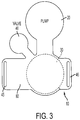
- FIG. 3 is a schematic of the device body 10 and further shows the relationships of the various components to one another.
- FIG. 3 further shows optional coupling means for coupling device body 10 to the securing means 50.
- the coupling means comprises openings 45 and 46 in the device body which allow the securing means 50, which is preferably a flexible band to pass, through and secure and couple the securing means 50 to the device body.
- the securing means is unitary in nature (i.e. a single continues piece) and is disposed through the openings 45 and 46 and over the device body 10.
- FIG. 4 is a schematic of just such a securing means.
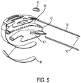
- FIG. 5 shows a partial exploded view of the embodiment of FIG. 1 .
- the view shows an optional restrictor 80, which is disposed between the device body 10 and the securing means 50.
- the restrictor is made of a rigid or semi-rigid material and serves to focus the force of the expanding pressure in a downward direction towards the patient.
- FIG. 5 also shows one embodiment of the pressure regulator 40 comprising a valve 41 and a valve receptacle 42, the valve receptacle being integral to the device body.
- the pump 20 is a commercially available configuration which has been refined for efficient actuation between the thumb and side of pointer finger.
- the pump may optionally include an integral check valve to allow flow into the bladder and a return element to restore the pump to the starting position.
- the return element may take a number of different form including a spring, elastic or other type of device that is capable of providing sufficient force to return the pump to its starting position including but not limited to spring(s), elastics or other devices.
- the return element is made of foam, and provides a force to the pump when the pump is compressed.
- a hole or other opening in the surface of the pump is introduced to allow the pump to refill with air on the return stroke.
- the hole is closed by the thumb during pumping to create pressure and hence flow through the check valve into the bladder.
- the bladder 30 is a generally spherical inflatable chamber which applies pressure between the bridge and the patient's wrist.
- the size of the bladder was developed to allow sufficient stroke to fill the space under the bridge and transfer the internal pressure to the patient incision site.
- the spherical form allows focusing of the applied force at the point of contact at the center of the footprint. The pressure capacity, volume, and reliability requirements of the bladder have not been determined.
- the pressure control mechanism 40 can take a number of different forms. As discussed above, in one embodiment, the pressure control mechanism 40 is comprised of a valve 41 for exhausting the fluid and a valve receptacle 42. In one embodiment, the exhaust valve is a normally closed valve seated by a spring and the closure force is increased when the bladder is pressurized. When actuated via pressing a button on the valve, the valve opens allowing flow which exhausts the pressure in the bladder.
- the pressure bladder 30 is connected to the pressure control mechanism 40 through an exhaust path.
- the exhaust path may optionally contain a flow restrictor in the channel between the bladder and the exhaust valve.
- the flow restrictor may be used to control the exhaust flow rate so the user can reduce the pressure in a gradual and controlled manner.
- the flow restrictor is 0.15 mm (0.006") in internal diameter and 6.35 mm (0.25") long.
- the vascular compression device is generally molded of a mostly flexible material. The only requirement is that the material is sturdy enough to withstand the application of downward pressure onto a human patient, sufficient to cause a complete occlusion of an artery. Generally, the device should be capable of promoting hemostasis at blood pressure of at least about 200mm of mercury, 0.27 bar, or 3.9 PSI. In a preferred embodiment, the device should be capable of generating at least about 0.55 bars (8 PSI) or greater of internal pressure or in other words at least about 2 times the blood pressure.
- the device 1 may be packaged and sterilized as a sterile medical product so that the user needs not clean or wash it prior to its use. In a preferred embodiment the material is transparent so that the user can more easily align the device with the wound.
- the radial artery compression system of the invention comprises: (a) the radial artery compression device defined herein in all of its embodiments; and (b) a brace for restricting the movement and/or rotation of the subject's wrist. Applicants have found that restricting movement of the wrist and associated structures improves the performance of the system and ultimately improves patient outcomes.
- FIG. 6 shows an exemplar embodiment of the brace of the invention.
- the brace 600 has a an elongated rigid member 610 having a proximal end 612 and distal end 611 along which a subject's forearm and hand would be disposed in a "palm up" orientation; the palm being disposed across and along the distal end 611.
- the brace also has a plurality of fastening members 620 to secure the brace to the subject's arm.
- At least one fastening member 631 attaches to a fastener 611 at the distal end of the brace, thereby securing the subject's hand and a second fastening member 622 attaches to a fastener 632, thereby securing the subject's forearm.
- the fastening member 620 are permanently attached on one side of the brace and are fastened to the fasteners 631 and 632 on the opposite side of the brace.
- the brace includes one or more side-walls 630 that are disposed approximately perpendicularly to the elongated rigid member 610 of the brace.
- the optional side walls provide for better placement of the brace as well as further enhance the ability of the brace to restrict movement of the wrist and its associated structures.
- the side wall of the brace may also have a securing region 635 to which the securing means 50 of the vascular compression device 1 may be secured.
- the securing means may be a hook and loop type of fastener such as VELCRO®.
- the rigid member is curved throughout its length and about its longitudinal axis.
- the brace is attached on the dorsal aspect of the forearm, wrist and hand to support and immobilize the portion of the hand proximal to the wrist, the wrist and the portion of the forearm proximal to the wrist and among other functions prevents rotational movement of the hand around the wrist joint.
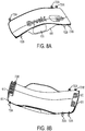
- FIGs. 7A and 7B show an alternative fastening arrangement of the brace 610.
- FIG. 7A shows a pair of fastening members 721 and 722 that are detachable from the brace and can be fastened at various positions through a series of holes.
- FIG. 7B shows the brace 610 having a plurality of fastener pairs (731A and 731B) and (732A and 732B) disposed at the distal end 611 of the brace 610 to which a fastener 721 may be attached.
- a second fastener 722 would be attached to a second pair 733A and 733B of fasteners at the proximal end 612 of the brace 610.
- FIG. 8 shows the embodiment of FIGs. 7A and 7B with the addition of a plurality of moldable flat areas 810 and 820.
- These moldable flat areas which may be incorporated in any embodiment of the invention provide for a location to which adhesive may be applied to better secure the brace to the dorsal side of the forearm.
- the adhesive may be a double-sided adhesive tape, but any suitable adhesive would be appropriate.
- the standard of post procedure care for achieving hemostasis following radial artery diagnostic and interventional cardiac catheterization is typically 2 to 6 hours, using a variety of compression techniques.
- Wrist band (TR Band, Terumo, Japan)
- the Syvek patch is a hemostatic patch comprising poly-N-Acetyl- Glucosamine (p-GlcNAc) as the hemostatic agent.
- the 15 patients were randomly assigned to 10, 30, or 60 minute compression intervals and hemostasis was assessed at each of these intervals. Hemostasis is defined as the ceasing of bleeding with no re-bleeding within 1 hour of the initial hemostasis.
- Plethysmography and oxymetry were recorded and a Barbeau classification was determined for both radial and ulnar artery flow at baseline, immediately after compression release, and 1hr, 4hr, and 1 day post hemostasis depending on the length of patient hospital stay.
- the subject invention not only increases the proportion of patients achieving hemostasis at one hour from 3% to 100% but also was able to achieving hemostasis at 30 minutes (100%) and at 10 minutes (92.3%). Remarkably, the patients treated with subject inventions had no local complications.
Landscapes
- Health & Medical Sciences (AREA)
- Life Sciences & Earth Sciences (AREA)
- Surgery (AREA)
- Engineering & Computer Science (AREA)
- Animal Behavior & Ethology (AREA)
- Vascular Medicine (AREA)
- Nuclear Medicine, Radiotherapy & Molecular Imaging (AREA)
- Veterinary Medicine (AREA)
- Public Health (AREA)
- Biomedical Technology (AREA)
- Heart & Thoracic Surgery (AREA)
- Medical Informatics (AREA)
- Molecular Biology (AREA)
- Reproductive Health (AREA)
- General Health & Medical Sciences (AREA)
- Biophysics (AREA)
- Hematology (AREA)
- Surgical Instruments (AREA)
Applications Claiming Priority (2)
| Application Number | Priority Date | Filing Date | Title |
|---|---|---|---|
| US201161454101P | 2011-03-18 | 2011-03-18 | |
| PCT/US2012/029600 WO2012129146A2 (en) | 2011-03-18 | 2012-03-19 | Methods and apparatus for a manual radial artery compression device |
Publications (2)
| Publication Number | Publication Date |
|---|---|
| EP2685913A2 EP2685913A2 (en) | 2014-01-22 |
| EP2685913B1 true EP2685913B1 (en) | 2018-05-09 |
Family
ID=45929619
Family Applications (1)
| Application Number | Title | Priority Date | Filing Date |
|---|---|---|---|
| EP12712188.7A Active EP2685913B1 (en) | 2011-03-18 | 2012-03-19 | Apparatus for a manual radial artery compression device |
Country Status (8)
| Country | Link |
|---|---|
| US (1) | US9867625B2 (es) |
| EP (1) | EP2685913B1 (es) |
| JP (1) | JP6138702B2 (es) |
| AU (2) | AU2012231150A1 (es) |
| CA (1) | CA2828910C (es) |
| ES (1) | ES2675721T3 (es) |
| MX (1) | MX355118B (es) |
| WO (1) | WO2012129146A2 (es) |
Families Citing this family (27)
| Publication number | Priority date | Publication date | Assignee | Title |
|---|---|---|---|---|
| PL221369B1 (pl) | 2011-10-28 | 2016-03-31 | Inst Kardiologii | Tętnicza opaska uciskowa |
| US20160271004A1 (en) * | 2013-03-20 | 2016-09-22 | Sanko Özel Egitim Hizmetleri A.S. | Feedback electro hemostatic compression pad |
| US9308000B2 (en) * | 2013-07-12 | 2016-04-12 | Vasoinnovations, Inc. | Method of transradial catheterization, device for ulnar artery compression, and method of use |
| US9795391B2 (en) | 2013-10-25 | 2017-10-24 | Medtronic Vascular, Inc. | Tissue compression device with tension limiting strap retainer |
| US10092297B2 (en) | 2014-04-25 | 2018-10-09 | Medtronic Vascular, Inc. | Tissue compression device with fixation and tension straps |
| CN104274226A (zh) * | 2014-09-22 | 2015-01-14 | 张梅 | 一种新型介入治疗术后穿刺部位止血装置 |
| US20180214160A1 (en) * | 2015-01-09 | 2018-08-02 | Tricol Biomedical, Inc. | Percutaneous vascular injury treatment systems and methods |
| JP6573310B2 (ja) * | 2015-06-05 | 2019-09-11 | テルモ株式会社 | 止血器具 |
| WO2017164243A1 (ja) | 2016-03-23 | 2017-09-28 | テルモ株式会社 | 止血器具 |
| JP6936223B2 (ja) | 2016-07-06 | 2021-09-15 | テルモ株式会社 | 止血器具 |
| JP6725343B2 (ja) | 2016-07-06 | 2020-07-15 | テルモ株式会社 | 止血器具 |
| EP3482697A4 (en) | 2016-07-06 | 2019-11-27 | Terumo Kabushiki Kaisha | HEMOSTATIC INSTRUMENT |
| JP7066642B2 (ja) | 2016-07-18 | 2022-05-13 | メリット・メディカル・システムズ・インコーポレイテッド | 膨張式橈骨動脈圧縮装置 |
| US11627795B2 (en) | 2017-02-14 | 2023-04-18 | G-Tech Llc | Shoulder transfer weight support system and face shield |
| US11134957B2 (en) * | 2017-09-01 | 2021-10-05 | Stat Band, LLC | Transradial sheath support and hemostasis device and method |
| EP3703806A4 (en) | 2017-11-03 | 2021-05-26 | Merit Medical Systems, Inc. | HEMOSTASIS DEVICES AND METHOD OF USE |
| JP2021515654A (ja) | 2018-03-09 | 2021-06-24 | メリット・メディカル・システムズ・インコーポレイテッドMerit Medical Systems,Inc. | 超音波適合性の膨張可能な血管圧迫及び関連するシステム及び方法 |
| EP3773257A4 (en) | 2018-04-11 | 2021-12-22 | Merit Medical Systems, Inc. | INFLATABLE COMPRESSION DEVICE |
| USD911516S1 (en) | 2018-06-19 | 2021-02-23 | Merit Medical Systems, Inc. | Hemostasis device |
| EP3826553A4 (en) * | 2018-07-26 | 2022-04-27 | Transluminal Technologies, LLC | SUCTION CLOSURE DEVICES AND PROCESSES |
| US11446040B2 (en) | 2018-08-06 | 2022-09-20 | Medtronic Vascular, Inc. | Ulnar compression device |
| US11116516B2 (en) | 2018-08-06 | 2021-09-14 | Medtronic Vascular, Inc. | Distal radial compression device |
| CN109770991A (zh) * | 2019-03-16 | 2019-05-21 | 新乡医学院第一附属医院(河南省结核病医院) | 一种肾内科用护理止血带 |
| CN110141293A (zh) * | 2019-06-14 | 2019-08-20 | 天津市海河医院 | 一种远端桡动脉加压止血器 |
| US11272941B1 (en) * | 2020-08-07 | 2022-03-15 | William P Buchanan | Secondary device holder and compression system, method of making and using the same |
| CN112120750B (zh) * | 2020-09-24 | 2021-06-29 | 吉林大学 | 一种便于使用的血液内科护理用止血装置 |
| US20230211128A1 (en) * | 2022-01-05 | 2023-07-06 | Becton, Dickinson And Company | Dressing-Based Traction Apparatus with Integrated Tourniquet for Improved Blood Draw |
Citations (1)
| Publication number | Priority date | Publication date | Assignee | Title |
|---|---|---|---|---|
| US6027521A (en) * | 1999-02-11 | 2000-02-22 | Ourada; Rosemarie A. | Behavior modification reinforcement bracelet |
Family Cites Families (62)
| Publication number | Priority date | Publication date | Assignee | Title |
|---|---|---|---|---|
| US3633567A (en) * | 1969-08-11 | 1972-01-11 | Survival Technology | Pneumatically actuated pressure dressing |
| JPS5918052B2 (ja) | 1974-11-05 | 1984-04-25 | 株式会社豊田中央研究所 | 脈波計 |
| US4041934A (en) | 1976-02-02 | 1977-08-16 | Abbott Laboratories | Arterial blood sampling unit |
| US4307722A (en) | 1979-08-14 | 1981-12-29 | Evans Joseph M | Dilators for arterial dilation |
| US4604762A (en) | 1981-02-13 | 1986-08-12 | Thoratec Laboratories Corporation | Arterial graft prosthesis |
| US4798199A (en) | 1984-02-13 | 1989-01-17 | Tecnol, Inc. | Arterial wrist support |
| JPS61217132A (ja) | 1985-03-22 | 1986-09-26 | 松下電工株式会社 | 血圧計 |
| US4633863A (en) | 1985-09-27 | 1987-01-06 | Filips Chester P | Arterial anchor bandage |
| US4760846A (en) | 1987-03-23 | 1988-08-02 | Freund Medical Products, Inc. | Radial artery clamp |
| US4854379A (en) | 1987-09-25 | 1989-08-08 | Thermacore, Inc. | Vapor resistant arteries |
| JPH02109603U (es) | 1989-02-16 | 1990-09-03 | ||
| JPH0638790B2 (ja) | 1989-05-19 | 1994-05-25 | 松田 正義 | 動脈伸展性測定装置 |
| US5263965A (en) | 1991-01-28 | 1993-11-23 | Roth Robert A | Manual compression aid and method |
| US5147318A (en) | 1991-03-04 | 1992-09-15 | Board Of Regents, The University Of Texas System | Valved arterial catheter |
| US5203337A (en) | 1991-05-08 | 1993-04-20 | Brigham And Women's Hospital, Inc. | Coronary artery imaging system |
| DK105591A (da) | 1991-06-03 | 1992-12-04 | L L Medico V Helle Leth Kjelds | Anordning til lukning af operationssaaret efter indstik i aorta |
| US5133734A (en) | 1991-08-05 | 1992-07-28 | Wagi L.P. | Pneumatically operated femoral artery compressor |
| JP2596518Y2 (ja) | 1992-08-26 | 1999-06-14 | 住友ベークライト株式会社 | 装着型止血用具 |
| US5304201A (en) | 1992-09-11 | 1994-04-19 | Rice Mold Design Service, Inc. | Radial arm quick adjusting artery clamp |
| US5342388A (en) | 1993-03-25 | 1994-08-30 | Sonia Toller | Method and apparatus for sealing luminal tissue |
| US5494043A (en) | 1993-05-04 | 1996-02-27 | Vital Insite, Inc. | Arterial sensor |
| US5509423A (en) | 1993-12-28 | 1996-04-23 | Advanced Bodymetrics Corporation | Pump band |
| US5492530A (en) | 1994-02-07 | 1996-02-20 | Cathco, Inc. | Method for accessing the coronary arteries from the radial or brachial artery in the arm |
| US5888247A (en) | 1995-04-10 | 1999-03-30 | Cardiothoracic Systems, Inc | Method for coronary artery bypass |
| US5792173A (en) | 1995-07-10 | 1998-08-11 | Stuart D. Edwards | Wound closure hemostasis device |
| US5601597A (en) | 1995-11-13 | 1997-02-11 | Tat Inc. | Combination radial artery occluder and wrist splint |
| US5876346A (en) | 1996-10-07 | 1999-03-02 | Corso; Albert Mario | Artery locating device |
| US6302908B1 (en) | 1997-03-24 | 2001-10-16 | Juan Carlos Parodi | Arterial graft device and method of positioning the same |
| US6132417A (en) | 1997-08-22 | 2000-10-17 | Scheider/Namic | Right coronary artery catheter |
| US5980567A (en) | 1998-07-04 | 1999-11-09 | Paul William Jordan | Connecting device for natural arteries with artificial arteries |
| CA2254589A1 (en) | 1998-11-27 | 2000-05-27 | Anthony Lam | Artery clamp |
| US6248124B1 (en) | 1999-02-22 | 2001-06-19 | Tyco Healthcare Group | Arterial hole closure apparatus |
| US6478818B1 (en) | 1999-04-01 | 2002-11-12 | Syde A. Taheri | Arterial bypass procedure |
| JP3671746B2 (ja) | 1999-06-11 | 2005-07-13 | 松下電工株式会社 | 血圧計 |
| US6451257B1 (en) | 1999-09-16 | 2002-09-17 | Terumo Kabushiki Kaisha | Arterial blood filter |
| LV12702B (lv) | 2000-02-16 | 2001-10-20 | Viktorija Kancevica | Arteriju proteze |
| US20040260392A1 (en) | 2000-02-16 | 2004-12-23 | Viktoria Kantsevitcha | Arterial prosthesis |
| JP3429487B2 (ja) | 2000-10-30 | 2003-07-22 | 日本コーリン株式会社 | 動脈硬化評価装置 |
| KR100416046B1 (ko) | 2001-07-03 | 2004-01-24 | 광주과학기술원 | 공압시스템을 이용한 맥파검출장치 |
| US20030028214A1 (en) | 2001-08-06 | 2003-02-06 | Benz Philip David | Vascular compression apparatus |
| EP1295564B1 (en) | 2001-09-20 | 2009-05-20 | Radi Medical Systems Ab | Adjustable radial artery compressor |
| US6827727B2 (en) * | 2001-12-18 | 2004-12-07 | Radi Medical Systems Ab | Method and device for applying external pressure in combination with coagulant treatment of puncture wounds |
| EP1382306B1 (en) * | 2002-07-15 | 2009-07-15 | Terumo Kabushiki Kaisha | Hemostatic device with inflatable balloon |
| US20040039413A1 (en) | 2002-08-21 | 2004-02-26 | Radi Medical Systems Ab | Radial artery compression system |
| JP3952957B2 (ja) | 2003-01-22 | 2007-08-01 | オムロンヘルスケア株式会社 | 手首式血圧計用カフ |
| US20050148886A1 (en) | 2003-12-29 | 2005-07-07 | Jiao Gong | Digital indicator that can record human's wrist radial artery blood vessel pulsing information |
| IL161159A0 (en) * | 2004-03-29 | 2004-08-31 | Cyclo Science Ltd | Tourniquet |
| US20060229670A1 (en) * | 2005-04-01 | 2006-10-12 | Bates Brian L | Method and a medical closure system for sealing a puncture |
| JP2007014684A (ja) | 2005-07-11 | 2007-01-25 | Motoharu Hasegawa | 動脈硬化度評価装置および動脈硬化指数算出プログラム |
| BRPI0505102A (pt) | 2005-11-22 | 2007-08-07 | Renato Samy Assad | aperfeiçoamentos introduzidos em dispositivo de bandagem do tronco pulmonar |
| US9283329B2 (en) | 2006-03-30 | 2016-03-15 | James Gerard Perez | Hypodermic syringe guide |
| NZ574653A (en) | 2006-08-04 | 2012-11-30 | Stb Lifesaving Technologies Inc | Solid dressing for treating wounded tissue |
| US7824371B2 (en) | 2006-10-12 | 2010-11-02 | James Gerard Perez | Fingertip-positioned artery stabilizer |
| US20080188863A1 (en) | 2007-02-07 | 2008-08-07 | Chu Michael S H | Uterine artery occlusion |
| JP3136037U (ja) | 2007-06-07 | 2007-10-11 | 川澄化学工業株式会社 | 止血器具 |
| JP3136041U (ja) * | 2007-06-21 | 2007-10-11 | 川澄化学工業株式会社 | 止血器具 |
| JP4624434B2 (ja) | 2008-02-12 | 2011-02-02 | テルモ株式会社 | 止血器具 |
| US8657850B2 (en) | 2008-05-06 | 2014-02-25 | Merit Medical Systems, Inc. | Radial artery compression device |
| KR101068116B1 (ko) | 2008-05-23 | 2011-09-27 | (주)한별메디텍 | 비침습적 연속 혈압 및 동맥 탄성도 측정을 위한 요골 맥파센싱 장치 및 방법 |
| JP5200901B2 (ja) | 2008-12-08 | 2013-06-05 | ニプロ株式会社 | 止血器具 |
| US8412300B2 (en) | 2009-02-12 | 2013-04-02 | Becton, Dickinson And Company | Arterial flashback confirmation chamber |
| SE535548C2 (sv) * | 2010-01-19 | 2012-09-18 | St Jude Medical Systems Ab | Kompressionsenhet och ett radialartärkompressionssystem |
-
2012
- 2012-03-19 ES ES12712188.7T patent/ES2675721T3/es active Active
- 2012-03-19 US US14/004,314 patent/US9867625B2/en active Active
- 2012-03-19 WO PCT/US2012/029600 patent/WO2012129146A2/en active Application Filing
- 2012-03-19 JP JP2013558229A patent/JP6138702B2/ja not_active Expired - Fee Related
- 2012-03-19 AU AU2012231150A patent/AU2012231150A1/en not_active Abandoned
- 2012-03-19 CA CA2828910A patent/CA2828910C/en active Active
- 2012-03-19 MX MX2013010361A patent/MX355118B/es active IP Right Grant
- 2012-03-19 EP EP12712188.7A patent/EP2685913B1/en active Active
-
2016
- 2016-08-11 AU AU2016213818A patent/AU2016213818B2/en active Active
Patent Citations (1)
| Publication number | Priority date | Publication date | Assignee | Title |
|---|---|---|---|---|
| US6027521A (en) * | 1999-02-11 | 2000-02-22 | Ourada; Rosemarie A. | Behavior modification reinforcement bracelet |
Also Published As
| Publication number | Publication date |
|---|---|
| JP6138702B2 (ja) | 2017-05-31 |
| WO2012129146A3 (en) | 2012-10-26 |
| EP2685913A2 (en) | 2014-01-22 |
| ES2675721T3 (es) | 2018-07-12 |
| US9867625B2 (en) | 2018-01-16 |
| AU2016213818B2 (en) | 2018-03-29 |
| WO2012129146A2 (en) | 2012-09-27 |
| JP2014521368A (ja) | 2014-08-28 |
| MX2013010361A (es) | 2013-11-20 |
| US20140012313A1 (en) | 2014-01-09 |
| CA2828910C (en) | 2019-04-23 |
| AU2016213818A1 (en) | 2016-09-01 |
| MX355118B (es) | 2018-04-06 |
| CA2828910A1 (en) | 2012-09-27 |
| AU2012231150A1 (en) | 2013-09-19 |
Similar Documents
| Publication | Publication Date | Title |
|---|---|---|
| EP2685913B1 (en) | Apparatus for a manual radial artery compression device | |
| US9427239B2 (en) | Apparatus and method of use for an adjustable radial and ulnar compression wristband | |
| US9763670B2 (en) | Compression unit and a radial artery compression system | |
| US20120221041A1 (en) | Artery compressor | |
| WO2008064528A1 (fr) | Dispositif d'obturation styptique de compression de vaisseau sanguin | |
| WO2016107158A1 (zh) | 一种桡动脉加压止血装置 | |
| CA2209382A1 (en) | Selective vascular compression device | |
| US20140230827A1 (en) | Devices and Methods for Cardiac Catheterization | |
| WO2014037960A1 (en) | Vascular puncture site closure device | |
| US20200352577A1 (en) | Hemostasis pressure device | |
| CN210811321U (zh) | 肱动脉压迫止血器 | |
| WO2010102426A1 (zh) | 动脉压迫止血器 | |
| EP2512353A1 (en) | Dorsal forearm plate | |
| NZ716048B2 (en) | Methods and apparatus for a manual radial artery compression device | |
| NZ716048A (en) | Methods and apparatus for a manual radial artery compression device | |
| CN208864683U (zh) | 一种舒适型术后护理用托板 | |
| CN210204840U (zh) | 一种介入穿刺部位压迫止血器 | |
| CN208910366U (zh) | 一种可控式压迫止血器 | |
| CN215228051U (zh) | 一种桡动脉止血压迫器及止血手套 | |
| RU194892U1 (ru) | Устройство для обеспечения оптимального гемостаза в пахово-бедренной области после рентгенэндоваскулярных вмешательств | |
| CN215227678U (zh) | 一种便于桡动脉采血以及止血的装置 | |
| CN218528826U (zh) | 用于远端桡动脉的压迫止血器 | |
| CN209032662U (zh) | 一种桡动脉穿刺固定手托 | |
| CN210697740U (zh) | 一种穿刺点止血压迫器 | |
| CN210301106U (zh) | 一种止血器 |
Legal Events
| Date | Code | Title | Description |
|---|---|---|---|
| PUAI | Public reference made under article 153(3) epc to a published international application that has entered the european phase |
Free format text: ORIGINAL CODE: 0009012 |
|
| 17P | Request for examination filed |
Effective date: 20130918 |
|
| AK | Designated contracting states |
Kind code of ref document: A2 Designated state(s): AL AT BE BG CH CY CZ DE DK EE ES FI FR GB GR HR HU IE IS IT LI LT LU LV MC MK MT NL NO PL PT RO RS SE SI SK SM TR |
|
| DAX | Request for extension of the european patent (deleted) | ||
| 17Q | First examination report despatched |
Effective date: 20160223 |
|
| STAA | Information on the status of an ep patent application or granted ep patent |
Free format text: STATUS: EXAMINATION IS IN PROGRESS |
|
| GRAP | Despatch of communication of intention to grant a patent |
Free format text: ORIGINAL CODE: EPIDOSNIGR1 |
|
| STAA | Information on the status of an ep patent application or granted ep patent |
Free format text: STATUS: GRANT OF PATENT IS INTENDED |
|
| INTG | Intention to grant announced |
Effective date: 20171115 |
|
| GRAS | Grant fee paid |
Free format text: ORIGINAL CODE: EPIDOSNIGR3 |
|
| GRAA | (expected) grant |
Free format text: ORIGINAL CODE: 0009210 |
|
| STAA | Information on the status of an ep patent application or granted ep patent |
Free format text: STATUS: THE PATENT HAS BEEN GRANTED |
|
| AK | Designated contracting states |
Kind code of ref document: B1 Designated state(s): AL AT BE BG CH CY CZ DE DK EE ES FI FR GB GR HR HU IE IS IT LI LT LU LV MC MK MT NL NO PL PT RO RS SE SI SK SM TR |
|
| REG | Reference to a national code |
Ref country code: GB Ref legal event code: FG4D |
|
| REG | Reference to a national code |
Ref country code: CH Ref legal event code: EP Ref country code: AT Ref legal event code: REF Ref document number: 996792 Country of ref document: AT Kind code of ref document: T Effective date: 20180515 |
|
| REG | Reference to a national code |
Ref country code: IE Ref legal event code: FG4D |
|
| REG | Reference to a national code |
Ref country code: DE Ref legal event code: R096 Ref document number: 602012046137 Country of ref document: DE |
|
| REG | Reference to a national code |
Ref country code: ES Ref legal event code: FG2A Ref document number: 2675721 Country of ref document: ES Kind code of ref document: T3 Effective date: 20180712 |
|
| REG | Reference to a national code |
Ref country code: NL Ref legal event code: MP Effective date: 20180509 |
|
| REG | Reference to a national code |
Ref country code: LT Ref legal event code: MG4D |
|
| PG25 | Lapsed in a contracting state [announced via postgrant information from national office to epo] |
Ref country code: FI Free format text: LAPSE BECAUSE OF FAILURE TO SUBMIT A TRANSLATION OF THE DESCRIPTION OR TO PAY THE FEE WITHIN THE PRESCRIBED TIME-LIMIT Effective date: 20180509 Ref country code: BG Free format text: LAPSE BECAUSE OF FAILURE TO SUBMIT A TRANSLATION OF THE DESCRIPTION OR TO PAY THE FEE WITHIN THE PRESCRIBED TIME-LIMIT Effective date: 20180809 Ref country code: NO Free format text: LAPSE BECAUSE OF FAILURE TO SUBMIT A TRANSLATION OF THE DESCRIPTION OR TO PAY THE FEE WITHIN THE PRESCRIBED TIME-LIMIT Effective date: 20180809 Ref country code: SE Free format text: LAPSE BECAUSE OF FAILURE TO SUBMIT A TRANSLATION OF THE DESCRIPTION OR TO PAY THE FEE WITHIN THE PRESCRIBED TIME-LIMIT Effective date: 20180509 Ref country code: LT Free format text: LAPSE BECAUSE OF FAILURE TO SUBMIT A TRANSLATION OF THE DESCRIPTION OR TO PAY THE FEE WITHIN THE PRESCRIBED TIME-LIMIT Effective date: 20180509 |
|
| PG25 | Lapsed in a contracting state [announced via postgrant information from national office to epo] |
Ref country code: NL Free format text: LAPSE BECAUSE OF FAILURE TO SUBMIT A TRANSLATION OF THE DESCRIPTION OR TO PAY THE FEE WITHIN THE PRESCRIBED TIME-LIMIT Effective date: 20180509 Ref country code: RS Free format text: LAPSE BECAUSE OF FAILURE TO SUBMIT A TRANSLATION OF THE DESCRIPTION OR TO PAY THE FEE WITHIN THE PRESCRIBED TIME-LIMIT Effective date: 20180509 Ref country code: HR Free format text: LAPSE BECAUSE OF FAILURE TO SUBMIT A TRANSLATION OF THE DESCRIPTION OR TO PAY THE FEE WITHIN THE PRESCRIBED TIME-LIMIT Effective date: 20180509 Ref country code: GR Free format text: LAPSE BECAUSE OF FAILURE TO SUBMIT A TRANSLATION OF THE DESCRIPTION OR TO PAY THE FEE WITHIN THE PRESCRIBED TIME-LIMIT Effective date: 20180810 Ref country code: LV Free format text: LAPSE BECAUSE OF FAILURE TO SUBMIT A TRANSLATION OF THE DESCRIPTION OR TO PAY THE FEE WITHIN THE PRESCRIBED TIME-LIMIT Effective date: 20180509 |
|
| REG | Reference to a national code |
Ref country code: AT Ref legal event code: MK05 Ref document number: 996792 Country of ref document: AT Kind code of ref document: T Effective date: 20180509 |
|
| PG25 | Lapsed in a contracting state [announced via postgrant information from national office to epo] |
Ref country code: RO Free format text: LAPSE BECAUSE OF FAILURE TO SUBMIT A TRANSLATION OF THE DESCRIPTION OR TO PAY THE FEE WITHIN THE PRESCRIBED TIME-LIMIT Effective date: 20180509 Ref country code: DK Free format text: LAPSE BECAUSE OF FAILURE TO SUBMIT A TRANSLATION OF THE DESCRIPTION OR TO PAY THE FEE WITHIN THE PRESCRIBED TIME-LIMIT Effective date: 20180509 Ref country code: EE Free format text: LAPSE BECAUSE OF FAILURE TO SUBMIT A TRANSLATION OF THE DESCRIPTION OR TO PAY THE FEE WITHIN THE PRESCRIBED TIME-LIMIT Effective date: 20180509 Ref country code: AT Free format text: LAPSE BECAUSE OF FAILURE TO SUBMIT A TRANSLATION OF THE DESCRIPTION OR TO PAY THE FEE WITHIN THE PRESCRIBED TIME-LIMIT Effective date: 20180509 Ref country code: CZ Free format text: LAPSE BECAUSE OF FAILURE TO SUBMIT A TRANSLATION OF THE DESCRIPTION OR TO PAY THE FEE WITHIN THE PRESCRIBED TIME-LIMIT Effective date: 20180509 Ref country code: SK Free format text: LAPSE BECAUSE OF FAILURE TO SUBMIT A TRANSLATION OF THE DESCRIPTION OR TO PAY THE FEE WITHIN THE PRESCRIBED TIME-LIMIT Effective date: 20180509 Ref country code: PL Free format text: LAPSE BECAUSE OF FAILURE TO SUBMIT A TRANSLATION OF THE DESCRIPTION OR TO PAY THE FEE WITHIN THE PRESCRIBED TIME-LIMIT Effective date: 20180509 |
|
| REG | Reference to a national code |
Ref country code: DE Ref legal event code: R097 Ref document number: 602012046137 Country of ref document: DE |
|
| PG25 | Lapsed in a contracting state [announced via postgrant information from national office to epo] |
Ref country code: SM Free format text: LAPSE BECAUSE OF FAILURE TO SUBMIT A TRANSLATION OF THE DESCRIPTION OR TO PAY THE FEE WITHIN THE PRESCRIBED TIME-LIMIT Effective date: 20180509 |
|
| PLBE | No opposition filed within time limit |
Free format text: ORIGINAL CODE: 0009261 |
|
| STAA | Information on the status of an ep patent application or granted ep patent |
Free format text: STATUS: NO OPPOSITION FILED WITHIN TIME LIMIT |
|
| 26N | No opposition filed |
Effective date: 20190212 |
|
| PG25 | Lapsed in a contracting state [announced via postgrant information from national office to epo] |
Ref country code: SI Free format text: LAPSE BECAUSE OF FAILURE TO SUBMIT A TRANSLATION OF THE DESCRIPTION OR TO PAY THE FEE WITHIN THE PRESCRIBED TIME-LIMIT Effective date: 20180509 |
|
| PG25 | Lapsed in a contracting state [announced via postgrant information from national office to epo] |
Ref country code: MC Free format text: LAPSE BECAUSE OF FAILURE TO SUBMIT A TRANSLATION OF THE DESCRIPTION OR TO PAY THE FEE WITHIN THE PRESCRIBED TIME-LIMIT Effective date: 20180509 |
|
| REG | Reference to a national code |
Ref country code: CH Ref legal event code: PL |
|
| PG25 | Lapsed in a contracting state [announced via postgrant information from national office to epo] |
Ref country code: LU Free format text: LAPSE BECAUSE OF NON-PAYMENT OF DUE FEES Effective date: 20190319 Ref country code: AL Free format text: LAPSE BECAUSE OF FAILURE TO SUBMIT A TRANSLATION OF THE DESCRIPTION OR TO PAY THE FEE WITHIN THE PRESCRIBED TIME-LIMIT Effective date: 20180509 |
|
| REG | Reference to a national code |
Ref country code: BE Ref legal event code: MM Effective date: 20190331 |
|
| PG25 | Lapsed in a contracting state [announced via postgrant information from national office to epo] |
Ref country code: CH Free format text: LAPSE BECAUSE OF NON-PAYMENT OF DUE FEES Effective date: 20190331 Ref country code: LI Free format text: LAPSE BECAUSE OF NON-PAYMENT OF DUE FEES Effective date: 20190331 Ref country code: IE Free format text: LAPSE BECAUSE OF NON-PAYMENT OF DUE FEES Effective date: 20190319 |
|
| PG25 | Lapsed in a contracting state [announced via postgrant information from national office to epo] |
Ref country code: BE Free format text: LAPSE BECAUSE OF NON-PAYMENT OF DUE FEES Effective date: 20190331 |
|
| PG25 | Lapsed in a contracting state [announced via postgrant information from national office to epo] |
Ref country code: TR Free format text: LAPSE BECAUSE OF FAILURE TO SUBMIT A TRANSLATION OF THE DESCRIPTION OR TO PAY THE FEE WITHIN THE PRESCRIBED TIME-LIMIT Effective date: 20180509 |
|
| PG25 | Lapsed in a contracting state [announced via postgrant information from national office to epo] |
Ref country code: MT Free format text: LAPSE BECAUSE OF NON-PAYMENT OF DUE FEES Effective date: 20190319 Ref country code: PT Free format text: LAPSE BECAUSE OF FAILURE TO SUBMIT A TRANSLATION OF THE DESCRIPTION OR TO PAY THE FEE WITHIN THE PRESCRIBED TIME-LIMIT Effective date: 20180910 |
|
| PG25 | Lapsed in a contracting state [announced via postgrant information from national office to epo] |
Ref country code: CY Free format text: LAPSE BECAUSE OF FAILURE TO SUBMIT A TRANSLATION OF THE DESCRIPTION OR TO PAY THE FEE WITHIN THE PRESCRIBED TIME-LIMIT Effective date: 20180509 |
|
| PG25 | Lapsed in a contracting state [announced via postgrant information from national office to epo] |
Ref country code: IS Free format text: LAPSE BECAUSE OF FAILURE TO SUBMIT A TRANSLATION OF THE DESCRIPTION OR TO PAY THE FEE WITHIN THE PRESCRIBED TIME-LIMIT Effective date: 20180909 |
|
| PG25 | Lapsed in a contracting state [announced via postgrant information from national office to epo] |
Ref country code: HU Free format text: LAPSE BECAUSE OF FAILURE TO SUBMIT A TRANSLATION OF THE DESCRIPTION OR TO PAY THE FEE WITHIN THE PRESCRIBED TIME-LIMIT; INVALID AB INITIO Effective date: 20120319 |
|
| PG25 | Lapsed in a contracting state [announced via postgrant information from national office to epo] |
Ref country code: MK Free format text: LAPSE BECAUSE OF FAILURE TO SUBMIT A TRANSLATION OF THE DESCRIPTION OR TO PAY THE FEE WITHIN THE PRESCRIBED TIME-LIMIT Effective date: 20180509 |
|
| PGFP | Annual fee paid to national office [announced via postgrant information from national office to epo] |
Ref country code: FR Payment date: 20230110 Year of fee payment: 12 |
|
| PGFP | Annual fee paid to national office [announced via postgrant information from national office to epo] |
Ref country code: IT Payment date: 20230213 Year of fee payment: 12 |
|
| P01 | Opt-out of the competence of the unified patent court (upc) registered |
Effective date: 20230526 |
|
| PGFP | Annual fee paid to national office [announced via postgrant information from national office to epo] |
Ref country code: ES Payment date: 20230405 Year of fee payment: 12 |
|
| PGFP | Annual fee paid to national office [announced via postgrant information from national office to epo] |
Ref country code: DE Payment date: 20231229 Year of fee payment: 13 Ref country code: GB Payment date: 20240108 Year of fee payment: 13 |