EP2682714B1 - Direction display device and direction display system - Google Patents
Direction display device and direction display system Download PDFInfo
- Publication number
- EP2682714B1 EP2682714B1 EP13171575.7A EP13171575A EP2682714B1 EP 2682714 B1 EP2682714 B1 EP 2682714B1 EP 13171575 A EP13171575 A EP 13171575A EP 2682714 B1 EP2682714 B1 EP 2682714B1
- Authority
- EP
- European Patent Office
- Prior art keywords
- section
- positioning
- registered
- information
- positional information
- Prior art date
- Legal status (The legal status is an assumption and is not a legal conclusion. Google has not performed a legal analysis and makes no representation as to the accuracy of the status listed.)
- Active
Links
Images


Classifications
-
- G—PHYSICS
- G01—MEASURING; TESTING
- G01C—MEASURING DISTANCES, LEVELS OR BEARINGS; SURVEYING; NAVIGATION; GYROSCOPIC INSTRUMENTS; PHOTOGRAMMETRY OR VIDEOGRAMMETRY
- G01C17/00—Compasses; Devices for ascertaining true or magnetic north for navigation or surveying purposes
-
- G—PHYSICS
- G01—MEASURING; TESTING
- G01C—MEASURING DISTANCES, LEVELS OR BEARINGS; SURVEYING; NAVIGATION; GYROSCOPIC INSTRUMENTS; PHOTOGRAMMETRY OR VIDEOGRAMMETRY
- G01C21/00—Navigation; Navigational instruments not provided for in groups G01C1/00 - G01C19/00
- G01C21/04—Navigation; Navigational instruments not provided for in groups G01C1/00 - G01C19/00 by terrestrial means
- G01C21/08—Navigation; Navigational instruments not provided for in groups G01C1/00 - G01C19/00 by terrestrial means involving use of the magnetic field of the earth
-
- G—PHYSICS
- G01—MEASURING; TESTING
- G01C—MEASURING DISTANCES, LEVELS OR BEARINGS; SURVEYING; NAVIGATION; GYROSCOPIC INSTRUMENTS; PHOTOGRAMMETRY OR VIDEOGRAMMETRY
- G01C5/00—Measuring height; Measuring distances transverse to line of sight; Levelling between separated points; Surveyors' levels
- G01C5/06—Measuring height; Measuring distances transverse to line of sight; Levelling between separated points; Surveyors' levels by using barometric means
-
- H—ELECTRICITY
- H04—ELECTRIC COMMUNICATION TECHNIQUE
- H04W—WIRELESS COMMUNICATION NETWORKS
- H04W4/00—Services specially adapted for wireless communication networks; Facilities therefor
- H04W4/80—Services using short range communication, e.g. near-field communication [NFC], radio-frequency identification [RFID] or low energy communication
Definitions
- the present invention relates to a direction display device and a direction display system.
- US 6 381 540 B1 relates to a GPS device with compass and altimeter and a method for displaying navigation information.
- US 2006/089786 A1 relates to a personal navigation device for use with a portable device.
- an electronic device including an electronic wrist watch for example, by which orientation measurement using an orientation sensor and/or altitude measurement using a barometric pressure sensor can be conducted and which can easily be taken along and browsed at while being worn on a wrist.
- a user can easily obtain information of orientation and/or altitude in a mountain road or the like by using the electronic device equipped with such sensor(s).
- an electronic device which can perform an informing operation when reaching a previously-set altitude. By the informing operation, a user can easily recognize that he has reached the set altitude.
- mountain roads include not only simple ascent/descent, but also intricate up/down roads along the way. For this reason, there is a problem that an intended spot cannot always be specified by performing only the altitude measurement.
- the orientation sensor of the electronic device is used in the same manner as an ordinary compass, and a user needs to refer to map information to make a judgment in order to obtain course information.
- GPS Global Positioning System
- a user can easily obtain the positional information including altitude information and/or route navigation information by using these electronics.
- these electronics are sometimes not suitable for being continuously used by being held in a hand or the like, because of their size and/or shape. Also it is sometimes not preferable to use these electronics in a state of being exposed outwardly in view of a balance between the GPS function and the other functions, or because of problems on waterproof property, durability, etc.
- the object of the present invention is to provide a direction display device and a direction display system which can easily indicate direction/orientation information at a necessary spot(s).
- a direction display device as defined in claim 1.
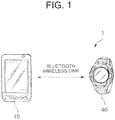
- FIG. 1 is an overall view of a direction display system 1 according to a first embodiment of the present invention.
- the direction display system 1 of the embodiment is constituted to include an electronic timepiece 40 as a direction display device, and a smartphone 10 as a positioning device.
- the electronic timepiece 40 is equipped with a timepiece body and a band, and is a wrist-watch type wearable on a wrist. Both of the electronic timepiece 40 and the smartphone 10 have near field communication functions, and can communicate with each other by Bluetooth communication, for example.
- the smartphone 10 is carried by a user, who wears the electronic timepiece 40, while being put in a backpack, bag, or pocket.
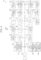
- FIG. 2 is a block diagram illustrating an internal configuration of the electronic timepiece 40.
- FIG. 3 is a block diagram illustrating an internal configuration of the smartphone 10.
- the electronic timepiece 40 includes: a Central Processing Unit (CPU) 41 (a registration instruction detecting section, a registration controlling section, a registration position extracting section, a display controlling section, a position agreement judging section, a direction display controlling section, a position confirming section, and a input/output switch controlling section); a Read Only Memory (ROM) 42; a Random Access Memory (RAM) 43 (a storage section); an operation section 44 (an operation section); a clocking circuit 45; a display section 46 (a display section) and a driver 47 which drives/controls the display section 46; an antenna AN4; a Bluetooth module 48 and a Universal Asynchronous Receiver Transmitter (UART) 49 as a wireless communication section; a vibration motor 50 and a driver 51 for the vibration motor 50; an LED (light-emitting diode) 52 and a driver 53 for the LED 52; a piezo element 54 and a driver 55 for the piezo element 54; a pressure sensor 56 as a barometric
- CPU Central Processing Unit
- the CPU 41 performs integrated control of overall operation of the electronic timepiece 40 and various arithmetic processing.
- the CPU 41 causes the display section 46 to perform time display on the basis of the current time counted by the clocking circuit 45.
- the CPU 41 is configured to calculate an altitude on the basis of barometric pressure data obtained by the pressure sensor 56, and configured to be able to obtain predetermined positional information from the smartphone 10 through the Bluetooth module 48.
- the CPU 41 also detects a posture/orientation of the electronic timepiece 40 on the basis of measurement data obtained by the orientation sensor 58 and the acceleration sensor 60.
- the CPU 41 can be configured to be able to approximate an azimuth of a moving direction of a user from the measurement data.
- the ROM 42 stores various programs and default setting data to be executed by the CPU 41.
- the data stored in the ROM 42 includes a model atmospheric pressure table 421 and a direction display program 422.
- the model atmospheric pressure table 421 and the direction display program 422 constitute a converting section.
- the RAM 43 provides the CPU 41 with a working memory space.
- the RAM 43 also includes a measured-value log storage section 431, and sequentially stores the azimuth of a predetermined direction calculated from the data measured by the orientation sensor 58 and the acceleration sensor 60 at the timing specified on the basis of the registration instruction, and data correlated to the azimuth.
- the operation section 44 is equipped with one or a plurality of button switch, and converts an operation into an input signal, which operation is conducted by a user with respect to the switch, to output the input signal to the CPU 41.
- the operation section 44 can be a touch panel.
- the clocking circuit 45 is a counter which counts the current time to hold the same.
- This counter can be a RAM which merely stores current-time information.
- the current time is read out to be displayed in the display section 46, and/or the current time is compared with set time data regarding various functions to perform various operations.
- the display section 46 is a Liquid Crystal Display (LCD) of dot matrix display system, for example.
- the driver (liquid crystal driver) 47 operates by a control signal transmitted from the CPU 41 to drive the LCD so as to perform a display regarding a specified content such as the current time, setting state, and menu of various functions.
- the display section 46 can be another display section, for example, an organic Electro-Luminescent Display (ELD), and the driver 47 is arbitrary selected depending on the type of the display section 46.
- the electronic timepiece 40 can be an analog type, and the display section 46 can include a dial face with a scale thereon, and a plurality of hands each of which rotates above the dial face.
- the Bluetooth module 48 is a control module for performing Bluetooth communication between the electronic timepiece 40 and an external device(s). As the Bluetooth communication performed by the Bluetooth module 48, also a low-power-consumption standard (Bluetooth Low Energy) can be used.
- the UART 49 performs processing such as serial/parallel conversion with respect to transmission data transmitted from the CPU 41, and transmits the data from the Bluetooth module 48 to the external device.
- the UART 49 also performs processing such as serial/parallel conversion with respect to reception data received from the external device via the Bluetooth module 48, and transmits the data to the CPU 41.
- the vibration motor 50, the LED 52, and the piezo element 54 perform informing operations for a user by emitting vibration, light, and a sound respectively.
- the CPU 41 transmits control signals to the drivers 51, 53 and 55, the drivers 51, 53 and 55 convert the control signals into voltage signals necessary for operating the vibration motor 50, the LED 52, and the piezo element 54, and output the voltage signals, respectively.
- the smartphone 10 includes: a CPU 11 (a positioning controlling section, a first positioning controlling section, and a second positioning controlling section); a ROM 12; a RAM 13; a storage section 14 as an external storage section; an operation section 15; a built-in timepiece 16; a display section 17 and a driver 18 for the display section 17; a speaker 19; a microphone 20; a codec 21, an RF transmission/reception circuit 22; an antenna AN11 for RF transmission/reception; a communication circuit 23; a Bluetooth module 24 as an external communication section; a Universal Asynchronous Receiver Transmitter (UART) 25; an antenna AN12 for transmission/reception in Bluetooth communication; a GPS data receiving/processing section 26 as a positioning section; an antenna AN13 for receiving GPS data; and a bus 27 which connects the CPU 11 and each of the sections.
- a CPU 11 a positioning controlling section, a first positioning controlling section, and a second positioning controlling section
- a ROM 12 read-only memory
- RAM 13 read-only
- the CPU 11 performs integrated control of overall operation of the smartphone 10 and various arithmetic processing.
- the CPU 11 also transmits a control signal(s) to the Bluetooth module 24 on the basis of the information set by inputting operation in the operation section 15 so as to cause the electronic timepiece 40 to transmit the positional information based on the GPS positioning data.
- the ROM 12 stores various programs and default setting data to be executed by the CPU 11.
- the RAM 13 provides the CPU 11 with a working memory space, and stores temporary work data.
- the storage section 14 is a readable/writable nonvolatile memory, and is composed of a flash memory or Electrically Erasable and Programmable Read Only Memory (EEPROM), for example.
- the storage section 14 stores various application programs to be executed in the smartphone 10, and save data and/or set data regarding various functions.
- the application programs include a positional-information transmission program 141 for outputting the positional information requested from the electronic timepiece 40, in a previously-set format, to the electronic timepiece 40 through the Bluetooth module 24 by Bluetooth communication.
- the operation section 15 is an input detecting section which detects an input to the touch panel, namely, an input operation in the display section 17.
- the operation section 15 converts the operation input by the user into an electric signal, and outputs to the CPU 11 the electric signal as an input signal which corresponds to a menu displayed in the display section 17, and to a position and content of the input operation.
- the operation section 15 can include one or a plurality of operation keys and have a configuration to output to the CPU 11 the input signal which is the electric signal obtained by converting the key operation executed by a user.
- the built-in timepiece 16 is a counter which counts the current time to hold the same.
- the current time is read out to be displayed in the display section 17.
- the current time is also compared with the set time data regarding the various functions to perform the various operations.
- the current time held by the built-in timepiece 16 is continually corrected when communicating with a portable base station using the RF transmission/reception circuit 22.
- the display section 17 is composed of a Liquid Crystal Display (LCD), for example.
- the driver (liquid crystal driver) 18 operates by a control signal transmitted from the CPU 11 to drive the LCD so as to perform a display(s) regarding various functions of the smartphone 10.
- the display section 17 can adopt another display system, for example, an organic Electro-Luminescent Display (ELD).
- the driver 18 is arbitrary selected depending on the display system.
- the display section 17 performs the display of menu, as an input screen of the touch panel, for receiving the input operation by a user.
- the speaker 19 converts an electric signal into an audio signal on the basis of a signal from the codec 21 to output audio.
- the microphone 20 detects sound wave to convert it into an electric signal, and outputs it to the codec 21.
- the codec 21 decodes a compression-coded digital audio signal to transmit it as an analog signal to the speaker 19, and also encodes the audio signal input from the microphone 20 to output it to the CPU 11 and/or the communication circuit 23.
- a speaker for talking can be provided separately from a speaker for outputting the audio outside of the smartphone 10.
- the RF transmission/reception circuit 22 performs processing regarding transmission/reception of packet data of telephone audio data, electric mail, etc., which transmission/reception is performed by using the RF transmission/reception antenna AN11 between the smartphone 10 and the portable base station.
- the communication circuit 23 performs various processing to the data transmitted/received by the RF transmission/reception circuit 22, and performs delivery/receipt of the data to/from the CPU 11 and/or the codec 21.
- the Bluetooth module 24 is a control module for performing Bluetooth communication between the smartphone 10 and the other electronics such as the electronic timepiece 40 through the antenna AN 12.
- the UART 25 performs processing such as serial-parallel conversion to the transmission data sent from the CPU 11 to transmit it to the other electronics from the Bluetooth module 24.
- the UART 25 also performs processing such as serial-parallel conversion to the reception data received using the Bluetooth module 24 from the other electronics to output it to the CPU 11.
- the GPS data receiving/processing section 26 demodulates and decodes a satellite signal received from a plurality of GPS satellites through the antenna AN13 to convert it into time data and/or positional data to output it in a predetermined format to the CPU 11.
- a predetermined format for data output National Marine Electronics Association (NMEA)-0183 is used, for example.
- FIG. 4 is a flowchart illustrating a control procedure of measured-value registration processing by the CPU 41 to be executed in the electronic timepiece 40 of the embodiment.
- the execution of the measured-value registration processing is started on the basis of a predetermined input operation by a user in the operation section 44 in the case that the user wishes to register a direction/orientation at an intended spot when ascending (up) a mountain.
- the CPU 41 firstly obtains measured values from the pressure sensor 56, the orientation sensor 58 and the acceleration sensor 60 (Step S101). Then, the CPU 41 calculates an orientation of a predetermined reference direction of the electronic timepiece 40, and causes the measured-value log storage section 431 to store the orientation (Step S102).
- the predetermined reference direction is previously set, which is for example the twelve o'clock direction/position (the direction toward the upper portion of the display section 46) in relation to the center position of the display section 46.
- a user can save the azimuth of an intended direction as registered orientation information by executing a predetermined operation in the operation section 44 while directing the electronic timepiece 40 toward the intended direction.
- the CPU 41 then transmits a request for executing GPS positioning to the smartphone 10 through the Bluetooth module 48 (Step S103).
- the CPU 41 waits until it receives predetermined positioning data (current positional information) based on the positioning result from the smartphone 10, and causes the measured-value log storage section 431 to store the received positioning data and the azimuth data previously stored as the registered orientation information, while correlating the positioning data and the azimuth data to each other (Step S104).
- the positioning data to be stored at this time includes both of plane coordinates and altitude value(s).
- the CPU 41 sets a correction parameter(s) for a conversion formula(s) from the barometric pressure to the altitude using the model atmospheric pressure table 421 on the basis of the altitude data included in the registered positional information and the barometric pressure value measured by the pressure sensor (Step S105). Then, the CPU 41 terminates the measured-value registration processing.
- the measured-value log storage section 431 can store the pieces of data of multiple times of the measured-value registration processing, and a user can repeatedly invoke the measured-value registration processing at an intended spot to sequentially store the registered orientation information and the registered positional information.
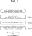
- FIG. 5 is a flowchart illustrating a control procedure by the CPU 11 for positional-information transmitting processing to be executed in the smartphone 10.
- the positional-information transmitting processing is started when the smartphone 10 receives the request for GPS positioning transmitted from the electronic timepiece 40 in Step S103 of the measured-value registration processing executed in the electronic timepiece 40 and the positional-information transmission program 141 is read out and executed.
- the CPU 11 causes the GPS data receiving/processing section 26 to operate to receive radio wave from the GPS satellite(s) and calculate the current location (Step S201). Then, the CPU 11 obtains the necessary positioning data (current positional information) from among the pieces of data output from the GPS data receiving/processing section 26 (Step S202), and transmits the positioning data to the electronic timepiece 40 through the Bluetooth module 24 (Step S204). After that, the CPU 11 terminates the positional-information transmitting processing.
- the smartphone 10 intermittently (for example, at predetermined intervals) performs the GPS positioning regardless of the instruction from the electronic timepiece 40, when the GPS positioning has been performed since the start of the processing of Step S201 up to a predetermined time before (for example, twenty to thirty seconds before), a user can use the last positioning data without performing the GPS positioning separately.
- the current positional data necessary at this point can include a time lag between obtaining timings within a range not causing a relatively large error compared with an amount (for example, 15 to 30 meters) of measurement errors in the pressure sensor and the GPS positioning, and compared with a moving speed (for example, 1 m/s) of a user.
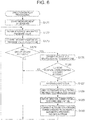
- FIG. 6 is a flowchart illustrating a control procedure of direction display processing according to the embodiment executed by the CPU 41 in the electronic timepiece 40.
- the direction display processing is started when the direction display program 422 is read out on the basis of a predetermined input operation by a user in the operation section 44 at the time of starting descending (down) a mountain and continuously executed.
- the CPU 41 firstly starts sensor measurement by using the pressure sensor 56, the orientation sensor 58 and the acceleration sensor 60 (Step S121). Then, the CPU 41 obtains measured values of barometric pressure at predetermined time intervals according to the default setting or the operation by a user (Step S122), and converts the measured values into the altitude values by using the model atmospheric pressure table 421 and the correction parameter(s) (Step S123).
- the CPU 41 judges whether or not the converted altitude value agrees with any one of the altitudes regarding the positional information stored in the measured-value log storage section 431 (Step S124). In this processing for judging whether or not they agree with each other, in view of possibility of measurement errors and/or convenience for a user, the altitude obtained by converting the barometric pressure does not need to completely agree with the altitude read out from the measured-value log storage section 431, and a difference can exist therebetween.
- a range (predetermined range) of the difference can be a range of ⁇ 10 meters, for example, in view of measurement error that may appear within equal widths in upper and lower directions, or can be a range extending in a plus direction in view of a situation of descending a mountain and/or in view of a difference between moving speeds when ascending a mountain and when descending a mountain.
- the CPU 41 extracts the positioning data determined to agree with the converted altitude value, and transmits the request for GPS positioning to the smartphone 10 through the Bluetooth module 48 (Step S125).
- the positional-information obtaining processing is started by reading out the positional-information transmission program 141 similarly to the case of the request in the measured-value registration processing, and the predetermined positioning data regarding the positioning result is transmitted to the electronic timepiece 40.
- the CPU 41 judges whether or not the position/location based on the received positioning data agrees with the position/location based on the positioning data extracted in the processing of Step S125 (Step S126). Also in this case, the CPU 41 can perform the agreement judgment while taking account of not only complete agreement but also the acceptable difference (predetermined distance). The CPU 41 also can perform detailed settings for the acceptable difference depending on the positions of both spots, for example, depending on a positional relationship such as an inclination angle between the spots and a difference between the azimuth therebetween and the azimuth of the moving direction from the current position. When judging that the position of the received data does not agree with the position of the stored data, the processing by the CPU 41 returns to the Step S122.
- the CPU 41 When judging that the position of the received data agrees with the position of the stored data, the CPU 41 performs the informing operation (Step S127). As the informing operation, an operation(s) of any of the vibration motor 50, the LED 52 and the piezo element 54, or an operation of combination thereof is selected on the basis of the setting by a user. The CPU 41 then identifies the posture/orientation of the electronic timepiece 40 on the basis of the measured values of the acceleration sensor and the orientation sensor (Step S128), and causes the display section 46 to display the direction corresponding to the azimuth stored in the measured-value log storage section 431 depending on the posture/orientation of the electronic timepiece 40 (Step S129).
- the CPU 41 sets the correction parameters for the conversion formula using the model atmospheric pressure table 421 on the basis of the GPS positioning altitude obtained from the smartphone 10 and the pressure value measured by the pressure sensor (Step S130). Then, the processing by the CPU 41 returns to the Step S122.
- the display in the display section 46 can be performed when detecting the situation that a user notices the informing operation and sets the posture/orientation of the electronic timepiece 40 to the browsing state of the display section 46, or when detecting the situation that a user who notices the informing operation performs the predetermining operation in the operation section 44.
- the display in the display section 46 can be kept on for a predetermined time, or terminated on the basis of a predetermined operation by a user in the operation section 44.
- FIG. 7 is a diagram for explaining about specific examples of the measured-value registration processing and the direction display processing of the embodiment. There is herein described the case of traveling back and forth between the starting point of the climbing, namely spot A, and the summit, namely spot E, in the mountain climbing route as indicated with a broken line.
- Step S101 When the input operation is performed to obtain the measured values of the pressure sensor 56, the orientation sensor 58 and the acceleration sensor 60 (Step S101) and a user performs setting and operation to obtain the azimuth of the direction (arrowed direction) along which the user has climbed, namely, 180-degree direction with respect to the northerly direction (upward direction in FIG. 7 ) at spot B which is of a branching point, for example (Step S102), the request for the GPS positioning is transmitted to the smartphone 10 (Step S103) to obtain the positioning data, and this positioning data and the obtained azimuth are registered while they are correlated to each other (Steps S102, S104).
- the direction (150-degree direction) along the branch toward the valley route is registered at spot C which is of a junction between a ridge line and a traverse route, for example.
- spot C which is of a junction between a ridge line and a traverse route, for example.
- a ridge line direction (220-degree direction) along which the climbing trail extends can be registered.
- the conversion formula for converting the measured value (barometric pressure) into the altitude value is continually corrected (Step S105).
- Step S121 When a user performs the operation to activate the direction display processing at the start of descending a mountain at spot E which is of the summit, the pressure sensor 56, the orientation sensor 58 and the acceleration sensor 60 start continuous measurements (Step S121).
- the digitally-sampled measured values of barometric pressure are obtained at the predetermined intervals (Step S122) to be converted into the altitude values (Step S123), and each converted altitude is compared with the altitude values regarding the positioning data stored in the measured-value log storage section 431 (Step S124).
- the request for GPS positioning is transmitted to the smartphone 10 (Step S125).
- Step S126 When the spots compared with each other are determined to be the same position (Step S126: “YES") by comparing the positioning data received/obtained from the smartphone 10 with the positioning data corresponding to the detected (extracted) altitude value, the informing operation using the vibration motor 50, the LED 52 and/or the piezo element 54 is performed (Step S127), and the descending-mountain direction/orientation is displayed in the display section 46 (Steps S128, S129).
- Step S124 when spot G existing between saddle F and spot D has the same altitude as that of spot C, it is detected that the altitude of spot G agrees with the altitude of spot C (Step S124: "YES"), and the request for GPS positioning is transmitted to the smartphone 10 (Step S125).
- Step S126 because horizontal positions of spot G and spot C are determined to be different from each other (Step S126: “NO") on the basis of the positioning data received from the smartphone 10, the informing operation (Step S127) or the operation of the direction display (Steps S128, S129) is not performed.
- the altitude values of all of the spots B, C and D are compared with the altitudes obtained based on the measurement by the pressure sensor 56 every time, such comparison and detection can be performed only at spot D when it is known that the planned route is same as the last route and in opposite direction thereto. After a user reaches spot D and the moving direction from that spot is indicated, such comparison and detection can be performed only at spot C. After a user reaches spot C and the moving direction from that spot is indicated, such comparison and detection can be performed only at spot B.
- the direction display system 1 of the first embodiment is composed of the electronic timepiece 40 and the smartphone 10 which can perform near-field wireless communication with each other.
- the electronic timepiece 40 is equipped with the pressure sensor 56, the orientation sensor 58 and the acceleration sensor 60, which can continuously obtain the altitude with low power consumption, and which can obtain the azimuth value of the direction which is specified at the time of receiving the registration instruction from the operation section 44.
- the smartphone 10 is equipped with the GPS data receiving/processing section 26, and can intermittently performs the GPS positioning.
- the electronic timepiece 40 obtains the GPS positioning data of the spot from the smartphone 10 and causes the measured-value log storage section 431 to sequentially store the pieces of GPS positioning data while correlating them to the registered orientation information.
- the electronic timepiece 40 obtains the current positional data of the GPS positioning data from the smartphone 10, and judges whether or not the current position/location agrees with the position/location of the GPS positional data stored in the measured-value log storage section 431. Only when it is judged that they agree with each other, the moving direction can be indicated by performing the direction display with respect to the orientation registered at the registration spot.
- the location, the direction and the posture/orientation of the electronic timepiece 40 are ordinary measured by the operations of the pressure sensor 56, the orientation sensor 58 and the acceleration sensor 60, which can suppress power consumption. Accordingly, the size and weight of the electronic timepiece 40 can be reduced, and the electronic timepiece 40 does not become a strain in the case of being worn on a wrist or the like in mountain climbing. Meanwhile, when registering an intended direction, by invoking the smartphone 10 to obtain the current positional data based on the GPS positioning therefrom, the position registration can be surely performed without lowering accuracy of position measurement. This enables easily displaying the intended orientation data at the accurate position registered.
- the smartphone 10 Since the smartphone 10 performs the GPS positioning only when a user wishes to obtain accurate positional data, also power consumption of the smartphone 10 can be reduced. Moreover, it becomes unnecessary to go to the trouble of taking out the smartphone 10 for browse thereof in a place where it is difficult to have a hand free, such as a mountain trail.
- a user By registering the traveling direction for descending a mountain depending on the situation of actual movement/transfer at each spot or on the visually-confirmed situation while climbing a mountain, even in a place which is hard to be discriminated on a map, a user can obtain advantages of not losing a mountain descent direction, of not missing a mountain descent route, and of reducing a risk of going out of the mountain descent route.
- All the processing using the GPS positioning data is executed in the electronic timepiece 40 by using the measured-value log storage section 431, and the smartphone 10 executes only the GPS positioning and transmission of the positioning data. This can avoid putting on the smartphone 10 an excess burden which is because of the other processes.
- the measured-value registration processing in ascending a mountain is performed separately from the direction display processing in descending the mountain, it is unnecessary to execute unnecessary detecting processing regarding the direction display at the stage of performing registration processing in ascending the mountain.
- the vibration motor 50, the LED 52, and the piezo element 54 are provided and the informing operation is performed by the intended way of a user when displaying the traveling direction in the direction display processing, it is possible to avoid the situation that a user does not notice the display and goes along a wrong direction.
- the parameter(s) for converting the measurement value of the pressure sensor 56 into the altitude value by using the model atmospheric pressure table 421 is corrected every time when obtaining the current positional information of the GPS positioning, highly accurate values can be obtained so as to follow a change of barometric pressure even when the barometric pressure changes in the middle of descending a mountain and it is difficult to obtain correct value(s) without correction.
- FIG. 8 is a flowchart of variation of the direction display processing in the electronic timepiece 40 of the above embodiment.
- the measured-value registration processing at the time of ascending a mountain and the direction display processing at the time of descending the mountain are not distinguished from each other and are concurrently executed.
- the CPU 41 judges whether or not memory registration has been requested by the input operation in the operation section 44 (Step S100).
- the control procedure performs the processing of Steps S101 to S105 of the measured-value registration processing. Processes in the other steps excepting Step S100 are similar to those of the above embodiment, and thereby same numerals are used and the descriptions thereof are omitted.
- the direction display can be performed so as to flexibly correspond to the case of including not only a mere back-and-forth route but also a go-around route, drop-by route, etc.
- the internal configuration of the electronic timepiece 40 constituting the direction display system 1 of the second embodiment is same as that of the electronic timepiece 40 of the first embodiment, and the description thereof is omitted.
- FIG. 9 is a block diagram illustrating the internal configuration of the smartphone 10a constituting the direction display system 1 of the second embodiment.
- the smartphone 10a of the second embodiment is same as the smartphone 10 of the first embodiment excepting that the smartphone 10a stores a positional-information processing program 142 and a positional-information storage section 143 in the storage section 14 in stead of the positional-information transmission program 141 stored by the storage section 14 of the smartphone 10, and thereby same numerals are used and the descriptions thereof are omitted.
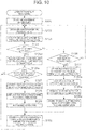
- FIG. 10 is a flowchart illustrating a control procedure of the direction display processing to be executed by the CPU 41 in the electronic timepiece 40 in the direction display system 1 of the second embodiment.
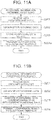
- FIGS. 11A and 11B are flowcharts illustrating control procedures of the positional-information obtaining processing and positional-information comparing processing to be executed by the CPU 11 in the smartphone 10a in the direction display system 1 of the second embodiment.
- the direction display processing to be executed in the electronic timepiece 40 of the second embodiment is same as the direction display processing of the above variation excepting that processes of Steps S125, S126, S102 to S104 are changed to Steps S125a, S126a, S102a to S104a, and thereby same numerals are used and the detailed descriptions thereof are omitted.
- the positional-information obtaining processing is executed by the positional-information processing program 142 read out from the storage section 14.
- processing of Step S203 is added to the positional-information obtaining processing of the first embodiment, and processing of Step S204a is performed in stead of processing of Step S204.
- the smartphone 10a executes the positional-information comparing processing by using the positional-information processing program 142, and Steps S213 and S214 are performed in stead of Step S204 of the positional-information obtaining processing of the first embodiment.
- the other processing is same as those of the first embodiment, and thereby same numerals are used and the detailed descriptions thereof are omitted.
- Step S101 when the result of processing of Step S100 is "YES" and the measurement values of barometric pressure, direction/orientation, and acceleration are obtained (Step S101), the CPU 41 newly sets an ID value for specifying the data and causes the measured-value log storage section 431 to store the azimuth of the specified direction with the ID value (Step S102a). Then, the CPU 41 transmits the request for GPS positioning with the set ID value to the smartphone 10a through the Bluetooth module 48 (Step S103a). When receiving only the altitude data as the current positional information from the smartphone 10a, the CPU 41 causes the measured-value log storage section 431 to store the altitude data while correlating the same with the previously-stored ID value (Step S104a).
- the CPU 11 of the smartphone 10a starts the positional-information obtaining processing as illustrated in FIG. 11A .
- the CPU 11 receives radio wave from the GPS satellite(s) (Step S201), and when obtaining the GPS positioning data (Step S202), causes the positional-information storage section 143 to store the received ID value and the positioning data while correlating them to each other (Step S203). Then, the CPU 11 transmits, as the current positional information, only the altitude data among the positioning result to the electronic timepiece 40 through the Bluetooth module 24 (Step S204a). After that, the CPU 11 terminates the positional-information obtaining processing.
- Step S124 when the result of processing of Step S124 is "YES", as illustrated in FIG. 10 , the CPU 41 transmits the request for GPS positional confirmation, with the ID value corresponding to the extracted altitude value (registered positional information), to the smartphone 10a through the Bluetooth module 48 (Step S125a).
- the CPU 41 merely receives the comparison result from the smartphone 10a.
- the CPU 41 obtains the judgment result on whether or not the current position measured by the GPS positioning agrees with the positioning data correlated to the memory ID value and stored in the positional-information storage section 143 of the smartphone 10a within the difference of a predetermined range, and confirms the content of judgment result (Step S126a).
- the processing by the CPU 41 proceeds to Step S127, and when judging that they do not agree with each other, the processing by the CPU 41 returns to Step S122.
- the CPU 11 of the smartphone 10a executes the positional-information comparing processing.
- the CPU 11 receives radio wave from the GPS satellite (Step S201), and when obtaining the GPS positioning data (Step S202), the CPU 11 compares this GPS positioning data with the positioning data stored in the positional-information storage section 143 correspondingly to the ID value transmitted with the request for GPS positional confirmation from the electronic timepiece 40, and judges whether or not they are agree with each other within the difference of a predetermined range (Step S213). Then, the CPU 11 transmits the comparison result as a binary signal indicating "YES" or "NO" to the electronic timepiece 40 (Step S214). After that, the CPU 11 terminates the positional-information comparing processing.
- the direction display system 1 of the second embodiment three-dimensional positional data obtained by the GPS positioning by the smartphone 10 is stored in the positional-information storage section 143 when registering the moving direction data, and among the pieces of data, only altitude-directional data is transmitted to the electronic timepiece 40 to be stored in the measured-value log storage section 431. Then, when the altitude obtained by conversion in the extracting processing regarding the direction display by the electronic timepiece 40 agrees with the registered altitude, after the smartphone 10 executes all of the positional-agreement judging processing, only the judgment result is returned to the electronic timepiece 40.
- the smartphone 10 does not need to transmit unnecessary data for the electronic timepiece 40, communications traffic can be reduced and electric power and/or time for communication can be suppressed. In addition, storage capacity necessary for the electrical timepiece 40 can be reduced.
- the present invention is not limited to the above embodiments, and various changes can be added thereto.
- the above embodiments identify the posture/orientation of the electrical timepiece 40 by using the acceleration sensor 60 to perform the direction measurement and/or the display, it is also possible to perform the measurement and/or display without using the acceleration sensor 60 on the premise that a user disposes the electronic timepiece 40 in a predetermined posture/orientation.
- the above embodiments describe the configuration in which the measured-value registration processing and the direction display processing are completely separated from each other and the configuration in which they are executed concurrently, but the present invention can adopt a configuration which does not belong to these configurations. For example, it is possible to cause only the measured-value registration processing to be executed by the middle of processing and then cause the measured-value registration processing and the direction display processing to be executed concurrently.
- the above embodiments describe the configuration in which the electronic timepiece 40 holds and utilizes all of the positioning data (current positional information) measured by the GPS positioning, and the configuration in which the smartphone 10 holds and utilizes the data of horizontal-directional position among the pieces of the current positional information measured by the GPS positioning, but the present invention can adopt another configuration.
- a bit of difference is allowed when executing the processing of agreement judgment of the altitude and/or current position/location (Steps S124 and S126).
- the set difference is large or when there is a continuous road including up and down minutely repeated, and when registrations has been performed successively at spots adjacent to one another, there is a possibility that a plurality of registration spots are mistakenly detected, especially in a complicated climbing trail such as a zigzag road.
- the present invention is not limited thereto.
- a dedicated GPS logger and/or positioning device can be used in stead of the smartphone 10.
- the data obtained in the ordinary operation of GPS positioning can be directly acquired by the electronic timepiece 40 to be used therein, and the electronic timepiece 40 does not need to request the GPS positioning separately.
- the present invention can be applied to not only the electronic timepiece 40 but also another wrist-wearing-type electronic device such as a pedometer.
- the electronic device is not limited to the wrist-wearing-type one as long as it is usable in a climbing trail or the like, and as long as it is portable electronic device easily browsed, for example, by being dangled from a neck.
- the Bluetooth is cited as the example of the way of the near-field wireless communication, but the way is not limited thereto. It can be another way, for example, infrared communication, Ultra Wide Band (UWB), etc.
- UWB Ultra Wide Band
Landscapes
- Engineering & Computer Science (AREA)
- Remote Sensing (AREA)
- Radar, Positioning & Navigation (AREA)
- Physics & Mathematics (AREA)
- General Physics & Mathematics (AREA)
- Environmental & Geological Engineering (AREA)
- Life Sciences & Earth Sciences (AREA)
- General Life Sciences & Earth Sciences (AREA)
- Geology (AREA)
- Automation & Control Theory (AREA)
- Signal Processing (AREA)
- Computer Networks & Wireless Communication (AREA)
- Navigation (AREA)
- Telephone Function (AREA)
- Electric Clocks (AREA)
- Position Fixing By Use Of Radio Waves (AREA)
Applications Claiming Priority (1)
| Application Number | Priority Date | Filing Date | Title |
|---|---|---|---|
| JP2012151017A JP6035915B2 (ja) | 2012-07-05 | 2012-07-05 | 方角表示装置及び方角表示システム |
Publications (3)
| Publication Number | Publication Date |
|---|---|
| EP2682714A2 EP2682714A2 (en) | 2014-01-08 |
| EP2682714A3 EP2682714A3 (en) | 2015-04-15 |
| EP2682714B1 true EP2682714B1 (en) | 2019-09-25 |
Family
ID=48699541
Family Applications (1)
| Application Number | Title | Priority Date | Filing Date |
|---|---|---|---|
| EP13171575.7A Active EP2682714B1 (en) | 2012-07-05 | 2013-06-12 | Direction display device and direction display system |
Country Status (4)
| Country | Link |
|---|---|
| US (1) | US8825086B2 (cg-RX-API-DMAC7.html) |
| EP (1) | EP2682714B1 (cg-RX-API-DMAC7.html) |
| JP (1) | JP6035915B2 (cg-RX-API-DMAC7.html) |
| CN (1) | CN103528565B (cg-RX-API-DMAC7.html) |
Families Citing this family (22)
| Publication number | Priority date | Publication date | Assignee | Title |
|---|---|---|---|---|
| JP5821726B2 (ja) * | 2012-03-19 | 2015-11-24 | カシオ計算機株式会社 | イベント報知装置、及び、イベント報知システム |
| CN104154906A (zh) * | 2014-08-11 | 2014-11-19 | 江苏艾倍科科技有限公司 | 一种北斗双模定位指南针 |
| JP5704496B2 (ja) * | 2014-09-19 | 2015-04-22 | 森 圭司 | 情報処理システム、携帯端末の制御プログラム、および電子機器 |
| US10240929B2 (en) | 2014-10-01 | 2019-03-26 | Intel Corporation | Methods and systems for vertical trajectory determination and automatic jump detection |
| EP3046342A1 (en) * | 2015-01-15 | 2016-07-20 | SwissSavior AG | Beacon device and its use |
| JP6547314B2 (ja) * | 2015-02-03 | 2019-07-24 | カシオ計算機株式会社 | 電子機器、計測システム、計測データ取得方法及びプログラム |
| US10067477B2 (en) | 2015-10-27 | 2018-09-04 | Timex Group Usa, Inc. | Wristwearable device with travel information indicators |
| JP2017129441A (ja) * | 2016-01-20 | 2017-07-27 | セイコーエプソン株式会社 | 電子機器、高度算出プログラム、および高度算出方法 |
| JP6685735B2 (ja) * | 2016-01-21 | 2020-04-22 | セイコーインスツル株式会社 | 高度計および電子時計 |
| JP2018009961A (ja) * | 2016-06-30 | 2018-01-18 | セイコーインスツル株式会社 | 電子機器、表示システム、電子時計およびプログラム |
| JP6699596B2 (ja) * | 2017-02-28 | 2020-05-27 | カシオ計算機株式会社 | 情報取得方法、無線通信装置、及びプログラム |
| US10602326B2 (en) | 2017-10-23 | 2020-03-24 | Polaris Wireless, Inc. | Detection of the occurrence of an event, based on barometric pressure measurements |
| US11009376B2 (en) * | 2017-10-23 | 2021-05-18 | Polaris Wireless, Inc. | Estimation of the location of a wireless terminal, based on characterizing a pressure wave |
| JP6981375B2 (ja) * | 2018-07-20 | 2021-12-15 | カシオ計算機株式会社 | 電子機器及び位置情報取得方法 |
| JP7131266B2 (ja) | 2018-10-01 | 2022-09-06 | カシオ計算機株式会社 | 情報端末、リスト情報機器、及びそれらを備えるシステム |
| WO2020095574A1 (ja) * | 2018-11-07 | 2020-05-14 | ソニーセミコンダクタソリューションズ株式会社 | 受信装置、プログラム及び受信方法 |
| JP6737968B1 (ja) * | 2020-02-07 | 2020-08-12 | 亮輔 奥田 | 歩行者信号識別装置 |
| JP7092159B2 (ja) * | 2020-03-19 | 2022-06-28 | カシオ計算機株式会社 | 情報処理装置、行動解析システム、行動解析方法及びプログラム |
| JP6825739B2 (ja) * | 2020-04-28 | 2021-02-03 | カシオ計算機株式会社 | 情報取得方法、無線通信装置、及びプログラム |
| JP7306366B2 (ja) * | 2020-11-16 | 2023-07-11 | 横河電機株式会社 | 機器登録端末、機器登録方法、および、機器登録プログラム |
| CN115560748A (zh) * | 2021-07-01 | 2023-01-03 | 本田技研工业株式会社 | 系统和方法 |
| US11933906B2 (en) | 2021-09-21 | 2024-03-19 | Google Llc | Wearable accessories for determining accurate elevation information for navigation |
Family Cites Families (15)
| Publication number | Priority date | Publication date | Assignee | Title |
|---|---|---|---|---|
| JPH04131711A (ja) * | 1990-09-22 | 1992-05-06 | Aisin Seiki Co Ltd | 自動車用ルートガイド装置 |
| JP4081898B2 (ja) * | 1998-12-18 | 2008-04-30 | カシオ計算機株式会社 | 地図表示装置 |
| US6529827B1 (en) * | 1999-11-01 | 2003-03-04 | Garmin Corporation | GPS device with compass and altimeter and method for displaying navigation information |
| JP2001215162A (ja) * | 2000-01-31 | 2001-08-10 | Seiko Instruments Inc | 携帯型測定器および表示方法 |
| JP4557238B2 (ja) * | 2001-02-06 | 2010-10-06 | 本田技研工業株式会社 | 二輪車の進行方向誘導装置 |
| US20030014212A1 (en) * | 2001-07-12 | 2003-01-16 | Ralston Stuart E. | Augmented vision system using wireless communications |
| JP2003065784A (ja) * | 2001-08-28 | 2003-03-05 | Vertex Standard Co Ltd | Gpsナビゲーション装置 |
| JP2005274426A (ja) * | 2004-03-25 | 2005-10-06 | Seiko Epson Corp | 環境情報処理システム、端末装置、環境情報処理方法、端末装置の制御方法、端末装置の制御プログラム及び端末装置の制御プログラムを記録したコンピュータ読み取り可能な記録媒体 |
| US7706977B2 (en) * | 2004-10-26 | 2010-04-27 | Honeywell International Inc. | Personal navigation device for use with portable device |
| JP2006145340A (ja) * | 2004-11-18 | 2006-06-08 | Sharp Corp | 携帯情報端末及び高度測定システム |
| JP5074157B2 (ja) | 2007-11-09 | 2012-11-14 | ソフトバンクモバイル株式会社 | 時刻修正システム、携帯電話装置及び腕時計型端末装置 |
| CN201170799Y (zh) * | 2008-03-20 | 2008-12-24 | 长天科技股份有限公司 | 具高度及方向校正的卫星定位系统接收装置 |
| JP5245705B2 (ja) * | 2008-10-14 | 2013-07-24 | セイコーエプソン株式会社 | 登山支援情報処理装置 |
| JP2010223820A (ja) * | 2009-03-24 | 2010-10-07 | Seiko Epson Corp | 携帯型行程スケジュール管理装置 |
| JP2012251960A (ja) * | 2011-06-07 | 2012-12-20 | Casio Comput Co Ltd | 腕装着型端末、ナビゲーションシステム、及び、プログラム |
-
2012
- 2012-07-05 JP JP2012151017A patent/JP6035915B2/ja active Active
-
2013
- 2013-06-12 EP EP13171575.7A patent/EP2682714B1/en active Active
- 2013-06-25 US US13/926,770 patent/US8825086B2/en active Active
- 2013-07-04 CN CN201310279642.5A patent/CN103528565B/zh active Active
Non-Patent Citations (1)
| Title |
|---|
| None * |
Also Published As
| Publication number | Publication date |
|---|---|
| JP2014013204A (ja) | 2014-01-23 |
| EP2682714A2 (en) | 2014-01-08 |
| EP2682714A3 (en) | 2015-04-15 |
| CN103528565B (zh) | 2016-05-11 |
| US20140011540A1 (en) | 2014-01-09 |
| CN103528565A (zh) | 2014-01-22 |
| JP6035915B2 (ja) | 2016-11-30 |
| US8825086B2 (en) | 2014-09-02 |
Similar Documents
| Publication | Publication Date | Title |
|---|---|---|
| EP2682714B1 (en) | Direction display device and direction display system | |
| JP5652418B2 (ja) | 高度情報取得装置、及び、高度情報取得システム | |
| US8630798B2 (en) | Electronic system and method for personal navigation | |
| US10321293B2 (en) | Methods for communicating sensor data between devices | |
| JP2012251960A (ja) | 腕装着型端末、ナビゲーションシステム、及び、プログラム | |
| JP5648447B2 (ja) | 周遊ルート生成装置、周遊ルート生成方法、及びプログラム | |
| WO2012045483A1 (en) | Gps odometer | |
| JPH11194033A (ja) | 携帯用位置検出装置および位置管理システム | |
| US20180112986A1 (en) | Navigation Device | |
| WO2016167230A1 (ja) | ウェアラブルナビゲーションシステム、指輪・腕時計・腕輪、プログラム | |
| JP6269237B2 (ja) | 電子時計及び速度計測管理システム | |
| WO2012045484A1 (en) | Gps-calibrated pedometer | |
| US10036637B2 (en) | Electronic device and information notification method | |
| JP6477676B2 (ja) | 経路抽出装置、経路抽出方法及びプログラム | |
| JP2008268098A (ja) | 携帯ナビゲーション装置 | |
| KR20080063677A (ko) | 네비게이션 시스템 및 그 운용 방법 | |
| KR100701739B1 (ko) | 이동 정보를 이용하는 장치 | |
| KR20050032549A (ko) | 지피에스 시계 | |
| JP2013072668A (ja) | 気圧測定装置 | |
| JP2016148612A (ja) | 電子機器及びプログラム | |
| KR20100040096A (ko) | 조난 방지를 위한 나침반 기능이 구비된 휴대용 단말기 |
Legal Events
| Date | Code | Title | Description |
|---|---|---|---|
| PUAI | Public reference made under article 153(3) epc to a published international application that has entered the european phase |
Free format text: ORIGINAL CODE: 0009012 |
|
| 17P | Request for examination filed |
Effective date: 20130612 |
|
| AK | Designated contracting states |
Kind code of ref document: A2 Designated state(s): AL AT BE BG CH CY CZ DE DK EE ES FI FR GB GR HR HU IE IS IT LI LT LU LV MC MK MT NL NO PL PT RO RS SE SI SK SM TR |
|
| AX | Request for extension of the european patent |
Extension state: BA ME |
|
| PUAL | Search report despatched |
Free format text: ORIGINAL CODE: 0009013 |
|
| AK | Designated contracting states |
Kind code of ref document: A3 Designated state(s): AL AT BE BG CH CY CZ DE DK EE ES FI FR GB GR HR HU IE IS IT LI LT LU LV MC MK MT NL NO PL PT RO RS SE SI SK SM TR |
|
| AX | Request for extension of the european patent |
Extension state: BA ME |
|
| RIC1 | Information provided on ipc code assigned before grant |
Ipc: G01C 17/00 20060101ALI20150311BHEP Ipc: G01C 21/08 20060101ALI20150311BHEP Ipc: G01C 5/06 20060101AFI20150311BHEP |
|
| STAA | Information on the status of an ep patent application or granted ep patent |
Free format text: STATUS: EXAMINATION IS IN PROGRESS |
|
| 17Q | First examination report despatched |
Effective date: 20171120 |
|
| GRAP | Despatch of communication of intention to grant a patent |
Free format text: ORIGINAL CODE: EPIDOSNIGR1 |
|
| STAA | Information on the status of an ep patent application or granted ep patent |
Free format text: STATUS: GRANT OF PATENT IS INTENDED |
|
| INTG | Intention to grant announced |
Effective date: 20190408 |
|
| GRAS | Grant fee paid |
Free format text: ORIGINAL CODE: EPIDOSNIGR3 |
|
| GRAA | (expected) grant |
Free format text: ORIGINAL CODE: 0009210 |
|
| STAA | Information on the status of an ep patent application or granted ep patent |
Free format text: STATUS: THE PATENT HAS BEEN GRANTED |
|
| AK | Designated contracting states |
Kind code of ref document: B1 Designated state(s): AL AT BE BG CH CY CZ DE DK EE ES FI FR GB GR HR HU IE IS IT LI LT LU LV MC MK MT NL NO PL PT RO RS SE SI SK SM TR |
|
| REG | Reference to a national code |
Ref country code: GB Ref legal event code: FG4D |
|
| REG | Reference to a national code |
Ref country code: CH Ref legal event code: EP |
|
| REG | Reference to a national code |
Ref country code: AT Ref legal event code: REF Ref document number: 1184231 Country of ref document: AT Kind code of ref document: T Effective date: 20191015 |
|
| REG | Reference to a national code |
Ref country code: IE Ref legal event code: FG4D |
|
| REG | Reference to a national code |
Ref country code: DE Ref legal event code: R096 Ref document number: 602013060883 Country of ref document: DE |
|
| REG | Reference to a national code |
Ref country code: NL Ref legal event code: MP Effective date: 20190925 |
|
| PG25 | Lapsed in a contracting state [announced via postgrant information from national office to epo] |
Ref country code: NO Free format text: LAPSE BECAUSE OF FAILURE TO SUBMIT A TRANSLATION OF THE DESCRIPTION OR TO PAY THE FEE WITHIN THE PRESCRIBED TIME-LIMIT Effective date: 20191225 Ref country code: LT Free format text: LAPSE BECAUSE OF FAILURE TO SUBMIT A TRANSLATION OF THE DESCRIPTION OR TO PAY THE FEE WITHIN THE PRESCRIBED TIME-LIMIT Effective date: 20190925 Ref country code: BG Free format text: LAPSE BECAUSE OF FAILURE TO SUBMIT A TRANSLATION OF THE DESCRIPTION OR TO PAY THE FEE WITHIN THE PRESCRIBED TIME-LIMIT Effective date: 20191225 Ref country code: FI Free format text: LAPSE BECAUSE OF FAILURE TO SUBMIT A TRANSLATION OF THE DESCRIPTION OR TO PAY THE FEE WITHIN THE PRESCRIBED TIME-LIMIT Effective date: 20190925 Ref country code: HR Free format text: LAPSE BECAUSE OF FAILURE TO SUBMIT A TRANSLATION OF THE DESCRIPTION OR TO PAY THE FEE WITHIN THE PRESCRIBED TIME-LIMIT Effective date: 20190925 Ref country code: SE Free format text: LAPSE BECAUSE OF FAILURE TO SUBMIT A TRANSLATION OF THE DESCRIPTION OR TO PAY THE FEE WITHIN THE PRESCRIBED TIME-LIMIT Effective date: 20190925 |
|
| REG | Reference to a national code |
Ref country code: LT Ref legal event code: MG4D |
|
| PG25 | Lapsed in a contracting state [announced via postgrant information from national office to epo] |
Ref country code: GR Free format text: LAPSE BECAUSE OF FAILURE TO SUBMIT A TRANSLATION OF THE DESCRIPTION OR TO PAY THE FEE WITHIN THE PRESCRIBED TIME-LIMIT Effective date: 20191226 Ref country code: LV Free format text: LAPSE BECAUSE OF FAILURE TO SUBMIT A TRANSLATION OF THE DESCRIPTION OR TO PAY THE FEE WITHIN THE PRESCRIBED TIME-LIMIT Effective date: 20190925 Ref country code: RS Free format text: LAPSE BECAUSE OF FAILURE TO SUBMIT A TRANSLATION OF THE DESCRIPTION OR TO PAY THE FEE WITHIN THE PRESCRIBED TIME-LIMIT Effective date: 20190925 |
|
| REG | Reference to a national code |
Ref country code: AT Ref legal event code: MK05 Ref document number: 1184231 Country of ref document: AT Kind code of ref document: T Effective date: 20190925 |
|
| PG25 | Lapsed in a contracting state [announced via postgrant information from national office to epo] |
Ref country code: AL Free format text: LAPSE BECAUSE OF FAILURE TO SUBMIT A TRANSLATION OF THE DESCRIPTION OR TO PAY THE FEE WITHIN THE PRESCRIBED TIME-LIMIT Effective date: 20190925 Ref country code: AT Free format text: LAPSE BECAUSE OF FAILURE TO SUBMIT A TRANSLATION OF THE DESCRIPTION OR TO PAY THE FEE WITHIN THE PRESCRIBED TIME-LIMIT Effective date: 20190925 Ref country code: IT Free format text: LAPSE BECAUSE OF FAILURE TO SUBMIT A TRANSLATION OF THE DESCRIPTION OR TO PAY THE FEE WITHIN THE PRESCRIBED TIME-LIMIT Effective date: 20190925 Ref country code: PL Free format text: LAPSE BECAUSE OF FAILURE TO SUBMIT A TRANSLATION OF THE DESCRIPTION OR TO PAY THE FEE WITHIN THE PRESCRIBED TIME-LIMIT Effective date: 20190925 Ref country code: EE Free format text: LAPSE BECAUSE OF FAILURE TO SUBMIT A TRANSLATION OF THE DESCRIPTION OR TO PAY THE FEE WITHIN THE PRESCRIBED TIME-LIMIT Effective date: 20190925 Ref country code: RO Free format text: LAPSE BECAUSE OF FAILURE TO SUBMIT A TRANSLATION OF THE DESCRIPTION OR TO PAY THE FEE WITHIN THE PRESCRIBED TIME-LIMIT Effective date: 20190925 Ref country code: NL Free format text: LAPSE BECAUSE OF FAILURE TO SUBMIT A TRANSLATION OF THE DESCRIPTION OR TO PAY THE FEE WITHIN THE PRESCRIBED TIME-LIMIT Effective date: 20190925 Ref country code: PT Free format text: LAPSE BECAUSE OF FAILURE TO SUBMIT A TRANSLATION OF THE DESCRIPTION OR TO PAY THE FEE WITHIN THE PRESCRIBED TIME-LIMIT Effective date: 20200127 Ref country code: ES Free format text: LAPSE BECAUSE OF FAILURE TO SUBMIT A TRANSLATION OF THE DESCRIPTION OR TO PAY THE FEE WITHIN THE PRESCRIBED TIME-LIMIT Effective date: 20190925 |
|
| PG25 | Lapsed in a contracting state [announced via postgrant information from national office to epo] |
Ref country code: IS Free format text: LAPSE BECAUSE OF FAILURE TO SUBMIT A TRANSLATION OF THE DESCRIPTION OR TO PAY THE FEE WITHIN THE PRESCRIBED TIME-LIMIT Effective date: 20200224 Ref country code: SK Free format text: LAPSE BECAUSE OF FAILURE TO SUBMIT A TRANSLATION OF THE DESCRIPTION OR TO PAY THE FEE WITHIN THE PRESCRIBED TIME-LIMIT Effective date: 20190925 Ref country code: CZ Free format text: LAPSE BECAUSE OF FAILURE TO SUBMIT A TRANSLATION OF THE DESCRIPTION OR TO PAY THE FEE WITHIN THE PRESCRIBED TIME-LIMIT Effective date: 20190925 Ref country code: SM Free format text: LAPSE BECAUSE OF FAILURE TO SUBMIT A TRANSLATION OF THE DESCRIPTION OR TO PAY THE FEE WITHIN THE PRESCRIBED TIME-LIMIT Effective date: 20190925 |
|
| REG | Reference to a national code |
Ref country code: DE Ref legal event code: R097 Ref document number: 602013060883 Country of ref document: DE |
|
| PG2D | Information on lapse in contracting state deleted |
Ref country code: IS |
|
| PG25 | Lapsed in a contracting state [announced via postgrant information from national office to epo] |
Ref country code: DK Free format text: LAPSE BECAUSE OF FAILURE TO SUBMIT A TRANSLATION OF THE DESCRIPTION OR TO PAY THE FEE WITHIN THE PRESCRIBED TIME-LIMIT Effective date: 20190925 Ref country code: IS Free format text: LAPSE BECAUSE OF FAILURE TO SUBMIT A TRANSLATION OF THE DESCRIPTION OR TO PAY THE FEE WITHIN THE PRESCRIBED TIME-LIMIT Effective date: 20200126 |
|
| PLBE | No opposition filed within time limit |
Free format text: ORIGINAL CODE: 0009261 |
|
| STAA | Information on the status of an ep patent application or granted ep patent |
Free format text: STATUS: NO OPPOSITION FILED WITHIN TIME LIMIT |
|
| 26N | No opposition filed |
Effective date: 20200626 |
|
| PG25 | Lapsed in a contracting state [announced via postgrant information from national office to epo] |
Ref country code: SI Free format text: LAPSE BECAUSE OF FAILURE TO SUBMIT A TRANSLATION OF THE DESCRIPTION OR TO PAY THE FEE WITHIN THE PRESCRIBED TIME-LIMIT Effective date: 20190925 |
|
| PG25 | Lapsed in a contracting state [announced via postgrant information from national office to epo] |
Ref country code: MC Free format text: LAPSE BECAUSE OF FAILURE TO SUBMIT A TRANSLATION OF THE DESCRIPTION OR TO PAY THE FEE WITHIN THE PRESCRIBED TIME-LIMIT Effective date: 20190925 |
|
| REG | Reference to a national code |
Ref country code: CH Ref legal event code: PL |
|
| PG25 | Lapsed in a contracting state [announced via postgrant information from national office to epo] |
Ref country code: LU Free format text: LAPSE BECAUSE OF NON-PAYMENT OF DUE FEES Effective date: 20200612 |
|
| REG | Reference to a national code |
Ref country code: BE Ref legal event code: MM Effective date: 20200630 |
|
| PG25 | Lapsed in a contracting state [announced via postgrant information from national office to epo] |
Ref country code: CH Free format text: LAPSE BECAUSE OF NON-PAYMENT OF DUE FEES Effective date: 20200630 Ref country code: LI Free format text: LAPSE BECAUSE OF NON-PAYMENT OF DUE FEES Effective date: 20200630 Ref country code: IE Free format text: LAPSE BECAUSE OF NON-PAYMENT OF DUE FEES Effective date: 20200612 |
|
| PG25 | Lapsed in a contracting state [announced via postgrant information from national office to epo] |
Ref country code: BE Free format text: LAPSE BECAUSE OF NON-PAYMENT OF DUE FEES Effective date: 20200630 |
|
| PG25 | Lapsed in a contracting state [announced via postgrant information from national office to epo] |
Ref country code: TR Free format text: LAPSE BECAUSE OF FAILURE TO SUBMIT A TRANSLATION OF THE DESCRIPTION OR TO PAY THE FEE WITHIN THE PRESCRIBED TIME-LIMIT Effective date: 20190925 Ref country code: MT Free format text: LAPSE BECAUSE OF FAILURE TO SUBMIT A TRANSLATION OF THE DESCRIPTION OR TO PAY THE FEE WITHIN THE PRESCRIBED TIME-LIMIT Effective date: 20190925 Ref country code: CY Free format text: LAPSE BECAUSE OF FAILURE TO SUBMIT A TRANSLATION OF THE DESCRIPTION OR TO PAY THE FEE WITHIN THE PRESCRIBED TIME-LIMIT Effective date: 20190925 |
|
| PG25 | Lapsed in a contracting state [announced via postgrant information from national office to epo] |
Ref country code: MK Free format text: LAPSE BECAUSE OF FAILURE TO SUBMIT A TRANSLATION OF THE DESCRIPTION OR TO PAY THE FEE WITHIN THE PRESCRIBED TIME-LIMIT Effective date: 20190925 |
|
| PGFP | Annual fee paid to national office [announced via postgrant information from national office to epo] |
Ref country code: DE Payment date: 20250429 Year of fee payment: 13 |
|
| PGFP | Annual fee paid to national office [announced via postgrant information from national office to epo] |
Ref country code: GB Payment date: 20250501 Year of fee payment: 13 |
|
| PGFP | Annual fee paid to national office [announced via postgrant information from national office to epo] |
Ref country code: FR Payment date: 20250508 Year of fee payment: 13 |