EP2674144A1 - Dosierscheibe und Kapselfülleinrichtung mit Dosierscheibe - Google Patents
Dosierscheibe und Kapselfülleinrichtung mit Dosierscheibe Download PDFInfo
- Publication number
- EP2674144A1 EP2674144A1 EP13002884.8A EP13002884A EP2674144A1 EP 2674144 A1 EP2674144 A1 EP 2674144A1 EP 13002884 A EP13002884 A EP 13002884A EP 2674144 A1 EP2674144 A1 EP 2674144A1
- Authority
- EP
- European Patent Office
- Prior art keywords
- metering
- base body
- thickness
- dosing
- disk
- Prior art date
- Legal status (The legal status is an assumption and is not a legal conclusion. Google has not performed a legal analysis and makes no representation as to the accuracy of the status listed.)
- Granted
Links
Images

Classifications
-
- B—PERFORMING OPERATIONS; TRANSPORTING
- B65—CONVEYING; PACKING; STORING; HANDLING THIN OR FILAMENTARY MATERIAL
- B65B—MACHINES, APPARATUS OR DEVICES FOR, OR METHODS OF, PACKAGING ARTICLES OR MATERIALS; UNPACKING
- B65B1/00—Packaging fluent solid material, e.g. powders, granular or loose fibrous material, loose masses of small articles, in individual containers or receptacles, e.g. bags, sacks, boxes, cartons, cans, or jars
- B65B1/30—Devices or methods for controlling or determining the quantity or quality or the material fed or filled
- B65B1/36—Devices or methods for controlling or determining the quantity or quality or the material fed or filled by volumetric devices or methods
-
- B—PERFORMING OPERATIONS; TRANSPORTING
- B65—CONVEYING; PACKING; STORING; HANDLING THIN OR FILAMENTARY MATERIAL
- B65B—MACHINES, APPARATUS OR DEVICES FOR, OR METHODS OF, PACKAGING ARTICLES OR MATERIALS; UNPACKING
- B65B1/00—Packaging fluent solid material, e.g. powders, granular or loose fibrous material, loose masses of small articles, in individual containers or receptacles, e.g. bags, sacks, boxes, cartons, cans, or jars
- B65B1/30—Devices or methods for controlling or determining the quantity or quality or the material fed or filled
- B65B1/36—Devices or methods for controlling or determining the quantity or quality or the material fed or filled by volumetric devices or methods
- B65B1/363—Devices or methods for controlling or determining the quantity or quality or the material fed or filled by volumetric devices or methods with measuring pockets moving in an endless path
-
- A—HUMAN NECESSITIES
- A61—MEDICAL OR VETERINARY SCIENCE; HYGIENE
- A61J—CONTAINERS SPECIALLY ADAPTED FOR MEDICAL OR PHARMACEUTICAL PURPOSES; DEVICES OR METHODS SPECIALLY ADAPTED FOR BRINGING PHARMACEUTICAL PRODUCTS INTO PARTICULAR PHYSICAL OR ADMINISTERING FORMS; DEVICES FOR ADMINISTERING FOOD OR MEDICINES ORALLY; BABY COMFORTERS; DEVICES FOR RECEIVING SPITTLE
- A61J3/00—Devices or methods specially adapted for bringing pharmaceutical products into particular physical or administering forms
- A61J3/07—Devices or methods specially adapted for bringing pharmaceutical products into particular physical or administering forms into the form of capsules or similar small containers for oral use
- A61J3/071—Devices or methods specially adapted for bringing pharmaceutical products into particular physical or administering forms into the form of capsules or similar small containers for oral use into the form of telescopically engaged two-piece capsules
- A61J3/074—Filling capsules; Related operations
Definitions
- the invention relates to a dosing of a capsule device of the type specified in the preamble of claim 1 and a capsule device with such a dosing.
- capsule devices For the filling of capsules with powder products, so for example powder, granules, pellets or the like in the form of medicines, dietary supplements or the like capsule devices are used, as for example from the document DE 296 20 828 U1 are known.
- a metering disk which has a disk base body as well as metering bushes exchangeably inserted into the disk base body. Dosing openings are formed in said dosing bushes. Above the dosing disc is a powder bed.
- Plungers are lowered into the metering orifices of the metering jacks to effect volumetric metering of the powder product within the metering orifice, and then to force the metered powder product downwardly through the metering orifices into a deployed, opened capsule.
- the cited document makes reference to the possibility of making the metering disc usable by exchanging the metering bushings for a multiplicity of different diameters and / or lengths of the capsules to be filled, without the metering disc itself having to be exchanged.
- the invention has the object of developing a generic metering disc such that a simplified adjustment of the metering volume is possible.
- the invention is also based on the object of specifying a capsule filling device for filling capsules, which can be converted in a simplified manner for different filling volumes.
- the metering disc has a disc base body and at least one thickness adaptation plate that can be detachably connected to the disc base body, wherein the metering opening extends through the disc base body and the at least one thickness adaptation plate.
- a plurality of thickness adaptation plates are provided. This opens up the possibility of combining the disk base body with one or more thickness adaptation plates as required so that the desired overall thickness and thus the desired total length of the metering opening are established. In this case, the disc body need not be replaced nor adjusted in height. Rather, it is enough, the desired Metering volume alone by choice or exchange of one or more thickness adjustment plates bring about.
- the at least one thickness adaptation sheet may be expedient to arrange the at least one thickness adaptation sheet on the underside of the disk base body. Preferably, however, it is arranged on its upper side so that the interaction of the fixedly mounted disk base body with further elements arranged underneath, such as a stop ring or the like, is not impaired.
- the thickness adjustment plate is designed in the form of a flat, closed circumferential circular ring.
- the closed upper surface formed thereby prevents undesired penetration of the powder product into gaps or the like.
- a smooth, flat surface forms, on which the powder bed rests during the dosing process and can be easily handled without disturbing edges.
- the thickness adjustment sheet may be releasably secured to the disk body by clamping or other suitable means.
- a screw is provided for this purpose.
- the screw is executed by means of countersunk screws, wherein the countersunk heads are flush with an outer surface of the at least one thickness adjustment plate. With a corresponding number and distribution of the screws, a uniform surface pressure without warping of the thickness adjustment plates is ensured.
- the countersunk heads of the recessed countersunk screws lead to no appreciable interruption of the otherwise smooth outer surface. An exchange of one or more Dickenanpassungsbleche can be brought about without special tools with little effort alone by loosening and tightening said screw.
- the disc body is provided with a receiving recess for a gap-free recording of the at least one thickness adjustment plate.
- the thickness-matching sheet or package of a plurality of such thickness-matching sheets is inserted gap-free in the receiving recess, whereby a gap-free common surface of the disc body and the uppermost thickness adjustment plate is formed. Regardless of the selected thickness of the thickness adjustment sheet or a package thereof, a trouble-free handling of the powder is ensured.
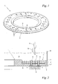
- Fig. 1 shows a perspective view of an inventively designed dosing 1 as part of a in Fig. 2 illustrated capsule filling device for the filling of capsules, not shown, with powder products.
- the metering disk 1 comprises an annular disk base body 3 and at least one thickness adaptation sheet 4 that can be detachably connected to the disk base body 3.
- the at least one thickness adaptation sheet 4 is screwed to the disk base body 3, for which purpose a multiplicity of in the Fig. 2 to 4 illustrated countersunk screws 5 is provided.
- the metering disk 1 is provided with a number of metering orifices 2.
- metering openings 2 are provided in a straight line along a secant to the circular contour.
- the six groups mentioned are positioned at equal angular intervals of 60 ° around the circumference. But it can also be a different number and arrangement of the metering 2 expedient.
- the metering openings 2 pass completely through the metering disk 1, ie run through the thickness adaptation sheet 4 and the disk base body 3 parallel to the axis of rotation of the metering disk 1 from top to bottom.
- Fig. 2 shows in a radial section an embodiment of the capsule filling device according to the invention, which is provided for the filling of capsules, not shown, with powder products.
- the capsule device comprises the metering disk 1 after Fig. 1 Here, only the radially outer region is shown.
- the dosing 1 is rotatably and height-fixed connected to a drive shaft, not shown, and is rotatably driven together with this about a vertical, perpendicular to the plane of the dosing 1 rotation axis by means of a stepping gear, also not shown in individual steps.
- a stepping gear also not shown in individual steps.
- the dosing disc 1 optionally also comprises further thickness adaptation plates 4 ', 4 ", which are stacked in a package and screwed to the disc base body 3 by means of the fastening screws 3.
- the screwing is carried out by means of countersunk screws 5 with countersunk heads 6, the countersunk heads 6 being flush with the surface lie with an outer, upper surface 7 of the uppermost thickness adjustment plate 4.
- the metering openings 2 which pass through from top to bottom through all the thickness adaptation plates 4, 4 ', 4 "and the disk base body 3, have longitudinal axes which run parallel to the rotation axis of the metering disk 1 or perpendicular to the plane of the metering disk 1.
- Each of the metering openings 2 of a single, in connection with Fig. 1 described group of metering 2 is associated with a vertical plunger 12, in which case only one metering opening 2 and an associated plunger 12th are shown.
- the cross-sectional contour of the plunger 12 corresponds exactly to the cross-sectional contour of the respective metering opening 2.
- the group of plungers 12 is lowered in operation from top to bottom in the associated group of metering 2 cyclically according to an arrow 13 and moved out again upwards.
- the capsule filling device further comprises a closure element for the lower ends of the metering orifices 2.
- the closure element like the metering disk 1, is held in the capsule filling device in a height-resistant manner, but does not execute its own rotation during operation.
- the closure element is formed as a stop ring 9, which partially revolves about the axis of rotation, in the form of a C-shaped ring segment on which the metering disk 1 rests at least approximately gap-free with the larger part of its metering openings 2 in the region of its associated lower ends. As a result, the corresponding metering openings 2 are closed in the vertical direction downwards.
- the powder bed 11 consists of a powder to be filled, granules or the like, for example in the form of a powdered medicament, dietary supplement or a comparable powder.
- this is pressed out of the powder bed 11 by means of the plunger 12 into the metering openings 2, the stop ring 9 preventing a push-through.
- the metered amount of the powder product is determined inter alia by the volume of the metering orifices 2, that is to say by their cross section and their axial length.
- An adaptation of the dosing can be done according to the invention by replacement and any combination of Dickenanpassungsblechen 4, 4 ', 4 ", whereby from the selected total thickness of the disc body 3 and the at least one thickness adjustment plate 4, 4', 4" a certain axial length of the metering 2 is set.
- the cross section of the metering orifices 2 does not change, so that the pressure stamps 2 adapted in their cross section do not have to be exchanged.
- the volume adaptation takes place solely by selecting a suitable axial length of the metering orifices 2 as a result of the selected combination of the disk base body 3 with at least one thickness adaptation sheet 4, 4 ', 4 " Fig. 2 It can also be deduced that several thickness adaptation plates 4, 4 ', 4 "with different thicknesses are used here by way of example, which permits a finely graduated adaptation of the total thickness and thus of the dosing volume, but it may also be expedient to use only one type of thickness adaptation plate 4. 4 ', 4 "to use with a certain thickness.
- Fig. 3 shows in a perspective exploded view of the dosing 1 after Fig. 1 with the disk base body 3, an exemplary selection of thickness adaptation plates 4, 4 ', 4 "and countersunk screws 5 for the detachable connection of the said parts It can be seen that all the thickness adaptation plates 4, 4', 4" are provided with a number of bores 15, 15 '. , 15 ", to which a corresponding number of holes 16 in the disc base body 3 corresponds All holes 15, 15 ', 15", 16 are aligned with each other and have the same, calibrated cross-section or diameter, so that they in the assembled state of Dosing disc ( Fig. 1 ) the aligned, continuous metering orifices 2 ( Fig. 2 ) form.
- the thickness adjustment plates 4, 4 ', 4 still holes for the passage of the countersunk screws 5, to which corresponding to the disc body 3 a corresponding number of threaded holes ( Fig. 2 ) are provided for screwing the countersunk screws 5.
- the uppermost thickness adaptation plate 4 provided in the stacking sequence is provided with countersinks 14.
- Fig. 4 shows in a cross-sectional view of the arrangement Fig. 3 , wherein like parts are identified by like reference numerals. It can be seen from the cross-sectional illustration shown that the disk base body 3 is provided with a receiving recess 8 for the thickness adaptation plates 4, 4 ', 4 " Fig. 2 . 3 and 4 As a result, the receiving recess 8 is adapted in its contour exactly to the contour of the thickness adaptation plates 4, 4 ', 4 ", ie likewise in the form of a closed circumferential circular ring outwardly bounded by an outer annular wall 17 and radially inwardly by an inner annular wall 18.
- the receiving recess 8 is open, so that the package of thickness adjustment plates 4, 4 ', 4 "in any suitable combination and number from above can be lowered into the receiving recess 8 and fastened there by means of the fastening screws 5.
- the outer annular wall 17 and the inner annular wall 18 are in the assembled state gap-free at the outer and inner edges of the Dickenanpassungsbleche 4, 4 ', 4 ", as shown in Fig. 2 is shown. Overall, this results in the assembled, in Fig. 2 shown state that is formed by the disc base body 3 and arranged on the upper side Dickenanpassungsbleche 4, 4 ', 4 ", a common, smooth, flat, annular gap-free circumferential surface 7, on which the powder bed 11 rests.
Landscapes
- Engineering & Computer Science (AREA)
- Health & Medical Sciences (AREA)
- Quality & Reliability (AREA)
- Mechanical Engineering (AREA)
- Pharmacology & Pharmacy (AREA)
- Medicinal Chemistry (AREA)
- Chemical & Material Sciences (AREA)
- Life Sciences & Earth Sciences (AREA)
- Animal Behavior & Ethology (AREA)
- General Health & Medical Sciences (AREA)
- Public Health (AREA)
- Veterinary Medicine (AREA)
- Basic Packing Technique (AREA)
Abstract
Description
- Die Erfindung betrifft eine Dosierscheibe einer Kapselfiilleinrichtung der im Oberbegriff des Anspruchs 1 angegebenen Gattung sowie eine Kapselfiilleinrichtung mit einer solchen Dosierscheibe.
- Für die Befüllung von Kapseln mit Pulverprodukten, also beispielsweise Pulver, Granulat, Pellets oder dergleichen in Form von Medikamenten, Nahrungsergänzungsmitteln oder dergleichen werden Kapselfiilleinrichtungen eingesetzt, wie sie beispielsweise aus dem Dokument
DE 296 20 828 U1 bekannt sind. Teil der dort beschriebenen Kapselfiilleinrichtung ist eine Dosierscheibe, die einen Scheibengrundkörper sowie in den Scheibengrundkörper auswechselbar eingesetzte Dosierbuchsen aufweist. In den genannten Dosierbuchsen sind Dosieröffnungen ausgebildet. Oberhalb der Dosierscheibe befindet sich ein Pulverbett. Druckstempel werden in die Dosieröffnungen der Dosierbuchsen abgesenkt, um innerhalb der Dosieröffnung eine volumetrische Dosierung des Pulverproduktes vorzunehmen, und um anschließend das dosierte Pulverprodukt nach unten durch die Dosieröffnungen hindurch in eine bereitgestellte, geöffnete Kapsel hinein zu drücken. - In dem genannten Dokument wird auf die Möglichkeit hingewiesen, die Dosierscheibe durch Austausch der Dosierbuchsen für eine Vielzahl von unterschiedlichen Durchmessern und/oder Längen der zu befüllenden Kapseln einsetzbar zu machen, ohne dass die Dosierscheibe selbst ausgetauscht werden muss.
- Sofern aufgabenbedingt der Durchmesser der Dosieröffnungen verändert werden soll, müssen sämtliche Dosierbuchsen und auch die im Durchmesser daran angepassten Druckstempel ausgetauscht werden. Noch problematischer ist eine Längenanpassung der Dosieröffnungen. Hierbei reicht es nicht, die Dosierbuchsen auszutauschen, da ansonsten die Höhenjustierung beispielsweise gegenüber einem unterhalb der Dosierscheibe angeordneten Stopfring nicht mehr stimmen würde. Es muss also entweder eine aufwendige Höhenjustage oder ein vollständiger Austausch der Dosierscheibe vorgenommen werden, was hinsichtlich der erforderlichen Teile und auch hinsichtlich des erforderlichen Umrüstaufwands einschließlich der damit verbundenen Stillstandszeiten kostenintensiv ist und die Produktivität beeinträchtigt.
- Der Erfindung liegt die Aufgabe zugrunde, eine gattungsgemäße Dosierscheibe derart weiterzubilden, dass eine vereinfachte Anpassung des Dosiervolumens möglich ist.
- Diese Aufgabe wird durch eine Dosierscheibe mit den Merkmalen des Anspruchs 1 gelöst.
- Der Erfindung liegt des Weiteren die Aufgabe zugrunde, eine Kapselfülleinrichtung für die Befüllung von Kapseln anzugeben, die in vereinfachter Weise für unterschiedliche Füllvolumen umgerüstet werden kann.
- Diese Aufgabe wird durch eine Kapselfülleinrichtung mit den Merkmalen des Anspruchs 9 gelöst.
- Nach der Erfindung ist vorgesehen, dass die Dosierscheibe einen Scheibengrundkörper und mindestens ein lösbar mit dem Scheibengrundkörper verbindbares Dickenanpassungsblech aufweist, wobei die Dosieröffnung den Scheibengrundkörper und das mindestens eine Dickenanpassungsblech durchgreift. Bevorzugt sind mehrere Dickenanpassungsbleche mit insbesondere unterschiedlicher Dicke vorgesehen. Hierdurch ist die Möglichkeit eröffnet, den Scheibengrundkörper nach Bedarf mit einem oder mehreren Dickenanpassungsblechen so zu kombinieren, dass sich die gewünschte Gesamtdicke und damit die gewünschte Gesamtlänge der Dosieröffnung einstellt. Dabei braucht der Scheibengrundkörper weder ausgetauscht noch in seiner Höhe verstellt werden. Vielmehr reicht es aus, das gewünschte Dosiervolumen allein durch Wahl bzw. Austausch von einem oder mehreren Dickenanpassungsblechen herbeizuführen.
- Es kann zweckmäßig sein, das mindestens eine Dickenanpassungsblech auf der Unterseite des Scheibengrundkörpers anzuordnen. Bevorzugt ist es aber auf dessen Oberseite angeordnet, so dass die Interaktion des fest montierten Scheibengrundkörpers mit darunter angeordneten weiteren Elementen wie ein Stopfring oder dergleichen nicht beeinträchtigt ist.
- Eine Möglichkeit besteht darin, die Dickenanpassungsbleche in Form von einzelnen Segmenten auszuführen. Vorteilhaft ist das Dickenanpassungsblech in Form eines ebenen, geschlossen umlaufenden Kreisringes ausgebildet. Die hierdurch gebildete geschlossene obere Oberfläche verhindert ein ungewünschtes Eindringen des Pulverproduktes in Spalte oder dergleichen. Außerdem bildet sich eine glatte, ebene Oberfläche aus, auf der das Pulverbett während des Dosiervorganges aufliegt und ohne störende Kanten leicht gehandhabt werden kann.
- Das Dickenanpassungsblech kann mit dem Scheibengrundkörper durch Klemmung oder in anderer geeigneter Weise lösbar befestigt werden. Bevorzugt ist hierfür eine Verschraubung vorgesehen. Insbesondere ist die Verschraubung mittels Senkkopfschrauben ausgeführt, wobei deren Senkköpfe flächenbündig mit einer äußeren Oberfläche des mindestens einen Dickenanpassungsblechs liegen. Bei einer entsprechenden Anzahl und Verteilung der Schrauben ist eine gleichmäßige Flächenpressung ohne Verwölbung der Dickenanpassungsbleche sichergestellt. Die Senkköpfe der eingelassenen Senkkopfschrauben führen zu keiner nennenswerten Unterbrechung der ansonsten glatten äußeren Oberfläche. Ein Austausch eines oder mehrerer Dickenanpassungsbleche kann ohne Spezialwerkzeug mit geringem Aufwand allein durch Lösen und Festziehen der genannten Verschraubung herbeigeführt werden.
- In vorteilhafter Weiterbildung ist der Scheibengrundkörper mit einer Aufnahmevertiefung für eine spaltfreie Aufnahme des mindestens einen Dickenanpassungsblechs versehen. Das Dickenanpassungsblech bzw. ein Paket von mehreren solcher Dickenanpassungsbleche ist spaltfrei in die Aufnahmevertiefung eingelassen, wodurch eine spaltfreie gemeinsame Oberfläche aus dem Scheibengrundkörper und dem obersten Dickenanpassungsblech gebildet wird. Unabhängig von der gewählten Dicke des Dickenanpassungsblechs bzw. eines Pakets davon ist eine störungsfreie Handhabung des Pulvers sichergestellt.
- Ein Ausführungsbeispiel der Erfindung ist nachstehend anhand der Zeichnung näher beschrieben. Es zeigen:
- Fig. 1
- in einer perspektivischen Ansicht eine erfindungsgemäß ausgeführte Dosierscheibe mit einem Scheibengrundkörper und einem darin eingelassenen Paket aus Dickenanpassungsblechen;
- Fig. 2
- in einem Radialschnitt eine erfindungsgemäß ausgeführte Kapselfülleinrichtung mit einer Dosierscheibe nach
Fig. 1 ; - Fig. 3
- in einer Explosionsdarstellung die Dosierscheibe nach
Fig. 1 mit Einzelheiten zur Ausgestaltung eines Paketes von Dickenanpassungsblechen mit zugehörigen Befestigungsschrauben; - Fig. 4
- eine Querschnittsdarstellung der Anordnung nach
Fig. 3 mit weiteren Einzelheiten zur Ausgestaltung des Scheibengrundkörpers mit einer Aufnahmevertiefung für das Paket von Dickenanpassungsblechen. -
Fig. 1 zeigt in einer perspektivischen Ansicht eine erfindungsgemäß ausgeführte Dosierscheibe 1 als Teil einer inFig. 2 dargestellten Kapselfülleinrichtung für die Befüllung von nicht dargestellten Kapseln mit Pulverprodukten. Die Dosierscheibe 1 umfasst einen kreisringförmigen Scheibengrundkörper 3 und mindestens ein lösbar mit dem Scheibengrundkörper 3 verbindbares Dickenanpassungsblech 4. Das mindestens eine Dickenanpassungsblech 4 ist mit dem Scheibengrundkörper 3 verschraubt, wozu eine Vielzahl von in denFig. 2 bis 4 dargestellten Senkkopfschrauben 5 vorgesehen ist. Im,montierten Zustand nachFig. 1 ist von den genannten Senkkopfschrauben 5 nur die entsprechende Anzahl von Senkköpfen 6 erkennbar. Die Dosierscheibe 1 ist mit einer Anzahl von Dosieröffnungen 2 versehen. Im gezeigten Ausführungsbeispiel sind sechs Gruppen mit jeweils zwölf Dosieröffnungen 2 vorgesehen. Jeweils eine Gruppe von Dosieröffnungen 2 ist in einer geraden Reihe entlang einer Sekante zur Kreisringkontur angeordnet. Die genannten sechs Gruppen sind in gleichmäßigen Winkelabständen von 60° über den Umfang positioniert. Es kann aber auch eine andere Anzahl und Anordnung der Dosieröffnungen 2 zweckmäßig sein. In jedem Falle durchgreifen die Dosieröffnungen 2 die Dosierscheibe 1 vollständig, verlaufen also durch das Dickenanpassungsblech 4 und den Scheibengrundkörper 3 parallel zur Rotationsachse der Dosierscheibe 1 von oben nach unten. -
Fig. 2 zeigt in einem Radialschnitt ein Ausführungsbeispiel der erfindungsgemäßen Kapselfülleinrichtung, welche für die Befüllung von nicht dargestellten Kapseln mit Pulverprodukten vorgesehen ist. Die Kapselfiilleinrichtung umfasst die Dosierscheibe 1 nachFig. 1 , wobei hier nur der radial äußere Bereich gezeigt ist. Die Dosierscheibe 1 ist drehfest und höhenfest mit einer nicht dargestellten Antriebswelle verbunden, und ist gemeinsam mit dieser um eine vertikale, senkrecht zur Ebene der Dosierscheibe 1 stehende Drehachse mittels eines ebenfalls nicht dargestellten Schrittschaltgetriebes in einzelnen Drehschritten drehend antreibbar. Neben dem Scheibengrundkörper 3 und dem obersten, inFig. 1 erkennbaren Dickenanpassungsblech 4 umfasst die Dosierscheibe 1 optional noch weitere Dickenanpassungsbleche 4', 4", die zu einem Paket übereinander gestapelt und mittels der Befestigungsschrauben mit dem Scheibengrundkörper 3 verschraubt sind. Die Verschraubung ist mittels Senkkopfschrauben 5 mit Senkköpfen 6 ausgeführt, wobei die Senkköpfe 6 flächenbündig mit einer äußeren, oberen Oberfläche 7 des obersten Dickenanpassungsblechs 4 liegen. - Die von oben nach unten durch sämtliche Dickenanpassungsbleche 4, 4', 4" und den Scheibengrundkörper 3 durchgehenden Dosieröffnungen 2 weisen Längsachsen auf, die parallel zur Drehachse der Dosierscheibe 1 bzw. senkrecht zur Ebene der Dosierscheibe 1 verlaufen. Jeder der Dosieröffnungen 2 einer einzelnen, im Zusammenhang mit
Fig. 1 beschriebenen Gruppe von Dosieröffnungen 2 ist je ein vertikaler Druckstempel 12 zugeordnet, wobei hier nur eine Dosieröffnung 2 und ein zugeordneter Druckstempel 12 dargestellt sind. Die Querschnittskontur der Druckstempel 12 entspricht exakt der Querschnittskontur der jeweiligen Dosieröffnung 2. Die Gruppe von Druckstempeln 12 wird im Betrieb von oben nach unten in die zugeordnete Gruppe von Dosieröffnungen 2 zyklisch entsprechend einem Pfeil 13 abgesenkt und nach oben wieder herausgefahren. - Die Kapselfülleinrichtung umfasst des Weiteren ein Verschlusselement für die unteren Enden der Dosieröffnungen 2. Das Verschlusselement ist ebenso wie die Dosierscheibe 1 höhenfest in der Kapselfülleinrichtung gehalten, ohne aber im Betrieb eine Eigendrehung auszuführen. Im gezeigten Ausführungsbeispiel ist das Verschlusselement als um die Drehachse teilweise umlaufender Stopfring 9 in Form eines C-förmigen Ringsegmentes ausgebildet, auf dem die Dosierscheibe 1 mit dem größeren Teil ihrer Dosieröffnungen 2 im Bereich ihrer zugeordneten unteren Enden zumindest näherungsweise spaltfrei aufliegt. Hierdurch werden die entsprechenden Dosieröffnungen 2 in vertikaler Richtung nach unten hin verschlossen.
- Oberhalb der Dosierscheibe 1 befindet sich im Betrieb ein Pulverbett 11, welches infolge seiner Gewichtskraft auf der oberen Seite der Dosierscheibe 1 aufliegt und radial nach außen durch eine umlaufende Einfassung 10 gehalten ist. Das Pulverbett 11 besteht aus einem abzufüllenden Pulver, Granulat oder dergleichen beispielsweise in Form eines pulverigen Medikamentes, Nahrungsergänzungsmittels oder eines vergleichbaren Pulvers. Für die volumetrische Dosierung des Pulvers wird dieses aus dem Pulverbett 11 heraus mittels der Druckstempel 12 in die Dosieröffnungen 2 hineingedrückt, wobei der Stopfring 9 ein Durchdrücken verhindert. Durch das Volumen der Dosieröffnungen 2, Absenkdruck und -weg der Druckstempel 12 und auch durch die Beschaffenheit des Pulvers wird hierdurch ein in Volumen und Masse exakt abgemessenes Pulverprodukt in den Dosieröffnungen 2 bereitgestellt. Dieses in vorstehender Weise volumetrisch dosierte Pulverprodukt wird durch Drehung der Dosierscheibe 1 um ihre Drehachse entlang des geschlossenen Teils des feststehenden C-förmigen Stopfringes 9 verfahren, bis es die offene Stelle des C-förmigen Stopfringes erreicht. Dort ist eine nicht dargestellte Übergabestation angeordnet, die ebenso wie der Stopfring 9 in ihrer räumlichen Lage fixiert ist. In der genannten Übergabestation werden offene Kapselhälften bereitgehalten, in die das zuvor dosierte Pulverprodukt mittels der Druckstempel 12 aus den Dosieröffnungen 2 heraus eingedrückt wird.
- Wie oben schon erwähnt, wird die Dosiermenge des Pulverproduktes unter anderem durch das Volumen der Dosieröffnungen 2 bestimmt, also durch deren Querschnitt und deren axiale Länge. Eine Anpassung der Dosiermenge kann nach der Erfindung durch Austausch und beliebige Kombination von Dickenanpassungsblechen 4, 4', 4" erfolgen, wodurch aus der gewählten Gesamtdicke des Scheibengrundkörpers 3 und des mindestens einen Dickenanpassungsblechs 4, 4', 4" eine bestimmte axiale Länge der Dosieröffnungen 2 eingestellt wird. Der Querschnitt der Dosieröffnungen 2 ändert sich nicht, so dass auch die in ihrem Querschnitt daran angepassten Druckstempel 2 nicht ausgetauscht werden müssen. Die Volumenanpassung erfolgt allein durch Wahl einer geeigneten axialen Länge der Dosieröffnungen 2 als Folge der gewählten Kombination des Scheibengrundkörpers 3 mit mindestens einem Dickenanpassungsblech 4, 4', 4". Der Darstellung nach
Fig. 2 ist noch entnehmbar, dass hier beispielhaft mehrere Dickenanpassungsbleche 4, 4', 4" mit unterschiedlicher Dicke zum Einsatz kommen, was eine fein abgestufte Anpassung der Gesamtdicke und damit des Dosiervolumens ermöglicht. Es kann aber auch zweckmäßig sein, nur eine Sorte von Dickenanpassungsblechen 4, 4', 4" mit einer bestimmten Dicke einzusetzen. -
Fig. 3 zeigt in einer perspektivischen Explosionsdarstellung die Dosierscheibe 1 nachFig. 1 mit dem Scheibengrundkörper 3, einer beispielhaften Auswahl von Dickenanpassungsblechen 4, 4', 4" sowie Senkkopfschrauben 5 zur lösbaren Verbindung der genannten Teile. Es ist erkennbar, dass sämtliche Dickenanpassungsbleche 4, 4', 4" mit einer Anzahl von Bohrungen 15, 15', 15" versehen ist, wozu eine entsprechende Anzahl von Bohrungen 16 im Scheibengrundkörper 3 korrespondiert. Sämtliche Bohrungen 15, 15', 15", 16 fluchten zueinander und weisen den gleichen, kalibrierten Querschnitt bzw. Durchmesser auf, so dass sie im montierten Zustand der Dosierscheibe (Fig. 1 ) die fluchtenden, durchgehenden Dosieröffnungen 2 (Fig. 2 ) bilden. - Darüber hinaus weisen die Dickenanpassungsbleche 4, 4', 4" noch Bohrungen für die Hindurchführung der Senkkopfschrauben 5 auf, zu denen korrespondierend im Scheibengrundkörper 3 eine entsprechende Anzahl von Gewindebohrungen (
Fig. 2 ) zum Eindrehen der Senkkopfschrauben 5 vorgesehen sind. Im Bereich der letztgenannten Bohrungen ist das in der Stapelfolge oberste Dickenanpassungsblech 4 mit Senkungen 14 versehen. Diese nehmen entsprechend der Darstellung nachFig. 2 die Senkköpfe 6 der Senkkopfschrauben 5 in einer Weise auf, dass die oberen Stirnflächen der Senkköpfe 6 flächenbündig zur äußeren Oberfläche 7 des obersten Dickenanpassungsblechs 4 liegen. Schließlich ist inFig. 3 noch erkennbar, dass sämtliche Dickenanpassungsbleche 4, 4', 4" jeweils in Form eines ebenen, geschlossen umlaufenden Kreisringes ausgebildet sind. -
Fig. 4 zeigt in einer Querschnittsdarstellung die Anordnung nachFig. 3 , wobei gleiche Teile mit gleichen Bezugszeichen identifiziert sind. Der gezeigten Querschnittsdarstellung ist entnehmbar, dass der Scheibengrundkörper 3 mit einer Aufnahmevertiefung 8 für die Dickenanpassungsbleche 4, 4', 4" versehen ist. Aus der Zusammenschau derFig. 2 ,3 und 4 ergibt sich, dass die Aufnahmevertiefung 8 in ihrer Kontur exakt an die Kontur der Dickenanpassungsbleche 4, 4', 4" angepasst ist, also ebenfalls die Form eines geschlossenen umlaufenden Kreisringes aufweist. Hierzu ist die Aufnahmevertiefung 8 nach unten durch den Scheibengrundkörper 3 selbst, radial nach außen durch eine äußere Ringwand 17 und radial nach innen durch eine innere Ringwand 18 begrenzt. Nach oben hin ist die Aufnahmevertiefung 8 offen, so dass das Paket von Dickenanpassungsblechen 4, 4', 4" in beliebiger bzw. geeigneter Kombination und Anzahl von oben in die Aufnahmevertiefung 8 abgesenkt und dort mittels der Befestigungsschrauben 5 befestigt werden kann. Die äußere Ringwand 17 und die innere Ringwand 18 liegen im montierten Zustand spaltfrei an den Außen- und Innenkanten der Dickenanpassungsbleche 4, 4', 4" an, wie dies inFig. 2 dargestellt ist. Insgesamt ergibt sich daraus im montierten, inFig. 2 dargestellten Zustand, dass durch den Scheibengrundkörper 3 und die auf dessen Oberseite angeordneten Dickenanpassungsbleche 4, 4', 4", eine gemeinsame, glatte, ebene, kreisringförmig spaltfrei umlaufende Oberfläche 7 gebildet ist, auf der das Pulverbett 11 aufliegt.
Claims (10)
- Dosierscheibe (1) einer Kapselfülleinrichtung für die Befüllung von Kapseln mit Pulverprodukten, wobei die Dosierscheibe (1) eine Anzahl von Dosieröffnungen (2) aufweist,
dadurch gekennzeichnet, dass die Dosierscheibe (1) einen Scheibengrundkörper (3) und mindestens ein lösbar mit dem Scheibengrundkörper (3) verbindbares Dickenanpassungsblech (4, 4', 4") aufweist, wobei die Dosieröffnung (2) den Scheibengrundkörper (3) und das mindestens eine Dickenanpassungsblech (4, 4', 4") durchgreift. - Dosierscheibe nach Anspruch 1,
dadurch gekennzeichnet, dass mehrere Dickenanpassungsbleche (4, 4', 4") vorgesehen sind. - Dosierscheibe nach Anspruch 2,
dadurch gekennzeichnet, dass mehrere Dickenanpassungsbleche (4, 4', 4") mit unterschiedlicher Dicke vorgesehen sind. - Dosierscheibe nach einem der Ansprüche 1 bis 3,
dadurch gekennzeichnet, dass das mindestens eine Dickenanpassungsblech (4, 4', 4") auf der Oberseite des Scheibengrundkörpers (3) angeordnet ist. - Dosierscheibe nach einem der Ansprüche 1 bis 4,
dadurch gekennzeichnet, dass das Dickenanpassungsblech (4, 4', 4") in Form eines ebenen, geschlossen umlaufenden Kreisringes ausgebildet ist. - Dosierscheibe nach einem der Ansprüche 1 bis 5,
dadurch gekennzeichnet, dass das Dickenanpassungsblech (4, 4', 4") mit dem Scheibengrundkörper (3) verschraubt ist. - Dosierscheibe nach Anspruch 6,
dadurch gekennzeichnet, dass die Verschraubung mittels Senkkopfschrauben (5) mit Senkköpfen (6) ausgeführt ist, wobei die Senkköpfe (6) flächenbündig mit einer äußeren Oberfläche (7) des mindestens einen Dickenanpassungsblechs (4, 4', 4") liegen. - Dosierscheibe nach einem der Ansprüche 1 bis 7,
dadurch gekennzeichnet, dass der Scheibengrundkörper (3) mit einer Aufnahmevertiefung (8) für eine spaltfreie Aufnahme des mindestens einen Dickenanpassungsblechs (4, 4', 4") versehen ist. - Kapselfülleinrichtung für die Befüllung von Kapseln mit Pulverprodukten, umfassend eine Dosierscheibe (1) nach einem der Ansprüche 1 bis 8,
dadurch gekennzeichnet, dass die Dosierscheibe (1) höhenfest in der Kapselfiilleinrichtung montiert ist. - Kapselfülleinrichtung nach Anspruch 9,
dadurch gekennzeichnet, dass ein unterhalb der Dosierscheibe (1) angeordneter Stopfring (9) höhenfest in der Kapselfiilleinrichtung montiert ist.
Priority Applications (1)
| Application Number | Priority Date | Filing Date | Title |
|---|---|---|---|
| SI201330284A SI2674144T1 (sl) | 2012-06-16 | 2013-06-05 | Dozirni disk in naprava za polnjenje kapsul z dozirnim diskom |
Applications Claiming Priority (1)
| Application Number | Priority Date | Filing Date | Title |
|---|---|---|---|
| DE202012005898U DE202012005898U1 (de) | 2012-06-16 | 2012-06-16 | Dosierscheibe und Kapselfülleinrichtung mit Dosierscheibe |
Publications (2)
| Publication Number | Publication Date |
|---|---|
| EP2674144A1 true EP2674144A1 (de) | 2013-12-18 |
| EP2674144B1 EP2674144B1 (de) | 2016-08-10 |
Family
ID=46635617
Family Applications (1)
| Application Number | Title | Priority Date | Filing Date |
|---|---|---|---|
| EP13002884.8A Active EP2674144B1 (de) | 2012-06-16 | 2013-06-05 | Dosierscheibe und kapselfülleinrichtung mit dosierscheibe |
Country Status (8)
| Country | Link |
|---|---|
| US (1) | US20130333801A1 (de) |
| EP (1) | EP2674144B1 (de) |
| CA (1) | CA2818246A1 (de) |
| DE (1) | DE202012005898U1 (de) |
| DK (1) | DK2674144T3 (de) |
| ES (1) | ES2602292T3 (de) |
| PL (1) | PL2674144T3 (de) |
| SI (1) | SI2674144T1 (de) |
Cited By (2)
| Publication number | Priority date | Publication date | Assignee | Title |
|---|---|---|---|---|
| CN104873397A (zh) * | 2015-05-12 | 2015-09-02 | 绍兴海邦药业有限公司 | 一种螺杆定量胶囊自动填充装置 |
| CN104921948A (zh) * | 2015-05-12 | 2015-09-23 | 成都中牧生物药业有限公司 | 一种用于实现旋转灌装胶囊的转盘结构 |
Families Citing this family (3)
| Publication number | Priority date | Publication date | Assignee | Title |
|---|---|---|---|---|
| CN103893015B (zh) * | 2014-02-15 | 2017-04-05 | 四川光大制药有限公司 | 一种新型胶囊填充机计量盘 |
| US10071021B2 (en) * | 2015-05-19 | 2018-09-11 | Maxocap Corporation | Capsule filling systems and methods of using a capsule filling system |
| DE102018202602A1 (de) | 2018-02-21 | 2019-08-22 | Robert Bosch Gmbh | Dosierscheibe für eine Kapselfüllanlage und Kapselfüllanlage |
Citations (3)
| Publication number | Priority date | Publication date | Assignee | Title |
|---|---|---|---|---|
| GB1027780A (en) * | 1964-03-06 | 1966-04-27 | Glassman Jacob A | Method of producing peroral capsule |
| DE29620828U1 (de) * | 1996-11-30 | 1997-05-28 | Notter GmbH Werkzeugbau, 75248 Ölbronn-Dürrn | Dosierscheibe für eine Kapselfüllanlage |
| DE202011108334U1 (de) * | 2011-11-25 | 2012-01-03 | Harro Höfliger Verpackungsmaschinen GmbH | Kapselfülleinrichtung für die Befüllung von Kapseln mit Pulverprodukten |
Family Cites Families (31)
| Publication number | Priority date | Publication date | Assignee | Title |
|---|---|---|---|---|
| US2472092A (en) * | 1942-04-08 | 1949-06-07 | Alvin A Campbell | Dispensing and measuring device |
| US3324902A (en) * | 1965-05-26 | 1967-06-13 | Bartelt Engineering Co Inc | Method of filling capsules |
| US4733680A (en) * | 1986-05-19 | 1988-03-29 | Mosier Larry G | Dispenser apparatus |
| JPH0620919B2 (ja) * | 1987-06-18 | 1994-03-23 | 日本エランコ株式会社 | 硬質カプセルへの粒状物充填方法およびその装置 |
| US4880150A (en) * | 1988-05-27 | 1989-11-14 | Spee-Dee Packaging Machinery Inc. | Filling machine for dispensing particulate material |
| US5320146A (en) * | 1993-01-26 | 1994-06-14 | R. A. Jones & Co. Inc. | Volumetric feeder with belt gate |
| US5388572A (en) * | 1993-10-26 | 1995-02-14 | Tenax Corporation (A Connecticut Corp.) | Dry powder medicament inhalator having an inhalation-activated piston to aerosolize dose and deliver same |
| GB9523555D0 (en) * | 1995-11-17 | 1996-01-17 | Cambridge Consultants | Filling containers with particulate material |
| DE19651237A1 (de) * | 1996-12-10 | 1998-06-18 | Bosch Gmbh Robert | Vorrichtung zum Dosieren und Abgeben von Pulver in Hartgelatinekapseln od. dgl. |
| US5934573A (en) * | 1997-03-07 | 1999-08-10 | Restaurant Technology, Inc. | Measuring dispenser-spreader and method |
| EP0979682A1 (de) * | 1998-08-13 | 2000-02-16 | B a r m a g AG | Pulverdosiereinrichtung mit Dosierscheibe |
| IT1316684B1 (it) * | 1999-03-13 | 2003-04-24 | Bosch Gmbh Robert | Supporto delle parti di capsule in una macchina di caricamento e dichiusura per capsule in due parti |
| DE10027008B4 (de) * | 2000-05-31 | 2016-12-29 | Robert Bosch Gmbh | Dosiervorrichtung |
| US6814111B1 (en) * | 2002-04-10 | 2004-11-09 | R.A. Jones & Co. Inc. | Adjustable volume side discharge feeder |
| AU2002320775A1 (en) * | 2002-07-05 | 2004-02-25 | Gaspardo Seminatrici S.P.A. | A volumetric metering device for the metered delivery of granular and powdery materials, particularly for machines for distributing the said materials |
| DE10354003A1 (de) * | 2003-11-19 | 2005-06-23 | Braun Gmbh | Dosiervorrichtung für pulver- oder flockenförmiges oder feinkörniges Dosiergut, vorzugsweise Kaffee-,Milch- oder Kakaopulver |
| WO2006036835A2 (en) * | 2004-09-24 | 2006-04-06 | Robert Kinzie | Programmable dispensing apparatus |
| US20070228083A1 (en) * | 2004-09-30 | 2007-10-04 | Catani Steven J | Apparatus and method for dispensing precisely controlled amounts of powdered material |
| US7536843B2 (en) * | 2006-01-23 | 2009-05-26 | Astrazeneca Ab | Method and system for dosing a pharmaceutical sample in a packaging machine |
| IL177096A0 (en) * | 2006-07-26 | 2006-12-10 | Strauss Elite Ltd | Dispenser for particulate material |
| US20080202532A1 (en) * | 2007-02-28 | 2008-08-28 | Gary Wygal | Method for portioning and depositing ground tobacco into containers |
| EP2170282A4 (de) * | 2007-06-27 | 2014-11-05 | Hanmi Pharm Ind Co Ltd | Verfahren zur herstellung einer schnell zerfallenden formulierung zur oralen verabreichung und gerät zur herstellung und verpackung der formulierung |
| US7784244B2 (en) * | 2007-08-13 | 2010-08-31 | Mts Medication Technologies, Inc. | High speed automated filling of solid pharmaceutical product packaging via a conveyor system |
| WO2009029026A1 (en) * | 2007-08-24 | 2009-03-05 | Astrazeneca Ab | A method for dosing and providing powder in a powder provider, such a powder provider device and an apparatus for producing packs |
| NZ590618A (en) * | 2008-08-14 | 2012-10-26 | Astrazeneca Ab | Dosing device and method for filling a cavity |
| CA2732842C (en) * | 2008-09-26 | 2018-01-09 | Oriel Therapeutics, Inc. | Inhalers with airway disks having discrete airway channels and related disks and methods |
| US20110284573A1 (en) * | 2008-12-17 | 2011-11-24 | Allan Dagsland | Method of providing a target dose, powder provider device and its use |
| EP2462024B1 (de) * | 2009-08-06 | 2014-01-15 | Harro Höfliger Verpackungsmaschinen GmbH | Füllanordnung zum dosieren von pulver und verfahren zum betrieb einer solchen füllanordnung |
| US8720497B2 (en) * | 2010-02-19 | 2014-05-13 | Oriel Therapeutics, Inc. | Direct fill dry powder systems with dosing heads configured for on/off controlled flow |
| EP2603190A4 (de) * | 2010-08-09 | 2015-04-29 | Kremer S Urban Llc | Zuführvorrichtung für minitabletten |
| TWM429474U (en) * | 2012-01-30 | 2012-05-21 | Univ Nat Taiwan | Improved capsule filler |
-
2012
- 2012-06-16 DE DE202012005898U patent/DE202012005898U1/de not_active Expired - Lifetime
-
2013
- 2013-06-05 ES ES13002884.8T patent/ES2602292T3/es active Active
- 2013-06-05 PL PL13002884T patent/PL2674144T3/pl unknown
- 2013-06-05 SI SI201330284A patent/SI2674144T1/sl unknown
- 2013-06-05 US US13/910,407 patent/US20130333801A1/en not_active Abandoned
- 2013-06-05 DK DK13002884.8T patent/DK2674144T3/en active
- 2013-06-05 EP EP13002884.8A patent/EP2674144B1/de active Active
- 2013-06-07 CA CA2818246A patent/CA2818246A1/en not_active Abandoned
Patent Citations (3)
| Publication number | Priority date | Publication date | Assignee | Title |
|---|---|---|---|---|
| GB1027780A (en) * | 1964-03-06 | 1966-04-27 | Glassman Jacob A | Method of producing peroral capsule |
| DE29620828U1 (de) * | 1996-11-30 | 1997-05-28 | Notter GmbH Werkzeugbau, 75248 Ölbronn-Dürrn | Dosierscheibe für eine Kapselfüllanlage |
| DE202011108334U1 (de) * | 2011-11-25 | 2012-01-03 | Harro Höfliger Verpackungsmaschinen GmbH | Kapselfülleinrichtung für die Befüllung von Kapseln mit Pulverprodukten |
Cited By (2)
| Publication number | Priority date | Publication date | Assignee | Title |
|---|---|---|---|---|
| CN104873397A (zh) * | 2015-05-12 | 2015-09-02 | 绍兴海邦药业有限公司 | 一种螺杆定量胶囊自动填充装置 |
| CN104921948A (zh) * | 2015-05-12 | 2015-09-23 | 成都中牧生物药业有限公司 | 一种用于实现旋转灌装胶囊的转盘结构 |
Also Published As
| Publication number | Publication date |
|---|---|
| SI2674144T1 (sl) | 2016-11-30 |
| CA2818246A1 (en) | 2013-12-16 |
| DE202012005898U1 (de) | 2012-07-09 |
| EP2674144B1 (de) | 2016-08-10 |
| ES2602292T3 (es) | 2017-02-20 |
| PL2674144T3 (pl) | 2017-01-31 |
| US20130333801A1 (en) | 2013-12-19 |
| DK2674144T3 (en) | 2016-11-07 |
Similar Documents
| Publication | Publication Date | Title |
|---|---|---|
| DE3228161C1 (de) | Beschickungseinrichtung zum Zufuehren von Kunststoffgranulat in eine Spritzgiesseinheit | |
| EP2674144B1 (de) | Dosierscheibe und kapselfülleinrichtung mit dosierscheibe | |
| EP2678646B1 (de) | Vorrichtung zum dosieren von pulverförmigem füllgut | |
| DE4200701B4 (de) | Maschine zum Dosieren pulverförmiger Pharmazeutika | |
| WO2007039612A1 (de) | Dosiereinrichtung für pulver- oder pastenförmige substanzen | |
| EP3595973A1 (de) | System mit alternierender füllung von behältern und verfahren hierzu | |
| DE102014210234A1 (de) | Vorrichtung zum Herstellen von Beutelpackungen | |
| EP0099980A1 (de) | Vorrichtung zur Bildung von Tabak-Portionen | |
| EP0602593B1 (de) | Einrichtung zum Beschneiden von flächigen Erzeugnissen, insbesondere mehrblättrigen Druckerzeugnissen | |
| DE102014201518A1 (de) | Teigteilmaschine | |
| DE3630077C2 (de) | ||
| EP0898155B1 (de) | Zufuhrvorrichtung für ein rieselfähiges Aufgabegut in eine Dosiervorrichtung | |
| EP1764173B1 (de) | Vorrichtung zum Herstellen eines Formteils | |
| DE1141937B (de) | Vorrichtung zum Gruppieren von liegend aufeinandergestapelten Biscuits | |
| DE2001715C3 (de) | Streugerät | |
| DE202011108334U1 (de) | Kapselfülleinrichtung für die Befüllung von Kapseln mit Pulverprodukten | |
| EP2650138B1 (de) | Buchform- und Pressmaschine | |
| AT167170B (de) | Vorrichtung zur geregelten Ausgabe von lose geschüttetem Kleinstückgut | |
| DE19750074C1 (de) | Dribbeleinrichtung für Trockenfutter | |
| EP0903308A1 (de) | Zellenrad zur Uebergabe von Gegenständen von einem ersten Fördermittel an ein zweites Fördermittel | |
| DE2265251C3 (de) | Verwendung einer Druckgießform für Druckgießmaschinen sowie Druckgießform zur Durchführung der Verwendung | |
| AT13119U1 (de) | Portioniereinheit für Teigteilmaschinen | |
| DE1023191B (de) | Verfahren und Vorrichtung zum Herstellen ueberzogener Tabletten | |
| DE3338395C2 (de) | ||
| DE1801340C (de) | Selbsttätige Schraubvorrichtung |
Legal Events
| Date | Code | Title | Description |
|---|---|---|---|
| PUAI | Public reference made under article 153(3) epc to a published international application that has entered the european phase |
Free format text: ORIGINAL CODE: 0009012 |
|
| AK | Designated contracting states |
Kind code of ref document: A1 Designated state(s): AL AT BE BG CH CY CZ DE DK EE ES FI FR GB GR HR HU IE IS IT LI LT LU LV MC MK MT NL NO PL PT RO RS SE SI SK SM TR |
|
| AX | Request for extension of the european patent |
Extension state: BA ME |
|
| 17P | Request for examination filed |
Effective date: 20140313 |
|
| RBV | Designated contracting states (corrected) |
Designated state(s): AL AT BE BG CH CY CZ DE DK EE ES FI FR GB GR HR HU IE IS IT LI LT LU LV MC MK MT NL NO PL PT RO RS SE SI SK SM TR |
|
| GRAP | Despatch of communication of intention to grant a patent |
Free format text: ORIGINAL CODE: EPIDOSNIGR1 |
|
| INTG | Intention to grant announced |
Effective date: 20160229 |
|
| GRAS | Grant fee paid |
Free format text: ORIGINAL CODE: EPIDOSNIGR3 |
|
| GRAA | (expected) grant |
Free format text: ORIGINAL CODE: 0009210 |
|
| AK | Designated contracting states |
Kind code of ref document: B1 Designated state(s): AL AT BE BG CH CY CZ DE DK EE ES FI FR GB GR HR HU IE IS IT LI LT LU LV MC MK MT NL NO PL PT RO RS SE SI SK SM TR |
|
| REG | Reference to a national code |
Ref country code: GB Ref legal event code: FG4D Free format text: NOT ENGLISH |
|
| REG | Reference to a national code |
Ref country code: CH Ref legal event code: EP Ref country code: AT Ref legal event code: REF Ref document number: 818292 Country of ref document: AT Kind code of ref document: T Effective date: 20160815 |
|
| REG | Reference to a national code |
Ref country code: IE Ref legal event code: FG4D Free format text: LANGUAGE OF EP DOCUMENT: GERMAN |
|
| REG | Reference to a national code |
Ref country code: DE Ref legal event code: R096 Ref document number: 502013003984 Country of ref document: DE |
|
| REG | Reference to a national code |
Ref country code: CH Ref legal event code: NV Representative=s name: ISLER AND PEDRAZZINI AG, CH |
|
| REG | Reference to a national code |
Ref country code: DK Ref legal event code: T3 Effective date: 20161104 |
|
| REG | Reference to a national code |
Ref country code: SE Ref legal event code: TRGR |
|
| REG | Reference to a national code |
Ref country code: LT Ref legal event code: MG4D |
|
| REG | Reference to a national code |
Ref country code: NL Ref legal event code: MP Effective date: 20160810 |
|
| PG25 | Lapsed in a contracting state [announced via postgrant information from national office to epo] |
Ref country code: HR Free format text: LAPSE BECAUSE OF FAILURE TO SUBMIT A TRANSLATION OF THE DESCRIPTION OR TO PAY THE FEE WITHIN THE PRESCRIBED TIME-LIMIT Effective date: 20160810 Ref country code: NL Free format text: LAPSE BECAUSE OF FAILURE TO SUBMIT A TRANSLATION OF THE DESCRIPTION OR TO PAY THE FEE WITHIN THE PRESCRIBED TIME-LIMIT Effective date: 20160810 Ref country code: IS Free format text: LAPSE BECAUSE OF FAILURE TO SUBMIT A TRANSLATION OF THE DESCRIPTION OR TO PAY THE FEE WITHIN THE PRESCRIBED TIME-LIMIT Effective date: 20161210 Ref country code: RS Free format text: LAPSE BECAUSE OF FAILURE TO SUBMIT A TRANSLATION OF THE DESCRIPTION OR TO PAY THE FEE WITHIN THE PRESCRIBED TIME-LIMIT Effective date: 20160810 Ref country code: FI Free format text: LAPSE BECAUSE OF FAILURE TO SUBMIT A TRANSLATION OF THE DESCRIPTION OR TO PAY THE FEE WITHIN THE PRESCRIBED TIME-LIMIT Effective date: 20160810 Ref country code: NO Free format text: LAPSE BECAUSE OF FAILURE TO SUBMIT A TRANSLATION OF THE DESCRIPTION OR TO PAY THE FEE WITHIN THE PRESCRIBED TIME-LIMIT Effective date: 20161110 Ref country code: LT Free format text: LAPSE BECAUSE OF FAILURE TO SUBMIT A TRANSLATION OF THE DESCRIPTION OR TO PAY THE FEE WITHIN THE PRESCRIBED TIME-LIMIT Effective date: 20160810 |
|
| REG | Reference to a national code |
Ref country code: ES Ref legal event code: FG2A Ref document number: 2602292 Country of ref document: ES Kind code of ref document: T3 Effective date: 20170220 |
|
| PG25 | Lapsed in a contracting state [announced via postgrant information from national office to epo] |
Ref country code: PT Free format text: LAPSE BECAUSE OF FAILURE TO SUBMIT A TRANSLATION OF THE DESCRIPTION OR TO PAY THE FEE WITHIN THE PRESCRIBED TIME-LIMIT Effective date: 20161212 Ref country code: GR Free format text: LAPSE BECAUSE OF FAILURE TO SUBMIT A TRANSLATION OF THE DESCRIPTION OR TO PAY THE FEE WITHIN THE PRESCRIBED TIME-LIMIT Effective date: 20161111 Ref country code: LV Free format text: LAPSE BECAUSE OF FAILURE TO SUBMIT A TRANSLATION OF THE DESCRIPTION OR TO PAY THE FEE WITHIN THE PRESCRIBED TIME-LIMIT Effective date: 20160810 |
|
| PG25 | Lapsed in a contracting state [announced via postgrant information from national office to epo] |
Ref country code: RO Free format text: LAPSE BECAUSE OF FAILURE TO SUBMIT A TRANSLATION OF THE DESCRIPTION OR TO PAY THE FEE WITHIN THE PRESCRIBED TIME-LIMIT Effective date: 20160810 Ref country code: EE Free format text: LAPSE BECAUSE OF FAILURE TO SUBMIT A TRANSLATION OF THE DESCRIPTION OR TO PAY THE FEE WITHIN THE PRESCRIBED TIME-LIMIT Effective date: 20160810 |
|
| REG | Reference to a national code |
Ref country code: DE Ref legal event code: R097 Ref document number: 502013003984 Country of ref document: DE |
|
| PG25 | Lapsed in a contracting state [announced via postgrant information from national office to epo] |
Ref country code: SM Free format text: LAPSE BECAUSE OF FAILURE TO SUBMIT A TRANSLATION OF THE DESCRIPTION OR TO PAY THE FEE WITHIN THE PRESCRIBED TIME-LIMIT Effective date: 20160810 Ref country code: SK Free format text: LAPSE BECAUSE OF FAILURE TO SUBMIT A TRANSLATION OF THE DESCRIPTION OR TO PAY THE FEE WITHIN THE PRESCRIBED TIME-LIMIT Effective date: 20160810 Ref country code: CZ Free format text: LAPSE BECAUSE OF FAILURE TO SUBMIT A TRANSLATION OF THE DESCRIPTION OR TO PAY THE FEE WITHIN THE PRESCRIBED TIME-LIMIT Effective date: 20160810 Ref country code: BG Free format text: LAPSE BECAUSE OF FAILURE TO SUBMIT A TRANSLATION OF THE DESCRIPTION OR TO PAY THE FEE WITHIN THE PRESCRIBED TIME-LIMIT Effective date: 20161110 |
|
| PLBE | No opposition filed within time limit |
Free format text: ORIGINAL CODE: 0009261 |
|
| STAA | Information on the status of an ep patent application or granted ep patent |
Free format text: STATUS: NO OPPOSITION FILED WITHIN TIME LIMIT |
|
| REG | Reference to a national code |
Ref country code: FR Ref legal event code: PLFP Year of fee payment: 5 |
|
| 26N | No opposition filed |
Effective date: 20170511 |
|
| PG25 | Lapsed in a contracting state [announced via postgrant information from national office to epo] |
Ref country code: MC Free format text: LAPSE BECAUSE OF FAILURE TO SUBMIT A TRANSLATION OF THE DESCRIPTION OR TO PAY THE FEE WITHIN THE PRESCRIBED TIME-LIMIT Effective date: 20160810 |
|
| PG25 | Lapsed in a contracting state [announced via postgrant information from national office to epo] |
Ref country code: LU Free format text: LAPSE BECAUSE OF NON-PAYMENT OF DUE FEES Effective date: 20170605 |
|
| REG | Reference to a national code |
Ref country code: BE Ref legal event code: MM Effective date: 20170630 |
|
| REG | Reference to a national code |
Ref country code: FR Ref legal event code: PLFP Year of fee payment: 6 |
|
| PG25 | Lapsed in a contracting state [announced via postgrant information from national office to epo] |
Ref country code: BE Free format text: LAPSE BECAUSE OF NON-PAYMENT OF DUE FEES Effective date: 20170630 |
|
| PG25 | Lapsed in a contracting state [announced via postgrant information from national office to epo] |
Ref country code: MT Free format text: LAPSE BECAUSE OF FAILURE TO SUBMIT A TRANSLATION OF THE DESCRIPTION OR TO PAY THE FEE WITHIN THE PRESCRIBED TIME-LIMIT Effective date: 20160810 |
|
| PG25 | Lapsed in a contracting state [announced via postgrant information from national office to epo] |
Ref country code: AL Free format text: LAPSE BECAUSE OF FAILURE TO SUBMIT A TRANSLATION OF THE DESCRIPTION OR TO PAY THE FEE WITHIN THE PRESCRIBED TIME-LIMIT Effective date: 20160810 |
|
| PG25 | Lapsed in a contracting state [announced via postgrant information from national office to epo] |
Ref country code: HU Free format text: LAPSE BECAUSE OF FAILURE TO SUBMIT A TRANSLATION OF THE DESCRIPTION OR TO PAY THE FEE WITHIN THE PRESCRIBED TIME-LIMIT; INVALID AB INITIO Effective date: 20130605 |
|
| REG | Reference to a national code |
Ref country code: AT Ref legal event code: MM01 Ref document number: 818292 Country of ref document: AT Kind code of ref document: T Effective date: 20180605 |
|
| PG25 | Lapsed in a contracting state [announced via postgrant information from national office to epo] |
Ref country code: CY Free format text: LAPSE BECAUSE OF NON-PAYMENT OF DUE FEES Effective date: 20160810 |
|
| PG25 | Lapsed in a contracting state [announced via postgrant information from national office to epo] |
Ref country code: MK Free format text: LAPSE BECAUSE OF FAILURE TO SUBMIT A TRANSLATION OF THE DESCRIPTION OR TO PAY THE FEE WITHIN THE PRESCRIBED TIME-LIMIT Effective date: 20160810 |
|
| PG25 | Lapsed in a contracting state [announced via postgrant information from national office to epo] |
Ref country code: AT Free format text: LAPSE BECAUSE OF NON-PAYMENT OF DUE FEES Effective date: 20180605 |
|
| PGFP | Annual fee paid to national office [announced via postgrant information from national office to epo] |
Ref country code: PL Payment date: 20250523 Year of fee payment: 13 Ref country code: DE Payment date: 20250618 Year of fee payment: 13 |
|
| PGFP | Annual fee paid to national office [announced via postgrant information from national office to epo] |
Ref country code: GB Payment date: 20250618 Year of fee payment: 13 Ref country code: DK Payment date: 20250625 Year of fee payment: 13 |
|
| PGFP | Annual fee paid to national office [announced via postgrant information from national office to epo] |
Ref country code: FR Payment date: 20250624 Year of fee payment: 13 |
|
| PGFP | Annual fee paid to national office [announced via postgrant information from national office to epo] |
Ref country code: TR Payment date: 20250527 Year of fee payment: 13 |
|
| PGFP | Annual fee paid to national office [announced via postgrant information from national office to epo] |
Ref country code: IE Payment date: 20250618 Year of fee payment: 13 |
|
| PGFP | Annual fee paid to national office [announced via postgrant information from national office to epo] |
Ref country code: SI Payment date: 20250522 Year of fee payment: 13 Ref country code: SE Payment date: 20250618 Year of fee payment: 13 |
|
| PGFP | Annual fee paid to national office [announced via postgrant information from national office to epo] |
Ref country code: ES Payment date: 20250728 Year of fee payment: 13 |
|
| PGFP | Annual fee paid to national office [announced via postgrant information from national office to epo] |
Ref country code: IT Payment date: 20250624 Year of fee payment: 13 |
|
| PGFP | Annual fee paid to national office [announced via postgrant information from national office to epo] |
Ref country code: CH Payment date: 20250701 Year of fee payment: 13 |