EP2673126B1 - Formwerkzeug zum hinterspritzen einer kunststofffolie mit einer kunststoffschmelze - Google Patents
Formwerkzeug zum hinterspritzen einer kunststofffolie mit einer kunststoffschmelze Download PDFInfo
- Publication number
- EP2673126B1 EP2673126B1 EP12703706.7A EP12703706A EP2673126B1 EP 2673126 B1 EP2673126 B1 EP 2673126B1 EP 12703706 A EP12703706 A EP 12703706A EP 2673126 B1 EP2673126 B1 EP 2673126B1
- Authority
- EP
- European Patent Office
- Prior art keywords
- moulding tool
- tool part
- plastic film
- region
- clamping surface
- Prior art date
- Legal status (The legal status is an assumption and is not a legal conclusion. Google has not performed a legal analysis and makes no representation as to the accuracy of the status listed.)
- Active
Links
- 239000002985 plastic film Substances 0.000 title claims description 107
- 229920006255 plastic film Polymers 0.000 title claims description 107
- 238000000465 moulding Methods 0.000 title claims description 76
- 239000004033 plastic Substances 0.000 title claims description 47
- 229920003023 plastic Polymers 0.000 title claims description 47
- 238000000034 method Methods 0.000 claims description 12
- 238000004519 manufacturing process Methods 0.000 claims description 9
- 238000002347 injection Methods 0.000 claims description 8
- 239000007924 injection Substances 0.000 claims description 8
- 230000008569 process Effects 0.000 claims description 5
- 238000007789 sealing Methods 0.000 claims description 4
- 238000001816 cooling Methods 0.000 claims description 3
- 238000003825 pressing Methods 0.000 claims description 2
- 230000000295 complement effect Effects 0.000 claims 1
- 239000010410 layer Substances 0.000 description 31
- 238000005034 decoration Methods 0.000 description 12
- 238000001746 injection moulding Methods 0.000 description 11
- 239000011888 foil Substances 0.000 description 9
- 230000000284 resting effect Effects 0.000 description 8
- 238000010137 moulding (plastic) Methods 0.000 description 7
- 239000004417 polycarbonate Substances 0.000 description 7
- 239000000463 material Substances 0.000 description 5
- 239000004743 Polypropylene Substances 0.000 description 4
- 239000012790 adhesive layer Substances 0.000 description 4
- 239000012994 photoredox catalyst Substances 0.000 description 4
- 229920001155 polypropylene Polymers 0.000 description 4
- 239000002184 metal Substances 0.000 description 3
- 229910052751 metal Inorganic materials 0.000 description 3
- 239000005060 rubber Substances 0.000 description 3
- 229920001169 thermoplastic Polymers 0.000 description 3
- 239000004416 thermosoftening plastic Substances 0.000 description 3
- 230000037303 wrinkles Effects 0.000 description 3
- 239000004793 Polystyrene Substances 0.000 description 2
- 239000011248 coating agent Substances 0.000 description 2
- 238000000576 coating method Methods 0.000 description 2
- 239000002131 composite material Substances 0.000 description 2
- 230000001419 dependent effect Effects 0.000 description 2
- 239000004413 injection moulding compound Substances 0.000 description 2
- 239000002346 layers by function Substances 0.000 description 2
- 230000004048 modification Effects 0.000 description 2
- 238000012986 modification Methods 0.000 description 2
- 239000002991 molded plastic Substances 0.000 description 2
- 230000003287 optical effect Effects 0.000 description 2
- 229920003229 poly(methyl methacrylate) Polymers 0.000 description 2
- 229920000515 polycarbonate Polymers 0.000 description 2
- 229920000139 polyethylene terephthalate Polymers 0.000 description 2
- 239000005020 polyethylene terephthalate Substances 0.000 description 2
- 239000004926 polymethyl methacrylate Substances 0.000 description 2
- -1 polypropylene Polymers 0.000 description 2
- 229920002223 polystyrene Polymers 0.000 description 2
- 239000011241 protective layer Substances 0.000 description 2
- 229910001369 Brass Inorganic materials 0.000 description 1
- RYGMFSIKBFXOCR-UHFFFAOYSA-N Copper Chemical compound [Cu] RYGMFSIKBFXOCR-UHFFFAOYSA-N 0.000 description 1
- 239000004809 Teflon Substances 0.000 description 1
- 229920006362 Teflon® Polymers 0.000 description 1
- 230000009471 action Effects 0.000 description 1
- 239000002318 adhesion promoter Substances 0.000 description 1
- 239000011127 biaxially oriented polypropylene Substances 0.000 description 1
- 229920006378 biaxially oriented polypropylene Polymers 0.000 description 1
- 230000015572 biosynthetic process Effects 0.000 description 1
- 239000010951 brass Substances 0.000 description 1
- 229920001940 conductive polymer Polymers 0.000 description 1
- 238000010276 construction Methods 0.000 description 1
- 229910052802 copper Inorganic materials 0.000 description 1
- 239000010949 copper Substances 0.000 description 1
- 238000009472 formulation Methods 0.000 description 1
- 230000009477 glass transition Effects 0.000 description 1
- 239000004922 lacquer Substances 0.000 description 1
- 230000013011 mating Effects 0.000 description 1
- 239000000203 mixture Substances 0.000 description 1
- 239000012778 molding material Substances 0.000 description 1
- 230000005693 optoelectronics Effects 0.000 description 1
- 239000003973 paint Substances 0.000 description 1
- 230000002093 peripheral effect Effects 0.000 description 1
- 229920001296 polysiloxane Polymers 0.000 description 1
- 229920000915 polyvinyl chloride Polymers 0.000 description 1
- 239000004800 polyvinyl chloride Substances 0.000 description 1
- 230000000717 retained effect Effects 0.000 description 1
- 239000002356 single layer Substances 0.000 description 1
- 239000007779 soft material Substances 0.000 description 1
- 239000000243 solution Substances 0.000 description 1
- 230000032258 transport Effects 0.000 description 1
Images


Classifications
-
- B—PERFORMING OPERATIONS; TRANSPORTING
- B29—WORKING OF PLASTICS; WORKING OF SUBSTANCES IN A PLASTIC STATE IN GENERAL
- B29C—SHAPING OR JOINING OF PLASTICS; SHAPING OF MATERIAL IN A PLASTIC STATE, NOT OTHERWISE PROVIDED FOR; AFTER-TREATMENT OF THE SHAPED PRODUCTS, e.g. REPAIRING
- B29C45/00—Injection moulding, i.e. forcing the required volume of moulding material through a nozzle into a closed mould; Apparatus therefor
- B29C45/14—Injection moulding, i.e. forcing the required volume of moulding material through a nozzle into a closed mould; Apparatus therefor incorporating preformed parts or layers, e.g. injection moulding around inserts or for coating articles
- B29C45/1418—Injection moulding, i.e. forcing the required volume of moulding material through a nozzle into a closed mould; Apparatus therefor incorporating preformed parts or layers, e.g. injection moulding around inserts or for coating articles the inserts being deformed or preformed, e.g. by the injection pressure
- B29C45/14262—Clamping or tensioning means for the insert
-
- B—PERFORMING OPERATIONS; TRANSPORTING
- B29—WORKING OF PLASTICS; WORKING OF SUBSTANCES IN A PLASTIC STATE IN GENERAL
- B29C—SHAPING OR JOINING OF PLASTICS; SHAPING OF MATERIAL IN A PLASTIC STATE, NOT OTHERWISE PROVIDED FOR; AFTER-TREATMENT OF THE SHAPED PRODUCTS, e.g. REPAIRING
- B29C45/00—Injection moulding, i.e. forcing the required volume of moulding material through a nozzle into a closed mould; Apparatus therefor
- B29C45/14—Injection moulding, i.e. forcing the required volume of moulding material through a nozzle into a closed mould; Apparatus therefor incorporating preformed parts or layers, e.g. injection moulding around inserts or for coating articles
- B29C45/14065—Positioning or centering articles in the mould
-
- B—PERFORMING OPERATIONS; TRANSPORTING
- B29—WORKING OF PLASTICS; WORKING OF SUBSTANCES IN A PLASTIC STATE IN GENERAL
- B29C—SHAPING OR JOINING OF PLASTICS; SHAPING OF MATERIAL IN A PLASTIC STATE, NOT OTHERWISE PROVIDED FOR; AFTER-TREATMENT OF THE SHAPED PRODUCTS, e.g. REPAIRING
- B29C45/00—Injection moulding, i.e. forcing the required volume of moulding material through a nozzle into a closed mould; Apparatus therefor
- B29C45/14—Injection moulding, i.e. forcing the required volume of moulding material through a nozzle into a closed mould; Apparatus therefor incorporating preformed parts or layers, e.g. injection moulding around inserts or for coating articles
- B29C45/14008—Inserting articles into the mould
- B29C45/14016—Intermittently feeding endless articles, e.g. transfer films, to the mould
Definitions
- the invention relates to a molding tool for injection molding a plastic film with a plastic melt.
- the molding tool has a first mold part and a second mold part.
- the invention also relates to a corresponding method for producing a plastic part, as well as plastic parts produced with the molding tool according to the invention or manufactured with the manufacturing method according to the invention.
- the EP 1 614 516 A1 describes a mold for injection molding of a plastic film with a plastic melt with a concavely curved decoration area, wherein a fixing frame is provided for fixing the plastic film.
- a device with a similar mold describes the XP002675194 / JP 9 254185 A ,
- the molding tool has a convexly curved decorative surface area.
- the present invention has for its object to provide an improved mold.
- the mold according to claim 1 is a mold for injection molding a plastic film with a plastic melt.
- This mold comprises a first mold part and a second mold part. When the mold is closed, the cavity of the mold is formed between the two mold parts.
- the first mold part comprises a decoration surface area and a clamping surface area arranged in the region of the outer edge of the decoration surface area.
- this first mold part comprises a recess region which is arranged within the clamping surface region and / or in the outer edge of the clamping surface region or at a distance from the outer edge of the clamping surface region.
- the second mold part includes an inlet opening for the plastic melt and a protrusion area provided for engagement with the recess area of the first mold part.
- the inlet opening in the second mold part is preferably designed as an inlet channel.
- the plastic film is inserted between the two mold parts in such a way that it is tensioned by cooperation of the clamping surface area and the recess area of the first mold part with the projection area of the second mold part.
- the projecting region of the second mold part is arranged in such a way that that it engages with the tool closed in the recess area of the first mold part.
- the tensioning of the plastic film used in the mold is ensured, characterized in that in the first mold part a recess portion and in the second mold part a projection portion is formed, which upon closing of the tool by Merging the two tool parts automatically come into mutual engagement, so that the intermediate, that is, the recessed area between the recess portion and protruding, plastic film is taken through the projection area in the recessed area, preferably in the manner of a drawing operation.
- the recessed area is preferably formed directly in the first mold part as a recessed channel or otherwise shaped recess.
- the projecting region is likewise preferably formed directly in the second mold part, preferably by a projection integral with the surface of the mold.
- the recessed area is preferably designed as a groove-shaped channel and the projecting area preferably as a strip-shaped elevation.
- the recessed area in the first mold part and the protruding area in the second mold part are preferably arranged directly in the region of the outer edge of the clamping area or at a small distance from the outer edge of the clamping surface area. However, an arrangement immediately within the clamping surface area is also possible.
- the recessed area of the first mold part and the protruding area of the second mold part form an interlocking engagement means by which the interposed plastic film is tensioned by entrainment.
- the projecting area can also be formed from one or more different materials from the material of the molding tool. For this purpose, it is advantageous if the projecting region is inserted as a separate part in a groove-like channel which is similar to the depression region and is retained therein in a force-locking and / or form-fitting manner.
- the projecting portion may be made of, for example, a metal such as copper or brass, or of plastic or rubber.
- the projecting area may also consist of a Composite material or have multiple layers, in particular have a surface coating. A comparatively soft material may be advantageous in order to stress the plastic film less strongly mechanically. Rubber or a projection area coated with rubber or silicone or similar material may be advantageous in order to obtain a particularly good grip against the plastic film and to improve the entrainment described above.
- the surface of the projection area is particularly smooth and slippery and has, for example, a Teflon coating.
- the projecting area and the recess area cooperating therewith can completely enclose the decorating area or be subdivided into partial areas by means of interruptions.
- the projection area in the form of a nose or a pin and the recess area in the form of a correspondingly counter-shaped recess, for example in the form of a cup may be formed. It is advantageous if the projection area and the recess area have a continuous radius or radii, in order to achieve a uniform clamping of the plastic film during the closing of the mold, wherein the plastic film is taken uniformly stretched.
- specially profiled projection areas and / or recessed areas may also be advantageous, for example with continuous radii (coarse structure) on which smaller driver elements (fine structure) are arranged, for example, rough faces, small spikes or the like.
- the molding tool has a fixing device, by means of which the plastic film to be backfilled can be fixed to rest on the first mold part on the clamping surface area of the first mold part.
- This fixation can be done for example by mechanical clamping of the film and / or by a fixation by means of vacuum suction.
- the fixing device surrounds the recess region of the first mold part at least on two opposite sides. It can be provided that the fixing device is arranged in a position spaced from the clamping surface area of the first and / or second mold part and outside the cavity.
- the fixing device is arranged only partially or completely surrounding the recess area of the first mold part. Furthermore, it is possible for the fixing device to be designed as a fixing bracket or fixing frame.
- the fixing device is formed by parts of a conveyor of the plastic film and / or as one on the first or supported on the second tool part pressing device is formed.
- the clamping surface area of the first mold part is arranged completely circumferentially around the decoration surface area.
- the clamping surface region of the first mold part is arranged only in sections around the decoration area. Due to the completely surrounding arrangement, a uniform clamping support of the plastic film during injection molding in the plastic tool is ensured.
- the clamping surface region of the first mold part is formed as a strip-shaped surface.
- the strip-shaped design favors the sealing of the cavity and ensures that the plastic film in the decorating area is wrinkle-free.
- the recess area of the first mold part is arranged only partially or completely surrounding the decorating area and / or the clamping surface area of the first mold part.
- Essential in the arrangement of the recessed area and the projecting area is that the plastic film in the decorating area can be stretched evenly.
- the projection region of the second mold part is arranged congruently with the recess region of the first mold part.
- the recessed area of the first mold part is formed as a recessed channel and the protruding area in the second mold part is formed as a complementarily protruding strip.
- the second mold part has a clamping surface area.
- the clamping surface area is arranged congruent with the clamping surface area of the first mold part when the tool is closed.
- An essential objective in the back-injection of the plastic film is to obtain a molded article which is to be decorated with the plastic film right into the outer edge of the surface of the molded article intended for this purpose. Furthermore, it is desirable that the molding has a sharp edge and the decoration extends into the sharp edge and ends exactly in the edge region.
- the edge is formed as an angular edge, preferably at a right angle, and is formed completely or largely without any rounding in the edge region.
- the second mold part forms a molding surface in the cavity.
- This mold surface forms an angular edge with the decorating surface.
- the edge is formed completely or largely without rounding.
- the second mold part in the cavity forms a mold surface which adjoins the decorating surface in a common aligned surface.
- the clamping surface area of the first mold part can form sealing surfaces with a mating surface of the second mold part when the plastic film is interposed, that is to say lying between them, when the mold is closed. In this way, it can be avoided that during the process of back-injection of the plastic film with the plastic melt, the plastic melt exits the cavity between the first and second mold part.
- the clamping according to step b) takes place simultaneously with the closing of the mold. It can be provided that, prior to step b), a fixing and / or a pretensioning of the plastic film arranged on the first tool part according to step a) takes place.
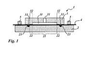
- FIG. 1 illustrated mold 1 is composed of two mold parts 2, 3.
- FIG. 1 shows the mold in the closed position prior to injection of the plastic melt.
- the plastic film 4 to be back-injected is in FIG. 1 arranged clamped between the mold parts 2, 3.
- the plastic film 4 is of multilayer construction in the preferred embodiments shown in the figures and has a carrier film consisting of a thermoplastic film with a layer thickness between 6 ⁇ m and 300 ⁇ m, more preferably between 10 ⁇ m and 50 ⁇ m.
- the formulation of the carrier film is preferably selected such that the glass transition temperature of the carrier film is between 10 and 200 ° C., more preferably between 20 and 150 ° C.
- the carrier film is preferably made of PET, BOPP, PVC, PC, PET-PC, polypropylene (PP), ABS, ABS-PC, polystyrene, PMMA.
- the carrier film may be present as a single-layer material or as a composite material, for example as a laminate of a plurality of individual films, and / or be coated with one or more paint layers.
- the lacquer layers may be, for example, adhesion promoter layers or protective layers or layers for reducing the electrostatic charge of the carrier film.
- the plastic film 4 further layers, which are arranged on the carrier film, in particular a heat-activatable release layer for subsequent removal of the carrier film from the remaining, remaining on the molding layer package of the plastic film 4, a single or multi-layer protective layer, a single or multi-layer decorative layer and a heat-activatable adhesive layer.
- the decorative layer can thereby decorative layers, such. opaque, translucent or transparent lake layers, replicate resist layers, reflective layers or metal layers, and / or functional layers such as e.g. electrical interconnects of metal and / or conductive polymers, electronic components, optoelectronic components or photosensitive components.
- the release layer has in particular a layer thickness of 0.001 to 0.5 microns, the decorative layer in particular a layer thickness of 0.1 to 50 microns and the adhesive layer in particular a layer thickness of 0.01 to 10 microns.
- the decorative layer can have a motif as an endless pattern, the exact location between the motif and molding does not matter.
- the decorative layer may also have a single image as a motif, which is to be applied in a precise position on the molding.
- it is necessary that the plastic film is positioned accordingly accurately on the decorating surface. This is done by means of so-called register marks on the plastic film, which are detected by preferably optical sensors on the mold.
- the optical sensors control a conveyor of the plastic film, which transports the plastic film in the mold, preferably as a continuous web of a roll or as a single sheet.
- the plastic melt used are preferably thermoplastics such as ABS, ABS-PC, polypropylene (PP), polycarbonate (PC), polystyrene, ABS-PC, PMMA, PET, PET-PC or combinations of these materials.
- thermoplastics such as ABS, ABS-PC, polypropylene (PP), polycarbonate (PC), polystyrene, ABS-PC, PMMA, PET, PET-PC or combinations of these materials.
- the mold 2 - the in FIG. 1 lower mold - has a decorating surface 21.
- the mold 3 - the in FIG. 1 Upper mold part - has an inlet channel 31 for the plastic melt. Between the mutually facing surfaces of the two tool parts 2, 3, a cavity 11 is formed. This cavity 11 forms the cavity of the molding tool, ie the space in which the plastic melt injected via the inlet channel 31 is received, in order to form the plastic molding therein with injection of the plastic film 4.
- the plastic film 4 to be back-injected is arranged taut in the closed mold.
- a flat clamping surface 22 and a recessed channel 23 is formed circumferentially around the decorating surface 21 on the lower tool part 2, as shown in the perspective view in FIG. 3 can be seen.
- the clamping surface 22 is formed as a strip-shaped surface which is formed directly adjacent to the decorative surface 21 and surrounds this as a closed annular surface.
- the inner edge of this annular clamping surface 22 coincides directly with the outer edge of the decorating surface 21.
- At the outer edge of the clamping surface 22 of the recess channel 23 is formed. It forms a circumferential recess channel 23, which runs around the entire outer edge of the clamping surface 22.
- the circumferential recess channel 23 thus forms the outer edge of the clamping surface 22.
- a plane clamping surface 32 running around in the manner of a closed ring is likewise formed in the surface facing the lower tool part 2. It is as clamping surface 32 congruent with the clamping surface 22 of the lower tool part 2, that is, it is designed in their dimensions and in their arrangement so that when the tool is closed, the clamping surface 32 is arranged flush with the clamping surface 22, wherein the back-foiling plastic film 4th interposed, that is, lying between clamping surface 22 and clamping surface 32 is arranged.
- the clamping surfaces 22 and 32 lie flat on the bottom or the top of the plastic film 4. This is best in the sectional view in FIG. 1 to recognize.
- an engagement strip 33 is arranged, which engages complementarily in the formed in the lower tool part 2 recess channel 23.
- engageable engagement strip 33 is formed as a circumferential projecting strip which surrounds the annular clamping surface 32 in the same manner in the manner of a closed ring, as the recessed channel 23 surrounds the annular clamping surface 22 and the decorating surface 22 arranged therein in the lower tool part 2. Due to the congruent arrangement results in the closed position of the tool in FIG. 1 shown engagement of the engagement strip 33 in the recess channel 23, wherein the intermediate plastic film 4 is guided by the engagement strip 33 in the recess channel 23, that is pulled in by the action of the engagement strip 33.
- the plastic film 4 of recess channel 23 and engaging strip 33 is acted upon within predetermined surface areas, in particular predetermined clamping zones.
- the plastic film 4 may have different properties in these clamping zones than on the remaining surface.
- apertures in the plastic film 4 may be provided in the clamping zones, engage in the recessed channel 23 and engagement strip 33 or the plastic film 4 has a different layer structure in the clamping zones, either individual layers are removed, for example, the adhesive layer or further layers are additionally provided For example, adhesive layers or release layers or other functional layers that improve the mechanical properties of the plastic film 4 for clamping.
- the fixing frame 5 is in the perspective FIGS. 2 and 3 omitted. It is preferably designed as a peripheral fixing frame 5, which is arranged at a distance from the outer edge of the circumferential recess channel 23. It ensures that the plastic film 4 rests flat on the clamping surface 22 of the lower tool part 2 before closing the tool and is fixed in this position on the tool part 2. If the tool 1 is then closed and the in FIG. 1 is set, the circumferential engagement strip 33 of the upper tool part 3 comes into engagement with the circumferential recess channel 23 in the lower tool part 2.
- the on the lower tool part 2 on the clamping surface 22 flat and fixed over the fixing plastic film 4 is in the range between Engagement strip 33 and recess channel 23 pulled in, so that the plastic film 4 is stretched over the circumferential clamping surface 22 and finally clamped in the closed position of the tool between the lower clamping surface 22 and the upper clamping surface 32 wrinkle-free, surface clamped.
- the arranged between the clamping surfaces 22, 32 plastic film 4 forms a seal of the mold 1 in the closed position.
- the cavity 11 is formed by the cavity formed between the two mold parts 2, 3 with the mold 1 closed.
- the upper mold part 3 a recess which is bounded by the inner edge of the upper clamping surface 32.
- This recess is how out of the FIGS. 2 and 3 recognizable, formed substantially cuboid. It has rounded corners in the lateral edges.
- the lower boundary of the cavity 11 is formed by the lower mold part 2. In FIG. 1 this is the lower boundary of the cavity 11 to the decorating surface 21, which is bounded by the inner edge of the lower clamping surface 22 and in the case of FIG. 1 in the same plane as the clamping surface 22 is arranged in alignment.
- the on the lower mold part 2 resting on the decorating surface 21 between the mold parts 2 and 3 interposed plastic film 4 is back-injected with the introduced via the inlet channel 31 during the injection molding process plastic melt.
- the plastic film may be a hot stamping foil or else another plastic foil with or without carrier foil.
- the tool is opened and removed from the decorated with the plastic film 4 plastic molding.
- a transfer foil such as e.g. a hot stamping foil from a carrier foil and a transfer layer or another foil with carrier foil detachably arranged thereon
- the carrier foil is removed from the transfer layer adhering to the plastic blank when the plastic preform is removed.
- FIG. 4 shows a second embodiment of a mold 1, which is a modification of the first in the FIGS. 1 to 3 illustrated embodiment is.
- the difference between these exemplary embodiments lies only in the design of the cavity 11 FIG. 4
- the recess formed in the upper tool part 3 has a concave upper inner wall which, however, like FIG. 4 shows, with the plane of the clamping surface 32 as well as in the embodiment in FIG. 1 forms a right-angled edge, since the concave upper inner wall so at right angles expires in the flat bottom.
- FIG. 5 shows a third embodiment of a mold 1 not according to the invention, which is also modified only by the design of the cavity 11 with respect to the first embodiment and also with respect to the second embodiment. The difference from the first embodiment is in FIG.
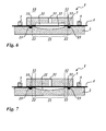
- FIG. 6 shows a fourth embodiment not according to the invention, which is also modified from the previous embodiments only in the embodiment of the cavity 11.
- the tensioned when the mold is closed plastic film 4, such as FIG. 6 shows, not resting on the decorating surface 21, but only on the clamping surface 22 with its underside resting and stretched at a distance above the decorating surface 21.
- plastic film 4 is in the same manner as in the embodiments in the FIGS.
- the upper clamping surface 32 of the upper mold 3 flat overlying to form a sealing region which seals the cavity between the mold parts 2, 3. If during the injection process the plastic melt in FIG. 6 is introduced via the inlet channel 31, the plastic film 4 is softened by the plastic melt on the one hand by the high temperature of the plastic melt and on the other hand moved to the decorating surface 21 until the plastic film 4 comes to the flat contact on the decorating surface 21 and further stretched.
- FIG. 7 shows a fifth modified embodiment not according to the invention. This is a modification of the in FIG. 6 illustrated embodiment.
- the difference over FIG. 6 consists in that no recess is formed in the upper mold part 3, but the upper boundary wall of the cavity is formed by the flat bottom of the upper mold 3, said flat bottom in the plane of the upper clamping surface 32 is arranged in alignment. If, during the injection process, the plastic melt via the inlet channel 31 into the mold in FIG. 7 is admitted, the plastic melt urges the softened by the high temperature of the plastic melt plastic film 4 in a similar manner as in the embodiment in FIG. 6 on the decorating surface 21 of the lower tool part 2, until a flat support of the plastic film is obtained on the concave decorative surface.
- Embodiments of the present invention enable the provision, preferably flatter, of plastic parts, i.
- IM-decorated plastic parts which preferably have no rounding or radius at their edges delimiting the decorating area 21.
- these plastic parts have no, preferably visible, seam or "parting line”.
- wrinkle-free decorated plastic parts can be produced.
- the wrinkle-free was achieved by the edge or the edge of Dekorier perennial Kunststoff ceremoniess had a small or very small edge radius, which is eliminated with the present invention.
- This edge radius caused the plastic melt or injection molding compound, even when flowing into the mold, to smoothly pull the plastic film and push out possible wrinkles.
- the plastic melt or injection molding material acted practically like a squeegee or a wedge and the edge radius caused a Drawing of the plastic film within the mold.
- the stretching is necessary because the plastic film is heated during the injection molding or inflow of the hot plastic melt or injection molding compound, ie softens and thereby expands, so that wrinkles can occur.
- the plastic film is drawn in the formation of the plastic part in the edge radius and / or extends into the edge radius.
- embodiments of the invention however, it is no longer necessary to provide an edge radius which causes a "funnel-like focusing" of the plastic film 4. Therefore, the present invention makes the edge shapes of the molded plastic parts more versatile. Thus, embodiments of the invention can provide plastic parts that can be decorated more precisely than previously possible.
- Embodiments of the invention provide particularly advantageous to durably tighten the plastic film 4 before and during injection molding so that the plastic film 4 in the decorating area 21 is wrinkle-free.
- a plastic receiving space which is formed between the top of the first mold part 2 and the bottom of the second mold part 3 in Dekorierpsych Scheme 21, in the region defined by the clamping surface portion 22 plane, ie in the Dekorierpsych Scheme, only slightly convex or concave curved or even.
- Embodiments of the invention advantageously provide that the plastic film 4 is held or clamped under tension by means of the engagement arrangement 33 and the recessed area 23.
- tensioning the plastic film 4 by means of the engagement arrangement 33 and the recess area 23 the plastic film 4 can be greatly deformed.
- the clamping surface region 22 prevents wrinkling of the plastic film 4 in the decorative surface region 21.
- the engagement arrangement 33 and the recess area 23 can act as tension elements, because the engagement arrangement and the recess area "take along" the plastic film when closing the molding tool.
- the tension of the plastic film 4 can be increased when closing the mold 1.
- the plastic film 4 can be pulled smooth when closing the mold.
- the engagement arrangement 33 and the recess area 23 in such a way that the tension of the plastic film 4 is independent of the contour shape of the decorating area 21 and / or of the plastic receiving space 11.
- the tension of the plastic film 4 preferably takes place from the center of the decoration surface area 21 and / or the plastic receiving space 11.
- the plastic film 4 can be tensioned on all sides uniformly over the entire decoration surface area 21 without wrinkles.
- the clamping surface area 22 is adapted to the contour of the Dekorier vom Schemes 21.
Landscapes
- Engineering & Computer Science (AREA)
- Manufacturing & Machinery (AREA)
- Mechanical Engineering (AREA)
- Injection Moulding Of Plastics Or The Like (AREA)
- Moulds For Moulding Plastics Or The Like (AREA)
Applications Claiming Priority (2)
| Application Number | Priority Date | Filing Date | Title |
|---|---|---|---|
| DE102011010971A DE102011010971A1 (de) | 2011-02-10 | 2011-02-10 | Formwerkzeug zum Hinterspritzen einer Kunststofffolie mit einer Kunststoffschmelze |
| PCT/EP2012/000569 WO2012107222A1 (de) | 2011-02-10 | 2012-02-08 | Formwerkzeug zum hinterspritzen einer kunststofffolie mit einer kunststoffschmelze |
Publications (2)
| Publication Number | Publication Date |
|---|---|
| EP2673126A1 EP2673126A1 (de) | 2013-12-18 |
| EP2673126B1 true EP2673126B1 (de) | 2015-04-15 |
Family
ID=45592322
Family Applications (1)
| Application Number | Title | Priority Date | Filing Date |
|---|---|---|---|
| EP12703706.7A Active EP2673126B1 (de) | 2011-02-10 | 2012-02-08 | Formwerkzeug zum hinterspritzen einer kunststofffolie mit einer kunststoffschmelze |
Country Status (7)
| Country | Link |
|---|---|
| US (1) | US9505154B2 (enExample) |
| EP (1) | EP2673126B1 (enExample) |
| JP (1) | JP2014504973A (enExample) |
| KR (1) | KR20140034746A (enExample) |
| CN (1) | CN103354777B (enExample) |
| DE (1) | DE102011010971A1 (enExample) |
| WO (1) | WO2012107222A1 (enExample) |
Families Citing this family (4)
| Publication number | Priority date | Publication date | Assignee | Title |
|---|---|---|---|---|
| JP6346474B2 (ja) * | 2014-03-17 | 2018-06-20 | アピックヤマダ株式会社 | 樹脂モールド方法および樹脂モールド金型 |
| EP3085520B1 (de) * | 2015-04-22 | 2017-07-19 | PMA/Tools AG | Verfahren und vorrichtung zur herstellung eines optischen koppelelements aus elastomer |
| DE102017010019A1 (de) * | 2016-11-02 | 2018-05-03 | Mann + Hummel Gmbh | Einheit zum Regeln oder Steuern eines Fluiddrucks |
| DE102018212670A1 (de) * | 2018-07-30 | 2020-01-30 | Robert Bosch Gmbh | Bauteil mit zwei verkapselnd zusammenwirkenden Kunststoffverkapselungselementen |
Family Cites Families (22)
| Publication number | Priority date | Publication date | Assignee | Title |
|---|---|---|---|---|
| JPH0618695B2 (ja) * | 1988-08-24 | 1994-03-16 | 日本写真印刷株式会社 | インモールド成形用金型 |
| JPH02158315A (ja) * | 1988-12-12 | 1990-06-18 | Nissha Printing Co Ltd | 射出成形同時絵付け装置用金型 |
| JPH0454185A (ja) | 1990-06-20 | 1992-02-21 | Mitsui Petrochem Ind Ltd | ナフタロシアニン化合物およびその製造方法 |
| JPH04339613A (ja) * | 1991-05-16 | 1992-11-26 | Dainippon Printing Co Ltd | インモールド射出同時絵付装置および方法 |
| JP3558135B2 (ja) * | 1991-10-14 | 2004-08-25 | 大日本印刷株式会社 | インモールド射出成形同時絵付用金型 |
| WO1996009155A1 (en) * | 1994-09-23 | 1996-03-28 | The Geon Company | Method and device for injection molding |
| JPH09254185A (ja) * | 1996-03-22 | 1997-09-30 | Marui Kogyo Kk | 転写形成装置 |
| JPH115230A (ja) * | 1997-06-17 | 1999-01-12 | Dainippon Printing Co Ltd | 射出成形同時絵付装置 |
| DE19733800A1 (de) * | 1997-08-05 | 1999-02-11 | Sachsenring Automobiltechnik | Verfahren zur Herstellung eines Abstellteils mit einem Antirutschbelag |
| US6818305B2 (en) * | 1998-05-22 | 2004-11-16 | Patent Holding Company | Molding method and metal-covered component formed thereby |
| US6214157B1 (en) * | 1998-10-21 | 2001-04-10 | R + S Technik | Vehicle trim component having two-part cover material, and method and apparatus for producing the same |
| JP4371493B2 (ja) * | 1999-09-30 | 2009-11-25 | 日本写真印刷株式会社 | 絵柄付成形品製造方法 |
| JP4161752B2 (ja) * | 2003-03-13 | 2008-10-08 | トヨタ紡織株式会社 | 表皮を有する成形品の成形方法および成形装置 |
| TWI326243B (en) | 2003-03-25 | 2010-06-21 | Nissha Printing | A method for production of an in-mold decorated product in injection molding and a mold for in-mold decorating in injection molding |
| EP2045062A3 (en) * | 2003-03-31 | 2009-09-16 | Nissha Printing Co., Ltd. | Mold for in-mold decoration |
| JP4429061B2 (ja) * | 2003-03-31 | 2010-03-10 | 日本写真印刷株式会社 | 成形同時絵付け用金型 |
| JP2005088315A (ja) * | 2003-09-17 | 2005-04-07 | Nissha Printing Co Ltd | 射出成形同時加飾用金型および射出成形同時加飾品の製造方法 |
| JP2005333277A (ja) * | 2004-05-18 | 2005-12-02 | Pioneer Electronic Corp | スピーカ用センターキャップの製造方法 |
| CA2598551A1 (en) * | 2005-02-22 | 2006-08-31 | Dow Global Technologies Inc. | Molded parts with mixed material surface areas and processes for their production |
| US20060220274A1 (en) * | 2005-04-01 | 2006-10-05 | David Dooley | Apparatus and method for making an automotive door trim panel with a wrapped turn down flange |
| JP2007283704A (ja) * | 2006-04-19 | 2007-11-01 | Toyoda Gosei Co Ltd | 樹脂成形体及びその製造方法 |
| CN101450520B (zh) * | 2007-11-29 | 2012-03-14 | 康准电子科技(昆山)有限公司 | 模内装饰的成型装置 |
-
2011
- 2011-02-10 DE DE102011010971A patent/DE102011010971A1/de not_active Withdrawn
-
2012
- 2012-02-08 WO PCT/EP2012/000569 patent/WO2012107222A1/de not_active Ceased
- 2012-02-08 CN CN201280008276.3A patent/CN103354777B/zh active Active
- 2012-02-08 KR KR1020137020454A patent/KR20140034746A/ko not_active Ceased
- 2012-02-08 JP JP2013552882A patent/JP2014504973A/ja active Pending
- 2012-02-08 US US13/983,188 patent/US9505154B2/en not_active Expired - Fee Related
- 2012-02-08 EP EP12703706.7A patent/EP2673126B1/de active Active
Also Published As
| Publication number | Publication date |
|---|---|
| KR20140034746A (ko) | 2014-03-20 |
| JP2014504973A (ja) | 2014-02-27 |
| US20130307186A1 (en) | 2013-11-21 |
| EP2673126A1 (de) | 2013-12-18 |
| US9505154B2 (en) | 2016-11-29 |
| WO2012107222A1 (de) | 2012-08-16 |
| DE102011010971A8 (de) | 2012-10-04 |
| CN103354777A (zh) | 2013-10-16 |
| DE102011010971A1 (de) | 2012-08-16 |
| CN103354777B (zh) | 2016-01-20 |
Similar Documents
| Publication | Publication Date | Title |
|---|---|---|
| DE102011102722B4 (de) | Verfahren zum In-Mold-Dekorieren | |
| DE69706941T2 (de) | Verfahren und Vorrichtung zum Spritzgiessen mit Verzierfolie | |
| DE69623104T2 (de) | Foliendekorierende Spritzgussmaschine und foliendekorierendes Spritzgussverfahren | |
| DE69609296T2 (de) | Kunststoffspritzgiessmaschine zum Aufbringen einer Dekorfolie | |
| EP0495219A2 (de) | Verfahren und Vorrichtung zum Herstellen laminierter Formteile | |
| EP2556940B1 (de) | Verfahren zum Herstellen eines Formteils | |
| WO2012163677A1 (de) | Fertigungseinrichtung und verfahren zur herstellung in-mould-dekorierter kunststoffformteile | |
| EP2673126B1 (de) | Formwerkzeug zum hinterspritzen einer kunststofffolie mit einer kunststoffschmelze | |
| DE102018128194A1 (de) | Verfahren zur Herstellung eines Bauteils sowie Spritzgießvorrichtung | |
| DE102009021413B4 (de) | Vorrichtung und Verfahren zur Herstellung eines eine Dekoroberfläche aufweisenden Bauteils | |
| EP3880425B1 (de) | Verfahren zur herstellung eines bauteils sowie spritzgiessvorrichtung | |
| DE69415247T2 (de) | Verfahren zur Herstellung eines Formkörpers mit versiegelten Dekorationen | |
| EP4384367A1 (de) | Spritzgussfertigung eines bauteils | |
| DE10221482C1 (de) | Vorrichtung zum Herstellen eines abgewinkelt profilierten Formteiles, das mit einer Prägefolie dekoriert wird | |
| EP3127679B1 (de) | Vorrichtung und verfahren zur herstellung eines kunststoff-spritzgussteils mit dekoreinlage | |
| WO2010051866A1 (de) | Verfahren und vorrichtung zur herstellung eines formteils mit dekoroberfläche | |
| EP2236263A2 (de) | Spritzgießwerkzeug und Spritzgießverfahren zur Herstellung mehrteiliger Formteile | |
| EP2326479B1 (de) | Verfahren und vorrichtung zur herstellung eines formteils mit mehreren aneinander grenzenden, unterschiedlichen dekorbereichen | |
| LU500899B1 (de) | Verfahren zur Herstellung eines Kombinationsbauteils und Kombinationsbauteil | |
| DE102011006034A1 (de) | Verfahren zur Herstellung eines Verbundbauteils | |
| DE102007030307B4 (de) | Verfahren zum Herstellen von farbigen, dreidimensional strukturierten Bauteilen mit Freiformflächen | |
| DE102007029716A1 (de) | Kunststoffaufbauteil für ein Fahrzeug und Verfahren zu dessen Herstellung | |
| EP3946879B1 (de) | Verfahren zum hinterspritzen von kaltverformten glaskomponenten mit kunststoff | |
| EP2815865B1 (de) | Verfahren zur Herstellung eines Kunststoff-Bauteilverbundes | |
| WO2004103678A1 (de) | Verfahren zur herstellung eines formteils durch hinterspritzen eines flächigen dekormaterials sowie mit einem eingebetteten dekormaterial |
Legal Events
| Date | Code | Title | Description |
|---|---|---|---|
| PUAI | Public reference made under article 153(3) epc to a published international application that has entered the european phase |
Free format text: ORIGINAL CODE: 0009012 |
|
| 17P | Request for examination filed |
Effective date: 20130827 |
|
| AK | Designated contracting states |
Kind code of ref document: A1 Designated state(s): AL AT BE BG CH CY CZ DE DK EE ES FI FR GB GR HR HU IE IS IT LI LT LU LV MC MK MT NL NO PL PT RO RS SE SI SK SM TR |
|
| DAX | Request for extension of the european patent (deleted) | ||
| GRAP | Despatch of communication of intention to grant a patent |
Free format text: ORIGINAL CODE: EPIDOSNIGR1 |
|
| INTG | Intention to grant announced |
Effective date: 20140924 |
|
| GRAS | Grant fee paid |
Free format text: ORIGINAL CODE: EPIDOSNIGR3 |
|
| GRAP | Despatch of communication of intention to grant a patent |
Free format text: ORIGINAL CODE: EPIDOSNIGR1 |
|
| GRAA | (expected) grant |
Free format text: ORIGINAL CODE: 0009210 |
|
| INTG | Intention to grant announced |
Effective date: 20150224 |
|
| AK | Designated contracting states |
Kind code of ref document: B1 Designated state(s): AL AT BE BG CH CY CZ DE DK EE ES FI FR GB GR HR HU IE IS IT LI LT LU LV MC MK MT NL NO PL PT RO RS SE SI SK SM TR |
|
| REG | Reference to a national code |
Ref country code: GB Ref legal event code: FG4D Free format text: NOT ENGLISH Ref country code: CH Ref legal event code: EP |
|
| REG | Reference to a national code |
Ref country code: IE Ref legal event code: FG4D Free format text: LANGUAGE OF EP DOCUMENT: GERMAN |
|
| REG | Reference to a national code |
Ref country code: AT Ref legal event code: REF Ref document number: 721690 Country of ref document: AT Kind code of ref document: T Effective date: 20150515 |
|
| REG | Reference to a national code |
Ref country code: DE Ref legal event code: R096 Ref document number: 502012002860 Country of ref document: DE Effective date: 20150528 |
|
| REG | Reference to a national code |
Ref country code: NL Ref legal event code: VDEP Effective date: 20150415 |
|
| REG | Reference to a national code |
Ref country code: LT Ref legal event code: MG4D |
|
| PG25 | Lapsed in a contracting state [announced via postgrant information from national office to epo] |
Ref country code: NL Free format text: LAPSE BECAUSE OF FAILURE TO SUBMIT A TRANSLATION OF THE DESCRIPTION OR TO PAY THE FEE WITHIN THE PRESCRIBED TIME-LIMIT Effective date: 20150415 |
|
| PG25 | Lapsed in a contracting state [announced via postgrant information from national office to epo] |
Ref country code: PT Free format text: LAPSE BECAUSE OF FAILURE TO SUBMIT A TRANSLATION OF THE DESCRIPTION OR TO PAY THE FEE WITHIN THE PRESCRIBED TIME-LIMIT Effective date: 20150817 Ref country code: ES Free format text: LAPSE BECAUSE OF FAILURE TO SUBMIT A TRANSLATION OF THE DESCRIPTION OR TO PAY THE FEE WITHIN THE PRESCRIBED TIME-LIMIT Effective date: 20150415 Ref country code: NO Free format text: LAPSE BECAUSE OF FAILURE TO SUBMIT A TRANSLATION OF THE DESCRIPTION OR TO PAY THE FEE WITHIN THE PRESCRIBED TIME-LIMIT Effective date: 20150715 Ref country code: HR Free format text: LAPSE BECAUSE OF FAILURE TO SUBMIT A TRANSLATION OF THE DESCRIPTION OR TO PAY THE FEE WITHIN THE PRESCRIBED TIME-LIMIT Effective date: 20150415 Ref country code: FI Free format text: LAPSE BECAUSE OF FAILURE TO SUBMIT A TRANSLATION OF THE DESCRIPTION OR TO PAY THE FEE WITHIN THE PRESCRIBED TIME-LIMIT Effective date: 20150415 Ref country code: LT Free format text: LAPSE BECAUSE OF FAILURE TO SUBMIT A TRANSLATION OF THE DESCRIPTION OR TO PAY THE FEE WITHIN THE PRESCRIBED TIME-LIMIT Effective date: 20150415 |
|
| PG25 | Lapsed in a contracting state [announced via postgrant information from national office to epo] |
Ref country code: LV Free format text: LAPSE BECAUSE OF FAILURE TO SUBMIT A TRANSLATION OF THE DESCRIPTION OR TO PAY THE FEE WITHIN THE PRESCRIBED TIME-LIMIT Effective date: 20150415 Ref country code: IS Free format text: LAPSE BECAUSE OF FAILURE TO SUBMIT A TRANSLATION OF THE DESCRIPTION OR TO PAY THE FEE WITHIN THE PRESCRIBED TIME-LIMIT Effective date: 20150815 Ref country code: GR Free format text: LAPSE BECAUSE OF FAILURE TO SUBMIT A TRANSLATION OF THE DESCRIPTION OR TO PAY THE FEE WITHIN THE PRESCRIBED TIME-LIMIT Effective date: 20150716 Ref country code: RS Free format text: LAPSE BECAUSE OF FAILURE TO SUBMIT A TRANSLATION OF THE DESCRIPTION OR TO PAY THE FEE WITHIN THE PRESCRIBED TIME-LIMIT Effective date: 20150415 |
|
| REG | Reference to a national code |
Ref country code: DE Ref legal event code: R097 Ref document number: 502012002860 Country of ref document: DE |
|
| PG25 | Lapsed in a contracting state [announced via postgrant information from national office to epo] |
Ref country code: EE Free format text: LAPSE BECAUSE OF FAILURE TO SUBMIT A TRANSLATION OF THE DESCRIPTION OR TO PAY THE FEE WITHIN THE PRESCRIBED TIME-LIMIT Effective date: 20150415 Ref country code: DK Free format text: LAPSE BECAUSE OF FAILURE TO SUBMIT A TRANSLATION OF THE DESCRIPTION OR TO PAY THE FEE WITHIN THE PRESCRIBED TIME-LIMIT Effective date: 20150415 |
|
| PLBE | No opposition filed within time limit |
Free format text: ORIGINAL CODE: 0009261 |
|
| STAA | Information on the status of an ep patent application or granted ep patent |
Free format text: STATUS: NO OPPOSITION FILED WITHIN TIME LIMIT |
|
| PG25 | Lapsed in a contracting state [announced via postgrant information from national office to epo] |
Ref country code: PL Free format text: LAPSE BECAUSE OF FAILURE TO SUBMIT A TRANSLATION OF THE DESCRIPTION OR TO PAY THE FEE WITHIN THE PRESCRIBED TIME-LIMIT Effective date: 20150415 Ref country code: CZ Free format text: LAPSE BECAUSE OF FAILURE TO SUBMIT A TRANSLATION OF THE DESCRIPTION OR TO PAY THE FEE WITHIN THE PRESCRIBED TIME-LIMIT Effective date: 20150415 Ref country code: RO Free format text: LAPSE BECAUSE OF NON-PAYMENT OF DUE FEES Effective date: 20150415 Ref country code: SK Free format text: LAPSE BECAUSE OF FAILURE TO SUBMIT A TRANSLATION OF THE DESCRIPTION OR TO PAY THE FEE WITHIN THE PRESCRIBED TIME-LIMIT Effective date: 20150415 |
|
| 26N | No opposition filed |
Effective date: 20160118 |
|
| PG25 | Lapsed in a contracting state [announced via postgrant information from national office to epo] |
Ref country code: IT Free format text: LAPSE BECAUSE OF FAILURE TO SUBMIT A TRANSLATION OF THE DESCRIPTION OR TO PAY THE FEE WITHIN THE PRESCRIBED TIME-LIMIT Effective date: 20150415 |
|
| PG25 | Lapsed in a contracting state [announced via postgrant information from national office to epo] |
Ref country code: SI Free format text: LAPSE BECAUSE OF FAILURE TO SUBMIT A TRANSLATION OF THE DESCRIPTION OR TO PAY THE FEE WITHIN THE PRESCRIBED TIME-LIMIT Effective date: 20150415 Ref country code: BE Free format text: LAPSE BECAUSE OF NON-PAYMENT OF DUE FEES Effective date: 20160229 |
|
| PG25 | Lapsed in a contracting state [announced via postgrant information from national office to epo] |
Ref country code: MC Free format text: LAPSE BECAUSE OF FAILURE TO SUBMIT A TRANSLATION OF THE DESCRIPTION OR TO PAY THE FEE WITHIN THE PRESCRIBED TIME-LIMIT Effective date: 20150415 Ref country code: LU Free format text: LAPSE BECAUSE OF FAILURE TO SUBMIT A TRANSLATION OF THE DESCRIPTION OR TO PAY THE FEE WITHIN THE PRESCRIBED TIME-LIMIT Effective date: 20160208 |
|
| REG | Reference to a national code |
Ref country code: CH Ref legal event code: PL |
|
| GBPC | Gb: european patent ceased through non-payment of renewal fee |
Effective date: 20160208 |
|
| PG25 | Lapsed in a contracting state [announced via postgrant information from national office to epo] |
Ref country code: LI Free format text: LAPSE BECAUSE OF NON-PAYMENT OF DUE FEES Effective date: 20160229 Ref country code: CH Free format text: LAPSE BECAUSE OF NON-PAYMENT OF DUE FEES Effective date: 20160229 |
|
| REG | Reference to a national code |
Ref country code: FR Ref legal event code: ST Effective date: 20161028 |
|
| REG | Reference to a national code |
Ref country code: IE Ref legal event code: MM4A |
|
| PG25 | Lapsed in a contracting state [announced via postgrant information from national office to epo] |
Ref country code: IE Free format text: LAPSE BECAUSE OF NON-PAYMENT OF DUE FEES Effective date: 20160208 Ref country code: GB Free format text: LAPSE BECAUSE OF NON-PAYMENT OF DUE FEES Effective date: 20160208 Ref country code: FR Free format text: LAPSE BECAUSE OF NON-PAYMENT OF DUE FEES Effective date: 20160229 |
|
| PG25 | Lapsed in a contracting state [announced via postgrant information from national office to epo] |
Ref country code: SE Free format text: LAPSE BECAUSE OF FAILURE TO SUBMIT A TRANSLATION OF THE DESCRIPTION OR TO PAY THE FEE WITHIN THE PRESCRIBED TIME-LIMIT Effective date: 20150415 |
|
| PG25 | Lapsed in a contracting state [announced via postgrant information from national office to epo] |
Ref country code: MT Free format text: LAPSE BECAUSE OF FAILURE TO SUBMIT A TRANSLATION OF THE DESCRIPTION OR TO PAY THE FEE WITHIN THE PRESCRIBED TIME-LIMIT Effective date: 20150415 |
|
| REG | Reference to a national code |
Ref country code: AT Ref legal event code: MM01 Ref document number: 721690 Country of ref document: AT Kind code of ref document: T Effective date: 20170208 |
|
| PG25 | Lapsed in a contracting state [announced via postgrant information from national office to epo] |
Ref country code: SM Free format text: LAPSE BECAUSE OF FAILURE TO SUBMIT A TRANSLATION OF THE DESCRIPTION OR TO PAY THE FEE WITHIN THE PRESCRIBED TIME-LIMIT Effective date: 20150415 Ref country code: HU Free format text: LAPSE BECAUSE OF FAILURE TO SUBMIT A TRANSLATION OF THE DESCRIPTION OR TO PAY THE FEE WITHIN THE PRESCRIBED TIME-LIMIT; INVALID AB INITIO Effective date: 20120208 Ref country code: AT Free format text: LAPSE BECAUSE OF NON-PAYMENT OF DUE FEES Effective date: 20170208 Ref country code: CY Free format text: LAPSE BECAUSE OF FAILURE TO SUBMIT A TRANSLATION OF THE DESCRIPTION OR TO PAY THE FEE WITHIN THE PRESCRIBED TIME-LIMIT Effective date: 20150415 |
|
| PG25 | Lapsed in a contracting state [announced via postgrant information from national office to epo] |
Ref country code: TR Free format text: LAPSE BECAUSE OF FAILURE TO SUBMIT A TRANSLATION OF THE DESCRIPTION OR TO PAY THE FEE WITHIN THE PRESCRIBED TIME-LIMIT Effective date: 20150415 Ref country code: MK Free format text: LAPSE BECAUSE OF FAILURE TO SUBMIT A TRANSLATION OF THE DESCRIPTION OR TO PAY THE FEE WITHIN THE PRESCRIBED TIME-LIMIT Effective date: 20150415 |
|
| PG25 | Lapsed in a contracting state [announced via postgrant information from national office to epo] |
Ref country code: BG Free format text: LAPSE BECAUSE OF FAILURE TO SUBMIT A TRANSLATION OF THE DESCRIPTION OR TO PAY THE FEE WITHIN THE PRESCRIBED TIME-LIMIT Effective date: 20150415 |
|
| PG25 | Lapsed in a contracting state [announced via postgrant information from national office to epo] |
Ref country code: AL Free format text: LAPSE BECAUSE OF FAILURE TO SUBMIT A TRANSLATION OF THE DESCRIPTION OR TO PAY THE FEE WITHIN THE PRESCRIBED TIME-LIMIT Effective date: 20150415 |
|
| PGFP | Annual fee paid to national office [announced via postgrant information from national office to epo] |
Ref country code: DE Payment date: 20250224 Year of fee payment: 14 |