EP3085520B1 - Verfahren und vorrichtung zur herstellung eines optischen koppelelements aus elastomer - Google Patents
Verfahren und vorrichtung zur herstellung eines optischen koppelelements aus elastomer Download PDFInfo
- Publication number
- EP3085520B1 EP3085520B1 EP15164586.8A EP15164586A EP3085520B1 EP 3085520 B1 EP3085520 B1 EP 3085520B1 EP 15164586 A EP15164586 A EP 15164586A EP 3085520 B1 EP3085520 B1 EP 3085520B1
- Authority
- EP
- European Patent Office
- Prior art keywords
- coupling element
- mold
- stamping
- punching
- elastomer
- Prior art date
- Legal status (The legal status is an assumption and is not a legal conclusion. Google has not performed a legal analysis and makes no representation as to the accuracy of the status listed.)
- Active
Links
- 230000008878 coupling Effects 0.000 title claims description 109
- 238000010168 coupling process Methods 0.000 title claims description 109
- 238000005859 coupling reaction Methods 0.000 title claims description 109
- 238000000034 method Methods 0.000 title claims description 24
- 229920001971 elastomer Polymers 0.000 title claims description 20
- 239000000806 elastomer Substances 0.000 title claims description 20
- 230000003287 optical effect Effects 0.000 title claims description 15
- 239000000463 material Substances 0.000 claims description 22
- 230000001681 protective effect Effects 0.000 claims description 22
- 238000005520 cutting process Methods 0.000 claims description 12
- 238000004519 manufacturing process Methods 0.000 claims description 10
- 238000009472 formulation Methods 0.000 claims description 9
- 239000000203 mixture Substances 0.000 claims description 9
- 239000000470 constituent Substances 0.000 claims description 6
- 239000004033 plastic Substances 0.000 claims description 4
- 229920003023 plastic Polymers 0.000 claims description 4
- 238000004080 punching Methods 0.000 description 61
- 230000009969 flowable effect Effects 0.000 description 9
- 230000008569 process Effects 0.000 description 9
- 229920001296 polysiloxane Polymers 0.000 description 7
- 230000008901 benefit Effects 0.000 description 5
- 238000001746 injection moulding Methods 0.000 description 5
- -1 polyethylene terephthalate Polymers 0.000 description 4
- XLYOFNOQVPJJNP-UHFFFAOYSA-N water Substances O XLYOFNOQVPJJNP-UHFFFAOYSA-N 0.000 description 3
- 208000031872 Body Remains Diseases 0.000 description 2
- 239000004698 Polyethylene Substances 0.000 description 2
- 239000004743 Polypropylene Substances 0.000 description 2
- 230000005540 biological transmission Effects 0.000 description 2
- 230000008859 change Effects 0.000 description 2
- 238000011065 in-situ storage Methods 0.000 description 2
- 239000004615 ingredient Substances 0.000 description 2
- 229920003229 poly(methyl methacrylate) Polymers 0.000 description 2
- 229920001707 polybutylene terephthalate Polymers 0.000 description 2
- 229920000573 polyethylene Polymers 0.000 description 2
- 229920000139 polyethylene terephthalate Polymers 0.000 description 2
- 239000005020 polyethylene terephthalate Substances 0.000 description 2
- 239000004926 polymethyl methacrylate Substances 0.000 description 2
- 229920001155 polypropylene Polymers 0.000 description 2
- 229920002379 silicone rubber Polymers 0.000 description 2
- 239000004793 Polystyrene Substances 0.000 description 1
- 229920004482 WACKER® Polymers 0.000 description 1
- 239000004676 acrylonitrile butadiene styrene Substances 0.000 description 1
- 238000011109 contamination Methods 0.000 description 1
- 239000000428 dust Substances 0.000 description 1
- 239000007769 metal material Substances 0.000 description 1
- 230000002093 peripheral effect Effects 0.000 description 1
- 239000004417 polycarbonate Substances 0.000 description 1
- 229920000515 polycarbonate Polymers 0.000 description 1
- 238000009417 prefabrication Methods 0.000 description 1
- 238000002360 preparation method Methods 0.000 description 1
- 238000010107 reaction injection moulding Methods 0.000 description 1
- 230000008439 repair process Effects 0.000 description 1
- 238000000926 separation method Methods 0.000 description 1
- 230000003595 spectral effect Effects 0.000 description 1
- 239000012815 thermoplastic material Substances 0.000 description 1
- 230000007704 transition Effects 0.000 description 1
- 239000002699 waste material Substances 0.000 description 1
Images


Classifications
-
- B—PERFORMING OPERATIONS; TRANSPORTING
- B29—WORKING OF PLASTICS; WORKING OF SUBSTANCES IN A PLASTIC STATE IN GENERAL
- B29C—SHAPING OR JOINING OF PLASTICS; SHAPING OF MATERIAL IN A PLASTIC STATE, NOT OTHERWISE PROVIDED FOR; AFTER-TREATMENT OF THE SHAPED PRODUCTS, e.g. REPAIRING
- B29C39/00—Shaping by casting, i.e. introducing the moulding material into a mould or between confining surfaces without significant moulding pressure; Apparatus therefor
- B29C39/003—Shaping by casting, i.e. introducing the moulding material into a mould or between confining surfaces without significant moulding pressure; Apparatus therefor characterised by the choice of material
- B29C39/006—Monomers or prepolymers
-
- B—PERFORMING OPERATIONS; TRANSPORTING
- B26—HAND CUTTING TOOLS; CUTTING; SEVERING
- B26F—PERFORATING; PUNCHING; CUTTING-OUT; STAMPING-OUT; SEVERING BY MEANS OTHER THAN CUTTING
- B26F1/00—Perforating; Punching; Cutting-out; Stamping-out; Apparatus therefor
- B26F1/38—Cutting-out; Stamping-out
- B26F1/3846—Cutting-out; Stamping-out cutting out discs or the like
-
- B—PERFORMING OPERATIONS; TRANSPORTING
- B26—HAND CUTTING TOOLS; CUTTING; SEVERING
- B26F—PERFORATING; PUNCHING; CUTTING-OUT; STAMPING-OUT; SEVERING BY MEANS OTHER THAN CUTTING
- B26F3/00—Severing by means other than cutting; Apparatus therefor
- B26F3/004—Severing by means other than cutting; Apparatus therefor by means of a fluid jet
-
- B—PERFORMING OPERATIONS; TRANSPORTING
- B26—HAND CUTTING TOOLS; CUTTING; SEVERING
- B26F—PERFORATING; PUNCHING; CUTTING-OUT; STAMPING-OUT; SEVERING BY MEANS OTHER THAN CUTTING
- B26F3/00—Severing by means other than cutting; Apparatus therefor
- B26F3/06—Severing by using heat
- B26F3/16—Severing by using heat by radiation
-
- B—PERFORMING OPERATIONS; TRANSPORTING
- B29—WORKING OF PLASTICS; WORKING OF SUBSTANCES IN A PLASTIC STATE IN GENERAL
- B29C—SHAPING OR JOINING OF PLASTICS; SHAPING OF MATERIAL IN A PLASTIC STATE, NOT OTHERWISE PROVIDED FOR; AFTER-TREATMENT OF THE SHAPED PRODUCTS, e.g. REPAIRING
- B29C33/00—Moulds or cores; Details thereof or accessories therefor
- B29C33/38—Moulds or cores; Details thereof or accessories therefor characterised by the material or the manufacturing process
- B29C33/40—Plastics, e.g. foam or rubber
-
- B—PERFORMING OPERATIONS; TRANSPORTING
- B29—WORKING OF PLASTICS; WORKING OF SUBSTANCES IN A PLASTIC STATE IN GENERAL
- B29C—SHAPING OR JOINING OF PLASTICS; SHAPING OF MATERIAL IN A PLASTIC STATE, NOT OTHERWISE PROVIDED FOR; AFTER-TREATMENT OF THE SHAPED PRODUCTS, e.g. REPAIRING
- B29C39/00—Shaping by casting, i.e. introducing the moulding material into a mould or between confining surfaces without significant moulding pressure; Apparatus therefor
- B29C39/22—Component parts, details or accessories; Auxiliary operations
- B29C39/26—Moulds or cores
-
- B—PERFORMING OPERATIONS; TRANSPORTING
- B29—WORKING OF PLASTICS; WORKING OF SUBSTANCES IN A PLASTIC STATE IN GENERAL
- B29C—SHAPING OR JOINING OF PLASTICS; SHAPING OF MATERIAL IN A PLASTIC STATE, NOT OTHERWISE PROVIDED FOR; AFTER-TREATMENT OF THE SHAPED PRODUCTS, e.g. REPAIRING
- B29C69/00—Combinations of shaping techniques not provided for in a single one of main groups B29C39/00 - B29C67/00, e.g. associations of moulding and joining techniques; Apparatus therefore
- B29C69/005—Combinations of shaping techniques not provided for in a single one of main groups B29C39/00 - B29C67/00, e.g. associations of moulding and joining techniques; Apparatus therefore cutting-off or cutting-out a part of a strip-like or sheet-like material, transferring that part and fixing it to an article
-
- B—PERFORMING OPERATIONS; TRANSPORTING
- B29—WORKING OF PLASTICS; WORKING OF SUBSTANCES IN A PLASTIC STATE IN GENERAL
- B29C—SHAPING OR JOINING OF PLASTICS; SHAPING OF MATERIAL IN A PLASTIC STATE, NOT OTHERWISE PROVIDED FOR; AFTER-TREATMENT OF THE SHAPED PRODUCTS, e.g. REPAIRING
- B29C2791/00—Shaping characteristics in general
- B29C2791/004—Shaping under special conditions
- B29C2791/009—Using laser
-
- B—PERFORMING OPERATIONS; TRANSPORTING
- B29—WORKING OF PLASTICS; WORKING OF SUBSTANCES IN A PLASTIC STATE IN GENERAL
- B29C—SHAPING OR JOINING OF PLASTICS; SHAPING OF MATERIAL IN A PLASTIC STATE, NOT OTHERWISE PROVIDED FOR; AFTER-TREATMENT OF THE SHAPED PRODUCTS, e.g. REPAIRING
- B29C2793/00—Shaping techniques involving a cutting or machining operation
- B29C2793/0009—Cutting out
-
- B—PERFORMING OPERATIONS; TRANSPORTING
- B29—WORKING OF PLASTICS; WORKING OF SUBSTANCES IN A PLASTIC STATE IN GENERAL
- B29C—SHAPING OR JOINING OF PLASTICS; SHAPING OF MATERIAL IN A PLASTIC STATE, NOT OTHERWISE PROVIDED FOR; AFTER-TREATMENT OF THE SHAPED PRODUCTS, e.g. REPAIRING
- B29C2793/00—Shaping techniques involving a cutting or machining operation
- B29C2793/0054—Shaping techniques involving a cutting or machining operation partially cutting through the material
-
- B—PERFORMING OPERATIONS; TRANSPORTING
- B29—WORKING OF PLASTICS; WORKING OF SUBSTANCES IN A PLASTIC STATE IN GENERAL
- B29K—INDEXING SCHEME ASSOCIATED WITH SUBCLASSES B29B, B29C OR B29D, RELATING TO MOULDING MATERIALS OR TO MATERIALS FOR MOULDS, REINFORCEMENTS, FILLERS OR PREFORMED PARTS, e.g. INSERTS
- B29K2021/00—Use of unspecified rubbers as moulding material
Definitions
- the invention relates to a method and a device for producing an optical coupling element made of elastomer.
- Optical coupling elements of the aforementioned type are known from EP 2 130 727 A2 and the DE 10 2013 012 849 A1 are known and used to optically couple a arranged in the interior of a vehicle optical sensor with the vehicle window.
- the refractive index of the material used for the coupling element corresponds to the refractive index of the vehicle window.
- the transmission or transmission of the material used for the coupling element for light of the relevant wavelengths is as high as possible. It may, depending on the application to
- silicone materials are used in the prior art as materials for the coupling element.
- examples of such silicone materials are represented by EP 2 181 023 B1 and the EP 2 130 727 A2 also known under the trade names "Silgel 612" and "Semicosil 912".
- Such materials are offered, for example, by Bayer or Wacker.
- the above-mentioned materials are used for "in situ" production of coupling elements, wherein initially flowable and then curing material is introduced into a space in the housing of the optical sensor. The sensor housing is then attached to the disc, so that the cured silicone material then rests against the disc.
- Such a production is complicated both during the initial assembly and in the repair of a vehicle window.
- repairing a vehicle window or a sensor is added as a disadvantage that the non-dimensionally stable coupling element is destroyed and thus is not reusable.
- a prefabrication of coupling elements into a mold is generally from the documents EP 1 413 490 A2 and DE 10 2006 039 065 A1 known. However, detailed information on the preparation are not known from these documents. On this basis, the present invention has for its object to provide a method and an apparatus which allow a simple, inexpensive and flexible production of an optical coupling element.
- a device which comprises: a mold for filling a flowable elastomer formulation or its components for producing a flat body whose thickness is matched to the thickness of a coupling element to be produced, and a removal tool for removing individual coupling elements from the flat body.
- a flat body is first produced whose thickness can be influenced in a simple manner by filling in the mold with a larger or smaller amount of flowable elastomer formulation or its constituents. It is therefore used seen in the thickness direction of a coupling element unilaterally open form, such as a tub.
- the flat body extends over a larger area than is necessary for producing a single coupling element, preferably for producing a plurality of coupling elements. Since a removal of individual coupling elements takes place from the flat body after the elastomer has already hardened and is dimensionally stable, a coupling element separated from the flat body no longer undergoes any shrinkage. Thus, regardless of the recipe used for the coupling element ensures that when removing the coupling element used contour of the dividing line corresponds exactly to the outline of the finished coupling element.
- dimensionally stable it is meant that a coupling element is individually handled, so that the coupling element can be stored and kept ready for mounting to an optical sensor and / or a vehicle window.
- the dimensionally stable coupling element is therefore not produced “in situ” in or on the sensor housing.
- the method according to the invention makes it possible to avoid disadvantages which are associated with an in principle likewise conceivable production of an optical coupling element by injection molding (or reaction injection molding) using a closed injection molding tool.
- injection molding or reaction injection molding
- separate and expensive injection molding tools do not have to be provided for different coupling elements with different dimensions.
- the coupling element according to the invention is made of a silicone elastomer, wherein for the production of the flat body, a flowable silicone formulation or its constituents are introduced into the mold.
- a further, preferred embodiment provides that a bottom portion of the bottom of the mold is separated, wherein the bottom portion forms a detachable from the coupling element protection element for the underside of the coupling element.
- the mold is made of a plastic material which can be cut through more easily than a metal material which is also possible in principle.
- Preferred plastic materials are polystyrene (PS), acrylonitrile-butadiene-styrene (ABS), polycarbonate (PC), polymethyl methacrylate (PMMA), polyethylene terephthalate (PET), polybutylene terephthalate (PBT), polyethylene (PE), polypropylene (PP), silicone or the like ,
- PS polystyrene
- ABS acrylonitrile-butadiene-styrene
- PC polycarbonate
- PMMA polymethyl methacrylate
- PET polyethylene terephthalate
- PBT polybutylene terephthalate
- PE polyethylene
- PP polypropylene
- silicone silicone or the like
- a plastic material also has the advantage of being particularly inexpensive, wherein the material used for a single mold, depending on the size of the mold for several coupling elements.
- a compulsory waste can be
- the bottom portion adheres to the coupling element and can be removed immediately prior to its mounting on a vehicle window. In this way, at least the underside of the coupling element is protected against contamination and / or mechanical influences. In addition, the bottom portion forms a stable support for the coupling element.
- the bottom portion and the coupling element have identical large areas. This has the advantage that the removal process for removing a coupling element from the flat body and for removing a bottom portion of the bottom of the mold is particularly simple.
- a preferred variant of the invention provides, however, that the bottom portion of the coupling element with at least surmounted in terms of area by a handling section. This has the advantage that the bottom section can be gripped on the handling section and the protective element can be removed from the coupling element in a simple manner, without this resulting in contact contact with an optically effective surface of the coupling element.
- preferred ways of removing the coupling element and / or the bottom portion are punching, water or laser beam cutting. These process options exist both for the case that the flat body is removed after curing to an elastomer from the mold, as well as for the case that the flat body remains during the removal of individual coupling elements in the mold. In the event that the flat body remains in the mold during cutting, different dimensions of bottom section and coupling element can be achieved by adjusting the power of the water or laser beam in a corresponding manner. To produce only a separation contour of the coupling element satisfy lower benefits; to produce a dividing line which also penetrates the bottom of the mold, the power can be increased.
- a particularly simple possibility of removing a coupling element and / or a bottom section is punching. Accordingly, a preferred removal tool is a punching tool.
- the punching tool has two punching elements which are offset relative to one another in the punching direction, a first punching element for at least partially removing a coupling element from the punched element Flat body is used and wherein a second punching element for cutting through the flat body and for removing a bottom portion of the bottom of the mold is used.
- a first punching element serves for severing a first coupling element section of a coupling element from the flat body, while a second stamping element is used consecutively only for severing a second coupling element section of the coupling element adjoining the first coupling element section and then for cutting off a bottom section of the bottom of the mold.
- the first punching element is set back relative to the second punching element, namely by an amount which substantially corresponds to the thickness of the bottom of the mold.
- two mutually offset punching elements are preferred if the bottom section is to project beyond an underside of the coupling element in the region of a handling section.
- a protective film is used as a detachable from the coupling element protective element for the top of the coupling element.
- a protective film can be subsequently placed on an already isolated coupling element; but it can also be placed on the already cured or not yet cured flat body, so that these protective film in the course of the removal of the coupling element by a simple removal process, in particular by punching, but also by water or laser beam cutting, can be isolated.
- a handle portion is provided which simplifies the detachment of the protective element of the coupling element.
- the grip portion is provided separately from a film layer, for example, attached later.
- a protective film portion which is identical in area to the coupling element, in the course of the removal of the coupling element are made from the flat body, namely by the removal tool in a single operation, the upper protective film and the flat body severed.
- this has an alignment device for aligning the mold in a horizontal plane. In this way, it is ensured independently of a production location that the flat body has a constant thickness over the surface.
- the device has a suction device for fixing the mold on a footprint, in order to avoid an unintentional movement of the mold, in particular during the curing process. It is particularly preferred if the suction device is provided in the form of a vacuum table, which allows a tool-free fixation of the mold.
- the vacuum table plate in turn is preferably alignable by means of the aforementioned alignment device.
- the device 10 comprises an alignment device 12 for arranging a suction device 14, which in turn serves to fix a mold 16.
- the device comprises an optional cover plate 18 which serves to cover the mold 16 without coming into contact with a material to be filled into the mold 16.
- the alignment device 12 has a base-side base plate 20 for placement on a table or a room floor surface. Furthermore, the alignment device 12 comprises an adjusting plate 22, which is adjustable by means of adjusting elements 24 in its inclination relative to the base plate 20. Preferably, three mutually spaced control elements 24 are provided, which jointly span a set plane. The adjusting elements 24 make it possible to align the adjusting plate 22 in an exactly horizontal position.
- the actuating plate 22 serves to support the suction device 14. This is in the form of a vacuum or hollow plate 26 and has on its upper side air inlet openings 28, which communicate via a cavity 30 with a vacuum port 32.
- positioning elements 34 are arranged on the upper side of the plate 26, which are designed as a stop for the mold 16 and / or as vials for checking the horizontal orientation.
- the mold 16 has a flat bottom 36, which merges at its boundary in a peripheral circumferential side wall 38.
- a collar 40 extending substantially parallel to the bottom may be provided at the upper edge of the side wall 38. This stabilizes the mold 16 and serves to support a lower-side edge surface of the optional cover plate 18th
- the mold 16 In the assembled state of the device (see FIG. 2 ), the mold 16 is aligned exactly horizontally over the adjusting plate 22. Further, the suction device 14 is fixedly connected to the adjusting plate 22. The mold 16 is fixed to the suction device 14 by applying vacuum to the vacuum port 32. The side wall 38 of the mold 16 abuts against the positioning elements 34.
- the mold 16 is filled with a flowable, not yet cured silicone formulation or with its constituents.
- the filling quantity is dimensioned such that a dimensionally stable flat body 42 formed in the mold 16 after curing has a thickness 44 (cf. FIG. 4 ), which corresponds to a thickness 46 of a coupling element 48 to be separated from the flat body (cf. FIG. 5 ) corresponds.
- the filling height of the flowable material is identically equal to the thickness 44 of the flat body 42 after curing to form a dimensionally stable silicone elastomer. If shrinkage or shrinkage takes place during or after curing, the filling height of the flowable material of the shrinkage is correspondingly higher than the thickness 44 of the flat body 42.
- a removal tool 50 in the form of a punching tool 52 is preferably used.
- the flat body 42 remains in the mold 16 during the removal of a coupling element.
- the punching tool 52 has at least one punching element, preferably two punching elements 54, 56.
- a first punching element 54 is set back in relation to a second punching element 56 as seen in a punching direction 58.
- the degree of remindversity corresponds to a thickness 60 of the bottom 36 of the mold 16.
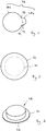
- a coupling element 48 which has, for example, a circular extent, and a bottom portion 62, which the coupling element 48 with a Handling section 64 (see FIG. 5 ) surmounted.
- the extension of the bottom section 62 deviates from the extent of the coupling element 48.
- the first punching element 54 has an in FIG. 6 schematically illustrated with a dashed line punching contour 72.
- the punch contour 72 extends between a region 74 and a region 76.
- the second punching element 56 has an in FIG. 6 punched contour 78 shown by a solid line, which is composed of a first contour portion 78a and a second contour portion 78b.
- the transitions between the contour sections 78a and 78b are arranged in the regions 74 and 76.
- the deviation of the profile of the contour section 78b from the course of the punch contour 72 determines the geometry and size of the handling section 64.
- the second punching element 56 has a self-contained punching contour 78, while the first punching element 54 has an open, not self-contained punching contour 72.
- the first punching element 54 serves to sever the flat body 42 in the region of a first partial circumference 55 (see FIG FIG. 5 ) of the coupling element 48.
- the partial circumference 55 of the coupling element 48 corresponds to the punching contour 72 of the first punching element 54 extending between the regions 74 and 76 (cf. FIG. 6 ).
- the second punching element 56 serves to sever the flat body 42 in the region of a second partial circumference 57 adjoining the first partial circumference 55 of the coupling element 48 (cf. FIG. 5 ).
- the partial circumference 57 of the coupling element 48 corresponds to the contour section 78a of the punching contour 78 of the second punching element 56 (cf. FIG. 6 ).
- the second punching element 56 In the area of the second partial circumference 57 of the coupling element 48, the second punching element 56 not only initially punches the flat body 42, but subsequently also the bottom 36 of the mold 16.
- the second contour section 78b of the second punching element 56 likewise initially pierces the flat body 42 and subsequently also the bottom 36 of the mold 16.
- the bottom section 62 punched out by the second punching element 56 with the two contour sections 78a and 78b projects beyond the coupling element 48 in the region of the handling section 64.
- FIG. 7 an alternative course for punching contours of the first punching element 54 and the second punching element 56 of the punching tool 52 is shown.
- the first punching element 54 has alternatively to a punching contour 72 according to FIG. 6 a self-contained, in FIG. 7 punched contour 80 shown with a dashed line.
- the second punching element 56 alternatively has a punched contour 78 according to FIG FIG. 6 one with a solid line illustrated punching contour 82.
- the punched contours 80 and / or 82 are, for example, circular.
- a circumferential, for example annular, handling section 64 can be produced, which projects beyond a coupling element 48 in all directions (cf. FIG. 8 ).
- a circumferential, for example annular, handling section 64 can be produced, which projects beyond a coupling element 48 in all directions (cf. FIG. 8 ).
- FIG. 8 additionally generates an annular material section, not shown in the drawing, which surrounds the coupling element 48. This material portion is formed in an annular space between the punching elements 54 and 56 and can be lifted and disposed of the flat body 42 of the annular handling portion 64 after removal / lifting of the punch 52.
- a plurality of punching tools 52 can advantageously be combined to form a punching tool arrangement in order to simultaneously cut out a plurality of coupling elements 48 from a flat body 42 in one punching operation.
- the mold 16 may be masked to avoid potential trapping of dust or other debris during the curing process. Furthermore, it is optionally possible, in particular before the removal of a coupling element 48 from the flat body 42, to lay a protective film on the already hardened or on the still to be hardened flat body 42.
- the protective element 70 or the protective elements protects or protects a coupling element 48 directly from its production and until immediately before the assembly of the coupling element 48 on the inside of a vehicle window, in which the coupling element 48 between the inside of a vehicle window and the coupling surface of an optical sensor is arranged.
Landscapes
- Engineering & Computer Science (AREA)
- Mechanical Engineering (AREA)
- Life Sciences & Earth Sciences (AREA)
- Forests & Forestry (AREA)
- Physics & Mathematics (AREA)
- Health & Medical Sciences (AREA)
- General Health & Medical Sciences (AREA)
- Optics & Photonics (AREA)
- Toxicology (AREA)
- Manufacturing & Machinery (AREA)
- Casting Or Compression Moulding Of Plastics Or The Like (AREA)
- Moulds For Moulding Plastics Or The Like (AREA)
Description
- Die Erfindung betrifft ein Verfahren und eine Vorrichtung zur Herstellung eines optischen Koppelelements aus Elastomer.
- Optische Koppelelemente der vorstehend genannten Art sind aus der
EP 2 130 727 A2 und derDE 10 2013 012 849 A1 bekannt und werden dazu verwendet, einen im Innenraum eines Fahrzeugs angeordneten optischen Sensor optisch mit der Fahrzeugscheibe zu koppeln. Für eine zuverlässige Funktion des Sensors ist es gewünscht, dass der Brechungsindex des für das Koppelelement verwendeten Materials dem Brechungsindex der Fahrzeugscheibe entspricht. Darüber hinaus ist es bevorzugt, dass die Transmission oder Durchlässigkeit des für das Koppelelement verwendeten Materials für Licht der relevanten Wellenlängen möglichst hoch ist. Dabei kann es sich je nach Anwendungsfall um - Licht im sichtbaren oder im unsichtbaren Spektralbereich handeln.
- Aufgrund der vorstehenden Anforderungen werden im Stand der Technik als Materialien für das Koppelelement Silikonmaterialien verwendet. Beispiele für solche Silikonmaterialien sind durch die
EP 2 181 023 B1 und dieEP 2 130 727 A2 offenbart, auch bekannt unter den Handelsbezeichnungen "Silgel 612" und "Semicosil 912". Derartige Materialien werden beispielsweise von der Firma Bayer oder von der Firma Wacker angeboten. - Die vorstehend genannten Materialien werden zur "in situ"-Herstellung von Koppelelementen verwendet, wobei zunächst fließfähiges und dann aushärtendes Material in einen Raum im Gehäuse des optischen Sensors eingebracht wird. Das Sensorgehäuse wird anschließend an der Scheibe befestigt, sodass das ausgehärte Silikonmaterial dann an der Scheibe anliegt. Eine solche Herstellung gestaltet sich sowohl bei der Erstmontage als auch bei der Reparatur einer Fahrzeugscheibe als aufwändig. Bei der Reparatur einer Fahrzeugscheibe oder eines Sensors kommt als Nachteil hinzu, dass das nicht formstabile Koppelelement zerstört wird und somit nicht wiederverwendbar ist.
- Eine Vorfertigung von Koppelelementen in eine Form ist allgemein aus den Dokumenten
EP 1 413 490 A2 undDE 10 2006 039 065 A1 bekannt. Genaue Angaben zur Herstellung sind jedoch aus diesen Dokumenten nicht bekannt. Hiervon ausgehend liegt der vorliegenden Erfindung die Aufgabe zugrunde, ein Verfahren und eine Vorrichtung anzugeben, welche eine einfache, preisgünstige und flexible Herstellung eines optischen Koppelelements ermöglichen. - Diese Aufgabe wird durch ein Verfahren gelöst, welches umfasst:
- Einfüllen einer fließfähigen Elastomerrezeptur oder von deren Bestandteilen in eine Form zur Herstellung eines Flachkörpers, dessen Dicke abgestimmt ist auf die Dicke eines herzustellenden Koppelelements,
- Aushärten zu einem formstabilen Elastomer,
- Austrennen einzelner Koppelelemente aus dem Flachkörper.
- Die vorstehend genannte Aufgabe wird auch durch eine Vorrichtung gelöst, welche umfasst: eine Form zum Einfüllen einer fließfähigen Elastomerrezeptur oder von deren Bestandteilen zur Herstellung eines Flachkörpers, dessen Dicke abgestimmt ist auf die Dicke eines herzustellenden Koppelelements, und ein Austrennwerkzeug zum Austrennen einzelner Koppelelemente aus dem Flachkörper.
- Erfindungsgemäß wird zunächst ein Flachkörper hergestellt, dessen Dicke in einfacher Weise dadurch beeinflusst werden kann, dass in die Form eine größere oder kleinere Menge fließfähige Elastomerrezeptur oder deren Bestandteile eingefüllt werden. Es wird also eine in Dickenrichtung eines Koppelelements gesehen einseitig offene Form verwendet, beispielsweise eine Wanne.
- Der Flachkörper erstreckt sich über eine größere Fläche, als es zur Herstellung eines einzelnen Koppelelements, vorzugsweise zur Herstellung mehrerer Koppelelemente, erforderlich ist. Da ein Austrennen einzelner Koppelelemente aus dem Flachkörper erfolgt, nachdem das Elastomer bereits ausgehärtet und formstabil ist, unterliegt ein aus dem Flachkörper ausgetrenntes Koppelelement keiner Schrumpfung mehr. Somit ist unabhängig von der für das Koppelelement verwendeten Rezeptur sichergestellt, dass die beim Austrennen des Koppelelements verwendete Kontur der Trennlinie exakt dem Umriss des fertigen Koppelelements entspricht.
- Wenn im Rahmen der vorliegenden Erfindung von "formstabil" die Rede ist, ist gemeint, dass ein Koppelelement einzeln handhabbar ist, sodass das Koppelelement gelagert und für eine Montage an einem optischen Sensor und/oder einer Fahrzeugscheibe bereitgehalten werden kann. Das formstabile Koppelelement wird also nicht "in situ" in oder auf dem Sensorgehäuse hergestellt.
- Bei einer Umstellung auf eine andere Elastomerrezeptur kann eine damit einhergehende Veränderung der Schrumpfung während des Aushärtevorgangs einfach durch Anpassung der Einfüllmenge in die Form ausgeglichen werden.
- Das erfindungsgemäße Verfahren ermöglicht es, Nachteile zu vermeiden, die mit einer im Prinzip ebenfalls denkbaren Herstellung eines optischen Koppelelements im Spritzgießverfahren (oder Reaktionsspritzgießverfahren) unter Verwendung eines geschlossenen Spritzgießwerkzeugs einhergehen. Beispielsweise müssen für unterschiedliche Koppelelemente mit unterschiedlichen Abmessungen nicht jeweils eigene und teure Spritzgießwerkzeuge bereitgestellt werden. Darüber hinaus ist es nicht erforderlich, Spritzgießwerkzeuge bereitzustellen, welche jeweils ein Übermaß aufweisen, das jeweils exakt an eine mit einem Aushärtevorgang einhergehende Schrumpfung angepasst ist. Da das Maß der Schrumpfung auch von den für die Elastomerrezeptur verwendeten Bestandteilen abhängig ist, kann eine Änderung der Bestandteile die Umarbeitung oder Neuherstellung eines Spritzgießwerkzeugs erforderlich machen.
- Im Rahmen der vorliegenden Erfindung kann nun eine besonders einfach aufgebaute Form verwendet werden, welche beispielsweise kreisförmig ist oder rechteckförmig. Dies wird dadurch ermöglicht, dass der Flachkörper flächenmäßig größer ist als mindestens ein Koppelelement und dass das Koppelelement aus dem Flachkörper nach Herstellung des Flachkörpers ausgetrennt wird.
- Vorzugsweise wird das erfindungsgemäße Koppelelement aus einem Silikonelastomer hergestellt, wobei zur Herstellung des Flachkörpers eine fließfähige Silikonrezeptur oder deren Bestandteile in die Form eingefüllt werden.
- Es ist möglich, die einzelnen Koppelelemente aus dem Flachkörper herauszutrennen, nachdem der aus ausgehärtetem, formstabilem Elastomer bestehende Flachkörper aus der Form entfernt wurde. Auf diese Weise kann die Form unmittelbar an den Aushärtevorgang anschließend wieder zur Herstellung eines weiteren Flachkörpers verwendet werden.
- Bei einer bevorzugten Ausführungsform der Erfindung ist es jedoch vorgesehen, dass das Austrennen einzelner Koppelelemente aus dem Flachkörper erfolgt, während der Flachkörper nach seinem Aushärten noch in der Form angeordnet ist. Dies vereinfacht die Handhabung des Flachkörpers während des Austrennvorgangs einzelner Koppelelemente.
- Eine weitere, bevorzugte Ausführungsform sieht vor, dass ein Bodenabschnitt des Bodens der Form ausgetrennt wird, wobei der Bodenabschnitt ein von dem Koppelelement ablösbares Schutzelement für die Unterseite des Koppelelements bildet. In diesem Zusammenhang ist es bevorzugt, dass die Austrennung eines Bodenabschnitts und die Austrennung eines Koppelelements simultan oder unmittelbar einander folgend durchgeführt wird, vorzugsweise unter Verwendung nur eines Stanzwerkzeugs.
- Ferner ist es bevorzugt, dass die Form aus einem Kunststoffmaterial hergestellt ist, welches einfacher durchtrennt werden kann, als ein im Prinzip auch denkbares metallisches Material. Bevorzugte Kunststoffmaterialien sind Polystyrol (PS), Acrylnitril-Butadien-Styrol (ABS), Polycarbonat (PC), Polymethylmethacrylat (PMMA), Polyethylenterephthalat (PET), Polybutylenterephthalat (PBT), Polyethylen (PE), Polypropylen (PP), Silikon oder dergleichen. Ein Kunststoffmaterial hat darüber hinaus den Vorteil, besonders preisgünstig zu sein, wobei der Materialeinsatz für eine einzelne Form in Abhängigkeit von der Größe der Form für mehrere Koppelelemente genügt. Ein zwangsweise anfallender Verschnitt kann stofflich wiederverwendet werden, insbesondere bei Verwendung von thermoplastischen Kunststoffmaterialien.
- Der Bodenabschnitt haftet an dem Koppelelement und kann unmittelbar vor dessen Montage an einer Fahrzeugscheibe entfernt werden. Auf diese Weise ist zumindest die Unterseite des Koppelelements gegen Verschmutzung und/oder mechanische Einflüsse geschützt. Darüber hinaus bildet der Bodenabschnitt einen stabilen Träger für das Koppelelement.
- Es ist möglich, dass der Bodenabschnitt und das Koppelelement identisch große Flächen aufweisen. Dies hat den Vorteil, dass der Austrennvorgang zum Austrennen eines Koppelelements aus dem Flachkörper und zum Austrennen eines Bodenabschnitts aus dem Boden der Form sich besonders einfach gestaltet.
- Eine bevorzugte Variante der Erfindung sieht jedoch vor, dass der Bodenabschnitt das Koppelelement mit mindestens einem Handhabungsabschnitt flächenmäßig überragt. Dies hat den Vorteil, dass der Bodenabschnitt an dem Handhabungsabschnitt ergriffen werden kann und das Schutzelement in einfacher Weise von dem Koppelelement entfernt werden kann, ohne dass es hierbei zu einem Berührkontakt mit einer optisch wirksamen Oberfläche des Koppelelements kommt.
- Im Rahmen der Erfindung bevorzugte Möglichkeiten des Austrennens des Koppelelements und/oder des Bodenabschnitts sind Ausstanzen, Wasser- oder Laserstrahlschneiden. Diese Verfahrensmöglichkeiten bestehen sowohl für den Fall, dass der Flachkörper nach Aushärten zu einem Elastomer aus der Form entfernt wird, als auch für den Fall, dass der Flachkörper während des Austrennens einzelner Koppelelemente in der Form verbleibt. Für den Fall, dass der Flachkörper während des Austrennens in der Form verbleibt, können unterschiedliche Abmessungen von Bodenabschnitt und Koppelelement dadurch erzielt werden, dass die Leistung des Wasser- oder Laserstrahls in entsprechender Weise angepasst wird. Zur Erzeugung ausschließlich einer Trennkontur des Koppelelements genügen niedrigere Leistungen; zur Herstellung einer auch den Boden der Form durchdringenden Trennlinie kann die Leistung erhöht werden.
- Eine besonders einfache Möglichkeit des Austrennens eines Koppelelements und/oder eines Bodenabschnitts ist jedoch das Ausstanzen. Dementsprechend ist ein bevorzugtes Austrennwerkzeug ein Stanzwerkzeug.
- Besonders bevorzugt ist es, wenn das Stanzwerkzeug zwei in Stanzrichtung gesehen zueinander versetzte Stanzelemente aufweist, wobei ein erstes Stanzelement zur zumindest anteiligen Austrennung eines Koppelelements aus dem Flachkörper dient und wobei ein zweites Stanzelement zur Durchtrennung des Flachkörpers und zum Austrennen eines Bodenabschnitts des Bodens der Form dient.
- Insbesondere dient ein erstes Stanzelement zur Durchtrennung eines ersten Koppelelementabschnitts eines Koppelelements aus dem Flachkörper, während ein zweites Stanzelement zeitlich einander folgend erst zur Durchtrennung eines an den ersten Koppelelementabschnitt angrenzenden zweiten Koppelelementabschnitts des Koppelelements und dann zum Austrennen eines Bodenabschnitts des Bodens der Form dient. In Stanzrichtung gesehen ist das erste Stanzelement gegenüber dem zweiten Stanzelement zurückversetzt, und zwar um ein Maß, das im Wesentlichen der Dicke des Bodens der Form entspricht.
- Insbesondere sind zwei zueinander versetzte Stanzelemente bevorzugt, wenn der Bodenabschnitt eine Unterseite des Koppelelements im Bereich eines Handhabungsabschnitts überragen soll.
- Bei einer weiteren Ausführungsform der Erfindung ist vorgesehen, dass eine Schutzfolie als von dem Koppelelement ablösbares Schutzelement für die Oberseite des Koppelelements verwendet wird. Eine solche Schutzfolie kann nachträglich auf ein bereits vereinzeltes Koppelelement aufgesetzt werden; es kann aber auch auf den bereits ausgehärteten oder noch nicht ausgehärteten Flachkörper aufgelegt werden, sodass auch diese Schutzfolie im Zuge der Austrennung des Koppelelements durch einen einfachen Austrennvorgang, insbesondere durch Stanzen, aber auch durch Wasser- oder Laserstrahlschneiden, vereinzelt werden kann.
- Auch für ein an der Oberseite des Koppelelements angeordnetes Schutzelement ist es bevorzugt, wenn ein Griffabschnitt vorgesehen ist, der das Ablösen des Schutzelements von dem Koppelelement vereinfacht. Bei diesem Griffabschnitt ist es jedoch bevorzugt, dass der Griffabschnitt separat von einer Folienschicht vorgesehen ist, beispielsweise nachträglich angebracht wird. Auf diese Weise kann ein Schutzfolienabschnitt, welcher flächenmäßig identisch ist zu dem Koppelelement, im Zuge des Austrennens des Koppelements aus dem Flachkörper hergestellt werden, nämlich indem das Austrennwerkzeug in einem Arbeitsgang die obere Schutzfolie und den Flachkörper durchtrennt.
- Bei einer erfindungsgemäßen Vorrichtung ist es ferner bevorzugt, wenn diese eine Ausrichteinrichtung zur Ausrichtung der Form in einer horizontalen Ebene aufweist. Auf diese Weise ist von einem Fertigungsort unabhängig gewährleistet, dass der Flachkörper eine über die Fläche hinweg konstante Dicke aufweist.
- Ferner ist bevorzugt, wenn die Vorrichtung eine Ansaugeinrichtung zur Fixierung der Form auf einer Aufstellfläche aufweist, um eine unabsichtliche Bewegung der Form, insbesondere während des Aushärtevorgangs, zu vermeiden. Besonders bevorzugt ist es, wenn die Ansaugeinrichtung in Form eines Vakuumtischs bereitgestellt wird, welcher eine werkzeuglose Fixierung der Form ermöglicht. Die Vakuumtischplatte wiederum ist vorzugsweise mittels der vorstehend genannten Ausrichteinrichtung ausrichtbar.
- Weitere Merkmale und Vorteile der Erfindung sind Gegenstand der nachfolgenden Beschreibung und der zeichnerischen Darstellung eines bevorzugten Ausführungsbeispiels.
- In der Zeichnung zeigt
- Fig. 1
- eine perspektivische Explosionsdarstellung einer Ausführungsform einer Vorrichtung zur Herstellung eines optischen Koppelelements aus Elastomer;
- Fig. 2
- eine perspektivische Ansicht der Vorrichtung gemäß
Fig. 1 ; - Fig. 3
- eine Draufsicht auf einen Teil der Vorrichtung und ein Stanzwerkzeug;
- Fig. 4
- eine Seitenansicht längs einer in
Fig. 3 mit IV - IV bezeichneten Schnittebene; - Fig. 5
- eine perspektivische Ansicht eines optischen Koppelelements mit einem bodenseitig angeordneten Schutzelement;
- Fig. 6
- eine schematische Ansicht des Verlaufs der Stanzkonturen des in den
Figuren 3 und 4 dargestellten Stanzwerkzeugs; - Fig. 7
- eine schematische Ansicht eines alternativen Verlaufs der Stanzkonturen des in den
Figuren 3 und 4 dargestellten Stanzwerkzeugs; und - Fig. 8
- eine perspektivische Ansicht eines optischen Koppelelements mit einem bodenseitig angeordneten Schutzelement, hergestellt unter Verwendung eines Stanzwerkzeugs mit Stanzkonturen gemäß
Figur 7 . - Eine Ausführungsform einer Vorrichtung zur Herstellung eines optischen Koppelelements aus Elastomer ist in der Zeichnung insgesamt mit dem Bezugszeichen 10 bezeichnet. Die Vorrichtung 10 umfasst eine Ausrichteinrichtung 12 zur Anordnung einer Ansaugeinrichtung 14, welche wiederum zur Fixierung einer Form 16 dient. Die Vorrichtung umfasst eine optionale Abdeckplatte 18, welche zur Abdeckung der Form 16 dient, ohne dabei in Kontakt mit einem in die Form 16 einzufüllenden Material zu gelangen.
- Die Ausrichteinrichtung 12 weist eine bodenseitige Grundplatte 20 zur Anordnung auf einem Tisch oder einer Raumbodenfläche auf. Ferner umfasst die Ausrichteinrichtung 12 eine Stellplatte 22, welche mittels Stellelementen 24 in ihrer Neigung relativ zu der Grundplatte 20 einstellbar ist. Vorzugsweise sind drei zueinander beabstandete Stellelemente 24 vorgesehen, die gemeinsam eine Stellebene aufspannen. Die Stellelemente 24 ermöglichen es, die Stellplatte 22 in einer exakt horizontalen Lage auszurichten.
- Die Stellplatte 22 dient zur Auflage der Ansaugeinrichtung 14. Diese ist in Form einer Vakuum- oder Hohlplatte 26 ausgebildet und weist an ihrer Oberseite Lufteintrittsöffnungen 28 auf, welche über einen Hohlraum 30 mit einem Vakuumanschluss 32 kommunizieren.
- Es ist möglich, jedoch nicht zwingend, dass auf der Oberseite der Platte 26 Positionierelemente 34 angeordnet sind, welche als Anschlag für die Form 16 und/oder als Libellen zur Prüfung der horizontalen Ausrichtung ausgebildet sind.
- Die Form 16 weist einen ebenen Boden 36 auf, welcher an seiner Berandung in eine umfangsseitig umlaufende Seitenwand 38 übergeht. Optional kann am oberen Rand der Seitenwand 38 ein sich im Wesentlichen parallel zu dem Boden erstreckender Kragen 40 vorgesehen sein. Dieser stabilisiert die Form 16 und dient zur Auflage einer unterseitigen Randfläche der optionalen Abdeckplatte 18.
- Im montierten Zustand der Vorrichtung (siehe
Figur 2 ) ist die Form 16 über die Stellplatte 22 exakt horizontal ausgerichtet. Ferner ist die Ansaugeinrichtung 14 fest mit der Stellplatte 22 verbunden. Die Form 16 ist an der Ansaugeinrichtung 14 fixiert, indem an den Vakuumanschluss 32 Vakuum angelegt wird. Die Seitenwand 38 der Form 16 liegt an den Positionierelementen 34 an. - Zur Herstellung eines Koppelelements wird die Form 16 mit einer fließfähigen, noch nicht ausgehärteten Silikonrezeptur oder mit deren Bestandteilen gefüllt. Dabei ist die Füllmenge so bemessen, dass ein in der Form 16 nach Aushärtung entstehender formstabiler Flachkörper 42 eine Dicke 44 aufweist (vergleiche
Figur 4 ), welche einer Dicke 46 eines aus dem Flachkörpern auszutrennenden Koppelelements 48 (vergleicheFigur 5 ) entspricht. Wenn das verwendete Material schwindungs- oder schrumpffrei ist, ist die Füllhöhe des fließfähigen Materials identisch gleich der Dicke 44 des Flachkörpers 42 nach Aushärtung zu einem formstabilen Silikonelastomer. Sofern während oder nach der Aushärtung eine Schrumpfung oder ein Schwinden stattfindet, ist die Einfüllhöhe des fließfähigen Materials der Schwindung entsprechend höher als die Dicke 44 des Flachkörpers 42. - Um ein einzelnes Koppelelement 48 aus dem Flachkörper 42 herauszutrennen, wird vorzugsweise ein Austrennwerkzeug 50 in Form eines Stanzwerkzeugs 52 verwendet. Insbesondere verbleibt der Flachkörper 42 während des Austrennens eines Koppelelements in der Form 16.
- Das Stanzwerkzeug 52 weist mindestens ein Stanzelement, vorzugsweise zwei Stanzelemente 54, 56 auf. Ein erstes Stanzelement 54 ist in einer Stanzrichtung 58 gesehen bezogen auf ein zweites Stanzelement 56 zurückversetzt. Das Maß der Zurückversetzung entspricht einer Dicke 60 des Bodens 36 der Form 16. Auf diese Weise ist es möglich, in nur einem Stanzvorgang gleichzeitig ein Koppelelement 48 auszutrennen, welches beispielsweise eine kreisförmige Erstreckung hat, und einen Bodenabschnitt 62, welcher das Koppelelement 48 mit einem Handhabungsabschnitt 64 (vergleiche
Figur 5 ) überragt. Im Bereich des Handhabungsabschnitts 64 weicht die Erstreckung des Bodenabschnitts 62 von der Erstreckung des Koppelelements 48 ab. - Das erste Stanzelement 54 weist eine in
Figur 6 schematisch mit einer gestrichelten Linie dargestellte Stanzkontur 72 auf. Die Stanzkontur 72 erstreckt sich zwischen einem Bereich 74 und einem Bereich 76. - Das zweite Stanzelement 56 weist eine in
Figur 6 mit durchgezogener Linie dargestellte Stanzkontur 78 auf, welche sich aus einem ersten Konturabschnitt 78a und einem zweiten Konturabschnitt 78b zusammensetzt. Die Übergänge zwischen den Konturabschnitten 78a und 78b sind in den Bereichen 74 und 76 angeordnet. Die Abweichung des Verlaufs des Konturabschnitts 78b von dem Verlauf der Stanzkontur 72 bestimmt die Geometrie und Größe des Handhabungsabschnitts 64. - Das zweite Stanzelement 56 weist eine in sich geschlossene Stanzkontur 78 auf, während das erste Stanzelement 54 eine offene, nicht in sich geschlossene Stanzkontur 72 besitzt. Das erste Stanzelement 54 dient zur Durchtrennung des Flachkörpers 42 im Bereich eines ersten Teilumfangs 55 (vergleiche
Figur 5 ) des Koppelelements 48. Der Teilumfang 55 des Koppelelements 48 korrespondiert mit der sich zwischen den Bereichen 74 und 76 erstreckenden Stanzkontur 72 des ersten Stanzelements 54 (vergleicheFigur 6 ). - Das zweite Stanzelement 56 dient zur Durchtrennung des Flachkörpers 42 im Bereich eines an den ersten Teilumfang 55 des Koppelelements 48 angrenzenden zweiten Teilumfangs 57 (vergleiche
Figur 5 ). Der Teilumfang 57 des Koppelelements 48 korrespondiert mit dem Konturabschnitt 78a der Stanzkontur 78 des zweiten Stanzelements 56 (vergleicheFigur 6 ). - Das zweite Stanzelement 56 durchstanzt in dem Bereich des zweiten Teilumfangs 57 des Koppelelements 48 nicht nur zunächst den Flachkörper 42, sondern anschließend auch den Boden 36 der Form 16.
- Der zweite Konturabschnitt 78b des zweiten Stanzelements 56 durchstanzt ebenfalls zunächst den Flachkörper 42 und anschließend auch den Boden 36 der Form 16. Der von dem zweiten Stanzelement 56 mit den beiden Konturabschnitten 78a und 78b ausgestanzte Bodenabschnitt 62 überragt das Koppelelement 48 im Bereich des Handhabungsabschnitts 64.
- In
Figur 7 ist ein alternativer Verlauf für Stanzkonturen des ersten Stanzelements 54 und des zweiten Stanzelements 56 des Stanzwerkzeugs 52 dargestellt. Das erste Stanzelement 54 weist alternativ zu einer Stanzkontur 72 gemäßFigur 6 eine in sich geschlossene, inFigur 7 mit gestrichelter Linie dargestellte Stanzkontur 80 auf. Das zweite Stanzelement 56 weist alternativ zu einer Stanzkontur 78 gemäßFigur 6 eine mit durchgezogener Linie dargestellte Stanzkontur 82 auf. Die Stanzkonturen 80 und/oder 82 sind beispielsweise kreisförmig. - Da die Stanzkontur 82 die Stanzkontur 80 entlang des gesamten Umfangs der Stanzkontur 80 überragt, kann bei Verwendung eines Stanzwerkzeugs 52 mit solchen Konturen 80, 82 ein umlaufender, beispielsweise ringförmiger, Handhabungsabschnitt 64 hergestellt werden, der ein Koppelelement 48 flächenmäßig in allen Richtungen überragt (vergleiche
Figur 8 ). Im Zuge des Ausstanzens des Koppelelements 48 aus dem Formkörper 42 wird bei Herstellung einer Anordnung gemäßFigur 8 zusätzlich ein in der Zeichnung nicht dargestellter, ringförmiger Materialabschnitt erzeugt, der das Koppelelement 48 umgibt. Dieser Materialabschnitt entsteht in einem ringförmigen Zwischenraum zwischen den Stanzelementen 54 und 56 und kann nach Entfernen/Abheben des Stanzwerkzeugs 52 von dem Flachkörper 42 von dem ringförmigen Handhabungsabschnitt 64 abgehoben und entsorgt werden. - Mehrere Stanzwerkzeuge 52 können vorteilhaft zu einer Stanzwerkzeuganordnung zusammengefasst werden, um in einem Stanzvorgang gleichzeitig mehrere Koppelelemente 48 aus einem Flachkörper 42 auszutrennen.
- Optional kann die Form 16 nach Einfüllung des fließfähigen und auszuhärtenden Silikonmaterials mit der Abdeckplatte 18 abgedeckt werden, um einen potentiellen Einschluss von Staub oder anderen Fremdkörpern während des Aushärtevorgangs zu vermeiden. Ferner ist es optional möglich, insbesondere vor Austrennung eines Koppelelements 48 aus dem Flachkörper 42, eine Schutzfolie auf den bereits ausgehärteten oder auf den noch auszuhärtenden Flachkörper 42 zu legen.
- Im Zuge der Austrennung eines Koppelelements 48 wird unmittelbar zuvor die Schutzfolie mittels des Stanzwerkzeugs 52 durchtrennt, der an dem Koppelelement verbleibende Teil der Schutzfolie bildet dann ein Schutzelement für eine Oberseite 66 des Koppelelements 48. Eine Unterseite 68 des Koppelelements 48 ist durch den Bodenabschnitt 62 geschützt, welcher ein Schutzelement 70 bildet.
- Das Schutzelement 70 oder die Schutzelemente schützt oder schützen ein Koppelelement 48 unmittelbar ab dessen Herstellung und bis unmittelbar vor der Montage des Koppelelements 48 an der Innenseite einer Fahrzeugscheibe, bei der das Koppelelement 48 zwischen der Innenseite einer Fahrzeugscheibe und der Koppelfläche eines optischen Sensors angeordnet wird.
Claims (15)
- Verfahren zur Herstellung eines optischen Koppelelements (48) aus Elastomer, umfassend:- Einfüllen einer fließfähigen Elastomerrezeptur oder von deren Bestandteilen in eine Form (16) zur Herstellung eines Flachkörpers (42), dessen Dicke (44) abgestimmt ist auf die Dicke (46) eines herzustellenden Koppelelements (48),- Aushärten zu einem formstabilen Elastomer,- Austrennen einzelner Koppelelemente (48) aus dem Flachkörper (42).
- Verfahren nach Anspruch 1, dadurch gekennzeichnet, dass das Austrennen erfolgt, während der Flachkörper (42) in der Form (16) angeordnet ist.
- Verfahren nach einem der voranstehenden Ansprüche, dadurch gekennzeichnet, dass ein Bodenabschnitt (62) des Bodens (36) der Form (16) ausgetrennt wird, wobei der Bodenabschnitt (62) ein von dem Koppelelement (48) ablösbares Schutzelement (70) für eine Unterseite (68) des Koppelelements (48) bildet.
- Verfahren nach Anspruch 3, dadurch gekennzeichnet, dass der Bodenabschnitt (62) und das Koppelelement (48) identisch große Flächen aufweisen.
- Verfahren nach Anspruch 3, dadurch gekennzeichnet, dass der Bodenabschnitt (62) das Koppelelement (48) mit mindestens einem Handhabungsabschnitt (64) flächenmäßig überragt.
- Verfahren nach einem der voranstehenden Ansprüche, dadurch gekennzeichnet, dass das Austrennen durch Ausstanzen, Wasser- oder Laserstrahlschneiden erfolgt.
- Verfahren nach einem der voranstehenden Ansprüche, dadurch gekennzeichnet, dass eine Schutzfolie als von dem Koppelelement (48) ablösbares Schutzelement für eine Oberseite (66) des Koppelelements (48) verwendet wird.
- Verfahren nach Anspruch 7, dadurch gekennzeichnet, dass das Schutzelement mit einem Griffabschnitt versehen ist, der das Ablösen des Schutzelements von dem Koppelelement (48) vereinfacht.
- Vorrichtung (10) zur Herstellung eines optischen Koppelelements (48) aus Elastomer, umfassend eine Form (16) zum Einfüllen einer fließfähigen Elastomerrezeptur oder von deren Bestandteilen zur Herstellung eines Flachkörpers (42), dessen Dicke (44) abgestimmt ist auf die Dicke (46) eines herzustellenden Koppelelements (48), und ein Austrennwerkzeug (50) zum Austrennen einzelner Koppelelemente (48) aus dem Flachkörper (42).
- Vorrichtung (10) nach Anspruch 9, dadurch gekennzeichnet, dass die Form (16) aus einem Kunststoffmaterial hergestellt ist.
- Vorrichtung (10) nach Anspruch 9 oder 10, dadurch gekennzeichnet, dass das Austrennwerkzeug (50) ein Stanzwerkzeug (52) ist.
- Vorrichtung (10) nach Anspruch 11, dadurch gekennzeichnet, dass das Stanzwerkzeug (52) zwei in Stanzrichtung (58) gesehen zueinander versetzte Stanzelemente (54, 56) aufweist, wobei ein erstes Stanzelement (54) zur zumindest anteiligen Austrennung eines Koppelelements (48) aus dem Flachkörper (42) dient und wobei ein zweites Stanzelement (56) zur Durchtrennung des Flachkörpers (42) und zum Austrennen eines Bodenabschnitts (62) des Bodens (36) der Form (16) dient.
- Vorrichtung (10) nach Anspruch 12, dadurch gekennzeichnet, dass eine Stanzkontur (78, 82) des zweiten Stanzelements (56) eine Stanzkontur (72, 80) des ersten Stanzelements (54) flächenmäßig überragt.
- Vorrichtung (10) nach einem der Ansprüche 9 bis 13, dadurch gekennzeichnet, dass die Vorrichtung (10) eine Ausrichteinrichtung (12) zur Ausrichtung der Form (16) in einer horizontalen Ebene aufweist.
- Vorrichtung (10) nach einem der Ansprüche 9 bis 14, dadurch gekennzeichnet, dass die Vorrichtung (10) eine Ansaugeinrichtung (14) zur Fixierung der Form (16) auf einer Aufstellfläche aufweist.
Priority Applications (10)
| Application Number | Priority Date | Filing Date | Title |
|---|---|---|---|
| SI201530088T SI3085520T1 (sl) | 2015-04-22 | 2015-04-22 | Postopek in naprava za proizvodnjo optičnega sklopnega elementa izdelanega iz elastomera |
| EP15164586.8A EP3085520B1 (de) | 2015-04-22 | 2015-04-22 | Verfahren und vorrichtung zur herstellung eines optischen koppelelements aus elastomer |
| PL15164586T PL3085520T3 (pl) | 2015-04-22 | 2015-04-22 | Sposób i urządzenie do wytwarzania optycznego elementu sprzęgającego z elastomeru |
| ES15164586.8T ES2640634T3 (es) | 2015-04-22 | 2015-04-22 | Procedimiento y dispositivo para la fabricación de un elemento de acoplamiento óptico hecho de un elastómero |
| JP2017550680A JP6371484B2 (ja) | 2015-04-22 | 2016-04-18 | エラストマーから光学結合部材を製造する方法および装置 |
| AU2016251152A AU2016251152B2 (en) | 2015-04-22 | 2016-04-18 | Method and device for producing an optical coupling element made of elastomer |
| CN201680011403.3A CN107428093B (zh) | 2015-04-22 | 2016-04-18 | 用于由弹性体制作光学耦合元件的设备和方法 |
| PCT/EP2016/058481 WO2016169870A2 (de) | 2015-04-22 | 2016-04-18 | Verfahren und vorrichtung zur herstellung eines optischen koppelelements aus elastomer |
| US15/542,078 US10300636B2 (en) | 2015-04-22 | 2016-04-18 | Method and device for producing an optical coupling element made of elastomer |
| ZA2017/05017A ZA201705017B (en) | 2015-04-22 | 2017-07-24 | Method and device for producing an optical coupling element made of elastomer |
Applications Claiming Priority (1)
| Application Number | Priority Date | Filing Date | Title |
|---|---|---|---|
| EP15164586.8A EP3085520B1 (de) | 2015-04-22 | 2015-04-22 | Verfahren und vorrichtung zur herstellung eines optischen koppelelements aus elastomer |
Publications (2)
| Publication Number | Publication Date |
|---|---|
| EP3085520A1 EP3085520A1 (de) | 2016-10-26 |
| EP3085520B1 true EP3085520B1 (de) | 2017-07-19 |
Family
ID=53008312
Family Applications (1)
| Application Number | Title | Priority Date | Filing Date |
|---|---|---|---|
| EP15164586.8A Active EP3085520B1 (de) | 2015-04-22 | 2015-04-22 | Verfahren und vorrichtung zur herstellung eines optischen koppelelements aus elastomer |
Country Status (10)
| Country | Link |
|---|---|
| US (1) | US10300636B2 (de) |
| EP (1) | EP3085520B1 (de) |
| JP (1) | JP6371484B2 (de) |
| CN (1) | CN107428093B (de) |
| AU (1) | AU2016251152B2 (de) |
| ES (1) | ES2640634T3 (de) |
| PL (1) | PL3085520T3 (de) |
| SI (1) | SI3085520T1 (de) |
| WO (1) | WO2016169870A2 (de) |
| ZA (1) | ZA201705017B (de) |
Families Citing this family (1)
| Publication number | Priority date | Publication date | Assignee | Title |
|---|---|---|---|---|
| US11953343B2 (en) * | 2017-07-07 | 2024-04-09 | Marcy Enterprises, Inc. | Packaged sensor pad |
Citations (2)
| Publication number | Priority date | Publication date | Assignee | Title |
|---|---|---|---|---|
| EP1413490A2 (de) * | 2002-10-22 | 2004-04-28 | Robert Bosch Gmbh | Sensoreinrichtung sowie Montageverfahren für eine Sensoreinrichtung |
| DE102006039065A1 (de) * | 2005-08-25 | 2007-03-01 | Leopold Kostal Gmbh & Co. Kg | Befestigungsvorrichtung für einen optischen Sensor an einer Fahrzeugscheibe |
Family Cites Families (14)
| Publication number | Priority date | Publication date | Assignee | Title |
|---|---|---|---|---|
| US2200730A (en) * | 1937-09-17 | 1940-05-14 | Us Rubber Co | Rotary cutter |
| JPH04216911A (ja) * | 1990-12-17 | 1992-08-07 | Kanai Hiroyuki | 弾性樹脂製成形品の製造方法 |
| JP3320478B2 (ja) | 1993-02-23 | 2002-09-03 | 住友スリーエム株式会社 | 粘弾性体を備えた積層体製品の製造方法及び制振材 |
| JP2004265495A (ja) * | 2003-02-28 | 2004-09-24 | Tdk Corp | 光記録媒体製造装置 |
| JPWO2006104107A1 (ja) * | 2005-03-29 | 2008-09-11 | 京セラ株式会社 | 多結晶シリコン基板及びその製造方法、多結晶シリコンインゴット、光電変換素子、並びに光電変換モジュール |
| DE102007039776A1 (de) | 2007-08-23 | 2009-02-26 | Leopold Kostal Gmbh & Co. Kg | Optischer Koppelkörper |
| US8414646B2 (en) * | 2007-12-27 | 2013-04-09 | Forsight Labs, Llc | Intraocular, accommodating lens and methods of use |
| DE102008026997B4 (de) | 2008-06-05 | 2012-06-14 | PMA/Tools Division Autoglas-Zubehör AG | Verfahren und Schablone zum Aufbringen einer Haftschicht auf eine Sensorvorrichtung |
| US8491137B2 (en) * | 2008-09-19 | 2013-07-23 | Magna Mirrors Of America, Inc. | Vehicle mirror assembly with wide angle element |
| JP2011046774A (ja) * | 2009-08-25 | 2011-03-10 | Bridgestone Corp | エネルギー線硬化型エラストマー組成物 |
| DE102011010971A1 (de) * | 2011-02-10 | 2012-08-16 | Leonhard Kurz Stiftung & Co. Kg | Formwerkzeug zum Hinterspritzen einer Kunststofffolie mit einer Kunststoffschmelze |
| JP6275945B2 (ja) * | 2012-12-10 | 2018-02-07 | 日東電工株式会社 | 両面粘着剤付き光学フィルム、およびそれを用いた画像表示装置の製造方法 |
| DE102012025132A1 (de) * | 2012-12-21 | 2014-06-26 | Ferromatik Milacron Gmbh | Verfahren zum Herstellen eines Kunststoff-Formteils sowie Spritzgießmaschine |
| DE102013012849B4 (de) * | 2013-08-02 | 2023-11-16 | HELLA GmbH & Co. KGaA | Optischer Sensor zur Montage an einer Scheibe und Verfahren zur Herstellung eines solchen optischen Sensors |
-
2015
- 2015-04-22 ES ES15164586.8T patent/ES2640634T3/es active Active
- 2015-04-22 SI SI201530088T patent/SI3085520T1/sl unknown
- 2015-04-22 PL PL15164586T patent/PL3085520T3/pl unknown
- 2015-04-22 EP EP15164586.8A patent/EP3085520B1/de active Active
-
2016
- 2016-04-18 AU AU2016251152A patent/AU2016251152B2/en active Active
- 2016-04-18 CN CN201680011403.3A patent/CN107428093B/zh active Active
- 2016-04-18 WO PCT/EP2016/058481 patent/WO2016169870A2/de active Application Filing
- 2016-04-18 US US15/542,078 patent/US10300636B2/en active Active
- 2016-04-18 JP JP2017550680A patent/JP6371484B2/ja active Active
-
2017
- 2017-07-24 ZA ZA2017/05017A patent/ZA201705017B/en unknown
Patent Citations (2)
| Publication number | Priority date | Publication date | Assignee | Title |
|---|---|---|---|---|
| EP1413490A2 (de) * | 2002-10-22 | 2004-04-28 | Robert Bosch Gmbh | Sensoreinrichtung sowie Montageverfahren für eine Sensoreinrichtung |
| DE102006039065A1 (de) * | 2005-08-25 | 2007-03-01 | Leopold Kostal Gmbh & Co. Kg | Befestigungsvorrichtung für einen optischen Sensor an einer Fahrzeugscheibe |
Also Published As
| Publication number | Publication date |
|---|---|
| ZA201705017B (en) | 2019-12-18 |
| US10300636B2 (en) | 2019-05-28 |
| WO2016169870A3 (de) | 2017-04-13 |
| CN107428093A (zh) | 2017-12-01 |
| CN107428093B (zh) | 2018-11-20 |
| EP3085520A1 (de) | 2016-10-26 |
| PL3085520T3 (pl) | 2017-12-29 |
| AU2016251152A1 (en) | 2017-09-21 |
| AU2016251152B2 (en) | 2018-03-01 |
| WO2016169870A2 (de) | 2016-10-27 |
| JP2018516776A (ja) | 2018-06-28 |
| JP6371484B2 (ja) | 2018-08-08 |
| ES2640634T3 (es) | 2017-11-03 |
| SI3085520T1 (sl) | 2017-10-30 |
| US20180001518A1 (en) | 2018-01-04 |
Similar Documents
| Publication | Publication Date | Title |
|---|---|---|
| EP1621313A1 (de) | Verfahren und Vorrichtung zur Herstellung eines Dekor-Zierteils mit freigestelltem Symbol und damit hergestelltem Dekor-Zierteil | |
| DE2952591A1 (de) | Verfahren zum fertigen von brandsohlen fuer schuhwerk | |
| DE102020005896A1 (de) | Verfahren zur Herstellung eines flächigen Verkleidungselementes für ein Fahrzeug | |
| EP1904282B1 (de) | Vorrichtung und verfahren zum entfernen eines längs erstreckten grates an einem formteil | |
| EP3022036B1 (de) | Verfahren zur herstellung eines formteils | |
| EP2788158B1 (de) | Verfahren und vorrichtung zum herstellen eines ausbrechwerkzeuges | |
| DE102013223982A1 (de) | Verfahren zum Herstellung von aus thermoplastischem Material gefertigten Teilen und entsprechende Formvorrichtung | |
| EP3085520B1 (de) | Verfahren und vorrichtung zur herstellung eines optischen koppelelements aus elastomer | |
| EP3046789A1 (de) | Luftfilter für eine belüftungseinrichtung eines kraftwagens und verfahren zu dessen einbau | |
| WO2007147470A1 (de) | Verfahren zu herstellung eines spritzgussteils mit integrierter flexibler leiterplatte | |
| DE2831619A1 (de) | Stanz- und rillwerkzeug | |
| DE4401903C1 (de) | Verfahren und Vorrichtung zum Kaschieren eines Bauteiles | |
| EP3600971B1 (de) | Anzeigeelement, verfahren zur herstellung eines anzeigeelements und verwendung eines anzeigeelements und fahrzeug mit einem anzeigeelement | |
| EP3222399B1 (de) | Vorrichtung und verfahren zum herstellen eines formpressteils, welches mindestens einen durchbruch aufweist | |
| DE4339480A1 (de) | Vorrichtung zum Ausstanzen von Formteilen aus einer Formteilbahn | |
| DE202015005807U1 (de) | Verbundbaustein, Verwendung und Verbundvorrichtung | |
| DE3131820A1 (de) | Verfahren zur herstellung einer verbundplatte | |
| EP3498961A1 (de) | Montageklotz | |
| EP0236910A1 (de) | Verfahren und Vorrichtung zur Herstellung von Faltschachteln | |
| DE102004056451A1 (de) | Werkzeug und Verfahren zur Herstellung von Formkörpern mit Öffnungen | |
| AT526547B1 (de) | Tragstab und Abdeckelement zur Bildung eines Gitterrostes | |
| DE102019122627B4 (de) | Verfahren zur Herstellung eines 2K-Kunststoffzierteils und 2K-Kunststoffzierteil | |
| DE102021102786B4 (de) | Verfahren zur Herstellung eines Produktes, insbesondere eines zahntechnischen Produktes | |
| DE102017101594A1 (de) | Kerze sowie Durchbrandsperre für eine Kerze | |
| DE19627387A1 (de) | Vorrichtung zum Hinterform-Pressen eines mit einer Dekorfolie zu versehenden Kunststoff-Trägerteiles |
Legal Events
| Date | Code | Title | Description |
|---|---|---|---|
| PUAI | Public reference made under article 153(3) epc to a published international application that has entered the european phase |
Free format text: ORIGINAL CODE: 0009012 |
|
| 17P | Request for examination filed |
Effective date: 20160331 |
|
| AK | Designated contracting states |
Kind code of ref document: A1 Designated state(s): AL AT BE BG CH CY CZ DE DK EE ES FI FR GB GR HR HU IE IS IT LI LT LU LV MC MK MT NL NO PL PT RO RS SE SI SK SM TR |
|
| AX | Request for extension of the european patent |
Extension state: BA ME |
|
| GRAP | Despatch of communication of intention to grant a patent |
Free format text: ORIGINAL CODE: EPIDOSNIGR1 |
|
| RIC1 | Information provided on ipc code assigned before grant |
Ipc: B29C 69/00 20060101AFI20170216BHEP Ipc: B60S 1/08 20060101ALI20170216BHEP Ipc: B29C 39/30 20060101ALN20170216BHEP Ipc: B26F 1/38 20060101ALI20170216BHEP |
|
| INTG | Intention to grant announced |
Effective date: 20170228 |
|
| RIC1 | Information provided on ipc code assigned before grant |
Ipc: B29C 69/00 20060101AFI20170217BHEP Ipc: B60S 1/08 20060101ALI20170217BHEP Ipc: B29C 39/30 20060101ALN20170217BHEP Ipc: B26F 1/38 20060101ALI20170217BHEP |
|
| GRAS | Grant fee paid |
Free format text: ORIGINAL CODE: EPIDOSNIGR3 |
|
| GRAA | (expected) grant |
Free format text: ORIGINAL CODE: 0009210 |
|
| AK | Designated contracting states |
Kind code of ref document: B1 Designated state(s): AL AT BE BG CH CY CZ DE DK EE ES FI FR GB GR HR HU IE IS IT LI LT LU LV MC MK MT NL NO PL PT RO RS SE SI SK SM TR |
|
| REG | Reference to a national code |
Ref country code: GB Ref legal event code: FG4D Free format text: NOT ENGLISH |
|
| REG | Reference to a national code |
Ref country code: CH Ref legal event code: EP |
|
| REG | Reference to a national code |
Ref country code: IE Ref legal event code: FG4D Free format text: LANGUAGE OF EP DOCUMENT: GERMAN |
|
| REG | Reference to a national code |
Ref country code: CH Ref legal event code: NV Representative=s name: DREISS PATENTANWAELTE PARTG MBB, DE Ref country code: AT Ref legal event code: REF Ref document number: 909967 Country of ref document: AT Kind code of ref document: T Effective date: 20170815 |
|
| REG | Reference to a national code |
Ref country code: DE Ref legal event code: R096 Ref document number: 502015001456 Country of ref document: DE |
|
| REG | Reference to a national code |
Ref country code: NL Ref legal event code: FP |
|
| REG | Reference to a national code |
Ref country code: ES Ref legal event code: FG2A Ref document number: 2640634 Country of ref document: ES Kind code of ref document: T3 Effective date: 20171103 |
|
| REG | Reference to a national code |
Ref country code: LT Ref legal event code: MG4D |
|
| PG25 | Lapsed in a contracting state [announced via postgrant information from national office to epo] |
Ref country code: NO Free format text: LAPSE BECAUSE OF FAILURE TO SUBMIT A TRANSLATION OF THE DESCRIPTION OR TO PAY THE FEE WITHIN THE PRESCRIBED TIME-LIMIT Effective date: 20171019 Ref country code: SE Free format text: LAPSE BECAUSE OF FAILURE TO SUBMIT A TRANSLATION OF THE DESCRIPTION OR TO PAY THE FEE WITHIN THE PRESCRIBED TIME-LIMIT Effective date: 20170719 Ref country code: LT Free format text: LAPSE BECAUSE OF FAILURE TO SUBMIT A TRANSLATION OF THE DESCRIPTION OR TO PAY THE FEE WITHIN THE PRESCRIBED TIME-LIMIT Effective date: 20170719 Ref country code: HR Free format text: LAPSE BECAUSE OF FAILURE TO SUBMIT A TRANSLATION OF THE DESCRIPTION OR TO PAY THE FEE WITHIN THE PRESCRIBED TIME-LIMIT Effective date: 20170719 Ref country code: FI Free format text: LAPSE BECAUSE OF FAILURE TO SUBMIT A TRANSLATION OF THE DESCRIPTION OR TO PAY THE FEE WITHIN THE PRESCRIBED TIME-LIMIT Effective date: 20170719 |
|
| PG25 | Lapsed in a contracting state [announced via postgrant information from national office to epo] |
Ref country code: RS Free format text: LAPSE BECAUSE OF FAILURE TO SUBMIT A TRANSLATION OF THE DESCRIPTION OR TO PAY THE FEE WITHIN THE PRESCRIBED TIME-LIMIT Effective date: 20170719 Ref country code: IS Free format text: LAPSE BECAUSE OF FAILURE TO SUBMIT A TRANSLATION OF THE DESCRIPTION OR TO PAY THE FEE WITHIN THE PRESCRIBED TIME-LIMIT Effective date: 20171119 Ref country code: LV Free format text: LAPSE BECAUSE OF FAILURE TO SUBMIT A TRANSLATION OF THE DESCRIPTION OR TO PAY THE FEE WITHIN THE PRESCRIBED TIME-LIMIT Effective date: 20170719 |
|
| REG | Reference to a national code |
Ref country code: GR Ref legal event code: EP Ref document number: 20170402597 Country of ref document: GR Effective date: 20180309 |
|
| REG | Reference to a national code |
Ref country code: DE Ref legal event code: R097 Ref document number: 502015001456 Country of ref document: DE |
|
| REG | Reference to a national code |
Ref country code: FR Ref legal event code: PLFP Year of fee payment: 4 |
|
| PG25 | Lapsed in a contracting state [announced via postgrant information from national office to epo] |
Ref country code: CZ Free format text: LAPSE BECAUSE OF FAILURE TO SUBMIT A TRANSLATION OF THE DESCRIPTION OR TO PAY THE FEE WITHIN THE PRESCRIBED TIME-LIMIT Effective date: 20170719 Ref country code: DK Free format text: LAPSE BECAUSE OF FAILURE TO SUBMIT A TRANSLATION OF THE DESCRIPTION OR TO PAY THE FEE WITHIN THE PRESCRIBED TIME-LIMIT Effective date: 20170719 |
|
| PLBE | No opposition filed within time limit |
Free format text: ORIGINAL CODE: 0009261 |
|
| STAA | Information on the status of an ep patent application or granted ep patent |
Free format text: STATUS: NO OPPOSITION FILED WITHIN TIME LIMIT |
|
| PG25 | Lapsed in a contracting state [announced via postgrant information from national office to epo] |
Ref country code: EE Free format text: LAPSE BECAUSE OF FAILURE TO SUBMIT A TRANSLATION OF THE DESCRIPTION OR TO PAY THE FEE WITHIN THE PRESCRIBED TIME-LIMIT Effective date: 20170719 Ref country code: SK Free format text: LAPSE BECAUSE OF FAILURE TO SUBMIT A TRANSLATION OF THE DESCRIPTION OR TO PAY THE FEE WITHIN THE PRESCRIBED TIME-LIMIT Effective date: 20170719 Ref country code: SM Free format text: LAPSE BECAUSE OF FAILURE TO SUBMIT A TRANSLATION OF THE DESCRIPTION OR TO PAY THE FEE WITHIN THE PRESCRIBED TIME-LIMIT Effective date: 20170719 |
|
| 26N | No opposition filed |
Effective date: 20180420 |
|
| PG25 | Lapsed in a contracting state [announced via postgrant information from national office to epo] |
Ref country code: MT Free format text: LAPSE BECAUSE OF FAILURE TO SUBMIT A TRANSLATION OF THE DESCRIPTION OR TO PAY THE FEE WITHIN THE PRESCRIBED TIME-LIMIT Effective date: 20170719 |
|
| PG25 | Lapsed in a contracting state [announced via postgrant information from national office to epo] |
Ref country code: MC Free format text: LAPSE BECAUSE OF FAILURE TO SUBMIT A TRANSLATION OF THE DESCRIPTION OR TO PAY THE FEE WITHIN THE PRESCRIBED TIME-LIMIT Effective date: 20170719 |
|
| REG | Reference to a national code |
Ref country code: IE Ref legal event code: MM4A |
|
| PG25 | Lapsed in a contracting state [announced via postgrant information from national office to epo] |
Ref country code: LU Free format text: LAPSE BECAUSE OF NON-PAYMENT OF DUE FEES Effective date: 20180422 |
|
| PG25 | Lapsed in a contracting state [announced via postgrant information from national office to epo] |
Ref country code: IE Free format text: LAPSE BECAUSE OF NON-PAYMENT OF DUE FEES Effective date: 20180422 |
|
| PG25 | Lapsed in a contracting state [announced via postgrant information from national office to epo] |
Ref country code: TR Free format text: LAPSE BECAUSE OF FAILURE TO SUBMIT A TRANSLATION OF THE DESCRIPTION OR TO PAY THE FEE WITHIN THE PRESCRIBED TIME-LIMIT Effective date: 20170719 |
|
| PG25 | Lapsed in a contracting state [announced via postgrant information from national office to epo] |
Ref country code: PT Free format text: LAPSE BECAUSE OF FAILURE TO SUBMIT A TRANSLATION OF THE DESCRIPTION OR TO PAY THE FEE WITHIN THE PRESCRIBED TIME-LIMIT Effective date: 20170719 |
|
| PG25 | Lapsed in a contracting state [announced via postgrant information from national office to epo] |
Ref country code: CY Free format text: LAPSE BECAUSE OF FAILURE TO SUBMIT A TRANSLATION OF THE DESCRIPTION OR TO PAY THE FEE WITHIN THE PRESCRIBED TIME-LIMIT Effective date: 20170719 Ref country code: HU Free format text: LAPSE BECAUSE OF FAILURE TO SUBMIT A TRANSLATION OF THE DESCRIPTION OR TO PAY THE FEE WITHIN THE PRESCRIBED TIME-LIMIT; INVALID AB INITIO Effective date: 20150422 Ref country code: MK Free format text: LAPSE BECAUSE OF NON-PAYMENT OF DUE FEES Effective date: 20170719 Ref country code: RO Free format text: LAPSE BECAUSE OF FAILURE TO SUBMIT A TRANSLATION OF THE DESCRIPTION OR TO PAY THE FEE WITHIN THE PRESCRIBED TIME-LIMIT Effective date: 20170719 |
|
| PG25 | Lapsed in a contracting state [announced via postgrant information from national office to epo] |
Ref country code: AL Free format text: LAPSE BECAUSE OF FAILURE TO SUBMIT A TRANSLATION OF THE DESCRIPTION OR TO PAY THE FEE WITHIN THE PRESCRIBED TIME-LIMIT Effective date: 20170719 |
|
| REG | Reference to a national code |
Ref country code: AT Ref legal event code: MM01 Ref document number: 909967 Country of ref document: AT Kind code of ref document: T Effective date: 20200422 |
|
| PG25 | Lapsed in a contracting state [announced via postgrant information from national office to epo] |
Ref country code: AT Free format text: LAPSE BECAUSE OF NON-PAYMENT OF DUE FEES Effective date: 20200422 |
|
| PGFP | Annual fee paid to national office [announced via postgrant information from national office to epo] |
Ref country code: NL Payment date: 20220419 Year of fee payment: 8 |
|
| PGFP | Annual fee paid to national office [announced via postgrant information from national office to epo] |
Ref country code: BG Payment date: 20220414 Year of fee payment: 8 |
|
| PGFP | Annual fee paid to national office [announced via postgrant information from national office to epo] |
Ref country code: SI Payment date: 20220413 Year of fee payment: 8 Ref country code: GR Payment date: 20220419 Year of fee payment: 8 Ref country code: BE Payment date: 20220419 Year of fee payment: 8 |
|
| PGFP | Annual fee paid to national office [announced via postgrant information from national office to epo] |
Ref country code: PL Payment date: 20230322 Year of fee payment: 9 |
|
| P01 | Opt-out of the competence of the unified patent court (upc) registered |
Effective date: 20230515 |
|
| PGFP | Annual fee paid to national office [announced via postgrant information from national office to epo] |
Ref country code: IT Payment date: 20230428 Year of fee payment: 9 Ref country code: FR Payment date: 20230417 Year of fee payment: 9 Ref country code: ES Payment date: 20230517 Year of fee payment: 9 Ref country code: DE Payment date: 20230614 Year of fee payment: 9 Ref country code: CH Payment date: 20230502 Year of fee payment: 9 |
|
| PGFP | Annual fee paid to national office [announced via postgrant information from national office to epo] |
Ref country code: GB Payment date: 20230424 Year of fee payment: 9 |
|
| REG | Reference to a national code |
Ref country code: NL Ref legal event code: MM Effective date: 20230501 |
|
| REG | Reference to a national code |
Ref country code: BE Ref legal event code: MM Effective date: 20230430 |
|
| PG25 | Lapsed in a contracting state [announced via postgrant information from national office to epo] |
Ref country code: GR Free format text: LAPSE BECAUSE OF NON-PAYMENT OF DUE FEES Effective date: 20231110 |
|
| PG25 | Lapsed in a contracting state [announced via postgrant information from national office to epo] |
Ref country code: SI Free format text: LAPSE BECAUSE OF NON-PAYMENT OF DUE FEES Effective date: 20230423 Ref country code: NL Free format text: LAPSE BECAUSE OF NON-PAYMENT OF DUE FEES Effective date: 20230501 Ref country code: GR Free format text: LAPSE BECAUSE OF NON-PAYMENT OF DUE FEES Effective date: 20231110 |
|
| PG25 | Lapsed in a contracting state [announced via postgrant information from national office to epo] |
Ref country code: BE Free format text: LAPSE BECAUSE OF NON-PAYMENT OF DUE FEES Effective date: 20230430 |
|
| REG | Reference to a national code |
Ref country code: SI Ref legal event code: KO00 Effective date: 20240115 |