EP2669746B1 - Bilderzeugungsvorrichtung - Google Patents
Bilderzeugungsvorrichtung Download PDFInfo
- Publication number
- EP2669746B1 EP2669746B1 EP13169566.0A EP13169566A EP2669746B1 EP 2669746 B1 EP2669746 B1 EP 2669746B1 EP 13169566 A EP13169566 A EP 13169566A EP 2669746 B1 EP2669746 B1 EP 2669746B1
- Authority
- EP
- European Patent Office
- Prior art keywords
- opening
- image forming
- forming apparatus
- support member
- closing portion
- Prior art date
- Legal status (The legal status is an assumption and is not a legal conclusion. Google has not performed a legal analysis and makes no representation as to the accuracy of the status listed.)
- Not-in-force
Links
- 238000000034 method Methods 0.000 claims description 35
- 238000011144 upstream manufacturing Methods 0.000 claims description 6
- 230000015572 biosynthetic process Effects 0.000 claims description 3
- 238000012546 transfer Methods 0.000 description 12
- 238000011161 development Methods 0.000 description 9
- 238000012423 maintenance Methods 0.000 description 6
- 108091008695 photoreceptors Proteins 0.000 description 4
- 238000004140 cleaning Methods 0.000 description 3
- 230000002093 peripheral effect Effects 0.000 description 3
- 238000000926 separation method Methods 0.000 description 2
- 230000001174 ascending effect Effects 0.000 description 1
- 238000007796 conventional method Methods 0.000 description 1
- 230000003292 diminished effect Effects 0.000 description 1
- 230000000694 effects Effects 0.000 description 1
- 238000010438 heat treatment Methods 0.000 description 1
- 238000009434 installation Methods 0.000 description 1
- 230000001105 regulatory effect Effects 0.000 description 1
- 230000000717 retained effect Effects 0.000 description 1
Images




Classifications
-
- G—PHYSICS
- G03—PHOTOGRAPHY; CINEMATOGRAPHY; ANALOGOUS TECHNIQUES USING WAVES OTHER THAN OPTICAL WAVES; ELECTROGRAPHY; HOLOGRAPHY
- G03G—ELECTROGRAPHY; ELECTROPHOTOGRAPHY; MAGNETOGRAPHY
- G03G21/00—Arrangements not provided for by groups G03G13/00 - G03G19/00, e.g. cleaning, elimination of residual charge
- G03G21/16—Mechanical means for facilitating the maintenance of the apparatus, e.g. modular arrangements
- G03G21/18—Mechanical means for facilitating the maintenance of the apparatus, e.g. modular arrangements using a processing cartridge, whereby the process cartridge comprises at least two image processing means in a single unit
- G03G21/1803—Arrangements or disposition of the complete process cartridge or parts thereof
-
- G—PHYSICS
- G03—PHOTOGRAPHY; CINEMATOGRAPHY; ANALOGOUS TECHNIQUES USING WAVES OTHER THAN OPTICAL WAVES; ELECTROGRAPHY; HOLOGRAPHY
- G03G—ELECTROGRAPHY; ELECTROPHOTOGRAPHY; MAGNETOGRAPHY
- G03G15/00—Apparatus for electrographic processes using a charge pattern
- G03G15/01—Apparatus for electrographic processes using a charge pattern for producing multicoloured copies
- G03G15/0142—Structure of complete machines
- G03G15/0178—Structure of complete machines using more than one reusable electrographic recording member, e.g. one for every monocolour image
- G03G15/0189—Structure of complete machines using more than one reusable electrographic recording member, e.g. one for every monocolour image primary transfer to an intermediate transfer belt
-
- G—PHYSICS
- G03—PHOTOGRAPHY; CINEMATOGRAPHY; ANALOGOUS TECHNIQUES USING WAVES OTHER THAN OPTICAL WAVES; ELECTROGRAPHY; HOLOGRAPHY
- G03G—ELECTROGRAPHY; ELECTROPHOTOGRAPHY; MAGNETOGRAPHY
- G03G21/00—Arrangements not provided for by groups G03G13/00 - G03G19/00, e.g. cleaning, elimination of residual charge
- G03G21/16—Mechanical means for facilitating the maintenance of the apparatus, e.g. modular arrangements
- G03G21/1604—Arrangement or disposition of the entire apparatus
- G03G21/1623—Means to access the interior of the apparatus
- G03G21/1633—Means to access the interior of the apparatus using doors or covers
-
- G—PHYSICS
- G03—PHOTOGRAPHY; CINEMATOGRAPHY; ANALOGOUS TECHNIQUES USING WAVES OTHER THAN OPTICAL WAVES; ELECTROGRAPHY; HOLOGRAPHY
- G03G—ELECTROGRAPHY; ELECTROPHOTOGRAPHY; MAGNETOGRAPHY
- G03G21/00—Arrangements not provided for by groups G03G13/00 - G03G19/00, e.g. cleaning, elimination of residual charge
- G03G21/16—Mechanical means for facilitating the maintenance of the apparatus, e.g. modular arrangements
- G03G21/18—Mechanical means for facilitating the maintenance of the apparatus, e.g. modular arrangements using a processing cartridge, whereby the process cartridge comprises at least two image processing means in a single unit
- G03G21/1839—Means for handling the process cartridge in the apparatus body
- G03G21/1842—Means for handling the process cartridge in the apparatus body for guiding and mounting the process cartridge, positioning, alignment, locks
- G03G21/1853—Means for handling the process cartridge in the apparatus body for guiding and mounting the process cartridge, positioning, alignment, locks the process cartridge being mounted perpendicular to the axis of the photosensitive member
-
- G—PHYSICS
- G03—PHOTOGRAPHY; CINEMATOGRAPHY; ANALOGOUS TECHNIQUES USING WAVES OTHER THAN OPTICAL WAVES; ELECTROGRAPHY; HOLOGRAPHY
- G03G—ELECTROGRAPHY; ELECTROPHOTOGRAPHY; MAGNETOGRAPHY
- G03G2215/00—Apparatus for electrophotographic processes
- G03G2215/01—Apparatus for electrophotographic processes for producing multicoloured copies
- G03G2215/0103—Plural electrographic recording members
- G03G2215/0119—Linear arrangement adjacent plural transfer points
- G03G2215/0122—Linear arrangement adjacent plural transfer points primary transfer to an intermediate transfer belt
- G03G2215/0125—Linear arrangement adjacent plural transfer points primary transfer to an intermediate transfer belt the linear arrangement being horizontal or slanted
- G03G2215/0132—Linear arrangement adjacent plural transfer points primary transfer to an intermediate transfer belt the linear arrangement being horizontal or slanted vertical medium transport path at the secondary transfer
-
- G—PHYSICS
- G03—PHOTOGRAPHY; CINEMATOGRAPHY; ANALOGOUS TECHNIQUES USING WAVES OTHER THAN OPTICAL WAVES; ELECTROGRAPHY; HOLOGRAPHY
- G03G—ELECTROGRAPHY; ELECTROPHOTOGRAPHY; MAGNETOGRAPHY
- G03G2221/00—Processes not provided for by group G03G2215/00, e.g. cleaning or residual charge elimination
- G03G2221/16—Mechanical means for facilitating the maintenance of the apparatus, e.g. modular arrangements and complete machine concepts
- G03G2221/1678—Frame structures
- G03G2221/1684—Frame structures using extractable subframes, e.g. on rails or hinges
-
- G—PHYSICS
- G03—PHOTOGRAPHY; CINEMATOGRAPHY; ANALOGOUS TECHNIQUES USING WAVES OTHER THAN OPTICAL WAVES; ELECTROGRAPHY; HOLOGRAPHY
- G03G—ELECTROGRAPHY; ELECTROPHOTOGRAPHY; MAGNETOGRAPHY
- G03G2221/00—Processes not provided for by group G03G2215/00, e.g. cleaning or residual charge elimination
- G03G2221/16—Mechanical means for facilitating the maintenance of the apparatus, e.g. modular arrangements and complete machine concepts
- G03G2221/1678—Frame structures
- G03G2221/169—Structural door designs
Definitions
- the present invention relates to an image forming apparatus, for forming an image on a recording medium, to which a cartridge can be detachably attached.
- An image forming apparatus is configured to form an image on a recording medium by employing an image forming process such as an electrophotographic process, an electrostatic recording process, or a magnetic recording process.
- the image forming apparatus includes, for example, a copying machine, a printer (a light-emitting diode (LED) printer, a laser beam printer or the like), a facsimile apparatus, and a multifunction peripheral having the functions of the above-mentioned apparatuses.
- An image is formed on the recording medium by the image forming apparatus.
- the recording medium includes, for example, paper, an overhead transparency (OHT) sheet, or a label.
- the cartridge includes, for example, a process cartridge or a development cartridge, and contributes to an image forming process for forming an image on a recording medium while being detachably attached to the apparatus main body of the image forming apparatus.
- the apparatus main body refers to the components of the image forming apparatus excluding the cartridge.
- the process cartridge is formed by integrating an image bearing member, on which a latent image is to be formed, with at least one of the following units: a charging unit, a developing unit, a cleaning unit, etc., and is detachably attached to the apparatus main body.
- the image bearing member includes an electrophotographic photosensitive member for an electrophotographic process, an electrostatic recording dielectric for an electrostatic recording process, a magnetic recording magnetic member for a magnetic recording process or the like.
- the process cartridge can be attached and detached to and from the apparatus main body manually by the user. Thus, the maintenance of the apparatus main body is easy to perform.
- the process cartridge includes a cartridge in which an image bearing member is integrated with a process unit, and is detachably attached to an apparatus main body.
- the process cartridge in which the image bearing member and the developing unit are integrated is referred to as an integrated-type process cartridge.
- the process cartridge in which the image bearing member and a process unit excluding the developing unit is integrated is referred to as a separated-type process cartridge. That is, the separated-type process cartridge refers to a cartridge which performs image formation along with the development unit, which is provided separately from the process cartridge.
- the development cartridge includes a developing roller (developer bearing member) and contains developer (toner) used for developing a latent image formed on the image bearing member.
- the development cartridge is detachably attached to the apparatus main body.
- the development cartridge can also be attached and detached to and from the apparatus main body manually by the user. Thus, the maintenance of the apparatus main body is easy to perform.
- the image bearing member is mounted to the apparatus main body or a cartridge support member.
- the image bearing member is provided in the separated-type process cartridge (In this case, the process cartridge does not include the developing unit).
- the cartridge includes the integrated-type or the separated-type process cartridge. Further, the case is included where the separated-type process cartridge and the development cartridge are used together in pairs. Further, the case is included where the image bearing member is fixedly mounted to the apparatus main body or the cartridge support member, with the development cartridge being detachable so as to be capable of acting on the image bearing member. Further, the cartridge also includes a developer cartridge containing developer (toner) to be supplied to the process cartridge, the development cartridge, etc.
- an electrophotographic image forming apparatus employing electrophotography such as a printer will be used as an example for description.
- An electrophotographic photosensitive member serving as the image bearing member is uniformly charged, and a latent image is formed through selective exposure of the electrophotographic photosensitive member.
- the latent image is developed with the developer to be visualized as a developer image, and then the image is transferred to a recording medium. By applying heat and pressure to the transferred developer image, the image is fixed and recorded onto the recording image.
- Such an electrophotographic image forming apparatus involves the supply of developer and the maintenance of various process units .
- all or part of the electrophotographic photosensitive member, the charging unit, the developing unit, the cleaning unit, etc. are integrated into a frame as a cartridge.
- a cartridge system in which the cartridge is detachably attached to the apparatus main body of the electrophotographic image forming apparatus.
- this cartridge system the maintenance of the apparatus can be performed by the user in such a way as to replace the cartridge, thereby achieving a substantial improvement in terms of operability.
- this cartridge system is widely used in electrophotographic image forming apparatuses.
- an opening is provided vertically above the apparatus main body.
- the opening/closing member has a surface curved in an arcuate shape so that, when closed, the opening/closing member can cover an opening provided in the horizontal direction and the opening provided in the vertical direction.
- the present invention further improves the above-described conventional technique.
- JP2009031816A aims to provide an image forming apparatus which is equipped with an opening part in a housing and in/from which attachable/detachable components are loaded/unloaded through the opening part, and which is constituted to make it easy to access the inside of the housing and stably support the paper by the upper surface part of the housing.
- a paper placing part comprises a paper placing part main body arranged on a rear side, and an upper surface side cover part arranged on a front side, constituted to cover at least the front side of the upper surface of the opening part, having a front end set as a free end, and provided to be openable/closable in the main body part of the housing so as to turn centering around an axial line in a right-and-left direction set on a rear end side.
- JP2011158510A aims to provide an image forming apparatus which includes one or more image forming parts capable of forming toner images.
- An image forming apparatus is configured to primarily transfer further the toner image to an intermediate transfer belt; then to secondarily transfer the toner image to a paper ascending from a recording-paper supply part; further, to move the paper upward to pass through a fixing device and fix the secondarily-transferred toner image onto the paper; and then, to eject the paper S to a paper ejection tray.
- the image forming apparatus includes a side cover capable of opening/closing paper-ascending conveying paths from the paper supply part; and an upper cover capable of opening/closing an area, including the fixing device.
- An image reading device is externally attached to the image forming apparatus so as to be detachable above the fixing device.
- JP2012063795A aims to provide an electrophotographic image forming apparatus where a drawer member in which a photoreceptor drum and a developing unit are mounted is mounted in an apparatus body, which enables the photoreceptor drum and a developing roller to come into contact with each other and be separated from each other, and which achieves downsizing. It suggests an electrophotographic image forming apparatus comprising: a process cartridge; an apparatus body; and a drawer member which detachably supports the process cartridge, and is movable between an inside position located inside the apparatus body and an outside position located outside the apparatus body.
- a contact/separation member which can take a contact position for bringing a developing roller and a photoreceptor drum into contact with each other and a separation position for separating the developing roller and the photoreceptor drum from each other, is provided in the drawer member.
- the present invention is directed to an image forming apparatus in which a reduction in size is achieved while securing replaceability of a cartridge with respect to a cartridge support member.
- An electrophotographic image forming apparatus (hereinafter referred to as the image forming apparatus) 100 will be described.
- a color laser beam printer is illustrated as the image forming apparatus 100 as an example.
- the overall configuration and the function of the laser beam printer will be described.
- the image forming apparatus 100 is applicable not only to a full color laser beam printer but also to some other image forming apparatuses such as a color electrophotographic copying machine or a facsimile apparatus.
- Fig. 1 is a sectional view of the image forming apparatus 100 according to the first embodiment.
- the front side of an apparatus main body A (the front side of the main body) is the side where there is provided a door member 23, which is an opening/closing member provided to be openable and closable with respect to the apparatus main body A (the right-hand side in Fig. 1 ).
- the door member 23 moves between a closing position (illustrated in Fig. 1 ) covering an opening 22, which includes a first opening 22a and a second opening 22b provided in the apparatus main body A, and an opening position (illustrated in Fig. 2 ) opening the opening 22.
- a tray 20 passes through the opening 22 when the tray 20 moves between an inner position I (illustrated in Fig. 1 ) and an outer position O (illustrated in Fig. 2 ).
- the back side of the apparatus main body A (the rear side of the main body) is the side opposite the side where the door member 23 is provided and is the side where there is provided a feeding path 19 for a recording medium 6 (the left-hand side in Fig. 1 ).
- the apparatus main body A refers to the portion excluding, from the image forming apparatus 100, a tray 20 constituting the cartridge support member and process cartridges 4 (4y, 4m, 4c, and 4k) .
- a sheet feeding cassette 5 for accommodating sheets 6 serving as the recording media, a sheet feeding roller 7, an intermediate transfer belt 8, a fixing film 13 and a pressing roller 14 that are provided in a fixing unit 12, a laser scanner 18, etc.
- the tray 20 which is provided to be movable between the inner position I and the outer position O of the apparatus main body A with respect to the apparatus main body A, and which detachably supports the process cartridges 4 (4y, 4m, 4c, and 4k).
- the cartridges 4 integrally include photosensitive drums 1 (1y, 1m, 1c, and 1k), developing rollers 2 (2y, 2m, 2c, and 2k) as process units acting on the photosensitive drums 1, charging rollers 3 (3y, 3m, 3c, and 3k), and cleaning blades (not illustrated) .
- the cartridges 4 are detachably attached to the tray 20, and are attached to inner positions inside the apparatus main body A where image formation is possible.
- the sheets 6 stacked in the sheet feeding cassette 5 are fed by a sheet feeding roller 7 (illustrated in Fig. 1 ) configured to rotate clockwise, and are sent to a nip portion between a belt drive roller 10 and a transfer roller 9 (transfer portion) .
- the photosensitive drums 1 (illustrated in Fig. 1 ) start to rotate counterclockwise, and are charged on the outer peripheral surfaces thereof by the charging rollers 3.
- a laser beam emitted from a laser scanner 18 is applied to the charged photosensitive drums 1 in accordance with image information.
- electrostatic latent images are successively formed on the photosensitive drums 1.
- the electrostatic latent images are developed with developer by the developing roller 2.
- each of the cartridges 4 is of the same configuration, except that the color of developer differs for each cartridge and that the tank volume may differ for each cartridge.
- the cartridge 4y contains yellow developer, and forms a yellow developer image on the photosensitive drum 1y.
- the cartridge 4m contains magenta developer, and forms a magenta developer image on the photosensitive drum 1m.
- the cartridge 4c contains cyan developer, and forms a cyan developer image on the photosensitive drum 1c.
- the cartridge 4k contains black developer, and forms a black developer image on the photosensitive drum 1k.
- the developer images formed on the photosensitive drums 1 are transferred to an intermediate transfer belt 8.
- the intermediate transfer belt 8 is an endless belt configured to rotate while being in contact with the photosensitive drums 1.
- the intermediate transfer belt 8 is suspended by the belt drive roller 10 and a tension roller 11.
- the developer images transferred to the intermediate transfer belt 8 are secondarily transferred to a sheet 6 sent to the nip portion between the belt drive roller 10 and the transfer roller 9.
- the sheet 6 to which the developer images have been transferred is sent to the nip portion between a fixing film 13 and a pressure roller 14 to undergo heating and pressurization. As a result, the developer images are fixed onto the sheet 6.
- a black developer image is only formed on the photosensitive drum 1k, and is transferred to the sheet 6.
- the sheet 6 on which the developer images have been fixed is discharged by a discharge roller 15 and a discharge runner 16 to a sheet discharge unit 17.
- the tray 20 supported by a tray support member 24 is provided so as to be slidable, substantially in the horizontal direction through the opening 22, between the inner position I situated on the inner side of the apparatus main body A illustrated in Fig. 1 and the outer position O situated on the outer side of the apparatus main body A illustrated in Fig. 2 .
- the inner position I is the position at which the tray 20 is situated inside the apparatus main body A, that is, on the inner side of the door when the door member 23 is closed.
- the outer position O is the position at which the tray 20 is situated outside the apparatus main body A, that is, on the outer side of the opening 22. The user pulls out the tray 20 to the outer position O to perform the attachment/detachment and replacement of the cartridges 4 on the tray 20.
- the door member 23 opens and closes the opening 22 including the first opening 22a opening in the horizontal direction of the apparatus main body A and the second opening 22b opening in the vertical direction thereof. That is, the door member 23 includes a first opening/closing portion 23a for closing the first opening 22a and a second opening/closing portion 23b for closing the second opening 22b.
- the first opening/closing portion 23a includes a rotation center r1 on the lower side of the apparatus main body A, and is rotatably mounted to the apparatus main body A.
- the second opening/closing portion 23b has, when the door member 23 is closed, a rotation center r2 on the upper side of the first opening/closing portion 23a in a closed state, and is rotatably mounted to the apparatus main body A.
- An elastic member 28 (as shown in Figure 6B ) is mounted to the first opening/closing member 23a and to the rotation center r2 portion of the second opening/closing portion 23b.
- the second opening/closing portion 23b is biased with respect to the first/opening closing portion 23a so as to bias the second opening/closing portion 23b towards a protruding position (explained below) with respect to the first opening/closing portion 23a (upstream in the pull-out direction of the tray 20 in Fig. 3 ). Further, a lock member 25 illustrated in Fig. 6 is provided on the first opening/closing portion 23a.
- the lock member 25 is engaged with an engaged portion 23b1 of the second opening/closing portion 23b such that the second opening/closing portion 23b is retained in the protruding position at which the second opening/closing portion 23b protrudes into the movement path when the tray 20 is pulled out as illustrated in Fig. 6A .
- this protruding position is the position where the second opening/closing portion 23b closes the second opening 22b.
- the door member 23 is opened with the second opening/closing portion 23b being situated at the protruding position as illustrated in Fig. 3 .
- the door member 23 is opened, and the user grips a tray grip portion 27 to pull out the tray 20 as illustrated in Fig. 3 .
- the user pulls the tray 20 forwards with respect to the apparatus main body A.
- the tray 20 slides to the front side of the apparatus main body A from the tray support member 24 of the apparatus main body A along a first guide rail 23a1 (see Fig. 7 ) which is a first guide portion provided on the back side of the first opening/closing portion 23a and configured to guide the tray 20, and comes into contact with the second opening/closing portion 23b (see Fig. 3 ).
- the cartridge 4 on the downstream side in the pull-out direction is the black toner cartridge 4k, which is one of the plurality of cartridges 4 and whose replacement frequency is generally high.
- the attachment/detachment of the black cartridge 4k can be performed in this state.
- the tray 20 is further pulled out forwards.
- an abutment portion 25b of the lock member 25 provided at the first guide rail portion 23a1 of the first opening/closing portion 23a abuts the tray 20 to rotate the lock member 25.
- the engagement portion 25a of the lock member 25 is separated from the engaged portion 23a1 of the first opening/closing portion 23a to release the engagement.
- the second opening/closing portion 23b is retracted from the protruding position as illustrated in Fig. 6B , and moves to the retracted position, where the movement path for the tray 20 is open.
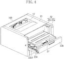
- a second guide rail 23b2 which is a second guide portion provided on the back side of the second opening/closing portion 23b, and the first guide rail 23a1 on the back side of the first opening/closing portion 23a, extend in a straight line in the pull-out direction of the tray 20. It becomes possible to move the tray 20 to the outer position O, where all the cartridges 4 can be attached and detached. At the outer position O, the user performs the attachment/detachment and replacement of the cartridges 4. As illustrated in the perspective view in Fig. 5 , the first opening 22a and the second opening 22b of the opening 22 of the apparatus main body A are open in the lower-right apparatus main body A in Fig.
- the tray 20 is regulated in the vertical direction and in the horizontal direction, thereby suppressing unnecessary movement of the tray 20 at the time of attachment/detachment of the cartridges 4. This can improve usability.
- the tray 20 When the tray 20 is pushed back to the apparatus main body A after the replacement of the cartridges 4, the tray 20 disappears on the second guide rail 23b2 of the second opening/closing portion 23b. Then, the second opening/closing portion 23b is urged by the elastic member 28 including a spring or the like to move towards the protruding position, whereby the engagement portion 25a of the lock member 25 is engaged with the engaged position 23b1 of the second opening/closing portion 23b, and the second opening/closing portion 23b is locked at the protruding position with respect to the first opening/closing portion 23a.
- the elastic member 28 including a spring or the like
- the user moves the tray 20 to the inner position of the apparatus main body A, and, by only closing the door member 23 in the state in which the first opening/closing portion 23a and the second opening/closing portion 23b are integrated, the operation of attaching the tray 20 is completed.
- the amount of pulling out of the tray 20 can be reduced while securing the replaceability of the cartridges 4 provided on the upstream side of the second opening 22b, which is open vertically above the apparatus main body A, in the pull-out direction of the tray 20.
- the second opening/closing portion 23b to be movable with respect the first opening/closing portion 23a, there is no need to greatly open the door member 23 in order to open the movement path of the tray 20. Accordingly, the size in the vertical direction (height) of the image forming apparatus 100 can be diminished. Further, as illustrated in Fig. 8 , even in the case where a cassette for large size sheets is attached to the apparatus main body A, the door member 23 does not interfere with the cassette at the opening position.
- the tray 20 is pulled out substantially in parallel to the main body.
- the same effect can also be achieved in a configuration in which the tray is pulled out from the apparatus main body obliquely downwards or obliquely upwards with respect to the horizontal direction (i.e. at an angle with respect to the horizontal plane of the main body).
- a reduction in size of an image forming apparatus can be achieved while securing cartridge replaceability with respect to the cartridge support member.
Landscapes
- Physics & Mathematics (AREA)
- General Physics & Mathematics (AREA)
- Engineering & Computer Science (AREA)
- Computer Vision & Pattern Recognition (AREA)
- Electrophotography Configuration And Component (AREA)
Claims (9)
- Bilderzeugungsvorrichtung (100) zum Erzeugen eines Bilds auf einem Aufzeichnungsmedium, wobei die Bilderzeugungsvorrichtung (100) umfasst:ein Kartuschenträgerelement (20), das zwischen einer Außenposition außerhalb des Hauptkörpers der Bilderzeugungsvorrichtung (100), wo mehrere Kartuschen (4y, 4m, 4c, 4k) am Kartuschenträgerelement (20) abnehmbar anbringbar sind, und einer Innenposition innerhalb des Körpers der Bilderzeugungsvorrichtung (100), wo die mehreren Kartuschen (4y, 4m, 4c, 4k) durch das Kartuschenträgerelement (20) getragen werden, um eine Bilderzeugung zu ermöglichen, bewegbar ist;eine erste Öffnung (22a) des Hauptkörpers der Bilderzeugungsvorrichtung (100), die ausgebildet ist, es dem Kartuschenträgerelement (20) zu ermöglichen, durch die erste Öffnung zu gelangen, wenn das Kartuschenträgerelement (20) zwischen der Innenposition und der Außenposition bewegt wird;eine zweite Öffnung (22b) des Hauptkörpers der Bilderzeugungsvorrichtung (100), die vertikal über dem Kartuschenträgerelement (20) vorgesehen ist und derart ausgebildet ist, dass zumindest eine der mehreren Kartuschen (4y, 4m, 4c, 4k) durch die zweite Öffnung gelangen kann, um eine beliebige der mehreren Kartuschen (4y, 4m, 4c, 4k) am Kartuschenträgerelement (20) zu befestigen oder abzunehmen; undein Öffnungs-/Schließelement (23), das bewegbar am Hauptkörper der Bilderzeugungsvorrichtung (100) angebracht ist und betreibbar ist, eine geschlossene Position einzunehmen, die die erste Öffnung (22a) und die zweite Öffnung (22b) abdeckt, und eine geöffnete Position, bei der die erste Öffnung (22a) und die zweite Öffnung (22b) geöffnet sind,wobei das Öffnungs-/Schließelement (23) einen ersten Öffnungs-/Schließabschnitt (23a) umfasst, der in einem Bewegungspfad des Kartuschenträgerelements (20) angelegt ist, durch den das Kartuschenträgerelement (20) betreibbar ist, sich von der Innenposition zur Außenposition in einer Herausziehrichtung zu bewegen, um die erste Öffnung zu schließen, wenn sich das Öffnungs-/Schließelement (23) in der geschlossenen Position befindet, sowie einen zweiten Öffnungs-/Schließabschnitt (23b), der derart ausgebildet ist, die zweite Öffnung zu schließen, wenn sich das Öffnungs-/Schließelement (23) in der geschlossenen Position befindet; undgekennzeichnet dadurch, dassder zweite Öffnungs-/Schließabschnitt (23b) rotierbar am ersten Öffnungs-/Schließabschnitt (23a) angebracht ist, und relativ zum ersten Öffnungs-/Schließabschnitt rotierbar zwischen einer vorstehenden Position, bei der der zweite Öffnungs-/Schließabschnitt (23b) in den Bewegungspfad vorsteht und einer zurückgezogenen Position, bei der der zweite Öffnungs-/Schließabschnitt (23b) aus dem Bewegungspfad zurückgezogen ist, undder zweite Öffnungs-/Schließabschnitt (23b) ausgebildet ist, so dass, wenn das Kartuschenträgerelement (20) in einer Herausziehrichtung von der Innenposition zur Außenposition bewegt wird, der zweite Öffnungs-/Schließabschnitt (23b) dazu veranlasst wird, sich von der vorstehenden Position zu einer zurückgezogenen Position in der Herausziehrichtung zu bewegen, so dass das Kartuschenträgerelement (20) frei ist, um sich zur Außenposition zu bewegen.
- Bilderzeugungsvorrichtung nach Anspruch 1, wobei der zweite Öffnungs-/Schließabschnitt (23b) derart ausgebildet ist, dass er zu einer stromaufwärtigen Seite in der Herausziehrichtung elastisch vorgespannt ist.
- Bilderzeugungsvorrichtung nach Anspruch 1, wobei das Öffnungs-/Schließelement ein Verschließelement (25) enthält, das betreibbar ist, mit dem zweiten Öffnungs-/Schließabschnitt (23b) in Eingriff zu stehen, während der zweite Öffnungs-/Schließabschnitt (23b) an der vorstehenden Position verbleibt, und
wobei das Kartuschenträgerelement ausgebildet ist, dass wenn es sich in der Herausziehrichtung bewegt, das Verschließungselement (25) am Kartuschenträgerelement (20) anliegt, wobei der Eingriff mit dem zweiten Öffnungs-/Schließabschnitt (23b) gelöst wird, so dass sich der zweite Öffnungs-/Schließabschnitt (23b) frei zur zurückgezogenen Position bewegen kann. - Bilderzeugungsvorrichtung nach Anspruch 1 oder Anspruch 3, wobei der zweite Öffnungs-/Schließabschnitt (23b) einen Führungsabschnitt (23a1) umfasst, der ausgebildet ist, die Bewegung des Kartuschenträgerelements (20) an der zurückgezogenen Position zu führen.
- Bilderzeugungsvorrichtung nach einem der Ansprüche 1 bis 4, wobei das zweite Öffnungs-/Schließelement (23b) ausgebildet ist, sich von der zurückgezogenen Position zur vorstehenden Position zu bewegen, wenn sich das Kartuschenträgerelement (20) von der Außenposition zur Innenposition bewegt.
- Bilderzeugungsvorrichtung nach einem der Ansprüche 1 bis 5, wobei das Kartuschenträgerelement (20) ferner betreibbar ist, wenn sich der zweite Öffnungs-/Schließabschnitt (23b) in der vorstehenden Position befindet, eine zweite Außenposition einzunehmen, wo nicht alle der Kartuschen (4y, 4m, 4c, 4k) außerhalb des Vorrichtungshauptkörpers der Bilderzeugungsvorrichtung angebracht oder abgenommen werden können.
- Bilderzeugungsvorrichtung nach einem der vorangegangenen Ansprüche, wobei das Kartuschenträgerelement (20) ferner ausgebildet ist, um Prozesskartuschen daran anzubringen oder davon abzunehmen, wobei die Prozesskartuschen (4y, 4m, 4c, 4k) jeweils eine lichtempfindliche Trommel und eine Entwicklungseinrichtung umfassen, konfiguriert zum Entwickeln eines auf der lichtempfindlichen Trommel erzeugten elektrostatischen latenten Bilds.
- Bilderzeugungsvorrichtung nach einem der Ansprüche 1 bis 7, wobei das Kartuschenträgerelement (20) mit lichtempfindlichen Trommeln versehen ist, und ausgebildet ist, Anbringen und Abnehmen der mehreren Kartuschen (4y, 4m, 4c, 4k) zu erlauben, wobei die Kartuschen (4y, 4m, 4c, 4k) eine Entwicklungseinrichtung enthalten, die konfiguriert ist zum Entwickeln von auf jeweiligen der lichtempfindlichen Trommeln erzeugten elektrostatischen latenten Bildern.
- Bilderzeugungsvorrichtung nach einem der vorangegangenen Ansprüche, wobei die mehreren Kartuschen (4y, 4m, 4c, 4k) jeweils eines von Gelb-, Cyan-, Magenta- und Schwarz-Entwickler beinhalten.
Applications Claiming Priority (1)
| Application Number | Priority Date | Filing Date | Title |
|---|---|---|---|
| JP2012121223A JP6041534B2 (ja) | 2012-05-28 | 2012-05-28 | 画像形成装置 |
Publications (3)
| Publication Number | Publication Date |
|---|---|
| EP2669746A2 EP2669746A2 (de) | 2013-12-04 |
| EP2669746A3 EP2669746A3 (de) | 2017-09-27 |
| EP2669746B1 true EP2669746B1 (de) | 2018-11-28 |
Family
ID=48482984
Family Applications (1)
| Application Number | Title | Priority Date | Filing Date |
|---|---|---|---|
| EP13169566.0A Not-in-force EP2669746B1 (de) | 2012-05-28 | 2013-05-28 | Bilderzeugungsvorrichtung |
Country Status (4)
| Country | Link |
|---|---|
| US (1) | US9304487B2 (de) |
| EP (1) | EP2669746B1 (de) |
| JP (1) | JP6041534B2 (de) |
| CN (1) | CN103454871B (de) |
Families Citing this family (17)
| Publication number | Priority date | Publication date | Assignee | Title |
|---|---|---|---|---|
| JP5934676B2 (ja) * | 2013-05-30 | 2016-06-15 | 京セラドキュメントソリューションズ株式会社 | 画像形成装置 |
| JP6541403B2 (ja) * | 2014-05-14 | 2019-07-10 | キヤノン株式会社 | 画像形成装置 |
| JP6395490B2 (ja) * | 2014-07-30 | 2018-09-26 | キヤノン株式会社 | 画像形成装置 |
| JP6390457B2 (ja) | 2015-02-06 | 2018-09-19 | ブラザー工業株式会社 | 画像形成装置 |
| JP6481395B2 (ja) | 2015-02-06 | 2019-03-13 | ブラザー工業株式会社 | 画像形成装置 |
| JP6409603B2 (ja) | 2015-02-06 | 2018-10-24 | ブラザー工業株式会社 | 画像形成装置 |
| JP6428332B2 (ja) | 2015-02-06 | 2018-11-28 | ブラザー工業株式会社 | 画像形成装置 |
| JP6409602B2 (ja) | 2015-02-06 | 2018-10-24 | ブラザー工業株式会社 | 画像形成装置および移動部材 |
| JP6414480B2 (ja) | 2015-02-06 | 2018-10-31 | ブラザー工業株式会社 | 画像形成装置 |
| JP6432375B2 (ja) | 2015-02-06 | 2018-12-05 | ブラザー工業株式会社 | 画像形成装置 |
| JP6602051B2 (ja) | 2015-05-27 | 2019-11-06 | キヤノン株式会社 | 画像形成装置 |
| JP6739950B2 (ja) * | 2016-03-09 | 2020-08-12 | キヤノン株式会社 | 画像形成装置 |
| EP3699693B1 (de) * | 2019-02-19 | 2022-09-21 | Canon Kabushiki Kaisha | Positionierungsvorrichtung und bilderzeugungsvorrichtung |
| JP7363262B2 (ja) * | 2019-09-19 | 2023-10-18 | 沖電気工業株式会社 | 画像形成装置 |
| JP7347150B2 (ja) * | 2019-11-18 | 2023-09-20 | ブラザー工業株式会社 | 画像形成装置 |
| JP7638779B2 (ja) * | 2021-04-28 | 2025-03-04 | キヤノン株式会社 | 画像形成装置 |
| JP7814917B2 (ja) * | 2021-12-20 | 2026-02-17 | キヤノン株式会社 | 画像形成装置 |
Family Cites Families (15)
| Publication number | Priority date | Publication date | Assignee | Title |
|---|---|---|---|---|
| JPH02226973A (ja) | 1989-02-28 | 1990-09-10 | Canon Inc | ビデオ信号処理回路 |
| JP2804657B2 (ja) * | 1991-10-15 | 1998-09-30 | アルパイン株式会社 | 蓋開閉装置 |
| JP2003173124A (ja) * | 2001-12-06 | 2003-06-20 | Ricoh Co Ltd | 画像形成装置 |
| JP4292991B2 (ja) | 2003-12-26 | 2009-07-08 | ブラザー工業株式会社 | 画像形成装置 |
| JP4310705B2 (ja) | 2005-03-16 | 2009-08-12 | ブラザー工業株式会社 | 画像形成装置 |
| JP5094186B2 (ja) | 2007-04-10 | 2012-12-12 | キヤノン株式会社 | プロセスカートリッジ及び電子写真画像形成装置 |
| WO2009087945A1 (ja) * | 2008-01-09 | 2009-07-16 | Canon Kabushiki Kaisha | 画像形成装置 |
| JP4459295B1 (ja) | 2008-09-29 | 2010-04-28 | キヤノン株式会社 | カラー電子写真画像形成装置 |
| JP4562207B2 (ja) * | 2008-09-29 | 2010-10-13 | キヤノン株式会社 | 電子写真画像形成装置 |
| JP4689750B2 (ja) * | 2008-09-29 | 2011-05-25 | キヤノン株式会社 | 電子写真画像形成装置 |
| JP4352351B2 (ja) * | 2008-10-14 | 2009-10-28 | ブラザー工業株式会社 | 画像形成装置 |
| JP5546187B2 (ja) * | 2008-10-22 | 2014-07-09 | キヤノン株式会社 | 画像形成装置 |
| JP4893809B2 (ja) * | 2009-11-30 | 2012-03-07 | ブラザー工業株式会社 | 現像ユニット |
| JP2011158510A (ja) * | 2010-01-29 | 2011-08-18 | Konica Minolta Business Technologies Inc | 画像形成装置 |
| US8879948B2 (en) * | 2010-08-03 | 2014-11-04 | Brother Kogyo Kabushiki Kaisha | Toner cartridge |
-
2012
- 2012-05-28 JP JP2012121223A patent/JP6041534B2/ja not_active Expired - Fee Related
-
2013
- 2013-05-23 US US13/901,457 patent/US9304487B2/en active Active
- 2013-05-23 CN CN201310192744.3A patent/CN103454871B/zh not_active Expired - Fee Related
- 2013-05-28 EP EP13169566.0A patent/EP2669746B1/de not_active Not-in-force
Non-Patent Citations (1)
| Title |
|---|
| None * |
Also Published As
| Publication number | Publication date |
|---|---|
| US20130315619A1 (en) | 2013-11-28 |
| EP2669746A3 (de) | 2017-09-27 |
| JP6041534B2 (ja) | 2016-12-07 |
| JP2013246366A (ja) | 2013-12-09 |
| CN103454871B (zh) | 2016-03-16 |
| EP2669746A2 (de) | 2013-12-04 |
| US9304487B2 (en) | 2016-04-05 |
| CN103454871A (zh) | 2013-12-18 |
Similar Documents
| Publication | Publication Date | Title |
|---|---|---|
| EP2669746B1 (de) | Bilderzeugungsvorrichtung | |
| US11249437B2 (en) | Developing cartridge having a frame and supporting members that are movable relative to the frame | |
| CN103092022B (zh) | 成像装置和盒 | |
| KR101721013B1 (ko) | 화상 형성 장치 | |
| US8112014B2 (en) | Color electrophotographic image forming apparatus | |
| US8000630B2 (en) | Developing cartridge, process cartridge, and electrophotographic image forming apparatus | |
| US10095180B2 (en) | Developing cartridge which is movable toward and away from image bearing member | |
| US10459396B2 (en) | Image forming apparatus | |
| JP5195803B2 (ja) | 画像形成装置 | |
| JP4562207B2 (ja) | 電子写真画像形成装置 | |
| JP2011209431A (ja) | 画像形成装置 | |
| JP5505091B2 (ja) | 画像形成装置 | |
| JP2020170201A (ja) | 現像装置、プロセスカートリッジおよび画像形成装置 | |
| JP4618818B2 (ja) | 電子写真画像形成装置 | |
| US11143984B2 (en) | Toner conveying device with vibration generator attached thereto and image forming apparatus including the same | |
| US9746822B2 (en) | Image forming apparatus | |
| US9122234B2 (en) | Recording medium conveying mechanism and image forming apparatus having the same | |
| JP2011107399A (ja) | 電源装置及び画像形成装置 |
Legal Events
| Date | Code | Title | Description |
|---|---|---|---|
| PUAI | Public reference made under article 153(3) epc to a published international application that has entered the european phase |
Free format text: ORIGINAL CODE: 0009012 |
|
| AK | Designated contracting states |
Kind code of ref document: A2 Designated state(s): AL AT BE BG CH CY CZ DE DK EE ES FI FR GB GR HR HU IE IS IT LI LT LU LV MC MK MT NL NO PL PT RO RS SE SI SK SM TR |
|
| AX | Request for extension of the european patent |
Extension state: BA ME |
|
| PUAL | Search report despatched |
Free format text: ORIGINAL CODE: 0009013 |
|
| AK | Designated contracting states |
Kind code of ref document: A3 Designated state(s): AL AT BE BG CH CY CZ DE DK EE ES FI FR GB GR HR HU IE IS IT LI LT LU LV MC MK MT NL NO PL PT RO RS SE SI SK SM TR |
|
| AX | Request for extension of the european patent |
Extension state: BA ME |
|
| RIC1 | Information provided on ipc code assigned before grant |
Ipc: G03G 15/01 20060101AFI20170824BHEP Ipc: G03G 21/16 20060101ALI20170824BHEP Ipc: G03G 21/18 20060101ALI20170824BHEP |
|
| STAA | Information on the status of an ep patent application or granted ep patent |
Free format text: STATUS: REQUEST FOR EXAMINATION WAS MADE |
|
| 17P | Request for examination filed |
Effective date: 20180327 |
|
| RBV | Designated contracting states (corrected) |
Designated state(s): AL AT BE BG CH CY CZ DE DK EE ES FI FR GB GR HR HU IE IS IT LI LT LU LV MC MK MT NL NO PL PT RO RS SE SI SK SM TR |
|
| GRAP | Despatch of communication of intention to grant a patent |
Free format text: ORIGINAL CODE: EPIDOSNIGR1 |
|
| STAA | Information on the status of an ep patent application or granted ep patent |
Free format text: STATUS: GRANT OF PATENT IS INTENDED |
|
| INTG | Intention to grant announced |
Effective date: 20180629 |
|
| GRAS | Grant fee paid |
Free format text: ORIGINAL CODE: EPIDOSNIGR3 |
|
| GRAA | (expected) grant |
Free format text: ORIGINAL CODE: 0009210 |
|
| STAA | Information on the status of an ep patent application or granted ep patent |
Free format text: STATUS: THE PATENT HAS BEEN GRANTED |
|
| AK | Designated contracting states |
Kind code of ref document: B1 Designated state(s): AL AT BE BG CH CY CZ DE DK EE ES FI FR GB GR HR HU IE IS IT LI LT LU LV MC MK MT NL NO PL PT RO RS SE SI SK SM TR |
|
| REG | Reference to a national code |
Ref country code: CH Ref legal event code: EP |
|
| REG | Reference to a national code |
Ref country code: AT Ref legal event code: REF Ref document number: 1070945 Country of ref document: AT Kind code of ref document: T Effective date: 20181215 |
|
| REG | Reference to a national code |
Ref country code: DE Ref legal event code: R096 Ref document number: 602013047366 Country of ref document: DE |
|
| REG | Reference to a national code |
Ref country code: IE Ref legal event code: FG4D |
|
| REG | Reference to a national code |
Ref country code: NL Ref legal event code: MP Effective date: 20181128 |
|
| REG | Reference to a national code |
Ref country code: LT Ref legal event code: MG4D |
|
| REG | Reference to a national code |
Ref country code: AT Ref legal event code: MK05 Ref document number: 1070945 Country of ref document: AT Kind code of ref document: T Effective date: 20181128 |
|
| PG25 | Lapsed in a contracting state [announced via postgrant information from national office to epo] |
Ref country code: BG Free format text: LAPSE BECAUSE OF FAILURE TO SUBMIT A TRANSLATION OF THE DESCRIPTION OR TO PAY THE FEE WITHIN THE PRESCRIBED TIME-LIMIT Effective date: 20190228 Ref country code: FI Free format text: LAPSE BECAUSE OF FAILURE TO SUBMIT A TRANSLATION OF THE DESCRIPTION OR TO PAY THE FEE WITHIN THE PRESCRIBED TIME-LIMIT Effective date: 20181128 Ref country code: LT Free format text: LAPSE BECAUSE OF FAILURE TO SUBMIT A TRANSLATION OF THE DESCRIPTION OR TO PAY THE FEE WITHIN THE PRESCRIBED TIME-LIMIT Effective date: 20181128 Ref country code: AT Free format text: LAPSE BECAUSE OF FAILURE TO SUBMIT A TRANSLATION OF THE DESCRIPTION OR TO PAY THE FEE WITHIN THE PRESCRIBED TIME-LIMIT Effective date: 20181128 Ref country code: IS Free format text: LAPSE BECAUSE OF FAILURE TO SUBMIT A TRANSLATION OF THE DESCRIPTION OR TO PAY THE FEE WITHIN THE PRESCRIBED TIME-LIMIT Effective date: 20190328 Ref country code: NO Free format text: LAPSE BECAUSE OF FAILURE TO SUBMIT A TRANSLATION OF THE DESCRIPTION OR TO PAY THE FEE WITHIN THE PRESCRIBED TIME-LIMIT Effective date: 20190228 Ref country code: ES Free format text: LAPSE BECAUSE OF FAILURE TO SUBMIT A TRANSLATION OF THE DESCRIPTION OR TO PAY THE FEE WITHIN THE PRESCRIBED TIME-LIMIT Effective date: 20181128 Ref country code: HR Free format text: LAPSE BECAUSE OF FAILURE TO SUBMIT A TRANSLATION OF THE DESCRIPTION OR TO PAY THE FEE WITHIN THE PRESCRIBED TIME-LIMIT Effective date: 20181128 Ref country code: LV Free format text: LAPSE BECAUSE OF FAILURE TO SUBMIT A TRANSLATION OF THE DESCRIPTION OR TO PAY THE FEE WITHIN THE PRESCRIBED TIME-LIMIT Effective date: 20181128 |
|
| PG25 | Lapsed in a contracting state [announced via postgrant information from national office to epo] |
Ref country code: GR Free format text: LAPSE BECAUSE OF FAILURE TO SUBMIT A TRANSLATION OF THE DESCRIPTION OR TO PAY THE FEE WITHIN THE PRESCRIBED TIME-LIMIT Effective date: 20190301 Ref country code: AL Free format text: LAPSE BECAUSE OF FAILURE TO SUBMIT A TRANSLATION OF THE DESCRIPTION OR TO PAY THE FEE WITHIN THE PRESCRIBED TIME-LIMIT Effective date: 20181128 Ref country code: SE Free format text: LAPSE BECAUSE OF FAILURE TO SUBMIT A TRANSLATION OF THE DESCRIPTION OR TO PAY THE FEE WITHIN THE PRESCRIBED TIME-LIMIT Effective date: 20181128 Ref country code: RS Free format text: LAPSE BECAUSE OF FAILURE TO SUBMIT A TRANSLATION OF THE DESCRIPTION OR TO PAY THE FEE WITHIN THE PRESCRIBED TIME-LIMIT Effective date: 20181128 Ref country code: PT Free format text: LAPSE BECAUSE OF FAILURE TO SUBMIT A TRANSLATION OF THE DESCRIPTION OR TO PAY THE FEE WITHIN THE PRESCRIBED TIME-LIMIT Effective date: 20190328 |
|
| PG25 | Lapsed in a contracting state [announced via postgrant information from national office to epo] |
Ref country code: NL Free format text: LAPSE BECAUSE OF FAILURE TO SUBMIT A TRANSLATION OF THE DESCRIPTION OR TO PAY THE FEE WITHIN THE PRESCRIBED TIME-LIMIT Effective date: 20181128 |
|
| PG25 | Lapsed in a contracting state [announced via postgrant information from national office to epo] |
Ref country code: PL Free format text: LAPSE BECAUSE OF FAILURE TO SUBMIT A TRANSLATION OF THE DESCRIPTION OR TO PAY THE FEE WITHIN THE PRESCRIBED TIME-LIMIT Effective date: 20181128 Ref country code: DK Free format text: LAPSE BECAUSE OF FAILURE TO SUBMIT A TRANSLATION OF THE DESCRIPTION OR TO PAY THE FEE WITHIN THE PRESCRIBED TIME-LIMIT Effective date: 20181128 Ref country code: IT Free format text: LAPSE BECAUSE OF FAILURE TO SUBMIT A TRANSLATION OF THE DESCRIPTION OR TO PAY THE FEE WITHIN THE PRESCRIBED TIME-LIMIT Effective date: 20181128 Ref country code: CZ Free format text: LAPSE BECAUSE OF FAILURE TO SUBMIT A TRANSLATION OF THE DESCRIPTION OR TO PAY THE FEE WITHIN THE PRESCRIBED TIME-LIMIT Effective date: 20181128 |
|
| REG | Reference to a national code |
Ref country code: DE Ref legal event code: R097 Ref document number: 602013047366 Country of ref document: DE |
|
| PG25 | Lapsed in a contracting state [announced via postgrant information from national office to epo] |
Ref country code: EE Free format text: LAPSE BECAUSE OF FAILURE TO SUBMIT A TRANSLATION OF THE DESCRIPTION OR TO PAY THE FEE WITHIN THE PRESCRIBED TIME-LIMIT Effective date: 20181128 Ref country code: RO Free format text: LAPSE BECAUSE OF FAILURE TO SUBMIT A TRANSLATION OF THE DESCRIPTION OR TO PAY THE FEE WITHIN THE PRESCRIBED TIME-LIMIT Effective date: 20181128 Ref country code: SM Free format text: LAPSE BECAUSE OF FAILURE TO SUBMIT A TRANSLATION OF THE DESCRIPTION OR TO PAY THE FEE WITHIN THE PRESCRIBED TIME-LIMIT Effective date: 20181128 Ref country code: SK Free format text: LAPSE BECAUSE OF FAILURE TO SUBMIT A TRANSLATION OF THE DESCRIPTION OR TO PAY THE FEE WITHIN THE PRESCRIBED TIME-LIMIT Effective date: 20181128 |
|
| PLBE | No opposition filed within time limit |
Free format text: ORIGINAL CODE: 0009261 |
|
| STAA | Information on the status of an ep patent application or granted ep patent |
Free format text: STATUS: NO OPPOSITION FILED WITHIN TIME LIMIT |
|
| PG25 | Lapsed in a contracting state [announced via postgrant information from national office to epo] |
Ref country code: SI Free format text: LAPSE BECAUSE OF FAILURE TO SUBMIT A TRANSLATION OF THE DESCRIPTION OR TO PAY THE FEE WITHIN THE PRESCRIBED TIME-LIMIT Effective date: 20181128 |
|
| PGFP | Annual fee paid to national office [announced via postgrant information from national office to epo] |
Ref country code: GB Payment date: 20190529 Year of fee payment: 7 Ref country code: DE Payment date: 20190731 Year of fee payment: 7 |
|
| 26N | No opposition filed |
Effective date: 20190829 |
|
| REG | Reference to a national code |
Ref country code: CH Ref legal event code: PL |
|
| PG25 | Lapsed in a contracting state [announced via postgrant information from national office to epo] |
Ref country code: CH Free format text: LAPSE BECAUSE OF NON-PAYMENT OF DUE FEES Effective date: 20190531 Ref country code: LI Free format text: LAPSE BECAUSE OF NON-PAYMENT OF DUE FEES Effective date: 20190531 Ref country code: MC Free format text: LAPSE BECAUSE OF FAILURE TO SUBMIT A TRANSLATION OF THE DESCRIPTION OR TO PAY THE FEE WITHIN THE PRESCRIBED TIME-LIMIT Effective date: 20181128 |
|
| REG | Reference to a national code |
Ref country code: BE Ref legal event code: MM Effective date: 20190531 |
|
| PG25 | Lapsed in a contracting state [announced via postgrant information from national office to epo] |
Ref country code: LU Free format text: LAPSE BECAUSE OF NON-PAYMENT OF DUE FEES Effective date: 20190528 |
|
| PG25 | Lapsed in a contracting state [announced via postgrant information from national office to epo] |
Ref country code: TR Free format text: LAPSE BECAUSE OF FAILURE TO SUBMIT A TRANSLATION OF THE DESCRIPTION OR TO PAY THE FEE WITHIN THE PRESCRIBED TIME-LIMIT Effective date: 20181128 |
|
| PG25 | Lapsed in a contracting state [announced via postgrant information from national office to epo] |
Ref country code: IE Free format text: LAPSE BECAUSE OF NON-PAYMENT OF DUE FEES Effective date: 20190528 |
|
| PG25 | Lapsed in a contracting state [announced via postgrant information from national office to epo] |
Ref country code: BE Free format text: LAPSE BECAUSE OF NON-PAYMENT OF DUE FEES Effective date: 20190531 |
|
| PG25 | Lapsed in a contracting state [announced via postgrant information from national office to epo] |
Ref country code: FR Free format text: LAPSE BECAUSE OF NON-PAYMENT OF DUE FEES Effective date: 20190531 |
|
| REG | Reference to a national code |
Ref country code: DE Ref legal event code: R119 Ref document number: 602013047366 Country of ref document: DE |
|
| GBPC | Gb: european patent ceased through non-payment of renewal fee |
Effective date: 20200528 |
|
| PG25 | Lapsed in a contracting state [announced via postgrant information from national office to epo] |
Ref country code: GB Free format text: LAPSE BECAUSE OF NON-PAYMENT OF DUE FEES Effective date: 20200528 |
|
| PG25 | Lapsed in a contracting state [announced via postgrant information from national office to epo] |
Ref country code: CY Free format text: LAPSE BECAUSE OF FAILURE TO SUBMIT A TRANSLATION OF THE DESCRIPTION OR TO PAY THE FEE WITHIN THE PRESCRIBED TIME-LIMIT Effective date: 20181128 Ref country code: DE Free format text: LAPSE BECAUSE OF NON-PAYMENT OF DUE FEES Effective date: 20201201 |
|
| PG25 | Lapsed in a contracting state [announced via postgrant information from national office to epo] |
Ref country code: MT Free format text: LAPSE BECAUSE OF FAILURE TO SUBMIT A TRANSLATION OF THE DESCRIPTION OR TO PAY THE FEE WITHIN THE PRESCRIBED TIME-LIMIT Effective date: 20181128 Ref country code: HU Free format text: LAPSE BECAUSE OF FAILURE TO SUBMIT A TRANSLATION OF THE DESCRIPTION OR TO PAY THE FEE WITHIN THE PRESCRIBED TIME-LIMIT; INVALID AB INITIO Effective date: 20130528 |
|
| PG25 | Lapsed in a contracting state [announced via postgrant information from national office to epo] |
Ref country code: MK Free format text: LAPSE BECAUSE OF FAILURE TO SUBMIT A TRANSLATION OF THE DESCRIPTION OR TO PAY THE FEE WITHIN THE PRESCRIBED TIME-LIMIT Effective date: 20181128 |