EP2669493B1 - Utilization of fuel gas for purging a dormant fuel gas circuit - Google Patents
Utilization of fuel gas for purging a dormant fuel gas circuit Download PDFInfo
- Publication number
- EP2669493B1 EP2669493B1 EP13168446.6A EP13168446A EP2669493B1 EP 2669493 B1 EP2669493 B1 EP 2669493B1 EP 13168446 A EP13168446 A EP 13168446A EP 2669493 B1 EP2669493 B1 EP 2669493B1
- Authority
- EP
- European Patent Office
- Prior art keywords
- fuel gas
- fuel
- valve
- purge
- dormant
- Prior art date
- Legal status (The legal status is an assumption and is not a legal conclusion. Google has not performed a legal analysis and makes no representation as to the accuracy of the status listed.)
- Active
Links
Images
Classifications
-
- F—MECHANICAL ENGINEERING; LIGHTING; HEATING; WEAPONS; BLASTING
- F02—COMBUSTION ENGINES; HOT-GAS OR COMBUSTION-PRODUCT ENGINE PLANTS
- F02C—GAS-TURBINE PLANTS; AIR INTAKES FOR JET-PROPULSION PLANTS; CONTROLLING FUEL SUPPLY IN AIR-BREATHING JET-PROPULSION PLANTS
- F02C7/00—Features, components parts, details or accessories, not provided for in, or of interest apart form groups F02C1/00 - F02C6/00; Air intakes for jet-propulsion plants
- F02C7/22—Fuel supply systems
- F02C7/222—Fuel flow conduits, e.g. manifolds
-
- F—MECHANICAL ENGINEERING; LIGHTING; HEATING; WEAPONS; BLASTING
- F02—COMBUSTION ENGINES; HOT-GAS OR COMBUSTION-PRODUCT ENGINE PLANTS
- F02C—GAS-TURBINE PLANTS; AIR INTAKES FOR JET-PROPULSION PLANTS; CONTROLLING FUEL SUPPLY IN AIR-BREATHING JET-PROPULSION PLANTS
- F02C7/00—Features, components parts, details or accessories, not provided for in, or of interest apart form groups F02C1/00 - F02C6/00; Air intakes for jet-propulsion plants
- F02C7/22—Fuel supply systems
- F02C7/232—Fuel valves; Draining valves or systems
-
- F—MECHANICAL ENGINEERING; LIGHTING; HEATING; WEAPONS; BLASTING
- F02—COMBUSTION ENGINES; HOT-GAS OR COMBUSTION-PRODUCT ENGINE PLANTS
- F02C—GAS-TURBINE PLANTS; AIR INTAKES FOR JET-PROPULSION PLANTS; CONTROLLING FUEL SUPPLY IN AIR-BREATHING JET-PROPULSION PLANTS
- F02C9/00—Controlling gas-turbine plants; Controlling fuel supply in air- breathing jet-propulsion plants
- F02C9/26—Control of fuel supply
- F02C9/32—Control of fuel supply characterised by throttling of fuel
- F02C9/34—Joint control of separate flows to main and auxiliary burners
-
- F—MECHANICAL ENGINEERING; LIGHTING; HEATING; WEAPONS; BLASTING
- F23—COMBUSTION APPARATUS; COMBUSTION PROCESSES
- F23K—FEEDING FUEL TO COMBUSTION APPARATUS
- F23K5/00—Feeding or distributing other fuel to combustion apparatus
- F23K5/02—Liquid fuel
- F23K5/14—Details thereof
- F23K5/18—Cleaning or purging devices, e.g. filters
Definitions
- the present invention relates generally to combustion turbine engines, and more particularly, to using fuel gas to purge dormant fuel gas circuits within a combustion turbine engine as the engine transitions through different combustion modes.
- a combustion turbine engine such as a gas turbine engine that releases low-level emissions of oxides of nitrogen (NOx) operates generally by staging the delivery of fuel gas to different fuel gas circuits (e.g., the fuel lines, fuel passage manifolds and fuel nozzles, etc.) within the combustor section of the engine as load is ramped up.
- Each fuel gas circuit utilizes a gas control valve to control the delivery of the fuel gas that is necessary for the circuit to receive during the various combustion modes that can occur during steady-state and transient-state operations.
- some of the fuel gas circuits will have no fuel delivered. When the fuel gas circuits have no fuel delivered they become dormant during that particular combustion mode.
- the dormant fuel gas circuits are purged with high temperature, high pressure, purge air extracted from the compressor section of the gas turbine engine. After being purged with the air extracted from the compressor section, the fuel gas circuits wait in the dormant state until the combustion mode transitions to another mode that causes them to become active and have fuel gas delivered.
- purge air there is a potential for creating a combustible mixture when fuel gas leaks across a closed gas control valve that is in flow communication with the circuit, and mixes with the purge air.
- US 2009/0025396 A1 describes parallel turbine fuel control valves.
- the described fuel system includes a plurality of fuel control valves connected to the turbine and in parallel with each other, and a controller for opening each of the control valves to pass a lower controllable fuel flow through each valve, and for further opening one of the control valves in response to a control signal for controlling the turbine.
- a system for a combustion turbine engine according to claim 1 is provided.
- a method for purging a gas turbine engine according to claim 8 is provided.
- a purge system selectively purges dormant fuel gas circuits with a predetermined amount of fuel gas to maintain a positive pressure, thereby preventing a backflow of fluid while in the dormant state.
- the purge system includes a by-pass valve coupled to at least one of the gas control valves that are associated with each of the fuel gas circuits that control the flow of fuel gas to each circuit.
- the by-pass valve is in an open position while the at least one gas control valve is in a closed position, enabling the predetermined amount of fuel gas to flow into a dormant fuel gas circuit.
- the purge system is configured to selectively purge dormant fuel gas circuits with purge air extracted from the compressor section of the gas turbine engine.
- the purge system includes an isolation valve coupled in series, downstream to at least one of the gas control valves that are associated with each of the fuel gas circuits that control the flow of fuel gas to each circuit, and a vent valve coupled between the isolation valve and the at least one gas control valve.
- the isolation valve and the vent valve prevent fuel gas from mixing with the purge air supplied into the dormant fuel gas circuit provided from the compressor section of the gas turbine engine.
- the isolation valve, the at least one gas control valve, and the vent valve collectively form a double-block and bleed valve configuration.
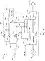
- FIG. 1 shows a high-level schematic illustration of a fuel purge system 100 for a combustion turbine engine 105 according to one embodiment of the present invention.
- a combustion turbine engine can include all types of combustion turbine or rotary engines, including engines of power generating plants (e.g., a gas turbine engine) and others, as well as aircraft engines.
- Combustion turbine engine 105 includes an electric generator 110 that is connected by a rotor shaft 115 to a compressor 120 and a turbine 125. The connections and configuration of these components may be made pursuant to conventional technology.
- a combustor 130 may be positioned between compressor 120 and turbine 125.
- an air intake line 135 may be connected to compressor 120.
- Air intake line 135 provides inlet air to compressor 120.
- a first conduit 143 may connect compressor 120 to combustor 130 and may direct the air that is compressed by compressor 120 into combustor 130.
- Combustor 130 generally combusts the supply of compressed air with a fuel provided from fuel gas supply 140 in a known manner to produce a hot compressed motive gas, also known as a working fluid.
- a second conduit 145 conducts the working fluid away from combustor 130 and directs it to turbine 125, where it is used to drive turbine 125.
- the working fluid expands in turbine 125, causing rotor blades of turbine 125 to rotate about rotor shaft 115.
- the rotation of the blades causes rotor shaft 115 to rotate.
- the mechanical energy associated with the rotating rotor shaft 115 may be used to drive rotor blades of compressor 120 to rotate about rotor shaft 115.
- the rotation of the rotor blades of compressor 120 causes it to supply the compressed air to combustor 130 for combustion. This in turn causes coils of generator 110 to generate electric power and produce electricity.
- combustion turbine engine 105 as shown in FIG. 1 and described above, is only one example of a turbine engine that can be implemented with the fuel purge system of the present invention according to various embodiments described herein.
- Combustion turbine engine 105 is not meant to limit the scope of the various embodiments of the fuel purge system described herein.
- Other combustion turbine engine applications are suitable for use with the various embodiments of the fuel purge system described herein.
- Fuel purge system 100 may be implemented with the fuel gas delivery system of combustion turbine engine 105.
- the fuel gas delivery system can receive fuel gas from fuel gas supply 140 via a fuel gas supply line 150.
- fuel gas from fuel gas supply line 150 can be delivered to fuel line 155 and fuel line 160, which feed fuel gas into combustor 130 for combustion with compressed air provided by compressor 120.
- a gas control valve 165 can control the flow of fuel gas provided from fuel gas supply 140 through fuel line 155 to combustor 130
- a gas control valve 170 can control the flow of fuel gas provided from fuel gas supply 140 through fuel line 160 to combustor 130.
- fuel line 155 and fuel line 160 can have other components that facilitate the supply of fuel gas to combustor 130.
- portions of fuel line 155 and fuel line 160 that are upstream (i.e., to the left) of gas control valve 165 and gas control valve 170, respectively, may include components such as, for example, fuel compressors, fuel after-coolers, straining elements, instrumentation that monitors pressure and temperature, stop valves, stop/speed ratio valves, vent valves, and the like.
- portions of fuel line 155 and fuel line 160 that are downstream (i.e., to the right) of gas control valve 165 and gas control valve 170, respectively, may include components, such as, for example, fuel passage manifolds and accompanying fuel nozzles, straining elements, pressure gages, conduits, and the like. As used herein, these components of fuel line 155 and fuel line 160 that are downstream of gas control valve 165 and gas control valve 170, form fuel gas circuits which are used to deliver fuel gas to combustor 130.
- the delivery of fuel gas to combustor 130 from the different fuel gas circuits is staged as the load of combustion turbine engine 105 is ramped up.
- some of the fuel gas circuits will have no fuel scheduled.
- the fuel gas circuits When the fuel gas circuits have no fuel scheduled they are defueled becoming dormant during that particular combustion mode. While the fuel gas circuits are dormant, it is necessary to purge these stagnant passages in order to prevent condensate from accumulating, and to minimize the potential for auto-ignition.
- fuel gas from fuel gas supply 140 can be used to purge gas from dormant fuel gas circuits.
- fuel purge system 100 of FIG. 1 can include a gas purge valve 175 to purge fuel line 155 with fuel gas from fuel gas supply 140.
- a fuel gas purge line 180 branching off fuel line 155 supplies a predetermined amount of fuel gas, via gas purge valve 175 and a fuel gas orifice 185, while fuel line 155 is dormant (i.e., gas control valve 165 is off). This will maintain a positive pressure in fuel line 155.
- fuel gas orifice 185 is optional and that the effect provided by orifice 185 can be obtained by sizing gas purge valve 175 to obtain the desired flow restriction to facilitate the gas purge with the desired amount of fuel gas necessary to purge the line.
- FIG. 1 shows that an air purge valve 187 can be used to facilitate the purge of fuel line 160 while dormant.
- air purge valve 187 can be opened while fuel line 160 is dormant (i.e., gas control valve 170 is off), to provide the purge air to the fuel line 160 in order to maintain a positive pressure in the line.
- a controller 192 can control the fuel gas delivery of fuel gas from fuel gas supply 140 to combustor 130, as well as the purging of fuel lines 155 and 160 with fuel gas and purge air, respectively.
- the settings of gas control valve 165 and gas control valve 170 that regulate the flow of fuel gas through fuel line 155 and fuel line 160, respectively may be controlled pursuant to control signals generated from controller 192 along respective control lines 193 and 195 indicated in FIG. 1 as dashed lines.
- the settings of gas purge valve 175 and air purge valve 187 that purge fuel gas through fuel line 155 and purge air through fuel line 160, respectively may be controlled pursuant to control signals generated from controller 192 along respective control lines 196 and 197 indicated in FIG. 1 as dashed lines.
- Controller 192 may comprise an electronic or computer implemented device that includes control logic pertaining to the operation of the one or more valves. Pursuant to this control logic and/or one or more operating parameters monitored by controller 192, the controller can send electronic signals to the one or more valves and, thereby, control the settings of the valves. In this manner, the one or more valves may be controlled, for example, to perform functions such as controlling the flow of fuel gas through fuel lines 155 and 160, and controlling the purge of these lines, while dormant with fuel gas and purge air.
- controller 192 may be implemented in the form of an entirely hardware embodiment or an embodiment containing both hardware and software elements.
- a single special-purpose integrated circuit such as an application specific integrated circuit (ASIC)
- ASIC application specific integrated circuit
- Controller 192 may also be implemented using a suitably programmed general-purpose computer, such as a microprocessor or microcontroller, or other process device such as a central processing unit (CPU) or microprocessor unit (MPU), either alone or in conjunction with one or more peripheral data and signal processing devices.
- CPU central processing unit
- MPU microprocessor unit
- Controller 192 may also be implemented using a variety of separate dedicated or programmable integrated or other electronic circuits or devices, such as hardwired electronic or logic circuits, including discrete element circuits or programmable logic devices such as programmable logic devices (PLDs), programmable array logic devices (PALs), programmable logic arrays (PLAs), or the like.
- PLDs programmable logic devices
- PALs programmable array logic devices
- PLAs programmable logic arrays
- controller 192 may be implemented in software, which includes but is not limited to firmware, resident software, microcode, etc.
- the processing functions performed by controller 192 can take the form of a computer program product accessible from a computer-usable or computer-readable medium providing program code for use by or in connection with a computer or any instruction execution system (e.g., processing units).
- a computer-usable or computer readable medium can be any computer readable storage medium that can contain or store the program for use by or in connection with the computer or instruction execution system.
- the computer readable medium can be an electronic, magnetic, optical, electromagnetic, infrared, or semiconductor system (or apparatus or device).
- Examples of a computer-readable medium include a semiconductor or solid state memory, a random access memory (RAM), a read-only memory (ROM), a rigid magnetic disk and an optical disk.
- Current examples of optical disks include a compact disk - read only memory (CD-ROM), a compact disk - read/write (CD-R/W) and a digital video disc (DVD).
- combustion turbine engine 105 and fuel purge system 100 may have other components in addition to those shown in FIG. 1 .
- those other components may include filters, fuel gas scrubbers, heaters, sensors, etc.
- filters, fuel gas scrubbers, heaters, sensors, etc. The inclusion and configuration of these elements are not essential to the operation of the various embodiments of the present invention described herein.
- these other components are neither shown in FIG. 1 nor discussed in detail in this disclosure.
- the fuel purge system shown in FIGS. 2-5 may include other components in addition to those shown. However, due to their tangential nature with regard to the various embodiments of the present invention, these components are neither illustrated nor described herein.
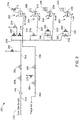
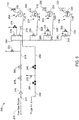
- FIGS. 2-5 show a fuel purge system 200 operating in various combustion modes that can be implemented with a combustion turbine engine such as the one illustrated in FIG. 1 , or in a different combustion turbine engine application. All of the components of fuel purge system 200 that are illustrated in FIGS. 2-5 are substantially the same. Accordingly, for the sake of clarity and brevity, similar numerical identifiers are used in FIGS. 2-5 for common components. Because each of the illustrations shown in FIGS. 2-5 represent a different mode of operation for the combustion turbine engine, the components such as the various valves may operate in a different manner from one figure to the next. In order to illustrate these operational differences between combustion modes, shading of the valves is used to represent different operational positions. As used herein, valves that are shaded are an indication that the valves are in a closed position, while valves that are not shaded are an indication that the valves are in an open position.
- Fuel purge system 200 is shown in use with four fuel gas circuits 202, 204, 206 and 208, in which each can deliver fuel gas from a fuel gas supply 210 to a combustor (not shown).
- Fuel gas circuit 202 may include a fuel passage manifold (D5) 212 with accompanying fuel nozzles 214 that direct the flow of any fuel gas supplied along fuel line 216 to the combustor.
- fuel nozzles 214 of D5 manifold 212 may have five nozzles to direct the flow of fuel gas supplied along fuel line 216 to the combustor.
- Fuel gas circuit 204 may include a fuel passage manifold (PM1) 218 with accompanying fuel nozzles 220 that direct the flow of any fuel gas supplied along fuel line 222 to the combustor.
- fuel nozzles 220 of PM1 manifold 218 may have one nozzle to direct the flow of fuel gas supplied along fuel line 222 to the combustor.
- Fuel gas circuit 206 may include a fuel passage manifold (PM3) 224 with accompanying fuel nozzles 226 that direct the flow of any fuel gas supplied along fuel line 228 to the combustor.
- fuel nozzles 226 of PM3 manifold 224 may have three nozzles to direct the flow of fuel gas supplied along fuel line 228 to the combustor.
- Fuel gas circuit 208 may include a fuel passage manifold (PM2) 230 with accompanying fuel nozzles 232 that direct the flow of any fuel gas supplied along fuel line 234 to the combustor.
- fuel nozzles 232 of PM2 manifold 230 may have two nozzles to direct the flow of fuel gas supplied along fuel line 234 to the combustor.
- fuel nozzles 214, 220, 226 and 232 associated with D5 manifold 212, PM1 manifold 218, PM3 manifold 224 and PM2 manifold 230, respectively, can each be coupled to a combustion can.
- each of the combustion cans may be arranged in an annular array to form the combustor. Combustion in such an arrangement is generally initiated within the combustion cans at a point slightly downstream of each the nozzles emanating from the manifolds, where air from the compressor is mixed with fuel from the nozzles for combustion thereof.
- Gas control valves 236, 238, 240 and 242 can be used to control the flow of fuel gas provided from fuel gas supply 210 to fuel gas circuits 202, 204, 206 and 208, respectively.
- gas control valve 236 is the D5 gas control valve for D5 manifold 212
- gas control valve 238 is the PM1 gas control valve for PM1 manifold 218,
- gas control valve 240 is the PM3 gas control valve for PM3 manifold 224
- gas control valve 242 is the PM2 gas control valve for PM2 manifold 230.
- a fuel gas supply line 244 can be used to deliver fuel gas from fuel gas supply 210 to fuel gas circuits 202, 204, 206 and 208 via gas control valves 236, 238, 240 and 242, respectively.
- a straining element 246 e.g., a Y-strainer
- a stop valve 248 can be positioned along fuel gas supply line 244, downstream of straining element 246, to be used in scenarios (e.g., fail-safe tripping operations), where it is desirable to stop the flow of fuel gas from fuel gas supply 210 to fuel gas circuits 202, 204, 206 and 208.
- stop valve 248 can act as a backup stop valve for a stop/speed ratio valve 250 located downstream of stop valve 248.
- stop/speed ratio valve 250 can operate as the primary stop valve making it an integral part of protecting the combustion turbine engine.
- Stop/speed ratio valve 250 can also be used to regulate the pressure in fuel gas supply line 244 upstream of gas control valves 236, 238, 240 and 242.
- a vent valve 252 can be located downstream of stop/speed ratio valve 250 in order to further complement the protective features of stop valve 248 and stop/speed ratio valve 250 during a fail-safe operation scenario.
- vent valve 252 can be opened upon the closure of stop valve 248 and stop/speed ratio valve 250 to bleed any fuel gas that remains in fuel gas supply line 244. This prevents the fuel gas from flowing further through a distribution header 254, and onto fuel gas circuits 202, 204, 206 and 208 via their respective gas control valves 236, 238, 240 and 242.
- fuel purge system 200 can be used to selectively purge fuel gas circuits 202, 204, 206 and 208 with fuel gas while the fuel gas circuits are defueled into a dormant state.
- a by-pass valve 256 and a fuel gas orifice 258 can be coupled about gas control valve 240.
- gas control valve 240 In this manner, when fuel gas circuit 206 is dormant (i.e., gas control valve 240 is closed), a predetermined amount of fuel gas can be supplied from distribution header 254 to fuel gas orifice 258 and by-pass valve 256.
- a by-pass valve 260 and a fuel gas orifice 262 can also be coupled about gas control valve 242.
- a predetermined amount of fuel gas can be supplied from distribution header 254 to fuel gas orifice 262 and by-pass valve 260.
- a positive pressure can also prevent overheating at fuel nozzles 232 of the PM2 manifold 230.
- fuel gas orifices 258 and 262 can be used as an option.
- the effect provided by fuel gas orifices 258 and 262 with fuel purge system 200 can be obtained by sizing by-pass valves 256 and 260 in an appropriate manner to obtain the desired flow restriction with the desired amount of fuel gas to purge fuel gas circuits 206 and 208.
- some fuel gas circuits may not be able to be purged with fuel gas, and thus these circuits can be purged with purge air obtained from the compressor (not shown in these figures).
- fuel gas circuit 202 which includes the D5 gas manifold 212, fuel nozzles 214 and fuel line 216, with fuel gas at high load operations because it can increase emissions released from the turbine (not shown in these figures).
- purge air can be supplied to fuel gas circuit 202 via a double-block and bleed configuration formed from isolation valves 264 and 266, which can be stop valves.
- isolation valves 264 and 266 can be positioned along an air purge line 268 that supplies purge air from the compressor to fuel gas circuit 202.
- a vent valve 270 can be positioned between isolation valves 264 and 266, and be used to bleed any purge air from air purge line 268 that remains in the line when the isolation valves 264 and 266 have been closed.
- fuel purge system 200 can include an isolation valve 272, which can be a stop valve, coupled in series, downstream of control valve 236.
- a vent valve 274 can be coupled between isolation valve 272 and gas control valve 236. In this manner, isolation valve 272 and vent valve 274 can prevent fuel gas from mixing with the purge air.
- gas control valve 236 is in a closed position, isolation valve 272 can then be closed to ensure that fuel gas does not mix with the purge air while air purge line 268 supplies the purge air to the dormant fuel gas circuit 202.
- vent valve 274 can be opened to bleed off any remaining fuel gas that lies in the line between gas control valve 236 and isolation valve 272.
- gas control valve 236, isolation valve 272, and vent valve 274 collectively form a double-block and bleed valve configuration that can prevent a combustible condition from arising.
- FIGS. 2-5 represent different combustion modes of operation for one example of a combustion turbine engine.
- the combustion turbine engine is of the type that generates low-levels of NOx emissions. Consequently, the delivery of fuel gas to the combustor from the different fuel gas circuits (e.g., 202, 204, 206 and 208) is staged as the load of the combustion turbine engine is ramped up.
- a combustion turbine engine of the type that generates low-levels of NOx is configured to have several different combustion modes of operation that can be implemented during transient-state (e.g., pre-start, start-up, and shut-down) and steady-state (e.g., loading) operations of the engine.
- combustion modes of operation are indicative of only a few example of combustion modes, and the operation of fuel purge system 200 during these other modes will depend on the particular stage of the engine and the desired levels of NOx emissions.
- fuel purge system 200 is shown operating during a full premix operation.
- fuel gas circuits 204, 206 and 208 are fueled, while fuel gas circuit 202 is defueled into a dormant state.
- fuel nozzles 220, 226 and 232 all can receive fuel gas from fuel gas supply 210.
- Fuel nozzles 220, 226 and 232 can receive fuel gas because each of their respective gas control valves (i.e., 238, 240 and 242) are open (non-shaded valves indicate valves are in an open position), thereby permitting the flow of fuel gas from distribution header 254 to PM1 manifold 218, PM3 manifold 224, and PM2 manifold 230 and their respective nozzles. While fuel gas circuits 204, 206 and 208 are being fueled, fuel gas circuit 202 can be purged because it is dormant. To purge fuel gas circuit 202, gas control valve 236 and isolation valve 272 are closed (shaded valves indicate valves are in a closed position), while vent valve 274 is open.
- gas control valve 236 and isolation valve 272 are closed (shaded valves indicate valves are in a closed position), while vent valve 274 is open.
- Closing gas control valve 236 and isolation valve 272 stops the flow of fuel gas from distribution header 254 to D5 manifold 212 and accompanying fuel nozzles 214. Opening vent valve 274 can permit the bleeding of any fuel gas that remains between gas control valve 236 and isolation valve 272. Keeping gas control valve 236 and isolation valve 272 closed and vent valve 274 open, prevents mixing of any fuel in fuel line 216 while purge air is supplied from the compressor.
- purge air from the compressor is supplied along air purge line 268 when isolation valves 264 and 266 are open (non-shaded valves indicate valves are in an open position) and vent valve 270 is closed (shaded valve indicate a valve in a closed position). Preventing mixing of any fuel in fuel line 216 while purge air is being supplied is beneficial in that potential auto-ignition events are prevented.
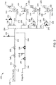
- fuel purge system 200 is shown operating during a partial premix operation with diffusion.
- fuel gas circuits 202 and 204 are fueled, while fuel gas circuits 206 and 208 are dormant.
- fuel nozzles 214 and 220 can receive fuel gas from fuel gas supply 210.
- Fuel nozzles 214 and 220 can receive fuel gas because each of their respective gas control valves (i.e., 236 and 238) are open (non-shaded valves indicate valves are in an open position), thereby permitting the flow of fuel gas from distribution header 254 to D5 manifold 212 and PM1 manifold 218, and their respective nozzles.
- isolation valve 272 is also open (non-shaded valve indicates valve is in an open position), while vent valve 274 is closed (non-shaded valve indicate valve is open position) in order to supply fuel gas to fuel gas circuit 202.
- fuel gas circuits 202 and 204 While fuel gas circuits 202 and 204 are being fueled, fuel gas circuits 206 and 208 can be purged because they are dormant.
- their respective gas control valves 240 and 242 are closed (shaded valves indicate valves are in a closed position).
- bypass valve 256 and bypass valve 260 are open (non-shaded valves indicate valves are in an open position).
- purge air from the compressor is not supplied along air purge line 268.
- isolation valves 264 and 266 are closed (shaded valves indicate valves are in a closed position), and vent valve 270 is open (non-shaded valve indicates a valve in an open position).
- fuel gas circuits 206 and 208 are purged with a predetermined amount of fuel gas, while fuel gas circuits 202 and 204 are fueled. Purging fuel gas circuits 206 and 208 with fuel gas maintains a positive pressure, which prevents backflow. In addition, purging fuel gas circuits 206 and 208 in this manner prevents overheating at fuel nozzles 226 and 232.
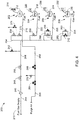
- fuel purge system 200 is shown operating during another example of a partial premix operation with diffusion.
- fuel gas circuits 202, 204 and 206 are fueled, while fuel gas circuit 208 is dormant.
- fuel nozzles 214, 220 and 226 can receive fuel gas from fuel gas supply 210.
- Fuel nozzles 214, 220 and 226 can receive fuel gas because each of their respective gas control valves (i.e., 236, 238 and 240) are open (non-shaded valves indicate valves are in an open position), thereby permitting the flow of fuel gas from distribution header 254 to D5 manifold 212, PM1 manifold 218, and PM3 manifold 206, and their respective nozzles.
- isolation valve 272 is also open (non-shaded valve indicates valve is in an open position), and vent valve 274 is closed (shaded valve indicates valve is in closed position) for fuel gas circuit 202.
- by-pass valve 256 is closed (shaded valve indicates valve is in a closed position) in addition to having gas control valve 240 open.
- fuel gas circuit 208 can be purged while it is dormant.
- its respective gas control valve 242 is closed (shaded valve indicate valve is in a closed position).
- bypass valve 260 is open (non-shaded valve indicate valve is in an open position).
- purge air from the compressor is not supplied along air purge line 268.
- isolation valves 264 and 266 are closed (shaded valves indicate valves are in a closed position), and vent valve 270 is open (non-shaded valve indicates a valve in an open position).
- fuel gas circuit 208 is purged with a predetermined amount of fuel gas, while fuel gas circuits 202, 204 and 206 are fueled. Purging fuel gas circuit 208 with fuel gas maintains a positive pressure, which prevent backflow. In addition, purging fuel gas circuit 208 in this manner prevents overheating at fuel nozzles 232.
- fuel purge system 200 is shown operating during a full premix operation with diffusion.
- all fuel gas circuits 202, 204, 206 and 208 are fueled and none are dormant.
- fuel nozzles 214, 220, 226 and 232 all can receive fuel gas from fuel gas supply 210.
- Fuel nozzles 214, 220, 226 and 232 can receive fuel gas because each of their respective gas control valves (i.e., 236, 238, 240 and 242) are open (non-shaded valves indicate valves are in an open position), thereby permitting the flow of fuel gas from distribution header 254 to D5 manifold 212, PM1 manifold 218, PM3 manifold 224 and PM2 manifold 230, and their respective nozzles.
- gas control valves i.e., 236, 238, 240 and 242
- by-pass valve 256 and by-pass valve 260 are closed (shaded valves indicate valves are in a closed position). This ensures that fuel gas is supplied to fuel gas circuits 206 and 208 via fuel lines 228 and 234, respectively. Also, in this example, because fuel gas circuit 202 is not purge with purge air, the compressor does not supply any purge air to this circuit. Thus, isolation valves 264 and 266 are closed (shaded valves indicate valves are in a closed position), and vent valve 270 is open (non-shaded valve indicates a valve in an open position) to prevent the flow of purge air into fuel gas circuit 202.
- isolation valve 272 is open (non-shaded valve indicates valve is in an open position), and vent valve 274 is closed (non-shaded valve indicate valve is open position) while gas control valve 236 is open.
Landscapes
- Engineering & Computer Science (AREA)
- Chemical & Material Sciences (AREA)
- Combustion & Propulsion (AREA)
- Mechanical Engineering (AREA)
- General Engineering & Computer Science (AREA)
- Feeding And Controlling Fuel (AREA)
- Supplying Secondary Fuel Or The Like To Fuel, Air Or Fuel-Air Mixtures (AREA)
- Output Control And Ontrol Of Special Type Engine (AREA)
- Fuel Cell (AREA)
Applications Claiming Priority (1)
| Application Number | Priority Date | Filing Date | Title |
|---|---|---|---|
| US13/484,410 US9103284B2 (en) | 2012-05-31 | 2012-05-31 | Utilization of fuel gas for purging a dormant fuel gas circuit |
Publications (3)
| Publication Number | Publication Date |
|---|---|
| EP2669493A2 EP2669493A2 (en) | 2013-12-04 |
| EP2669493A3 EP2669493A3 (en) | 2018-04-04 |
| EP2669493B1 true EP2669493B1 (en) | 2020-04-08 |
Family
ID=48484994
Family Applications (1)
| Application Number | Title | Priority Date | Filing Date |
|---|---|---|---|
| EP13168446.6A Active EP2669493B1 (en) | 2012-05-31 | 2013-05-20 | Utilization of fuel gas for purging a dormant fuel gas circuit |
Country Status (5)
| Country | Link |
|---|---|
| US (1) | US9103284B2 (enExample) |
| EP (1) | EP2669493B1 (enExample) |
| JP (1) | JP6506496B2 (enExample) |
| CN (1) | CN103590906B (enExample) |
| RU (1) | RU2013125141A (enExample) |
Families Citing this family (25)
| Publication number | Priority date | Publication date | Assignee | Title |
|---|---|---|---|---|
| US10012148B2 (en) * | 2014-05-23 | 2018-07-03 | General Electric Company | Method of purging a combustor |
| JP2016048044A (ja) * | 2014-08-27 | 2016-04-07 | 川崎重工業株式会社 | ガスタービンエンジンシステム |
| US10012387B2 (en) | 2014-12-05 | 2018-07-03 | General Electric Company | Fuel supply system for a gas turbine engine |
| FR3030628B1 (fr) * | 2014-12-23 | 2017-02-03 | Ge Energy Products France Snc | Installation et procede d'alimentation d'une chambre de combustion, notamment d'une turbine a gaz, a injection d'eau dans une cavite d'un circuit de purge |
| JP6520274B2 (ja) * | 2015-03-23 | 2019-05-29 | 三浦工業株式会社 | ボイラ装置 |
| CN104879221A (zh) * | 2015-05-19 | 2015-09-02 | 大连派思燃气系统股份有限公司 | 用于燃气吹扫管线上的双重阻断与排放工艺系统 |
| JP6651389B2 (ja) * | 2016-03-08 | 2020-02-19 | 三菱日立パワーシステムズ株式会社 | 燃料制御装置、燃焼器、ガスタービン、燃料制御方法及びプログラム |
| US10384791B2 (en) | 2016-07-21 | 2019-08-20 | United Technologies Corporation | Cross engine coordination during gas turbine engine motoring |
| EP3273006B1 (en) | 2016-07-21 | 2019-07-03 | United Technologies Corporation | Alternating starter use during multi-engine motoring |
| US10618666B2 (en) | 2016-07-21 | 2020-04-14 | United Technologies Corporation | Pre-start motoring synchronization for multiple engines |
| US10221774B2 (en) | 2016-07-21 | 2019-03-05 | United Technologies Corporation | Speed control during motoring of a gas turbine engine |
| EP3273016B1 (en) | 2016-07-21 | 2020-04-01 | United Technologies Corporation | Multi-engine coordination during gas turbine engine motoring |
| US10787968B2 (en) | 2016-09-30 | 2020-09-29 | Raytheon Technologies Corporation | Gas turbine engine motoring with starter air valve manual override |
| US10408132B2 (en) * | 2016-11-17 | 2019-09-10 | General Electric Company | Systems and methods for adaptively purging fuel circuits |
| US10823079B2 (en) * | 2016-11-29 | 2020-11-03 | Raytheon Technologies Corporation | Metered orifice for motoring of a gas turbine engine |
| US20190226592A1 (en) * | 2018-01-25 | 2019-07-25 | Honeywell International Inc. | Double block and bleed valve with flex bypass for effective and efficient system isolation |
| US11486303B2 (en) * | 2019-05-15 | 2022-11-01 | Pratt & Whitney Canada Corp. | System and method for purging a fuel manifold of a gas turbine engine using a pump |
| US11713723B2 (en) | 2019-05-15 | 2023-08-01 | Pratt & Whitney Canada Corp. | Method and system for operating an engine |
| US11680549B2 (en) * | 2019-10-04 | 2023-06-20 | Hamilton Sundstrand Corporation | Fluid injection systems for fluid line purging |
| US11760500B2 (en) | 2019-11-11 | 2023-09-19 | Pratt & Whitney Canada Corp. | Systems and methods for filling a fuel manifold of a gas turbine engine |
| CN113513409B (zh) * | 2021-08-20 | 2022-12-20 | 中国联合重型燃气轮机技术有限公司 | 用于燃气轮机的吹扫系统及其控制方法 |
| CN113931754B (zh) * | 2021-10-18 | 2023-02-07 | 烟台杰瑞石油装备技术有限公司 | 气体燃料供应系统 |
| US11542870B1 (en) | 2021-11-24 | 2023-01-03 | General Electric Company | Gas supply system |
| CA3245957A1 (en) * | 2022-03-24 | 2023-09-28 | Nuovo Pignone Tecnologie - S.R.L. | IGNITION APPARATUS AND METHOD FOR IGNITION OF HIGH-REACTION COMBUSTION GASES |
| CN114992517A (zh) * | 2022-06-22 | 2022-09-02 | 华电通用轻型燃机设备有限公司 | 航改型燃气轮机天然气进气及补燃系统 |
Family Cites Families (23)
| Publication number | Priority date | Publication date | Assignee | Title |
|---|---|---|---|---|
| US3875380A (en) * | 1971-12-06 | 1975-04-01 | Westinghouse Electric Corp | Industrial gas turbine power plant control system and method implementing improved dual fuel scheduling algorithm permitting automatic fuel transfer under load |
| JPS5914614B2 (ja) * | 1978-06-05 | 1984-04-05 | 株式会社日立製作所 | ガスタ−ビン用圧力噴霧式二燃料焚きノズルのパ−ジ方法及び装置 |
| JPS5855332B2 (ja) * | 1978-06-07 | 1983-12-09 | 株式会社日立製作所 | 二燃料焚き圧力噴霧式燃料ノズルのパ−ジ方法及び装置 |
| DE4335412B4 (de) * | 1993-10-18 | 2005-01-27 | Alstom | Verfahren und Vorrichtung zur Brennstoffverteilung für Ringbrennkammern von Gasturbinenanlagen |
| US6145294A (en) | 1998-04-09 | 2000-11-14 | General Electric Co. | Liquid fuel and water injection purge system for a gas turbine |
| EP0976982B1 (de) * | 1998-07-27 | 2003-12-03 | ALSTOM (Switzerland) Ltd | Verfahren zum Betrieb einer Gasturbinenbrennkammer mit gasförmigem Brennstoff |
| US6598383B1 (en) * | 1999-12-08 | 2003-07-29 | General Electric Co. | Fuel system configuration and method for staging fuel for gas turbines utilizing both gaseous and liquid fuels |
| JP4335397B2 (ja) * | 2000-02-01 | 2009-09-30 | 三菱重工業株式会社 | ガスタービン燃料ガス漲装置 |
| US6405524B1 (en) | 2000-08-16 | 2002-06-18 | General Electric Company | Apparatus for decreasing gas turbine combustor emissions |
| US6438963B1 (en) | 2000-08-31 | 2002-08-27 | General Electric Company | Liquid fuel and water injection purge systems and method for a gas turbine having a three-way purge valve |
| JP4118554B2 (ja) * | 2000-12-21 | 2008-07-16 | 株式会社東芝 | ガスタービン燃焼器システム |
| GB0206220D0 (en) * | 2002-03-15 | 2002-05-01 | Lucas Industries Ltd | Fuel system |
| JP4206908B2 (ja) * | 2003-11-14 | 2009-01-14 | 株式会社日立製作所 | ガスタービン燃焼器 |
| US7104070B2 (en) | 2004-03-04 | 2006-09-12 | General Electric Company | Liquid fuel nozzle apparatus with passive water injection purge |
| JP4119908B2 (ja) * | 2005-09-14 | 2008-07-16 | 三菱重工業株式会社 | ガスタービンの燃焼制御装置 |
| US7721521B2 (en) | 2005-11-07 | 2010-05-25 | General Electric Company | Methods and apparatus for a combustion turbine fuel recirculation system and nitrogen purge system |
| JP4865476B2 (ja) * | 2006-09-28 | 2012-02-01 | 三菱重工業株式会社 | ガスタービンの起動停止方法及び起動停止制御装置 |
| US7770400B2 (en) * | 2006-12-26 | 2010-08-10 | General Electric Company | Non-linear fuel transfers for gas turbines |
| US20090025396A1 (en) * | 2007-07-24 | 2009-01-29 | General Electric Company | Parallel turbine fuel control valves |
| JP4959523B2 (ja) * | 2007-11-29 | 2012-06-27 | 株式会社日立製作所 | 燃焼装置,燃焼装置の改造方法及び燃焼装置の燃料噴射方法 |
| US20110167782A1 (en) * | 2010-01-13 | 2011-07-14 | Scott Arthur Tetzlaff | Systems and apparatus for a fuel control assembly for use in a gas turbine engine |
| US20110265488A1 (en) * | 2010-04-29 | 2011-11-03 | General Electric Company | ALTERNATE METHOD FOR DILUENT INJECTION FOR GAS TURBINE NOx EMISSIONS CONTROL |
| CN201902264U (zh) * | 2010-12-24 | 2011-07-20 | 沈阳黎明航空发动机(集团)有限责任公司 | 一种重型燃机燃料调节系统 |
-
2012
- 2012-05-31 US US13/484,410 patent/US9103284B2/en not_active Expired - Fee Related
-
2013
- 2013-05-20 EP EP13168446.6A patent/EP2669493B1/en active Active
- 2013-05-30 RU RU2013125141/06A patent/RU2013125141A/ru not_active Application Discontinuation
- 2013-05-30 JP JP2013113570A patent/JP6506496B2/ja not_active Expired - Fee Related
- 2013-05-31 CN CN201310210204.3A patent/CN103590906B/zh not_active Expired - Fee Related
Non-Patent Citations (1)
| Title |
|---|
| None * |
Also Published As
| Publication number | Publication date |
|---|---|
| CN103590906A (zh) | 2014-02-19 |
| JP6506496B2 (ja) | 2019-04-24 |
| CN103590906B (zh) | 2017-05-17 |
| JP2013249839A (ja) | 2013-12-12 |
| US20130318993A1 (en) | 2013-12-05 |
| EP2669493A2 (en) | 2013-12-04 |
| RU2013125141A (ru) | 2014-12-10 |
| EP2669493A3 (en) | 2018-04-04 |
| US9103284B2 (en) | 2015-08-11 |
Similar Documents
| Publication | Publication Date | Title |
|---|---|---|
| EP2669493B1 (en) | Utilization of fuel gas for purging a dormant fuel gas circuit | |
| US11549687B2 (en) | Combustion staging system | |
| EP2843211B1 (en) | Gas turbine with improved part load emissions behaviour and method thereof | |
| US6405524B1 (en) | Apparatus for decreasing gas turbine combustor emissions | |
| JP2015045331A (ja) | ガスタービンエンジンの燃焼室における燃料の分布を制御するためのシステムおよび方法 | |
| US11053861B2 (en) | Overspeed protection system and method | |
| JP2009052548A (ja) | ガスタービンエミッション規制順守を拡大適用するためのシステム及び方法 | |
| JP2017015074A (ja) | 発電システム排気冷却 | |
| JP2017106444A (ja) | 入口抽気加熱制御システム | |
| JP2017015082A (ja) | 発電システム排気冷却 | |
| JP5972810B2 (ja) | ガスタービンシステム、ガスタービンの燃焼器制御装置、及びガスタービンの燃焼器制御方法 | |
| JP2018112388A (ja) | オートサーマル燃料ノズルの流れ調整 | |
| JP6827775B2 (ja) | ガスタービンエンジンで使用するための燃料供給システム | |
| EP2896793B1 (en) | Method of operating a gas turbine assembly and the gas turbine assembly | |
| US9353691B2 (en) | Fuel routing system of a gas turbine engine and method of routing fuel | |
| JP5147938B2 (ja) | バーナおよびバーナの運転方法 | |
| JP2017106324A (ja) | 燃焼制御システム、ガスタービン、燃焼制御方法及びプログラム | |
| AU2016217888B2 (en) | Operation method for improving partial load efficiency in a gas turbine and gas turbine with improved partial load efficiency | |
| US20250129748A1 (en) | Turbine engine including a fuel and steam system | |
| US11781479B2 (en) | Turbofan gas turbine engine with combusted compressor bleed flow | |
| Price et al. | Enhancements to the load acceptance and rejection capability of a high pressure aeroderivative engine | |
| CN114673591A (zh) | 运行燃气涡轮发电设备的方法和燃气涡轮发电设备 | |
| JP2016050580A (ja) | 複合サイクル発電プラントの熱エネルギー節減方法 |
Legal Events
| Date | Code | Title | Description |
|---|---|---|---|
| PUAI | Public reference made under article 153(3) epc to a published international application that has entered the european phase |
Free format text: ORIGINAL CODE: 0009012 |
|
| AK | Designated contracting states |
Kind code of ref document: A2 Designated state(s): AL AT BE BG CH CY CZ DE DK EE ES FI FR GB GR HR HU IE IS IT LI LT LU LV MC MK MT NL NO PL PT RO RS SE SI SK SM TR |
|
| AX | Request for extension of the european patent |
Extension state: BA ME |
|
| PUAL | Search report despatched |
Free format text: ORIGINAL CODE: 0009013 |
|
| AK | Designated contracting states |
Kind code of ref document: A3 Designated state(s): AL AT BE BG CH CY CZ DE DK EE ES FI FR GB GR HR HU IE IS IT LI LT LU LV MC MK MT NL NO PL PT RO RS SE SI SK SM TR |
|
| AX | Request for extension of the european patent |
Extension state: BA ME |
|
| RIC1 | Information provided on ipc code assigned before grant |
Ipc: F02C 7/22 20060101AFI20180223BHEP Ipc: F02C 9/34 20060101ALI20180223BHEP |
|
| STAA | Information on the status of an ep patent application or granted ep patent |
Free format text: STATUS: REQUEST FOR EXAMINATION WAS MADE |
|
| 17P | Request for examination filed |
Effective date: 20181004 |
|
| RBV | Designated contracting states (corrected) |
Designated state(s): AL AT BE BG CH CY CZ DE DK EE ES FI FR GB GR HR HU IE IS IT LI LT LU LV MC MK MT NL NO PL PT RO RS SE SI SK SM TR |
|
| STAA | Information on the status of an ep patent application or granted ep patent |
Free format text: STATUS: EXAMINATION IS IN PROGRESS |
|
| 17Q | First examination report despatched |
Effective date: 20190403 |
|
| GRAP | Despatch of communication of intention to grant a patent |
Free format text: ORIGINAL CODE: EPIDOSNIGR1 |
|
| STAA | Information on the status of an ep patent application or granted ep patent |
Free format text: STATUS: GRANT OF PATENT IS INTENDED |
|
| INTG | Intention to grant announced |
Effective date: 20191029 |
|
| GRAS | Grant fee paid |
Free format text: ORIGINAL CODE: EPIDOSNIGR3 |
|
| GRAA | (expected) grant |
Free format text: ORIGINAL CODE: 0009210 |
|
| STAA | Information on the status of an ep patent application or granted ep patent |
Free format text: STATUS: THE PATENT HAS BEEN GRANTED |
|
| AK | Designated contracting states |
Kind code of ref document: B1 Designated state(s): AL AT BE BG CH CY CZ DE DK EE ES FI FR GB GR HR HU IE IS IT LI LT LU LV MC MK MT NL NO PL PT RO RS SE SI SK SM TR |
|
| REG | Reference to a national code |
Ref country code: CH Ref legal event code: EP Ref country code: AT Ref legal event code: REF Ref document number: 1254691 Country of ref document: AT Kind code of ref document: T Effective date: 20200415 |
|
| REG | Reference to a national code |
Ref country code: DE Ref legal event code: R096 Ref document number: 602013067612 Country of ref document: DE |
|
| REG | Reference to a national code |
Ref country code: IE Ref legal event code: FG4D |
|
| REG | Reference to a national code |
Ref country code: NL Ref legal event code: MP Effective date: 20200408 |
|
| REG | Reference to a national code |
Ref country code: LT Ref legal event code: MG4D |
|
| PG25 | Lapsed in a contracting state [announced via postgrant information from national office to epo] |
Ref country code: SE Free format text: LAPSE BECAUSE OF FAILURE TO SUBMIT A TRANSLATION OF THE DESCRIPTION OR TO PAY THE FEE WITHIN THE PRESCRIBED TIME-LIMIT Effective date: 20200408 Ref country code: IS Free format text: LAPSE BECAUSE OF FAILURE TO SUBMIT A TRANSLATION OF THE DESCRIPTION OR TO PAY THE FEE WITHIN THE PRESCRIBED TIME-LIMIT Effective date: 20200808 Ref country code: FI Free format text: LAPSE BECAUSE OF FAILURE TO SUBMIT A TRANSLATION OF THE DESCRIPTION OR TO PAY THE FEE WITHIN THE PRESCRIBED TIME-LIMIT Effective date: 20200408 Ref country code: PT Free format text: LAPSE BECAUSE OF FAILURE TO SUBMIT A TRANSLATION OF THE DESCRIPTION OR TO PAY THE FEE WITHIN THE PRESCRIBED TIME-LIMIT Effective date: 20200817 Ref country code: NO Free format text: LAPSE BECAUSE OF FAILURE TO SUBMIT A TRANSLATION OF THE DESCRIPTION OR TO PAY THE FEE WITHIN THE PRESCRIBED TIME-LIMIT Effective date: 20200708 Ref country code: GR Free format text: LAPSE BECAUSE OF FAILURE TO SUBMIT A TRANSLATION OF THE DESCRIPTION OR TO PAY THE FEE WITHIN THE PRESCRIBED TIME-LIMIT Effective date: 20200709 Ref country code: LT Free format text: LAPSE BECAUSE OF FAILURE TO SUBMIT A TRANSLATION OF THE DESCRIPTION OR TO PAY THE FEE WITHIN THE PRESCRIBED TIME-LIMIT Effective date: 20200408 Ref country code: NL Free format text: LAPSE BECAUSE OF FAILURE TO SUBMIT A TRANSLATION OF THE DESCRIPTION OR TO PAY THE FEE WITHIN THE PRESCRIBED TIME-LIMIT Effective date: 20200408 |
|
| PGFP | Annual fee paid to national office [announced via postgrant information from national office to epo] |
Ref country code: DE Payment date: 20200625 Year of fee payment: 8 |
|
| REG | Reference to a national code |
Ref country code: AT Ref legal event code: MK05 Ref document number: 1254691 Country of ref document: AT Kind code of ref document: T Effective date: 20200408 |
|
| PG25 | Lapsed in a contracting state [announced via postgrant information from national office to epo] |
Ref country code: RS Free format text: LAPSE BECAUSE OF FAILURE TO SUBMIT A TRANSLATION OF THE DESCRIPTION OR TO PAY THE FEE WITHIN THE PRESCRIBED TIME-LIMIT Effective date: 20200408 Ref country code: LV Free format text: LAPSE BECAUSE OF FAILURE TO SUBMIT A TRANSLATION OF THE DESCRIPTION OR TO PAY THE FEE WITHIN THE PRESCRIBED TIME-LIMIT Effective date: 20200408 Ref country code: BG Free format text: LAPSE BECAUSE OF FAILURE TO SUBMIT A TRANSLATION OF THE DESCRIPTION OR TO PAY THE FEE WITHIN THE PRESCRIBED TIME-LIMIT Effective date: 20200708 Ref country code: HR Free format text: LAPSE BECAUSE OF FAILURE TO SUBMIT A TRANSLATION OF THE DESCRIPTION OR TO PAY THE FEE WITHIN THE PRESCRIBED TIME-LIMIT Effective date: 20200408 |
|
| PGFP | Annual fee paid to national office [announced via postgrant information from national office to epo] |
Ref country code: IT Payment date: 20200630 Year of fee payment: 8 |
|
| PG25 | Lapsed in a contracting state [announced via postgrant information from national office to epo] |
Ref country code: AL Free format text: LAPSE BECAUSE OF FAILURE TO SUBMIT A TRANSLATION OF THE DESCRIPTION OR TO PAY THE FEE WITHIN THE PRESCRIBED TIME-LIMIT Effective date: 20200408 |
|
| REG | Reference to a national code |
Ref country code: DE Ref legal event code: R097 Ref document number: 602013067612 Country of ref document: DE |
|
| PG25 | Lapsed in a contracting state [announced via postgrant information from national office to epo] |
Ref country code: RO Free format text: LAPSE BECAUSE OF FAILURE TO SUBMIT A TRANSLATION OF THE DESCRIPTION OR TO PAY THE FEE WITHIN THE PRESCRIBED TIME-LIMIT Effective date: 20200408 Ref country code: EE Free format text: LAPSE BECAUSE OF FAILURE TO SUBMIT A TRANSLATION OF THE DESCRIPTION OR TO PAY THE FEE WITHIN THE PRESCRIBED TIME-LIMIT Effective date: 20200408 Ref country code: SM Free format text: LAPSE BECAUSE OF FAILURE TO SUBMIT A TRANSLATION OF THE DESCRIPTION OR TO PAY THE FEE WITHIN THE PRESCRIBED TIME-LIMIT Effective date: 20200408 Ref country code: DK Free format text: LAPSE BECAUSE OF FAILURE TO SUBMIT A TRANSLATION OF THE DESCRIPTION OR TO PAY THE FEE WITHIN THE PRESCRIBED TIME-LIMIT Effective date: 20200408 Ref country code: AT Free format text: LAPSE BECAUSE OF FAILURE TO SUBMIT A TRANSLATION OF THE DESCRIPTION OR TO PAY THE FEE WITHIN THE PRESCRIBED TIME-LIMIT Effective date: 20200408 Ref country code: MC Free format text: LAPSE BECAUSE OF FAILURE TO SUBMIT A TRANSLATION OF THE DESCRIPTION OR TO PAY THE FEE WITHIN THE PRESCRIBED TIME-LIMIT Effective date: 20200408 Ref country code: LI Free format text: LAPSE BECAUSE OF NON-PAYMENT OF DUE FEES Effective date: 20200531 Ref country code: CZ Free format text: LAPSE BECAUSE OF FAILURE TO SUBMIT A TRANSLATION OF THE DESCRIPTION OR TO PAY THE FEE WITHIN THE PRESCRIBED TIME-LIMIT Effective date: 20200408 Ref country code: CH Free format text: LAPSE BECAUSE OF NON-PAYMENT OF DUE FEES Effective date: 20200531 Ref country code: ES Free format text: LAPSE BECAUSE OF FAILURE TO SUBMIT A TRANSLATION OF THE DESCRIPTION OR TO PAY THE FEE WITHIN THE PRESCRIBED TIME-LIMIT Effective date: 20200408 |
|
| PLBE | No opposition filed within time limit |
Free format text: ORIGINAL CODE: 0009261 |
|
| STAA | Information on the status of an ep patent application or granted ep patent |
Free format text: STATUS: NO OPPOSITION FILED WITHIN TIME LIMIT |
|
| PG25 | Lapsed in a contracting state [announced via postgrant information from national office to epo] |
Ref country code: SK Free format text: LAPSE BECAUSE OF FAILURE TO SUBMIT A TRANSLATION OF THE DESCRIPTION OR TO PAY THE FEE WITHIN THE PRESCRIBED TIME-LIMIT Effective date: 20200408 Ref country code: PL Free format text: LAPSE BECAUSE OF FAILURE TO SUBMIT A TRANSLATION OF THE DESCRIPTION OR TO PAY THE FEE WITHIN THE PRESCRIBED TIME-LIMIT Effective date: 20200408 |
|
| 26N | No opposition filed |
Effective date: 20210112 |
|
| REG | Reference to a national code |
Ref country code: BE Ref legal event code: MM Effective date: 20200531 |
|
| GBPC | Gb: european patent ceased through non-payment of renewal fee |
Effective date: 20200708 |
|
| PG25 | Lapsed in a contracting state [announced via postgrant information from national office to epo] |
Ref country code: LU Free format text: LAPSE BECAUSE OF NON-PAYMENT OF DUE FEES Effective date: 20200520 |
|
| PG25 | Lapsed in a contracting state [announced via postgrant information from national office to epo] |
Ref country code: IE Free format text: LAPSE BECAUSE OF NON-PAYMENT OF DUE FEES Effective date: 20200520 Ref country code: GB Free format text: LAPSE BECAUSE OF NON-PAYMENT OF DUE FEES Effective date: 20200708 Ref country code: FR Free format text: LAPSE BECAUSE OF NON-PAYMENT OF DUE FEES Effective date: 20200608 |
|
| PG25 | Lapsed in a contracting state [announced via postgrant information from national office to epo] |
Ref country code: BE Free format text: LAPSE BECAUSE OF NON-PAYMENT OF DUE FEES Effective date: 20200531 Ref country code: SI Free format text: LAPSE BECAUSE OF FAILURE TO SUBMIT A TRANSLATION OF THE DESCRIPTION OR TO PAY THE FEE WITHIN THE PRESCRIBED TIME-LIMIT Effective date: 20200408 |
|
| REG | Reference to a national code |
Ref country code: DE Ref legal event code: R119 Ref document number: 602013067612 Country of ref document: DE |
|
| PG25 | Lapsed in a contracting state [announced via postgrant information from national office to epo] |
Ref country code: DE Free format text: LAPSE BECAUSE OF NON-PAYMENT OF DUE FEES Effective date: 20211201 |
|
| PG25 | Lapsed in a contracting state [announced via postgrant information from national office to epo] |
Ref country code: TR Free format text: LAPSE BECAUSE OF FAILURE TO SUBMIT A TRANSLATION OF THE DESCRIPTION OR TO PAY THE FEE WITHIN THE PRESCRIBED TIME-LIMIT Effective date: 20200408 Ref country code: MT Free format text: LAPSE BECAUSE OF FAILURE TO SUBMIT A TRANSLATION OF THE DESCRIPTION OR TO PAY THE FEE WITHIN THE PRESCRIBED TIME-LIMIT Effective date: 20200408 Ref country code: CY Free format text: LAPSE BECAUSE OF FAILURE TO SUBMIT A TRANSLATION OF THE DESCRIPTION OR TO PAY THE FEE WITHIN THE PRESCRIBED TIME-LIMIT Effective date: 20200408 |
|
| PG25 | Lapsed in a contracting state [announced via postgrant information from national office to epo] |
Ref country code: MK Free format text: LAPSE BECAUSE OF FAILURE TO SUBMIT A TRANSLATION OF THE DESCRIPTION OR TO PAY THE FEE WITHIN THE PRESCRIBED TIME-LIMIT Effective date: 20200408 |
|
| PG25 | Lapsed in a contracting state [announced via postgrant information from national office to epo] |
Ref country code: IT Free format text: LAPSE BECAUSE OF NON-PAYMENT OF DUE FEES Effective date: 20200520 |
|
| PG25 | Lapsed in a contracting state [announced via postgrant information from national office to epo] |
Ref country code: IT Free format text: LAPSE BECAUSE OF NON-PAYMENT OF DUE FEES Effective date: 20210502 |