EP2666599B1 - Main de robot, robot et procédé de fabrication de pièce à usiner - Google Patents
Main de robot, robot et procédé de fabrication de pièce à usiner Download PDFInfo
- Publication number
- EP2666599B1 EP2666599B1 EP13154359.7A EP13154359A EP2666599B1 EP 2666599 B1 EP2666599 B1 EP 2666599B1 EP 13154359 A EP13154359 A EP 13154359A EP 2666599 B1 EP2666599 B1 EP 2666599B1
- Authority
- EP
- European Patent Office
- Prior art keywords
- portions
- claw members
- grasped
- finger portion
- robot hand
- Prior art date
- Legal status (The legal status is an assumption and is not a legal conclusion. Google has not performed a legal analysis and makes no representation as to the accuracy of the status listed.)
- Not-in-force
Links
Images


Classifications
-
- B—PERFORMING OPERATIONS; TRANSPORTING
- B25—HAND TOOLS; PORTABLE POWER-DRIVEN TOOLS; MANIPULATORS
- B25J—MANIPULATORS; CHAMBERS PROVIDED WITH MANIPULATION DEVICES
- B25J15/00—Gripping heads and other end effectors
- B25J15/08—Gripping heads and other end effectors having finger members
-
- B—PERFORMING OPERATIONS; TRANSPORTING
- B25—HAND TOOLS; PORTABLE POWER-DRIVEN TOOLS; MANIPULATORS
- B25J—MANIPULATORS; CHAMBERS PROVIDED WITH MANIPULATION DEVICES
- B25J15/00—Gripping heads and other end effectors
- B25J15/0047—Gripping heads and other end effectors for internally gripping hollow or recessed objects
-
- B—PERFORMING OPERATIONS; TRANSPORTING
- B25—HAND TOOLS; PORTABLE POWER-DRIVEN TOOLS; MANIPULATORS
- B25J—MANIPULATORS; CHAMBERS PROVIDED WITH MANIPULATION DEVICES
- B25J9/00—Programme-controlled manipulators
-
- Y—GENERAL TAGGING OF NEW TECHNOLOGICAL DEVELOPMENTS; GENERAL TAGGING OF CROSS-SECTIONAL TECHNOLOGIES SPANNING OVER SEVERAL SECTIONS OF THE IPC; TECHNICAL SUBJECTS COVERED BY FORMER USPC CROSS-REFERENCE ART COLLECTIONS [XRACs] AND DIGESTS
- Y10—TECHNICAL SUBJECTS COVERED BY FORMER USPC
- Y10S—TECHNICAL SUBJECTS COVERED BY FORMER USPC CROSS-REFERENCE ART COLLECTIONS [XRACs] AND DIGESTS
- Y10S901/00—Robots
- Y10S901/30—End effector
- Y10S901/31—Gripping jaw
- Y10S901/39—Jaw structure
Definitions
- the present invention relates to a robot hand, a robot, and a method for manufacturing a workpiece.
- a robot hand including claw members is known in general.
- Japanese Patent Laying-Open No. 2012-024884 discloses a grasping conveying device (robot system) including a holding movable body (robot hand) mounted on the forward end of an arm.
- a plurality of grasping claws (claw members) to grasp an object (object to be grasped) are mounted on this holding movable body of the grasping conveying device at an interval.
- an actuator driving the plurality of grasping claws individually is provided, and the actuator drives the plurality of grasping claws individually thereby adjusting an interval between the plurality of grasping claws to a size in response to the shape of the object. For example, if the object has a hole, the actuator drives the plurality of claw members in a direction separating from each other while inserting the plurality of claw members into the hole of the object.
- the actuator drives the plurality of claw members in a direction approaching each other so that the convex portion of the object is held between the plurality of claw members and grasped.
- the actuator driving the plurality of grasping claws individually to adjust the interval between the plurality of grasping claws is provided in order to grasp the object stably, and hence the structure is disadvantageously complicated.
- US 2004/074320 A1 discloses a robot hand comprising a first finger portion and a second finger portion being relatively movable in a direction in which an object to be grasped is grasped.
- robot hand as defined in claim 1 is provided.
- a method according to the present invention is defined in claim 15.
- the dependent claims define some examples of such a robot hand.
- the present invention has been proposed in order to solve the aforementioned problem, and an object of the present invention is to provide a robot hand capable of stably grasping an object to be grasped without complicating the structure, a robot, and a method for manufacturing a workpiece.
- a robot hand includes a first finger portion and a second finger portion being relatively movable in a direction in which an object to be grasped is grasped and bar-shaped claw members fixed to the first finger portion and the second finger portion, while a plurality of claw members are fixed in parallel to at least either the first finger portion or the second finger portion.
- a convex portion of the object to be grasped can be held between the plurality of claw members fixed in parallel to at least either the first finger portion or the second finger portion, and hence the object to be grasped can be stably grasped without providing an actuator driving the plurality of claw members individually to adjust an interval between the plurality of claw members.
- the object to be grasped can be stably grasped without complicating the structure.
- a robot according to a second aspect has a robot arm on which a robot hand according to the first aspect is mounted.
- a convex portion of an object to be grasped can be held between a plurality of claw members fixed in parallel to at least either a first finger portion or a second finger portion of the robot hand mounted on the robot arm, and hence the object to be grasped can be stably grasped without providing an actuator driving the plurality of claw members individually to adjust an interval between the plurality of claw members.
- the robot having the robot arm on which the robot hand capable of stably grasping the object to be grasped without complicating the structure is mounted can be provided.
- a method for manufacturing a workpiece according to a third aspect is a method for manufacturing a workpiece employing a robot hand including a first finger portion and a second finger portion being relatively movable in a direction in which an object to be grasped is grasped and bar-shaped claw members fixed to the first finger portion and the second finger portion, while a plurality of claw members are fixed in parallel to at least either the first finger portion or the second finger portion, and includes grasping and taking out the object to be grasped by the claw members fixed to the first finger portion and the second finger portion of the robot hand and applying a prescribed treatment to the object to be grasped taken out by the robot hand.
- a convex portion of the object to be grasped can be held between the plurality of claw members fixed in parallel to at least either the first finger portion or the second finger portion, and hence the object to be grasped can be stably grasped without providing an actuator driving the plurality of claw members individually to adjust an interval between the plurality of claw members.
- the method for manufacturing a workpiece employing the robot hand capable of stably grasping the object to be grasped without complicating the structure can be provided.
- the object to be grasped can be stably grasped without complicating the structure.
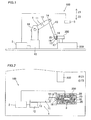
- the robot system 100 includes a robot 1, a hand portion 15 mounted on the robot 1, a robot controller 2 controlling the robot 1 and the hand portion 15, and a three-dimensional measurement unit 3 connected to the robot controller 2.
- the hand portion 15 is an example of the "robot hand”.
- a box-shaped stocker 200 in which a plurality of works 20 are arranged (stacked) randomly and a device (processing machine or the like) 300 for subsequent steps applying a prescribed treatment (processing treatment for increasing dimensional accuracy, for example) to a work 20 taken out from the stocker 200 are arranged adjacent to the robot system 100.
- the works 20 are components such as con rods (connecting rods) each having convex portions (corners) 21, a hole 22, and a bar-shaped portion 23 (see Figs. 5 to 9 ) described later.
- the works 20 are examples of the "object to be grasped".
- the robot 1 is an articulated robot including a robot arm 11.
- the robot arm 11 has a base 12, a plurality of arm portions 13 connected to the base 12 while being coupled with each other, and a plurality of joints 14 (drive joints) provided between the base 12 and the arm portions 13 connected to the base 12 and between the plurality of arm portions 13 coupled with each other.
- each of the joints 14 is configured to serve as an actuator having a servomotor and a speed reducer.
- the servomotor of each of the joints 14 is connected to be capable of communicating with the robot controller 2, and the robot controller 2 is configured to control movements of the joints 14.
- the hand portion 15 is mounted on the forward end of the robot arm 11.
- This hand portion 15 includes a pair of finger portions 16 having claw members 17, described later, to grasp the work 20.
- the finger portions 16 are examples of the "first finger portion” or the "second finger portion”.
- an unshown actuator to drive the pair of finger portions 16 is provided, and driving of this actuator is controlled by the robot controller 2.
- the pair of finger portions 16 are movable in a direction approaching each other (direction in which the work 20 is held between the claw members 17 and grasped) (along arrow A ) and a direction separating from each other (along arrow B), as shown in Fig. 3 .
- the two round bar-shaped claw members 17 each having a circular section are fixed in parallel at a prescribed interval d (see Fig. 4 ) to the forward end of each of the pair of finger portions 16, as shown in Figs. 3 and 4 .
- a prescribed clearance S into which one of the convex portions 21 of the work 20 fits is formed between the two claw members 17 provided on each of the pair of finger portions 16.
- the interval d (see Fig. 4 ) between the two claw members 17 fixed in parallel to each of the pair of finger portions 16 is set to such a size that one of the convex portions 21 of the work 20 fits thereinto when the work 20 having the convex portions 21 is held between the pair of finger portions 16 and grasped. Furthermore, the interval d (see Fig. 4 ) is set to be smaller than the diameter (the smaller outer diameter D1 of a tapered antislip portion 17b described later, the larger outer diameter D2 thereof, and the outer diameter D4 of a uniform outer diameter antislip portion 17d) of each of the claw members 17. The interval d (see Fig. 4 ) is also set to such a size that tapered antislip portions 17b, described later, of the two claw members 17 mounted on each of the pair of finger portions 16 are not in contact with each other.
- the tapered antislip portions 17b each having an outer peripheral surface to which an anti-slip treatment (double-cut knurling described later) is applied are provided in portions of the claw members 17 each having a tapered shape on the side of forward ends 17a (portions so formed that the dimensions (outer diameters) thereof in diametrical directions gradually increase from D1 to D2 toward the forward ends 17a).
- the tapered antislip portions 17b are examples of the "taper portions" or the "antislip portions”.
- Tapered portions 17c so gradually tapered that from end portions closer to the tapered antislip portions 17b toward the forward ends 17a, the dimensions (outer diameters) thereof in diametrical directions decrease from D2 to D3 are provided in portions of the claw members 17 closer to the forward ends 17a beyond the tapered antislip portions 17b.
- the tapered portions 17c are examples of the "forward end portions”.
- the inclination angles ⁇ 1 (see Fig. 4 ) of the tapered portions 17c with respect to the extensional direction (direction C) of the claw members 17 are set to be larger than the inclination angles ⁇ 2 (see Fig. 4 ) of the tapered antislip portions 17b.
- Uniform outer diameter antislip portions 17d each having an outer peripheral surface to which the anti-slip treatment (double-cut knurling described later) is applied are provided in portions of the claw members 17 closer to base ends beyond oil release groove portions 17e (opposite to the forward ends 17a of the claw members 17), extending with the uniform or substantially uniform outer diameters D4 (see Fig. 4 ).
- the outer diameter D4 (see Fig. 4 ) of each of these uniform outer diameter antislip portions 17d is set to be substantially equal to the smaller outer diameter D1 (see Fig. 4 ) of each of the tapered antislip portions 17b.
- the uniform outer diameter antislip portions 17d are examples of the "uniform outer diameter portions" or the "antislip portions".
- the "uniform outer diameter portions" do not mean that the outer diameters thereof are uniform in a mathematically strict sense, but mean that the external dimensions thereof fall within substantially the same range as compared with the tapered antislip portions 17b and the tapered portions 17c.
- Oil release groove portions 17e to release oil (not shown) applied to the work 20 are provided in the vicinity of portions of the claw members 17 coming into contact with the work 20 (boundary portions between the tapered antislip portions 17b and the uniform outer diameter antislip portions 17d).
- the oil release groove portions 17e are examples of the "groove portions”. These oil release groove portions 17e are circumferentially formed in outer peripheral portions of the claw members 17.
- the oil release groove portions 17e each has a rectangular section, and has a groove width W (see Fig. 4 ) smaller than the length L1 of each of the tapered antislip portions 17b and the length L2 of each of the uniform outer diameter antislip portions 17d in the extensional direction (direction C) of the claw members 17.
- the tapered antislip portions 17b and the uniform outer diameter antislip portions 17d are provided in the portions (see Figs. 5 to 9 ) of the claw members 17 coming into contact with the work 20. Specifically, the tapered antislip portions 17b and the uniform outer diameter antislip portions 17d are arranged in portions of the claw members 17 closer to the forward ends 17a with respect to the oil release groove portions 17e and portions of the claw members 17 closer to the finger portions 16 with respect to the oil release groove portions 17e, respectively.
- the length L1 (see Fig. 4 ) of each of the tapered antislip portions 17b in the extensional direction (direction C) of the claw members 17 is set to be larger than the length L2 (see Fig. 4 ) of each of the uniform outer diameter antislip portions 17d in the direction C.
- the tapered antislip portions 17b and the uniform outer diameter antislip portions 17d include a plurality of protrusions 17f protruding in the form of dots outward from the outer peripheral surfaces in the vicinity of the portions (see Figs. 5 to 9 ) of the claw members 17 coming into contact with the work 20.
- a plurality of grooves extending in a direction intersecting with the extensional direction (direction C) of the claw members 17 are formed at narrow intervals on the outer peripheral surfaces in the vicinity of the portions of the claw members 17 coming into contact with the work 20, and a plurality of portions surrounded by the plurality of grooves protrude outward in the form of dots, whereby the tapered antislip portions 17b and the uniform outer diameter antislip portions 17d are formed.
- the tapered antislip portions 17b and the uniform outer diameter antislip portions 17d are formed by applying the double-cut knurling to the outer peripheral surfaces in the vicinity of the portions of the claw members 17 coming into contact with the work 20.
- the three-dimensional measurement unit 3 (see Figs. 1 and 2 ) connected to the robot controller 2 measures the three-dimensional shapes of the works 20 arranged in the stocker 200 thereby detecting the arrangement states (the arrangement positions, the arrangement postures, etc.) of the works 20 arranged in the stocker 200. As shown in Fig. 1 , the three-dimensional measurement unit 3 is fixedly placed above the stocker 200 (along arrow Z1).
- the robot controller 2 chooses one (work 20 so positioned as to be most easily grasped) from the plurality of works 20 in the stocker 200 on the basis of information regarding the arrangement states (the arrangement positions, the arrangement postures, etc.) of the works 20 in the stocker 200 detected by the three-dimensional measurement unit 3, and controls the hand portion 15 to grasp the work 20. Furthermore, the robot controller 2 controls the hand portion 15 to grasp the work 20 that is an object to be grasped in a proper grasping mode (grasping mode in which the work 20 can be most stably grasped, for example) when the work 20 that is an object to be grasped is chosen as described above.
- a proper grasping mode grinding mode in which the work 20 can be most stably grasped, for example
- the robot controller 2 performs control to move the pair of finger portions 16 in the direction approaching each other (along arrow A ) while the two claw members 17 of a first finger portion of the pair of finger portions 16 of the hand portion 15 are arranged on the outer peripheral side of a convex portion (corner) 21 of the work 20 and the two claw members 17 of a second finger portion of the pair of finger portions 16 are arranged on the inner peripheral side of the hole 22 of the work 20, as shown in Fig. 5 .
- the two claw members 17 (tapered antislip portions 17b) of the first finger portion of the pair of finger portions 16 come into point contact with the outer periphery of the convex portion 21 at two points (points P1 and P2) in the vicinity of the tip of the convex portion 21 of the work 20, and the two claw members 17 (tapered antislip portions 17b) of the second finger portion come into point contact with the inner periphery of the hole 22 of the work 20 at two points (Points P3 and P4).
- the vicinity of the tip of the convex portion 21 of the work 20 is held in the clearance S between the two claw members 17 of the first finger portion in a state where the two claw members 17 of the first finger portion of the pair of finger portions 16 are arranged close to each other, and the work 20 is grasped.
- the robot controller 2 performs control to move the pair of finger portions 16 in the direction separating from each other (along arrow B) while a total of four claw members 17 mounted in pairs on the pair of finger portions 16 of the hand portion 15 are inserted into the circular hole 22 of the work 20, as shown in Fig. 6 .
- the four claw members 17 (tapered antislip portions 17b) mounted on the pair of finger portions 16 come into point contact with the inner periphery of the hole 22 of the work 20 at four points (Points P5, P6, P7, and P8). Consequently, the inner periphery of the hole 22 of the work 20 is pushed by the four claw members 17 from the inner peripheral side, and the work 20 is grasped.
- the claw members 17 may warp if the pair of finger portions 16 are further moved in the direction separating from each other (along arrow B) in a state where the four claw members 17 are in point contact with the inner periphery of the hole 22 of the work 20, as shown in Figs. 7 and 8.
- Fig. 7 shows a state where the work 20 is substantially horizontally grasped by the claw members 17.
- the tapered antislip portions 17b of the four claw members 17 are in point contact with the inner periphery of the hole 22 of the work 20 at the four points (Points P5 to P8), similarly to in the aforementioned Fig. 6.
- FIG. 8 shows a state where the work 20 is obliquely grasped by the claw members 17.
- the tapered antislip portions 17b of the two claw members 17 of the first finger portion are in point contact with the inner periphery of the hole 22 of the work 20 at two points (Points P9 and P10), similarly to in the aforementioned Figs. 6 and 7 while the uniform outer diameter antislip portions 17d of the two claw members 17 of the second finger portion are in point contact with the inner periphery of the hole 22 of the work 20 at two points (Points P11 and P12), dissimilarly to in the aforementioned Figs. 6 and 7 .
- the robot controller 2 performs control to move the pair of finger portions 16 in the direction approaching each other (along arrow A ) while the two claw members 17 of a first finger portion of the pair of finger portions 16 of the hand portion 15 are arranged on one side of the bar-shaped portion 23 of the work 20 and the two claw members 17 of a second finger portion of the pair of finger portions 16 are arranged on another side of the bar-shaped portion 23 of the work 20, as shown in Fig. 9 .
- the four claw members 17 (tapered antislip portions 17b) mounted on the pair of finger portions 16 come into point contact with the bar-shaped portion 23 of the work 20 at four points (Points P13, P14, P15, and P16). Consequently, the bar-shaped portion 23 of the work 20 is held by the four claw members 17, and the work 20 is grasped.
- the work 20 may be grasped in a grasping mode other than the aforementioned three grasping modes, but description is omitted for simplification.
- the two claw members 17 are fixed in parallel to each of the pair of finger portions 16, and the interval d (see Fig. 4 ) between the two claw members 17 is set to such a size that one of the convex portions 21 of the work 20 fits thereinto when the work 20 having the convex portions 21 is held between the pair of finger portions 16 and grasped.
- one of the convex portions 21 of the work 20 can be held in the clearance S (see Fig. 5 ) between the two claw members 17 fixed in parallel to each of the pair of finger portions 16, and hence the work 20 can be stably grasped without providing an actuator driving the two claw members 17 individually to adjust the interval d between the two claw members 17. Consequently, the work 20 can be stably grasped without complicating the structure.
- the structure of the hand portion 15 is not complicated, and hence control of the hand portion 15 by the robot controller 2 can be inhibited from complication.
- the hand portion 16 is configured to hold the vicinity of the tip of the convex portion 21 of the work 20 in the clearance S (see Fig. 5 ) between the two claw members 17 in the state where the two claw members 17 are arranged close to each other, and grasp the work 20.
- the convex portion 21 of the work 20 can be inhibited from coming off the clearance S between the two claw members 17 dissimilarly to a case where the two claw members 17 are distanced from each other, and hence the work 20 can be more stably grasped.
- the interval d (see Fig. 4 ) between the two claw members 17 is set to be smaller than the diameter (the smaller outer diameter D1 of the tapered antislip portion 17b, the larger outer diameter D2 thereof, and the outer diameter D4 of the uniform outer diameter antislip portion 17d) of each of the claw members 17.
- the tapered antislip portions 17b so formed that the outer diameters thereof increase from D1 to D2 (see Fig. 4 ) toward the forward ends 17a on the side opposite to the finger portions 16 are provided in the portions (see Fig. 5 to 9 ) of the claw members 17 coming into contact with the work 20.
- the tapered antislip portions 17b can inhibits the work 20 grasped by the claw members 17 from coming off to the side of the forward ends 17a of the claw members 17.
- the uniform outer diameter antislip portions 17d extending toward the tapered antislip portions 17b with the uniform or substantially uniform outer diameter D4 are provided in the portions of the claw members 17 closer to the finger portions 16 beyond the tapered antislip portions 17b.
- the two claw members 17 can be easily arranged parallel to each other along the extensional direction (direction C) of the uniform outer diameter antislip portions 17d, and hence the clearance S into which the convex portion 21 of the work 20 fits can be easily formed between the two claw members 17.
- the tapered portions 17c tapered from the end portions closer to the tapered antislip portions 17b toward the forward ends 17a are provided in the portions of the claw members 17 closer to the forward ends 17a beyond the tapered antislip portions 17b.
- the forward ends 17a of the claw members 17 are tapered, and hence the forward ends 17a of the claw members 17 can be smoothly inserted into the hole 22 of the work 20.
- the tapered antislip portions 17b each having the outer peripheral surface to which the anti-slip treatment (double-cut knurling) is applied are provided in the portions of the claw members 17 each having the tapered shape on the side of the forward ends 17a (portions so formed that the outer diameters thereof gradually increase from D1 to D2 toward the forward ends 17a opposite to the finger portions 16).
- the tapered antislip portions 17b can inhibit the work 20 grasped by the portions of the claw members 17 each having the tapered shape from sliding and coming off the claw members 17.
- the uniform outer diameter antislip portions 17d each having the outer peripheral surface to which the anti-slip treatment (double-cut knurling) is applied are provided in the portions of the claw members 17 closer to the finger portions 16 beyond the portions each having the tapered shape (portions of the claw members 17 extending toward the tapered antislip portions 17b with the uniform or substantially uniform outer diameters D4), similarly to the portions of the claw members 17 each having the tapered shape on the side of the forward ends 17a (portions of the claw members 17 provided with the tapered antislip portions 17b).
- the tapered antislip portions 17b and the uniform outer diameter antislip portions 17d include the plurality of protrusions 17f protruding in the form of dots.
- the plurality of protrusions 17f protruding in the form of dots can easily inhibit the work 20 grasped by the claw members 17 from sliding and coming off the claw members 17.
- the oil release groove portions 17e to release oil applied to the work 20 are provided in the vicinity of the portions of the claw members 17 coming into contact with the work 20 (boundary portions between the tapered antislip portions 17b and the uniform outer diameter antislip portions 17d).
- the oil applied to the work 20 is released into the oil release groove portions 17e, and hence the work 20 grasped by the claw members 17 can be inhibited from sliding on the oil and coming off the claw members 17.
- the oil release groove portions 17e are circumferentially formed in the outer peripheral portions of the claw members 17.
- the oil applied to the work 20 can be easily released into the oil release groove portions 17e.
- the oil release groove portions 17e each are formed to have the rectangular section.
- the sectional area of each of the oil release groove portions 17e can be rendered larger as compared with a case where the oil release groove portions 17e each are formed to have a V-shaped section, and hence a larger amount of the oil applied to the work 20 can be released into the oil release groove portions 17e.
- the hand portion 15 is configured to push the inner periphery of the hole 22 of the work 20 from the inner peripheral side by the four claw members 17 by moving the pair of finger portions 16 in the direction separating from each other (along arrow B) while the four claw members 17 mounted in pairs on the pair of finger portions 16 are inserted into the hole 22 of the work 20, and grasp the work 20.
- the work 20 having the hole 22 can be stably grasped by the four claw members 17.
- the two claw members arranged at such an interval that one of the convex portions of the work (object to be grasped) fits thereinto are provided on both of the pair of finger portions in the aforementioned embodiment, the two claw members arranged at such an interval that one of the convex portions of the object to be grasped fits thereinto may alternatively be provided on only one of the pair of finger portions.
- both of the pair of finger portions are movable in the aforementioned embodiment, only one of the pair of finger portions may alternatively be movable so far as the pair of finger portions are relatively movable in the direction in which the object to be grasped is grasped.
- the two claw members fixed in parallel to each of the pair of finger portions are arranged not to come into contact with each other in the aforementioned embodiment, the two claw members may alternatively be arranged to come into contact with each other so far as such a prescribed interval that one of the convex portions of the work (object to be grasped) fits thereinto is formed between the two claw members.
- two claw members 17 fixed in parallel to each of a pair of finger portions 116 may alternatively be arranged to come into contact with each other at end portions of tapered antislip portions 17b closer to forward ends 17a, as in a hand portion 115 according to a first modification shown in Fig. 10 .
- a clearance S1 see Fig.
- the pair of (two) finger portions are provided in the aforementioned embodiment, three or more finger portions may alternatively be provided.
- the two claw members are provided to form such a prescribed interval that one of the convex portions of the work (object to be grasped) fits thereinto in the aforementioned embodiment, three or more claw members may alternatively be provided so far as it is possible to form such a prescribed interval that one of the convex portions of the object to be grasped fits thereinto.
- a hand portion 215 according to a second modification shown in Figs. 11 to 13 three claw members 17 each having a structure similar to that of each of the claw members 17 according to the aforementioned embodiment are fixed in parallel to each of a pair of finger portions 216.
- one claw member 17 arranged at the center of the three claw members 17 mounted on each of the pair of finger portions 216 is arranged in a position deviating along arrow B from the other two claw members 17.
- a total of six claw members 17 mounted in groups of three on the pair of finger portions 216 come into point contact with a circular hole 22 of a work 20 at six points (Points Q1, Q2, Q3, Q4, Q5, and Q6) when pushing the hole 22 of the work 20 from the inner peripheral side and grasping the work 20, as shown in Fig. 12 . Consequently, the work 20 can be more stably grasped as compared with the aforementioned embodiment (see Fig. 6 ) in which the claw members 17 come into point contact with the hole 22 at the four points when pushing the hole 22 of the work 20 from the inner peripheral side and grasping the work 20.
- four claw members 17 other than two central claw members 17 arranged in positions deviating along arrow B of the six claw members 17 mounted in groups of three on the pair of finger portions 216 come into point contact with a bar-shaped portion 23 of the work 20 at four points (Points Q7, Q8, Q9, and Q10) when the six claw members 17 hold the bar-shaped portion 23 of the work 20 therebetween and grasp the work 20, as shown in Fig. 13 .
- the two claw members each are provided in the form of a round bar having a circular section in the aforementioned embodiment, the two claw members each may alternatively be provided in the form of a square bar having a rectangular section so far as it is possible to form such a prescribed interval that one of the convex portions of the work (object to be grasped) fits thereinto between the two claw members.
- taper portions, the tapered portions, and the oil release groove portions are provided in the claw members in the aforementioned embodiment, no taper portion, tapered portion, or oil release groove portion may alternatively be provided in the claw members.
- overall claw members may alternatively be constituted by uniform outer diameter portions extending from finger portions to forward ends with substantially uniform outer diameters.
- an anti-slip treatment other than the double-cut knurling may alternatively be applied to the outer peripheral surfaces of the claw members in order to form the antislip portions.
Claims (14)
- Main de robot comprenant :une première partie de doigt (16, 116, 216) et une seconde partie de doigt (16, 116, 216) qui est relativement mobile dans une direction dans laquelle un objet à saisir (20) est saisi ; etdes éléments de pince en forme de barre (17), ayant chacun une section circulaire, fixée à la première partie de doigt et à la seconde partie de doigt, dans laquelleune pluralité d'éléments de pince sont fixés parallèlement à au moins la première partie de doigt ou la seconde partie de doigt,caractérisée en ce queles éléments de pince comprennent des parties coniques (17b) formées dans une forme telle que les dimensions dans des directions diamétrales augmentent progressivement vers une extrémité avant de l'élément de pince.
- Main de robot selon la revendication 1, dans laquelle
un intervalle entre la pluralité d'éléments de pince fixés parallèlement à au moins la première partie de doigt ou la seconde partie de doigt est déterminé dans une taille telle qu'une partie convexe (21) de l'objet à saisir s'adapte dans l'intervalle lorsque l'objet à saisir ayant la partie convexe est saisi par la première partie de doigt et la seconde partie de doigt. - Main de robot selon la revendication 2, configurée pour maintenir un voisinage d'une pointe de la partie convexe de l'objet à saisir dans l'intervalle entre la pluralité d'éléments de pince dans un état dans lequel la pluralité d'éléments de pince sont agencés les uns à proximité des autres, et saisir l'objet à saisir.
- Main de robot selon la revendication 2 ou 3, dans laquelle
l'intervalle entre la pluralité d'éléments de pince est inférieur à un diamètre de chacun des éléments de pince. - Main de robot selon la revendication 1, dans laquelle
les éléments de pince comprennent en outre des parties de diamètre externes uniformes (17d) agencées dans des positions plus à proximité des extrémités de base des éléments de pince au-delà des parties coniques, s'étendant vers les parties coniques avec des diamètres externes sensiblement uniformes. - Main de robot selon la revendication 1 ou 5, dans laquelle
les éléments de pince comprennent en outre des parties d'extrémité avant (17c) dans une forme telle que les dimensions dans les directions diamétrales diminuent progressivement à partir des côtés plus à proximité des parties coniques vers les extrémités avant des éléments de pince, agencés dans des positions plus à proximité des extrémités avant des éléments de pince au-delà des parties coniques. - Main de robot selon l'une quelconque des revendications 1 à 6, dans laquelle
les parties coniques des éléments de pince ont des parties antiglisse (17b). - Main de robot selon la revendication 7, dans laquelle
les parties de diamètres externes uniformes (17d) s'étendant avec les diamètres externes sensiblement uniformes, positionnées dans les positions plus à proximité des extrémités de base des éléments de pince au-delà des parties coniques ont également des parties antiglisse (17d). - Main de robot selon la revendication 7 ou 8, dans laquelle
les parties antiglisse ont une pluralité de saillies (17f) faisant saillie sous la forme de points. - Main de robot selon l'une quelconque des revendications 1 à 9, dans laquelle
les éléments de pince comprennent des parties de rainure (17e) ayant de plus petites dimensions dans les directions diamétrales. - Main de robot selon l'une quelconque des revendications 1 à 10, dans laquelle
l'objet à saisir comprend un trou (22), et
la première partie de doigt et la seconde partie de doigt sont configurées pour être relativement mobiles dans une direction les séparant l'une de l'autre,
la main de robot étant configurée pour pousser une périphérie interne du trou de l'objet à saisir à partir d'un côté périphérique interne par les éléments de pince en déplaçant la première partie de doigt et la seconde partie de doigt dans la direction les séparant l'une de l'autre, alors que les éléments de pince fixés à la première partie de doigt et à la seconde partie de doigt sont insérées dans le trou de l'objet à saisir, et saisissant l'objet à saisir. - Robot ayant un bras de robot (11) sur lequel une main de robot (15) selon l'une quelconque des revendications 1 à 11, est montée.
- Robot selon la revendication 12, dans lequel
le bras de robot a :une base (12),une pluralité de parties de bras (13) raccordées à la base tout en étant couplées entre elles,des joints d'entraînement (14) prévus entre la base et les parties de bras raccordées à la base et entre la pluralité de parties de bras couplées entre elles, etun organe de commande de robot (2) commandant les mouvements des joints d'entraînement. - Procédé pour fabriquer une pièce à usiner, qui est un procédé pour fabriquer une pièce à usiner utilisant une main de robot (15, 115, 215) selon l'une quelconque des revendications 1 à 11, comprenant les étapes consistant à :saisir et prendre l'objet à saisir par les éléments de pince fixés sur la première partie de doigt et la seconde partie de doigt de la main de robot ; etappliquer un traitement prédéterminé sur l'objet à saisir, pris par la main de robot.
Applications Claiming Priority (1)
| Application Number | Priority Date | Filing Date | Title |
|---|---|---|---|
| JP2012115658A JP5594317B2 (ja) | 2012-05-21 | 2012-05-21 | ロボットハンド、ロボットシステムおよび加工品の製造方法 |
Publications (2)
| Publication Number | Publication Date |
|---|---|
| EP2666599A1 EP2666599A1 (fr) | 2013-11-27 |
| EP2666599B1 true EP2666599B1 (fr) | 2015-09-09 |
Family
ID=47722045
Family Applications (1)
| Application Number | Title | Priority Date | Filing Date |
|---|---|---|---|
| EP13154359.7A Not-in-force EP2666599B1 (fr) | 2012-05-21 | 2013-02-07 | Main de robot, robot et procédé de fabrication de pièce à usiner |
Country Status (4)
| Country | Link |
|---|---|
| US (1) | US8936291B2 (fr) |
| EP (1) | EP2666599B1 (fr) |
| JP (1) | JP5594317B2 (fr) |
| CN (2) | CN103419209B (fr) |
Families Citing this family (20)
| Publication number | Priority date | Publication date | Assignee | Title |
|---|---|---|---|---|
| FR3017559B1 (fr) * | 2014-02-19 | 2019-05-17 | Etude Conception Outillage Traitements De Surfaces | Outil de manipulation d'un objet. |
| CH709307A1 (de) | 2014-02-26 | 2015-08-28 | Tecan Trading Ag | Transportwerkzeug zum Transportieren eines Laborartikels. |
| DE102014220790A1 (de) * | 2014-10-14 | 2016-04-14 | Continental Automotive Gmbh | Vorrichtung und Verfahren für das Installieren und Entfernen einer elektronischen Komponente für einen Reifen |
| EP3206953B1 (fr) * | 2014-10-15 | 2018-09-26 | Bema S.r.l. | Groupe de positionnement d'éléments de protection dans un emballage rigide et procédé de positionnement de tels éléments de protection |
| DE102015107470A1 (de) * | 2015-05-12 | 2016-11-17 | Trumpf Gmbh + Co. Kg | Verfahren und Vorrichtung zum Abführen eines Werkstücks mit einem unebenen oder konturierten Flächenabschnitt aus einer Bearbeitungsmaschine |
| US10081064B2 (en) * | 2015-08-19 | 2018-09-25 | GM Global Technology Operations LLC | Expanding locating and clamping pin |
| US11370128B2 (en) | 2015-09-01 | 2022-06-28 | Berkshire Grey Operating Company, Inc. | Systems and methods for providing dynamic robotic control systems |
| EP4137280A1 (fr) | 2015-09-01 | 2023-02-22 | Berkshire Grey Operating Company, Inc. | Systèmes et procédés pour fournir des systèmes de commande robotique dynamique |
| JP6164434B2 (ja) * | 2015-10-14 | 2017-07-19 | 広島県 | エンドエフェクタ |
| EP3368907B1 (fr) * | 2015-10-30 | 2021-09-08 | Thermo Fisher Scientific Oy | Doigt d'élément de préhension et élément de préhension |
| CA3107257C (fr) | 2015-11-13 | 2023-05-02 | Berkshire Grey, Inc. | Systemes de tri et procedes pour assurer le tri de divers objets |
| EP3661705B1 (fr) | 2017-08-02 | 2024-01-03 | Berkshire Grey Operating Company, Inc. | Systèmes et procédés d'acquisition et de déplacement d'objets présentant des surfaces extérieures complexes |
| WO2019058470A1 (fr) * | 2017-09-21 | 2019-03-28 | 株式会社Fuji | Mandrin permettant de maintenir un composant de montage, et machine de montage de composants |
| US10500735B1 (en) | 2018-07-13 | 2019-12-10 | Dexterity, Inc. | Robotic toolset and gripper |
| DE102019204393B4 (de) * | 2019-03-28 | 2022-12-22 | Körber Supply Chain Automation Eisenberg GmbH | Greiferelemente für Handhabungseinrichtungen |
| CN110103209A (zh) * | 2019-06-03 | 2019-08-09 | 临沂大学 | 手套上模装置 |
| US11302134B2 (en) * | 2019-07-23 | 2022-04-12 | Japan Cash Machine Co., Ltd. | Automatic bill handling system |
| JP7165284B2 (ja) * | 2020-02-27 | 2022-11-02 | ジヤトコ株式会社 | ワーク把持機構 |
| CN113401853B (zh) * | 2021-06-23 | 2023-03-24 | 中国核动力研究设计院 | 一种用于干燥盐桶的开盖和封盖装置 |
| WO2023106041A1 (fr) * | 2021-12-08 | 2023-06-15 | 株式会社村田製作所 | Dispositif de manipulation |
Family Cites Families (21)
| Publication number | Priority date | Publication date | Assignee | Title |
|---|---|---|---|---|
| US3139302A (en) * | 1961-09-08 | 1964-06-30 | Molins Machine Co Ltd | Mechanical handling apparatus |
| US5108140A (en) * | 1988-04-18 | 1992-04-28 | Odetics, Inc. | Reconfigurable end effector |
| US5762390A (en) * | 1996-07-16 | 1998-06-09 | Universite Laval | Underactuated mechanical finger with return actuation |
| JPH10249775A (ja) * | 1997-03-11 | 1998-09-22 | Kubota Corp | ロボットハンド用指 |
| US6015174A (en) | 1998-06-04 | 2000-01-18 | Eastman Kodak Company | Universal end effector for robotic applications |
| US6435582B1 (en) * | 2000-07-31 | 2002-08-20 | Motoman, Inc. | Object manipulator and manipulation system |
| JP3715266B2 (ja) | 2002-08-30 | 2005-11-09 | 株式会社アイディエス | 検体容器チャック機構 |
| JP4525117B2 (ja) * | 2004-03-12 | 2010-08-18 | ルネサスエレクトロニクス株式会社 | トレイ |
| JP2007222971A (ja) * | 2006-02-22 | 2007-09-06 | Nissan Motor Co Ltd | ロボットハンドとロボットハンドのフィンガー交換装置 |
| JP4918004B2 (ja) * | 2006-11-24 | 2012-04-18 | パナソニック株式会社 | 多指ロボットハンド |
| DE602006019509D1 (de) | 2006-12-04 | 2011-02-17 | Inpeco Ip Ltd | Mit einem positionssensor ausgestatteter behältergreifer |
| JP2009154253A (ja) | 2007-12-27 | 2009-07-16 | Nachi Fujikoshi Corp | 産業用ロボットのハンド装置 |
| CN101543993B (zh) * | 2008-03-25 | 2012-03-28 | 鸿富锦精密工业(深圳)有限公司 | 机械手 |
| JP2010131743A (ja) | 2008-10-30 | 2010-06-17 | Canon Inc | 力覚センサを内蔵した把持装置 |
| JP5479834B2 (ja) * | 2009-09-30 | 2014-04-23 | 川崎重工業株式会社 | ピッキング方法 |
| JP2011177863A (ja) | 2010-03-03 | 2011-09-15 | Ihi Corp | 把持装置 |
| JP5229253B2 (ja) | 2010-03-11 | 2013-07-03 | 株式会社安川電機 | ロボットシステム及びロボット装置並びにワーク取り出し方法 |
| JP5416642B2 (ja) | 2010-04-02 | 2014-02-12 | 川崎重工業株式会社 | ロボットハンドのフィンガ構造 |
| JP2011230239A (ja) | 2010-04-28 | 2011-11-17 | Honda Motor Co Ltd | ワークの把持方法 |
| CN201720848U (zh) * | 2010-05-14 | 2011-01-26 | 上海普莱克斯自动设备制造有限公司 | 气缸内置式二爪抓手 |
| JP5574103B2 (ja) * | 2010-07-23 | 2014-08-20 | 株式会社Ihi | 把持搬送装置 |
-
2012
- 2012-05-21 JP JP2012115658A patent/JP5594317B2/ja not_active Expired - Fee Related
-
2013
- 2013-02-06 US US13/760,070 patent/US8936291B2/en not_active Expired - Fee Related
- 2013-02-07 EP EP13154359.7A patent/EP2666599B1/fr not_active Not-in-force
- 2013-02-27 CN CN201310061073.7A patent/CN103419209B/zh not_active Expired - Fee Related
- 2013-02-27 CN CN 201320088811 patent/CN203344057U/zh not_active Expired - Fee Related
Also Published As
| Publication number | Publication date |
|---|---|
| JP5594317B2 (ja) | 2014-09-24 |
| CN103419209A (zh) | 2013-12-04 |
| US20130309057A1 (en) | 2013-11-21 |
| CN103419209B (zh) | 2015-11-18 |
| US8936291B2 (en) | 2015-01-20 |
| EP2666599A1 (fr) | 2013-11-27 |
| JP2013240859A (ja) | 2013-12-05 |
| CN203344057U (zh) | 2013-12-18 |
Similar Documents
| Publication | Publication Date | Title |
|---|---|---|
| EP2666599B1 (fr) | Main de robot, robot et procédé de fabrication de pièce à usiner | |
| US10035262B2 (en) | Robotic gripper with multiple pairs of gripping fingers | |
| US10076841B2 (en) | Method and device for controlling a manipulator | |
| US8788093B2 (en) | Human robot interactive system | |
| KR102115983B1 (ko) | 컨테이너 내에 배치된 공작물을 자동으로 제거하기 위한 장치 | |
| EP1714750B1 (fr) | Main de robot comprenant des éléments de préhension | |
| US20110175274A1 (en) | Production system | |
| US9757863B2 (en) | Robot apparatus, exchanger apparatus and robot system | |
| US20170173789A1 (en) | Adaptable end effector and method | |
| US8360377B2 (en) | Tool mounting device | |
| JP6878027B2 (ja) | ロボットハンド、ロボットハンドの制御方法、ロボットハンドを用いた物品の製造方法、ロボット装置、制御プログラムおよび記録媒体 | |
| TWI613053B (zh) | 工件搬送系統 | |
| US11167434B2 (en) | Robotic processing system | |
| JP2015085481A (ja) | ロボット、ロボットシステム、ロボット制御部及び把持方法 | |
| JP2020049582A (ja) | エンドエフェクタ装置 | |
| WO2020066061A1 (fr) | Effecteur terminal et dispositif à effecteur terminal | |
| JP2016032865A (ja) | ロボットハンド | |
| JP6554784B2 (ja) | ロボットハンド、ロボット及びロボットシステム | |
| JP2015074065A (ja) | ロボット及び取り出し方法 | |
| US11034528B2 (en) | Workpiece holding jig | |
| JP6354315B2 (ja) | ロボットハンド及びこれを備えた自動組立ロボット | |
| WO2021029168A1 (fr) | Dispositif de commande de robot, robot, et procédé de commande de robot | |
| JP2018130794A (ja) | ワーク保持部材、及びそれを用いるワーク回転装置 | |
| US20230071893A1 (en) | Robotic gripper apparatus | |
| JP2023036277A (ja) | ロボット、ロボットの制御方法、及びプログラム |
Legal Events
| Date | Code | Title | Description |
|---|---|---|---|
| PUAI | Public reference made under article 153(3) epc to a published international application that has entered the european phase |
Free format text: ORIGINAL CODE: 0009012 |
|
| AK | Designated contracting states |
Kind code of ref document: A1 Designated state(s): AL AT BE BG CH CY CZ DE DK EE ES FI FR GB GR HR HU IE IS IT LI LT LU LV MC MK MT NL NO PL PT RO RS SE SI SK SM TR |
|
| AX | Request for extension of the european patent |
Extension state: BA ME |
|
| 17P | Request for examination filed |
Effective date: 20140527 |
|
| RBV | Designated contracting states (corrected) |
Designated state(s): AL AT BE BG CH CY CZ DE DK EE ES FI FR GB GR HR HU IE IS IT LI LT LU LV MC MK MT NL NO PL PT RO RS SE SI SK SM TR |
|
| GRAP | Despatch of communication of intention to grant a patent |
Free format text: ORIGINAL CODE: EPIDOSNIGR1 |
|
| INTG | Intention to grant announced |
Effective date: 20150323 |
|
| GRAS | Grant fee paid |
Free format text: ORIGINAL CODE: EPIDOSNIGR3 |
|
| GRAA | (expected) grant |
Free format text: ORIGINAL CODE: 0009210 |
|
| AK | Designated contracting states |
Kind code of ref document: B1 Designated state(s): AL AT BE BG CH CY CZ DE DK EE ES FI FR GB GR HR HU IE IS IT LI LT LU LV MC MK MT NL NO PL PT RO RS SE SI SK SM TR |
|
| REG | Reference to a national code |
Ref country code: GB Ref legal event code: FG4D |
|
| REG | Reference to a national code |
Ref country code: AT Ref legal event code: REF Ref document number: 747741 Country of ref document: AT Kind code of ref document: T Effective date: 20150915 Ref country code: CH Ref legal event code: EP |
|
| REG | Reference to a national code |
Ref country code: IE Ref legal event code: FG4D |
|
| REG | Reference to a national code |
Ref country code: DE Ref legal event code: R096 Ref document number: 602013002874 Country of ref document: DE |
|
| REG | Reference to a national code |
Ref country code: NL Ref legal event code: MP Effective date: 20150909 |
|
| PG25 | Lapsed in a contracting state [announced via postgrant information from national office to epo] |
Ref country code: GR Free format text: LAPSE BECAUSE OF FAILURE TO SUBMIT A TRANSLATION OF THE DESCRIPTION OR TO PAY THE FEE WITHIN THE PRESCRIBED TIME-LIMIT Effective date: 20151210 Ref country code: FI Free format text: LAPSE BECAUSE OF FAILURE TO SUBMIT A TRANSLATION OF THE DESCRIPTION OR TO PAY THE FEE WITHIN THE PRESCRIBED TIME-LIMIT Effective date: 20150909 Ref country code: LV Free format text: LAPSE BECAUSE OF FAILURE TO SUBMIT A TRANSLATION OF THE DESCRIPTION OR TO PAY THE FEE WITHIN THE PRESCRIBED TIME-LIMIT Effective date: 20150909 Ref country code: LT Free format text: LAPSE BECAUSE OF FAILURE TO SUBMIT A TRANSLATION OF THE DESCRIPTION OR TO PAY THE FEE WITHIN THE PRESCRIBED TIME-LIMIT Effective date: 20150909 Ref country code: NO Free format text: LAPSE BECAUSE OF FAILURE TO SUBMIT A TRANSLATION OF THE DESCRIPTION OR TO PAY THE FEE WITHIN THE PRESCRIBED TIME-LIMIT Effective date: 20151209 |
|
| REG | Reference to a national code |
Ref country code: LT Ref legal event code: MG4D |
|
| REG | Reference to a national code |
Ref country code: AT Ref legal event code: MK05 Ref document number: 747741 Country of ref document: AT Kind code of ref document: T Effective date: 20150909 |
|
| PG25 | Lapsed in a contracting state [announced via postgrant information from national office to epo] |
Ref country code: ES Free format text: LAPSE BECAUSE OF FAILURE TO SUBMIT A TRANSLATION OF THE DESCRIPTION OR TO PAY THE FEE WITHIN THE PRESCRIBED TIME-LIMIT Effective date: 20150909 Ref country code: RS Free format text: LAPSE BECAUSE OF FAILURE TO SUBMIT A TRANSLATION OF THE DESCRIPTION OR TO PAY THE FEE WITHIN THE PRESCRIBED TIME-LIMIT Effective date: 20150909 Ref country code: HR Free format text: LAPSE BECAUSE OF FAILURE TO SUBMIT A TRANSLATION OF THE DESCRIPTION OR TO PAY THE FEE WITHIN THE PRESCRIBED TIME-LIMIT Effective date: 20150909 Ref country code: SE Free format text: LAPSE BECAUSE OF FAILURE TO SUBMIT A TRANSLATION OF THE DESCRIPTION OR TO PAY THE FEE WITHIN THE PRESCRIBED TIME-LIMIT Effective date: 20150909 |
|
| PG25 | Lapsed in a contracting state [announced via postgrant information from national office to epo] |
Ref country code: NL Free format text: LAPSE BECAUSE OF FAILURE TO SUBMIT A TRANSLATION OF THE DESCRIPTION OR TO PAY THE FEE WITHIN THE PRESCRIBED TIME-LIMIT Effective date: 20150909 |
|
| PG25 | Lapsed in a contracting state [announced via postgrant information from national office to epo] |
Ref country code: SK Free format text: LAPSE BECAUSE OF FAILURE TO SUBMIT A TRANSLATION OF THE DESCRIPTION OR TO PAY THE FEE WITHIN THE PRESCRIBED TIME-LIMIT Effective date: 20150909 Ref country code: CZ Free format text: LAPSE BECAUSE OF FAILURE TO SUBMIT A TRANSLATION OF THE DESCRIPTION OR TO PAY THE FEE WITHIN THE PRESCRIBED TIME-LIMIT Effective date: 20150909 Ref country code: IS Free format text: LAPSE BECAUSE OF FAILURE TO SUBMIT A TRANSLATION OF THE DESCRIPTION OR TO PAY THE FEE WITHIN THE PRESCRIBED TIME-LIMIT Effective date: 20160109 Ref country code: EE Free format text: LAPSE BECAUSE OF FAILURE TO SUBMIT A TRANSLATION OF THE DESCRIPTION OR TO PAY THE FEE WITHIN THE PRESCRIBED TIME-LIMIT Effective date: 20150909 Ref country code: IT Free format text: LAPSE BECAUSE OF FAILURE TO SUBMIT A TRANSLATION OF THE DESCRIPTION OR TO PAY THE FEE WITHIN THE PRESCRIBED TIME-LIMIT Effective date: 20150909 |
|
| PG25 | Lapsed in a contracting state [announced via postgrant information from national office to epo] |
Ref country code: AT Free format text: LAPSE BECAUSE OF FAILURE TO SUBMIT A TRANSLATION OF THE DESCRIPTION OR TO PAY THE FEE WITHIN THE PRESCRIBED TIME-LIMIT Effective date: 20150909 Ref country code: PL Free format text: LAPSE BECAUSE OF FAILURE TO SUBMIT A TRANSLATION OF THE DESCRIPTION OR TO PAY THE FEE WITHIN THE PRESCRIBED TIME-LIMIT Effective date: 20150909 Ref country code: BE Free format text: LAPSE BECAUSE OF NON-PAYMENT OF DUE FEES Effective date: 20160229 Ref country code: PT Free format text: LAPSE BECAUSE OF FAILURE TO SUBMIT A TRANSLATION OF THE DESCRIPTION OR TO PAY THE FEE WITHIN THE PRESCRIBED TIME-LIMIT Effective date: 20160111 Ref country code: RO Free format text: LAPSE BECAUSE OF FAILURE TO SUBMIT A TRANSLATION OF THE DESCRIPTION OR TO PAY THE FEE WITHIN THE PRESCRIBED TIME-LIMIT Effective date: 20150909 |
|
| REG | Reference to a national code |
Ref country code: DE Ref legal event code: R097 Ref document number: 602013002874 Country of ref document: DE |
|
| PLBE | No opposition filed within time limit |
Free format text: ORIGINAL CODE: 0009261 |
|
| STAA | Information on the status of an ep patent application or granted ep patent |
Free format text: STATUS: NO OPPOSITION FILED WITHIN TIME LIMIT |
|
| 26N | No opposition filed |
Effective date: 20160610 |
|
| PG25 | Lapsed in a contracting state [announced via postgrant information from national office to epo] |
Ref country code: DK Free format text: LAPSE BECAUSE OF FAILURE TO SUBMIT A TRANSLATION OF THE DESCRIPTION OR TO PAY THE FEE WITHIN THE PRESCRIBED TIME-LIMIT Effective date: 20150909 Ref country code: SI Free format text: LAPSE BECAUSE OF FAILURE TO SUBMIT A TRANSLATION OF THE DESCRIPTION OR TO PAY THE FEE WITHIN THE PRESCRIBED TIME-LIMIT Effective date: 20150909 |
|
| PG25 | Lapsed in a contracting state [announced via postgrant information from national office to epo] |
Ref country code: LU Free format text: LAPSE BECAUSE OF FAILURE TO SUBMIT A TRANSLATION OF THE DESCRIPTION OR TO PAY THE FEE WITHIN THE PRESCRIBED TIME-LIMIT Effective date: 20160207 Ref country code: MC Free format text: LAPSE BECAUSE OF FAILURE TO SUBMIT A TRANSLATION OF THE DESCRIPTION OR TO PAY THE FEE WITHIN THE PRESCRIBED TIME-LIMIT Effective date: 20150909 |
|
| REG | Reference to a national code |
Ref country code: CH Ref legal event code: PL |
|
| PG25 | Lapsed in a contracting state [announced via postgrant information from national office to epo] |
Ref country code: CH Free format text: LAPSE BECAUSE OF NON-PAYMENT OF DUE FEES Effective date: 20160229 Ref country code: LI Free format text: LAPSE BECAUSE OF NON-PAYMENT OF DUE FEES Effective date: 20160229 |
|
| REG | Reference to a national code |
Ref country code: FR Ref legal event code: ST Effective date: 20161028 |
|
| REG | Reference to a national code |
Ref country code: IE Ref legal event code: MM4A |
|
| PG25 | Lapsed in a contracting state [announced via postgrant information from national office to epo] |
Ref country code: BE Free format text: LAPSE BECAUSE OF FAILURE TO SUBMIT A TRANSLATION OF THE DESCRIPTION OR TO PAY THE FEE WITHIN THE PRESCRIBED TIME-LIMIT Effective date: 20150909 |
|
| PG25 | Lapsed in a contracting state [announced via postgrant information from national office to epo] |
Ref country code: FR Free format text: LAPSE BECAUSE OF NON-PAYMENT OF DUE FEES Effective date: 20160229 Ref country code: IE Free format text: LAPSE BECAUSE OF NON-PAYMENT OF DUE FEES Effective date: 20160207 |
|
| PGFP | Annual fee paid to national office [announced via postgrant information from national office to epo] |
Ref country code: DE Payment date: 20170131 Year of fee payment: 5 |
|
| PG25 | Lapsed in a contracting state [announced via postgrant information from national office to epo] |
Ref country code: MT Free format text: LAPSE BECAUSE OF FAILURE TO SUBMIT A TRANSLATION OF THE DESCRIPTION OR TO PAY THE FEE WITHIN THE PRESCRIBED TIME-LIMIT Effective date: 20150909 |
|
| GBPC | Gb: european patent ceased through non-payment of renewal fee |
Effective date: 20170207 |
|
| PG25 | Lapsed in a contracting state [announced via postgrant information from national office to epo] |
Ref country code: GB Free format text: LAPSE BECAUSE OF NON-PAYMENT OF DUE FEES Effective date: 20170207 |
|
| PG25 | Lapsed in a contracting state [announced via postgrant information from national office to epo] |
Ref country code: CY Free format text: LAPSE BECAUSE OF FAILURE TO SUBMIT A TRANSLATION OF THE DESCRIPTION OR TO PAY THE FEE WITHIN THE PRESCRIBED TIME-LIMIT Effective date: 20150909 Ref country code: HU Free format text: LAPSE BECAUSE OF FAILURE TO SUBMIT A TRANSLATION OF THE DESCRIPTION OR TO PAY THE FEE WITHIN THE PRESCRIBED TIME-LIMIT; INVALID AB INITIO Effective date: 20130207 Ref country code: SM Free format text: LAPSE BECAUSE OF FAILURE TO SUBMIT A TRANSLATION OF THE DESCRIPTION OR TO PAY THE FEE WITHIN THE PRESCRIBED TIME-LIMIT Effective date: 20150909 |
|
| PG25 | Lapsed in a contracting state [announced via postgrant information from national office to epo] |
Ref country code: MK Free format text: LAPSE BECAUSE OF FAILURE TO SUBMIT A TRANSLATION OF THE DESCRIPTION OR TO PAY THE FEE WITHIN THE PRESCRIBED TIME-LIMIT Effective date: 20150909 Ref country code: TR Free format text: LAPSE BECAUSE OF FAILURE TO SUBMIT A TRANSLATION OF THE DESCRIPTION OR TO PAY THE FEE WITHIN THE PRESCRIBED TIME-LIMIT Effective date: 20150909 Ref country code: MT Free format text: LAPSE BECAUSE OF FAILURE TO SUBMIT A TRANSLATION OF THE DESCRIPTION OR TO PAY THE FEE WITHIN THE PRESCRIBED TIME-LIMIT Effective date: 20160229 |
|
| PG25 | Lapsed in a contracting state [announced via postgrant information from national office to epo] |
Ref country code: BG Free format text: LAPSE BECAUSE OF FAILURE TO SUBMIT A TRANSLATION OF THE DESCRIPTION OR TO PAY THE FEE WITHIN THE PRESCRIBED TIME-LIMIT Effective date: 20150909 |
|
| REG | Reference to a national code |
Ref country code: DE Ref legal event code: R119 Ref document number: 602013002874 Country of ref document: DE |
|
| PG25 | Lapsed in a contracting state [announced via postgrant information from national office to epo] |
Ref country code: AL Free format text: LAPSE BECAUSE OF FAILURE TO SUBMIT A TRANSLATION OF THE DESCRIPTION OR TO PAY THE FEE WITHIN THE PRESCRIBED TIME-LIMIT Effective date: 20150909 |
|
| PG25 | Lapsed in a contracting state [announced via postgrant information from national office to epo] |
Ref country code: DE Free format text: LAPSE BECAUSE OF NON-PAYMENT OF DUE FEES Effective date: 20180901 |