EP2663014A2 - Procédé et appareil pour la transmission et la réception de flux de données dans des systèmes de diffusion vidéo numérique - Google Patents
Procédé et appareil pour la transmission et la réception de flux de données dans des systèmes de diffusion vidéo numérique Download PDFInfo
- Publication number
- EP2663014A2 EP2663014A2 EP13162559.2A EP13162559A EP2663014A2 EP 2663014 A2 EP2663014 A2 EP 2663014A2 EP 13162559 A EP13162559 A EP 13162559A EP 2663014 A2 EP2663014 A2 EP 2663014A2
- Authority
- EP
- European Patent Office
- Prior art keywords
- logical
- frame
- plp
- frames
- data
- Prior art date
- Legal status (The legal status is an assumption and is not a legal conclusion. Google has not performed a legal analysis and makes no representation as to the accuracy of the status listed.)
- Granted
Links
- 238000000034 method Methods 0.000 title claims abstract description 125
- 230000005540 biological transmission Effects 0.000 title claims description 82
- 238000004891 communication Methods 0.000 claims abstract description 40
- 238000013507 mapping Methods 0.000 claims abstract description 33
- 230000011664 signaling Effects 0.000 claims description 188
- NGVDGCNFYWLIFO-UHFFFAOYSA-N pyridoxal 5'-phosphate Chemical compound CC1=NC=C(COP(O)(O)=O)C(C=O)=C1O NGVDGCNFYWLIFO-UHFFFAOYSA-N 0.000 claims description 14
- 230000032258 transport Effects 0.000 claims description 14
- 238000012937 correction Methods 0.000 claims description 5
- 210000004027 cell Anatomy 0.000 description 80
- 230000008569 process Effects 0.000 description 48
- 238000010586 diagram Methods 0.000 description 31
- 238000005192 partition Methods 0.000 description 28
- 238000012545 processing Methods 0.000 description 21
- 238000000638 solvent extraction Methods 0.000 description 12
- 230000006870 function Effects 0.000 description 10
- 230000007246 mechanism Effects 0.000 description 7
- 230000008859 change Effects 0.000 description 6
- 238000004590 computer program Methods 0.000 description 5
- 239000011159 matrix material Substances 0.000 description 5
- 230000009467 reduction Effects 0.000 description 5
- 230000008054 signal transmission Effects 0.000 description 5
- 239000000284 extract Substances 0.000 description 4
- 230000001360 synchronised effect Effects 0.000 description 4
- 230000008901 benefit Effects 0.000 description 3
- 238000013500 data storage Methods 0.000 description 3
- 230000001934 delay Effects 0.000 description 3
- 230000003287 optical effect Effects 0.000 description 3
- 230000001174 ascending effect Effects 0.000 description 2
- 238000013461 design Methods 0.000 description 2
- 238000003780 insertion Methods 0.000 description 2
- 230000037431 insertion Effects 0.000 description 2
- 238000005259 measurement Methods 0.000 description 2
- 210000004457 myocytus nodalis Anatomy 0.000 description 2
- 230000002829 reductive effect Effects 0.000 description 2
- 230000004044 response Effects 0.000 description 2
- 230000002441 reversible effect Effects 0.000 description 2
- 239000004065 semiconductor Substances 0.000 description 2
- 230000003068 static effect Effects 0.000 description 2
- LTLZXJXSDAEXDQ-UHFFFAOYSA-N 6,13-bis[2,6-di(propan-2-yl)phenyl]-6,13-diazatetracyclo[6.6.2.04,16.011,15]hexadeca-1(15),2,4(16),8,10-pentaene-5,7,12,14-tetrone Chemical compound CC(C)C1=CC=CC(C(C)C)=C1N(C1=O)C(=O)C(C=C2)=C3C1=CC=C1C(=O)N(C=4C(=CC=CC=4C(C)C)C(C)C)C(=O)C2=C31 LTLZXJXSDAEXDQ-UHFFFAOYSA-N 0.000 description 1
- 102100036570 Coiled-coil domain-containing protein 177 Human genes 0.000 description 1
- 101000715214 Homo sapiens Coiled-coil domain-containing protein 177 Proteins 0.000 description 1
- 230000004075 alteration Effects 0.000 description 1
- 230000015556 catabolic process Effects 0.000 description 1
- 230000001413 cellular effect Effects 0.000 description 1
- 238000006243 chemical reaction Methods 0.000 description 1
- 230000006835 compression Effects 0.000 description 1
- 238000007906 compression Methods 0.000 description 1
- 238000010276 construction Methods 0.000 description 1
- 125000004122 cyclic group Chemical group 0.000 description 1
- 230000007812 deficiency Effects 0.000 description 1
- 238000006731 degradation reaction Methods 0.000 description 1
- 238000001514 detection method Methods 0.000 description 1
- 230000000694 effects Effects 0.000 description 1
- 239000000835 fiber Substances 0.000 description 1
- 238000001914 filtration Methods 0.000 description 1
- 238000002955 isolation Methods 0.000 description 1
- 230000000670 limiting effect Effects 0.000 description 1
- 238000012986 modification Methods 0.000 description 1
- 230000004048 modification Effects 0.000 description 1
- 230000008520 organization Effects 0.000 description 1
- 230000008707 rearrangement Effects 0.000 description 1
- 230000036962 time dependent Effects 0.000 description 1
Images


Classifications
-
- H—ELECTRICITY
- H04—ELECTRIC COMMUNICATION TECHNIQUE
- H04H—BROADCAST COMMUNICATION
- H04H20/00—Arrangements for broadcast or for distribution combined with broadcast
- H04H20/65—Arrangements characterised by transmission systems for broadcast
- H04H20/71—Wireless systems
-
- H—ELECTRICITY
- H04—ELECTRIC COMMUNICATION TECHNIQUE
- H04H—BROADCAST COMMUNICATION
- H04H20/00—Arrangements for broadcast or for distribution combined with broadcast
- H04H20/53—Arrangements specially adapted for specific applications, e.g. for traffic information or for mobile receivers
-
- H—ELECTRICITY
- H04—ELECTRIC COMMUNICATION TECHNIQUE
- H04H—BROADCAST COMMUNICATION
- H04H20/00—Arrangements for broadcast or for distribution combined with broadcast
- H04H20/53—Arrangements specially adapted for specific applications, e.g. for traffic information or for mobile receivers
- H04H20/57—Arrangements specially adapted for specific applications, e.g. for traffic information or for mobile receivers for mobile receivers
-
- H—ELECTRICITY
- H04—ELECTRIC COMMUNICATION TECHNIQUE
- H04L—TRANSMISSION OF DIGITAL INFORMATION, e.g. TELEGRAPHIC COMMUNICATION
- H04L27/00—Modulated-carrier systems
- H04L27/26—Systems using multi-frequency codes
- H04L27/2601—Multicarrier modulation systems
- H04L27/2602—Signal structure
-
- H—ELECTRICITY
- H04—ELECTRIC COMMUNICATION TECHNIQUE
- H04L—TRANSMISSION OF DIGITAL INFORMATION, e.g. TELEGRAPHIC COMMUNICATION
- H04L5/00—Arrangements affording multiple use of the transmission path
- H04L5/003—Arrangements for allocating sub-channels of the transmission path
- H04L5/0053—Allocation of signaling, i.e. of overhead other than pilot signals
-
- H—ELECTRICITY
- H04—ELECTRIC COMMUNICATION TECHNIQUE
- H04L—TRANSMISSION OF DIGITAL INFORMATION, e.g. TELEGRAPHIC COMMUNICATION
- H04L5/00—Arrangements affording multiple use of the transmission path
- H04L5/003—Arrangements for allocating sub-channels of the transmission path
- H04L5/0058—Allocation criteria
- H04L5/0064—Rate requirement of the data, e.g. scalable bandwidth, data priority
-
- H—ELECTRICITY
- H04—ELECTRIC COMMUNICATION TECHNIQUE
- H04L—TRANSMISSION OF DIGITAL INFORMATION, e.g. TELEGRAPHIC COMMUNICATION
- H04L65/00—Network arrangements, protocols or services for supporting real-time applications in data packet communication
- H04L65/60—Network streaming of media packets
-
- H—ELECTRICITY
- H04—ELECTRIC COMMUNICATION TECHNIQUE
- H04N—PICTORIAL COMMUNICATION, e.g. TELEVISION
- H04N21/00—Selective content distribution, e.g. interactive television or video on demand [VOD]
- H04N21/20—Servers specifically adapted for the distribution of content, e.g. VOD servers; Operations thereof
- H04N21/23—Processing of content or additional data; Elementary server operations; Server middleware
- H04N21/236—Assembling of a multiplex stream, e.g. transport stream, by combining a video stream with other content or additional data, e.g. inserting a URL [Uniform Resource Locator] into a video stream, multiplexing software data into a video stream; Remultiplexing of multiplex streams; Insertion of stuffing bits into the multiplex stream, e.g. to obtain a constant bit-rate; Assembling of a packetised elementary stream
- H04N21/2362—Generation or processing of Service Information [SI]
-
- H—ELECTRICITY
- H04—ELECTRIC COMMUNICATION TECHNIQUE
- H04N—PICTORIAL COMMUNICATION, e.g. TELEVISION
- H04N21/00—Selective content distribution, e.g. interactive television or video on demand [VOD]
- H04N21/20—Servers specifically adapted for the distribution of content, e.g. VOD servers; Operations thereof
- H04N21/23—Processing of content or additional data; Elementary server operations; Server middleware
- H04N21/238—Interfacing the downstream path of the transmission network, e.g. adapting the transmission rate of a video stream to network bandwidth; Processing of multiplex streams
- H04N21/2381—Adapting the multiplex stream to a specific network, e.g. an Internet Protocol [IP] network
-
- H—ELECTRICITY
- H04—ELECTRIC COMMUNICATION TECHNIQUE
- H04N—PICTORIAL COMMUNICATION, e.g. TELEVISION
- H04N21/00—Selective content distribution, e.g. interactive television or video on demand [VOD]
- H04N21/60—Network structure or processes for video distribution between server and client or between remote clients; Control signalling between clients, server and network components; Transmission of management data between server and client, e.g. sending from server to client commands for recording incoming content stream; Communication details between server and client
- H04N21/61—Network physical structure; Signal processing
- H04N21/6106—Network physical structure; Signal processing specially adapted to the downstream path of the transmission network
- H04N21/6112—Network physical structure; Signal processing specially adapted to the downstream path of the transmission network involving terrestrial transmission, e.g. DVB-T
-
- H—ELECTRICITY
- H04—ELECTRIC COMMUNICATION TECHNIQUE
- H04N—PICTORIAL COMMUNICATION, e.g. TELEVISION
- H04N21/00—Selective content distribution, e.g. interactive television or video on demand [VOD]
- H04N21/60—Network structure or processes for video distribution between server and client or between remote clients; Control signalling between clients, server and network components; Transmission of management data between server and client, e.g. sending from server to client commands for recording incoming content stream; Communication details between server and client
- H04N21/63—Control signaling related to video distribution between client, server and network components; Network processes for video distribution between server and clients or between remote clients, e.g. transmitting basic layer and enhancement layers over different transmission paths, setting up a peer-to-peer communication via Internet between remote STB's; Communication protocols; Addressing
- H04N21/643—Communication protocols
- H04N21/64315—DVB-H
-
- H—ELECTRICITY
- H04—ELECTRIC COMMUNICATION TECHNIQUE
- H04N—PICTORIAL COMMUNICATION, e.g. TELEVISION
- H04N5/00—Details of television systems
- H04N5/38—Transmitter circuitry for the transmission of television signals according to analogue transmission standards
-
- H—ELECTRICITY
- H04—ELECTRIC COMMUNICATION TECHNIQUE
- H04W—WIRELESS COMMUNICATION NETWORKS
- H04W72/00—Local resource management
- H04W72/04—Wireless resource allocation
-
- H—ELECTRICITY
- H04—ELECTRIC COMMUNICATION TECHNIQUE
- H04L—TRANSMISSION OF DIGITAL INFORMATION, e.g. TELEGRAPHIC COMMUNICATION
- H04L5/00—Arrangements affording multiple use of the transmission path
- H04L5/0001—Arrangements for dividing the transmission path
- H04L5/0003—Two-dimensional division
- H04L5/0005—Time-frequency
- H04L5/0007—Time-frequency the frequencies being orthogonal, e.g. OFDM(A), DMT
-
- H—ELECTRICITY
- H04—ELECTRIC COMMUNICATION TECHNIQUE
- H04N—PICTORIAL COMMUNICATION, e.g. TELEVISION
- H04N21/00—Selective content distribution, e.g. interactive television or video on demand [VOD]
- H04N21/60—Network structure or processes for video distribution between server and client or between remote clients; Control signalling between clients, server and network components; Transmission of management data between server and client, e.g. sending from server to client commands for recording incoming content stream; Communication details between server and client
- H04N21/61—Network physical structure; Signal processing
- H04N21/6106—Network physical structure; Signal processing specially adapted to the downstream path of the transmission network
- H04N21/6131—Network physical structure; Signal processing specially adapted to the downstream path of the transmission network involving transmission via a mobile phone network
-
- H—ELECTRICITY
- H04—ELECTRIC COMMUNICATION TECHNIQUE
- H04T—INDEXING SCHEME RELATING TO STANDARDS FOR ELECTRIC COMMUNICATION TECHNIQUE
- H04T2001/00—Standards for wireless communication networks
- H04T2001/203—Traffic; Transport
Definitions
- the present invention relates to wireless communication systems. More particularly, the present invention relates to signal processors, communication units, a communication system and methods relating to transmission and reception of data streams in Digital Video Broadcasting (DVB) systems.
- DVD Digital Video Broadcasting
- a wireless broadcast system may transmit data in the form of a sequence of frames.
- a DVB system may, for example, operate according to a Terrestrial 2 nd Generation (DVB-T2) standard, a DVB-Next Generation Handheld (DVB-NGH) standard, or for example, according to the following families of standards: Advanced Televisions Systems Committee (ATSC), Integrated Services Digital Broadcasting (ISDB), or Digital Multimedia Broadcasting (DMB).
- Each frame typically comprises a preamble section and a data section, the preamble section and the data section being time-multiplexed.
- the data section may carry data that is arranged in the form of a number of data streams that may be referred to as Physical Layer Pipes (PLP).
- PLP Physical Layer Pipes
- a PLP may carry, for example, a service, such as a video channel provided to a user.
- Reception of data from the frames, and reception of the data streams, may be assisted by signaling, which may typically be carried in the preamble of the frame, in which case the signaling may be referred to as Out-of-Band (OB) signaling and/or the signaling may be carried in the data section, typically of the preceding frame, in which case the signaling may be referred to as In-Band (IB) signaling.
- the signaling may be referred to as physical layer signaling, or Layer 1 (L1) signaling.
- the preamble section of a frame may include various parts, including an L1-Config (configuration) part and an L1-Dyn (dynamic) part.
- the L1-Config part typically carries information which is valid for each frame of the super-frame, and is typically the same for each frame of the super-frame.
- the L1-Dyn part carries information which may vary from one frame to the next.
- the number of PLPs carried by a sequence of frames is potentially large, for example in DVB-T2 up to 255 PLPs may be supported.
- the signaling information transmitted in the preamble portion may represent a large overhead per frame in terms of data capacity.
- the L1-Config part typically takes up a high proportion (for example, more than 60%) of the signaling information of the preamble section. Therefore, the overhead resulting from the L1-Config is particularly high.
- DVB systems supporting provision of multimedia content have in general the following resources: a number (N) of Radio Frequencies (RF) (where N ⁇ 1), each with a given bandwidth (B), and where the signal on each RF frequency occupies a given time duration (D).
- N Radio Frequencies
- B bandwidth
- D time duration
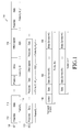
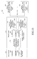
- FIG. 1 illustrates a generic frame structure for provision of transport streams of data according to the related art.
- a frame structure 100 illustrates data services 102 and 104 generally arranged in transport streams, e.g., a stream of data packets 106, for delivery over a target DVB system.
- transport streams e.g., a stream of data packets 106
- One goal in designing a multimedia data structure, such as in DVB-NGH is to organize efficiently and flexibly the delivery of the transport streams within the physical resources of the DVB system.
- Each transmitted frame (and therefore the subsequently received frame) 118 typically comprises a preamble section 112 and a data section 114, both of which are time-multiplexed.
- the transmitted received frames 118 are sent on two radio frequencies, RF1 108, RF2 110 in this simple illustration.
- the data section 114 may carry data that is arranged in the form of a number of data streams that may be referred to as PLP.
- a PLP may carry, for example, a service, such as a video channel provided to a user. Reception of data decoded from the received frames may be assisted by use of signaling fields/data/bits, and the like, which may typically be carried in the preamble section 112 of the frame.
- the signaling is often referred to as physical layer signaling, or L1 signaling.
- the signaling may indicate a modulation or coding scheme to be used for decoding data, and it may for example indicate sections of a data field to be decoded, or the location of a data stream within the data section.
- DVB frame structures may provide physical slots within the DVB physical frame structure, which are reserved in a standard for future use, for example referred to as Future Extension Frame (FEF) slots 116, which are time multiplexed with a given DVB-T2 signal.
- FEF slots 116 may be provided for transmission of signals intended for reception by mobile DVB receivers in addition to transmission of signals intended for reception by fixed DVB receivers of the related art.
- DVB systems may provide for the transmission of signals specifically intended for reception by hand held devices, such as NGH receivers.
- signals may be, for example, of lower bandwidth and have more robust modulation and coding than signals intended for reception by fixed receivers.
- DVB-T2 DVB-T2
- FEF slots additional physical slots
- a frame for the transmission of a signal intended for reception by a handheld receiver would be transmitted within the additional physical slot of a sequence of frames for the transmission of a signal intended for fixed receivers, including signaling information for the frame, which would be typically transmitted as a preamble in each FEF slot 116.
- a method of transmitting data in a wireless communication system comprising: mapping service data onto a first set of multiple Physical Layer Pipes (PLPs); mapping the first set of multiple PLPs onto a first set of logical frames, wherein each of the first set of logical frames is of the same size; forming a first logical channel comprising the first set of logical frames; and transmitting the mapped service data over a target delivery system.
- PLPs Physical Layer Pipes
- a network gateway comprising a processor arranged to: map service data onto a first set of multiple Physical Layer Pipes (PLPs); map the first set of multiple PLPs onto a first set of logical frames, wherein each of the first set of logical frames is of the same size; form a first logical channel comprising the first set of logical frames; and transmit the mapped service data over a target delivery system.
- PLPs Physical Layer Pipes
- FIG. 1 illustrates a generic frame structure for provision of transport streams of data according to the related art
- FIG. 2 is a schematic diagram of a data frame according to an exemplary embodiment of the present invention.
- FIG. 3A is a schematic diagram of a frame structure according to an exemplary embodiment of the present invention.
- FIG. 3B illustrates a table of data carried in Layer 1-Configuration (L1-Config) signaling portion of a frame according to an exemplary embodiment of the present invention
- FIG. 4 is a flow diagram of a process for arranging different types of configuration data items according to a first exemplary embodiment of the present invention
- FIG. 5A is a flow diagram of processes performed by a transmission apparatus when transmitting data according to the first exemplary embodiment of the present invention
- FIG. 5B is a flow diagram of processes performed by a receiver when receiving data according to the first exemplary embodiment of the present invention.
- FIG. 6A is a schematic diagram of a first exemplary arrangement of data configuration items in a sequence of frames according to a second exemplary embodiment of the present invention.
- FIG. 6B is a schematic diagram of a second exemplary arrangement of data configuration items in a sequence of frames according to the first exemplary embodiment of the present invention.
- FIG. 7 is a flow diagram of a process for arranging configuration data items in different types according to the second exemplary embodiment of the present invention.
- FIG. 8A is a flow diagram of processes performed by a transmission apparatus when transmitting data according to the second exemplary embodiment of the present invention.
- FIG. 8B is a flow diagram of processes performed by a receiver when receiving data according to the second exemplary embodiment of the present invention.
- FIG. 9 is a schematic diagram of a third exemplary arrangement of data configuration items arranged in a frame sequence according to an exemplary embodiment of the present invention.
- FIG. 10 is a schematic diagram of data carried in a frame structure being decoded according to an exemplary embodiment of the present invention.
- FIG. 11 is a schematic diagram of a system according to an exemplary embodiment of the present invention.
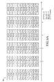
- FIG. 12 is a table of data carried in an L1-Config signaling portion of a frame according to an exemplary embodiment of the present invention.
- FIGs. 13A and 13B illustrate a table of data carried in an L1-Config signaling portion of a frame according to an exemplary embodiment of the present invention
- FIG. 14A is a schematic diagram of an exemplary arrangement of data configuration items in a sequence of frames according to an exemplary embodiment of the present invention
- FIG. 14B is a schematic diagram of an exemplary arrangement of data configuration items in a sequence of frames according to an exemplary embodiment of the present invention.
- FIG. 15 illustrates an overview of some elements of a Digital Video Broadcasting (DVB) system adapted according to an exemplary embodiment of the present invention
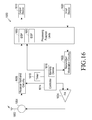
- FIG. 16 illustrates a block diagram of a receiver wireless communication unit according to an exemplary embodiment of the present invention
- FIG. 17 illustrates a logical frame structure according to an exemplary embodiment of the present invention
- FIG. 18 illustrates a mechanism for mapping Physical Layer Pipes (PLPs) in a logical frame structure according to an exemplary embodiment of the present invention
- FIG. 19 illustrates a mechanism for mapping PLPs in a logical frame structure with identified frame types according to an exemplary embodiment of the present invention
- FIG. 20 illustrates a mechanism for incorporating an input stream synchronization field in a logical frame structure according to an exemplary embodiment of the present invention
- FIG. 21 illustrates a logical super-frame structure according to an exemplary embodiment of the present invention
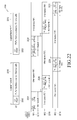
- FIG. 22 illustrates a logical channel structure comprising a sequence of logical frames according to an exemplary embodiment of the present invention
- FIG. 23 illustrates a logical channel Type-A structure comprising a sequence of logical frames according to an exemplary embodiment of the present invention
- FIG. 24 illustrates a logical channel Type-B structure comprising a sequence of logical frames according to an exemplary embodiment of the present invention
- FIG. 25 illustrates a logical channel Type-C structure comprising a sequence of logical frames according to an exemplary embodiment of the present invention
- FIG. 26 illustrates a logical channel Type-D structure comprising a sequence of logical frames according to an exemplary embodiment of the present invention
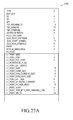
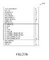
- FIG. 27 illustrates a table of an L1-Pre signaling field in a logical channel structure according to an exemplary embodiment of the present invention
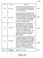
- FIG. 28 illustrates a table of an L1-Pre signaling format for a logical channel type according to an exemplary embodiment of the present invention
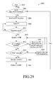
- FIG. 29 illustrates a flowchart of an initial scanning operation of a receiver receiving a logical channel according to an exemplary embodiment of the present invention
- FIG. 30 illustrates a flowchart of a normal continuous reception operation of a receiver receiving a logical channel according to an exemplary embodiment of the present invention
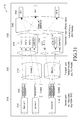
- FIG. 31 illustrates an overview of stages for a transport of data services in a delivery system according to an exemplary embodiment of the present invention.
- FIG. 32 illustrates a computing system that may be employed to implement signal processing functionality according to an exemplary embodiment of the present invention.
- DVD-NGH Digital Video Broadcasting-Next Generation Handheld
- data is transmitted using Orthogonal Frequency Division Multiplexing (OFDM).
- OFDM Orthogonal Frequency Division Multiplexing
- PLPs Physical Layer Pipes
- PLPs Physical Layer Pipes
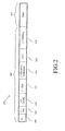
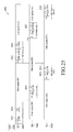
- FIG. 2 is a schematic diagram of a data frame according to an exemplary embodiment of the present invention.
- a data frame 200 comprises a preamble section 202 and a data section 204.
- the preamble section 202 comprises signaling portions "P1" 206, "L1-pre” 208, “L1-Config” 210, “L1-Dyn” 212, “L1-Dynamic Extension” 214 and a Cyclic Redundancy Check (CRC) 216 and "L1 Padding" 218.
- the data section carries payload data, such as data transmitted in PLPs.
- the data section 204 also includes multiple portions for transmitting different types of payload data.
- the P1 signaling portion 206 contains data identifying the preamble.
- the L1-Pre signaling portion 208 typically contains signaling information relating at least to the modulation and coding scheme needed to receive the remainder of the preamble.
- the L1-Config signaling portion 210 carries information that is valid for each frame 200 of a given superframe, and is typically the same for each frame of the superframe.
- the information carried by the L1-Config signaling portion 210 includes configuration data, such as data items indicating a number of PLPs carried within the superframe, or the modulation type used by an associated PLP. Further examples of the configuration data items carried in the L1-Config part 210 are described below.
- the term "configuration data item" as used herein may refer, for example, to all configuration data included in the signaling part of a given frame relating to a given PLP, or it may refer to a part of such data.
- the L1-Dyn signaling portion 212 carries information that varies from frame to frame, and relates to decoding the PLPs within the frame 200.
- the L1-Dyn signaling portion 212 may include an index of the frame 200 within the superframe and or a start address of a PLP.
- the L1-Dynamic Extension signaling portion 214 allows for the inclusion of further signaling information not included in the other portions.
- the CRC part 216 includes CRC-codes for the detection of transmission errors at the receiver.
- the L1 Padding part 218 is a variable-length field and is inserted following the CRC field to ensure that multiple Low Density Parity Check (LDPC) blocks of the L1-post signaling (i.e., the parts subsequent to the Pre signaling portion 208) have the same information size when the L1-post signaling is segmented into multiple blocks and these blocks are separately encoded.
- LDPC Low Density Parity Check
- Different signaling portions of the preamble 202 may be encoded together or separately for transmission.
- the L1-Config signaling portion 210 may be coded together with, or separate from, the L1-Dyn signaling portion 212.
- the data section 204 carries data arranged in PLPs. However, it will be understood that each PLP is not necessarily mapped to every frame 200.
- different repetition lengths are set for different types of configuration data item so that different types of configuration item are repeated according to different lengths within a frame structure comprising multiple frames.
- FIG. 3A is a schematic diagram of a frame structure according to an exemplary embodiment of the present invention.
- a frame structure 300 comprises n frames in which different configuration data items P nm are transmitted in each frame of the frame structure 300.
- FIG. 3A shows data included in the L1-Config signaling portion 210 of each frame and the other parts of the frames are omitted for conciseness.
- the data included in the L1-Config signaling portion 210 comprises constant data 302 and configuration data 304.
- the constant data 302 comprises configuration information which is independent of any particular PLP.
- the constant data 302 comprises signaling information items, such as Time Frequency Slicing (TFS) items, Future Extension Frame (FEF) signaling information items and/or auxiliary streams information items, which are required to be transmitted in each frame.
- TFS Time Frequency Slicing
- FEF Future Extension Frame
- the configuration data 304 includes configuration data items which each relate to one or more PLPs, and are for use in receiving the one or more PLPs to which they relate.
- the configuration data items are separated into different types 304a...304N, with different repetition lengths being set for each of the different types of configuration data item.
- P nm indicates configuration data items having a repetition length n such that they are repeated every n frames, and which are first transmitted in frame m.
- the frames may also include additional data, such as dummy data relating to dummy PLPs. Such data may also be assigned a repetition length, as is described below.
- configuration data items P 11 are repeated in every frame
- configuration data items P 21 are repeated in frames 1, 3, 5...
- configuration data items P 22 are repeated in frames 2, 4, 6..., and so on.
- the lowest repetition length set is that for the configuration data items P Nm which are repeated every n frames.
- the repetition length n thus defines a number of frames (n-1) which sequentially follow in the frame structure before a type of configuration data item having a repetition length n is repeated.
- each configuration data item is included at least once in the frame structure 300.
- less data is required to be transmitted during each frame, resulting in a saving in terms of signaling overhead compared to prior art methods in which all configuration data items are transmitted in every frame.
- the delay in decoding which occurs at the receiver at, for example, initialization or in the event of changing channels can be controlled according to, for example, the service requirements of the PLP to which a given configuration data item relates (the average delay in receiving a configuration data item which is repeated every n frames being n/2 times the length of each frame).
- configuration data items relating to PLPs for which a long delay is undesirable may be allocated a lower repetition length than configuration data items relating to PLPs for which a delay may be tolerable.
- the basis version of the service may use a Single-Input and Single-Output (SISO) configuration, with the enhanced version using a Multiple-Input and Multiple-Output (MIMO) configuration of the same service.
- SISO Single-Input and Single-Output
- MIMO Multiple-Input and Multiple-Output
- configuration data items for receiving the base layer of the scheme may be transmitted at a higher repetition length than the configuration data items for receiving the enhanced layer of the scheme.
- the receiver may initially decode the base stream and display the transmission to the user, immediately after the configuration data items for the base layer have been received, without having to wait for those relating to the enhanced layer.
- the frame structure 300 shown in FIG. 3A includes only N frames (a number equal to the longest repetition length for the transmission), it will be appreciated that there is no limit to the length of a frame structure according to which data is transmitted.
- the length of the frame structure may be equal to the lowest common multiplier of all frame repetition lengths.
- the frames of the frame structure may be arranged into superframes.
- the maximum repetition length, or maximum cycle length, set for the transmission may be selected such that the length of a superframe is equal to, or a multiple of, N.
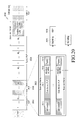
- FIG. 3B illustrates a table of data carried in an L1-Config signaling portion of a frame according to an exemplary embodiment of the present invention.
- the table includes constant data 302 and configuration data 304, along with exemplary corresponding data sizes, included in the L1-Config signaling portion 210 of a frame.
- the constant data 302 includes the data item "Num_PLP_config” 302a which indicates the number of PLPs for which configuration data 304 is included in each frame.
- the configuration data 304 includes various configuration data items. It should be understood that the term “configuration data items" may relate to either data included in a single field within the configuration data, or to data included in a set of related fields. In this exemplary embodiment, an identifier of the PLP is identified in the configuration data item "PLP_ID" 306.
- the configuration data item "L1Config_Repetition_Length” 308 indicates the repetition length of the configuration data items relating to the PLP identified. Although shown as a new field here, the "L1Config_Repetition_Length" 308 is included in an extension field, such as "Reserved_1" field.
- the configuration data items are ordered for transmission based on their repetition length, so that configuration data items having a lower repetition length are transmitted before those having a higher repetition length.
- Configuration data items having the same repetition length may further be ordered so that they are transmitted in order of the PLP_ID 306 of the PLP to which they relate.
- the configuration data items may be arranged in ascending order.
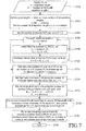
- FIG. 4 is a flow diagram of a process for arranging different types of configuration data items according to an exemplary embodiment of the present invention.
- a set (referred to herein as S n ) of a number Qn of unallocated PLPs having a desired repetition length of n is determined.
- the desired repetition length may be determined based on the identification of a service requirement, set by a network operator for example, in relation to each of the PLP.
- step S402 it is determined whether Q n is equal to or a multiple of n (e.g., if n is 4, it is determined whether Q N is 4, 8, 12..., or whether it is a number which is not a multiple of 4). If it is determined that Q n is not equal to n, or a multiple thereof, configuration data for a PLP having a desired repetition length of n+1 is added to the set S n , so that the value of Q n increases by 1 at step S404. This step is performed based on the observation that the service for PLP requiring a repetition length of n+1 suffers from no degradation, and in fact is improved, by reduction the repetition length to n. After step S404, the process returns to step S402, and steps S402 and S404 are repeated until the value of Q n is determined to be equal to or a multiple of n.
- the number P n of PLPs for which corresponding configuration data items are transmitted at a repetition length n is set at Q n at step S406.
- the configuration data items included in S n once the condition that Q n is equal to or a multiple of n is satisfied are categorized as being of a type having a repetition length n, with S 1 , S 2 , S 3 , and S N corresponding respectively to data types 204a, 204b, 204c and 204 N described above in reference to FIG. 2 .
- step S408 the configuration data items included in S n are further categorized into n groups P n1 ...P nn , corresponding to the data items P nm described above in relation to FIG. 2 .
- the P nm for any given value of n are selected to include configuration data items relating to the same number of PLPs irrespective of the value of m.
- step S410 it is determined whether there are any PLPs for which the corresponding configuration data items have not yet been allocated (i.e., for which no repetition length has been set) during the process of FIG. 4 . If it is determined that there are configuration data items that have not yet been allocated, the value of n is incremented at step S412 and the process returns to step S400 and repeats using the incremented value of n. If there are no further configuration data items to be allocated, the process proceeds to step S414 where transmission of the data in accordance with the frames arranged in the preceding steps is initiated.
- configuration data items for all PLPs are categorized into different types having a repetition length which is set at a value equal to or less than a desired repetition length determined based on a service requirement associated with the PLP, ensuring that the quality of service is maintained at or above the desired level.
- the number of PLPs having a repetition length less than the desired length is kept to a minimum, the saving in signaling overhead achieved by not repeating all configuration data items in each frame can be maximized.
- step S404 it was assumed at step S404 that there existed a PLP having desired repetition length of n+1.
- configuration data items for a PLPs having a desired repetition of more than n+1 may be used. If the configuration data for all PLPs has already been allocated (i.e., if n is at the maximum value for the PLPs being transmitted), dummy configuration data items relating to dummy PLPs may instead be used. Additionally or alternatively, configuration data relating to one or more already allocated PLPs may be repeated, to ensure that Q n is equal to or a multiple of n.
- each type of configuration data item into n groups such that each group of a given type relates to the same number of PLPs it can be ensured that each of the frames in the frame structure have a constant number of data items i.e., that the signaling capacity for each frame remains constant. This has the advantage that it simplifies scheduling.
- Table 1 shows a pseudo-code for an algorithm for arranging the configuration data items in a similar manner to that described with reference to FIG. 4 .
- FIG. 5A is a flow diagram of processes performed by a transmission apparatus when transmitting data according to the first exemplary embodiment of the present invention.
- step S500 configuration data items, which may be in the form of raw L1-Config signaling data, are generated.
- the transmission apparatus determines whether partitioning is enabled i.e., whether a transmission method in accordance with the first exemplary transmission method is to be used. If the determination is that such a transmission method is not to be used, the process proceeds to step S504 where the configuration data items are scheduled for transmission in every frame, per methods of the related art.
- the configuration data items are built into frames of the frame structure (cycle) by a frame builder of the transmission apparatus at step S506, and subsequently transmitted.
- step S502 determines whether a method according to the first exemplary transmission method is to be performed. If the determination at step S502 is that a method according to the first exemplary transmission method is to be performed, the process proceeds to step S508, where the transmission apparatus determines a repetition length for each PLP to be transmitted. This may be performed according to a method as described above with reference to FIG. 4 .
- the transmission apparatus schedules the configuration data items for each PLP.
- the transmission apparatus arranges the configuration data items over a cycle, as illustrated in FIG. 2 .
- the configuration data items are built into frames of the cycle by a frame builder of the transmission apparatus at step S516, and subsequently transmitted.
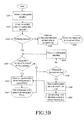
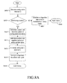
- FIG. 5B is a flow diagram of processes performed by a receiver when receiving data according to the first exemplary transmission method.
- the process starts at step S520 where the receiver apparatus decodes the L1 configurable signaling received in a first frame of the first cycle of the superframe by which it receives data.
- the constant data 202 of the frame is extracted.
- the receiver apparatus determines whether partitioning is enabled i.e., whether a transmission method in accordance with the first exemplary transmission method is in use. If the determination is that such a transmission method is not being used, the receiver apparatus determines that the configuration data items corresponding to each PLP are being transmitted in every frame of the cycle. Accordingly, the receiver apparatus proceeds to step S526 and extracts configuration data items corresponding to one or more desired PLP i.e., the one or more PLPs corresponding to the service in relation to which the receiver apparatus is to receive data. The receiver apparatus proceeds to step S528 in which the extracted configuration data items are used to decode the data transmitted in the desired one or more PLPs. The receiver apparatus proceeds to step S526 where the configuration data items are scheduled for transmission in every frame, per methods of the related art. The configuration data items are built into frames of the cycle by a frame builder of the transmission apparatus at step S506, and subsequently transmitted.
- step S524 determines whether partitioning is enabled. If the determination at step S524 is that partitioning is enabled, the process proceeds to step S530 where it is determined whether the configuration data items for the desired one or more PLPs are available in the frame currently being processed. If the determination is that the relevant configuration data items are not available, the process proceeds to step S536, described below.
- step S532 the configuration data items corresponding to the desired one or more PLPs are extracted.
- the extracted configuration data items are used to decode the one or more desired PLPs, at step S534.
- step S536 it is determined whether all frames in the first cycle of the superframe have been received. If the determination is that not all frames in the cycle have been received, the receiver apparatus decodes the L1 configurable data received in the next frame of the cycle, at step S538.
- the process returns to step S530 described above. Steps S530 to S538 may be repeated iteratively for all frames in the cycle, or until all required configuration data items have been extracted.
- the receiver apparatus stores the repetition pattern and position within the cycle of the configuration data items required for the desired PLPs at step S540. This enables the receiver apparatus to predict the position within the cycle at which it will subsequently receive the configuration data items which, in combination with the fact that the same pattern of configuration data items is repeated in each cycle, may reduce the error rate of the receiver. As indicated at step S542, the receiver apparatus need only extract configuration data items from the frames in which the desired configuration data items are predicted to be positioned. This reduces the processing load on the receiver apparatus, and may also enable the receiver apparatus to save power by entering a low power mode, such as a sleep mode, in parts of the cycle in which it is not required to receive data.
- a low power mode such as a sleep mode
- one or more configuration data items are allocated repetition lengths shorter than the desired repetition length.
- all configuration data items are allocated repetition lengths equal to the desired repetition length, irrespective of whether Q n is equal to n, or a multiple integer thereof. This may be done by varying the number of PLPs corresponding to a given repetition length from frame to frame, whilst maintaining constant the total number of PLPs per frame, as is now described.
- the frames are arranged in groups, or cycles, each containing a number of frames equal to the total lowest common multiplier (L) of all the desired repetition lengths.
- the configuration data items are included in data slots (referred to herein as configuration data slots) of the L1-Config signaling portion 110 of each frame.
- Each configuration data item having a repetition length n is included L/n times in each cycle, with each cycle being repeated during transmission.
- one or more additional data items can be added into additional data slots (referred to herein as additional data slots) so that the total number of PLPs (including the dummy PLPs), and the number of corresponding data slots (i.e., the sum of the configuration data slots and the additional data slots), is constant across the frame cycle (and is typically constant across multiple frame cycles).
- additional data slots i.e., their locations within frames and within the cycle of frames
- these features may reduce the error rate of the receiver, and may enable the processing load on the receiver apparatus to be reduced, and/or enable the receiver apparatus to save power.
- FIG. 6A is a schematic diagram of a first exemplary arrangement of data configuration items in a sequence of frames according to a second exemplary embodiment of the present invention.
- the arrangement of data configuration items has different repetition lengths in a cycle 600 of frames.
- the data slots are shown by type (i.e., configuration data slot and additional (dummy) data slot), and according to the repetition length n associated with the data included in the data slot.
- the PLP index of the PLP to which the data included in the data slots relates is also indicated.
- FIG. 6B is a schematic diagram of a second exemplary arrangement of data configuration items in a sequence of frames according to the first exemplary embodiment of the present invention.
- This exemplary method provides many of the same advantages that are provided by the first exemplary transmission method described above. More particularly, the overhead savings are the same. This is illustrated by the example of FIG. 6A and 6B , in which, in each case, configuration data items corresponding to twelve PLPs are included in each frame (including a dummy PLP in the sixth frame of FIG. 6A ).
- the repetition length may be a fixed attribute of the corresponding PLP. Therefore, the present method avoids any desirable alteration of this fixed attribute.
- the configuration data items repeated according to this pattern can be maintained in the cluster of configuration data items having the desired repetition length, and it is not necessary to alter the attribute "repetition length" associated with the configuration data items.
- the receiver of the transmission can be arranged to anticipate the pattern of configuration data items shown in FIG. 6A .
- additional space is made available in the frame, in the form of additional data items corresponding to the dummy PLPs, which may be used for transmitting "extra" data.
- a particular value may be assigned to an identifier in the frames including the additional data items, to identify the additional data items as such.
- the receiver may either discard the additional data items, if they are "dummy" data items not being used to transmit extra data, or else process the additional data items if they are being used to transmit extra data.
- the PLP identifier whose value may identify additional data items may be included as a configuration data item in the L1-Config signaling portion 110 of the frame.
- the receiver apparatus may not require a particular value to identify the presence of the additional data items and may only require knowledge of the position within the cycle.
- FIG. 7 An exemplary method of providing an arrangement of configuration data items and additional data items according to the second exemplary transmission method is now described with reference to FIG. 7 .
- FIG. 7 By way of illustration, how the process of FIG. 7 would be implemented with the same input parameters as FIG. 6A is also described below.
- FIG. 7 is a flow diagram of a process for arranging configuration data items in different types according to the second exemplary embodiment of the present invention.
- step S700 the input parameters are received, namely the number P n of PLPs having repetition length n.
- the number D of additional data slots (e.g., the number of dummy PLPs) per cycle is set at an initial value of zero.
- Step S706 starts an iterative procedure, in which the value of D is iterated.
- Steps S708 to S710 are iterated to obtain a total value for D, summed over all values of n greater than 1.
- n n greater than 1.
- the value of A l,n represents the number of data slots assigned to repetition length n of the 1 th frame of the candidate cycle.
- matrix B representing an initial distribution of additional data slots (dummy PLPs) amongst the frames of the cycle is defined having size L x N, with elements B l,n , where:
- the value of B l,n represents the number of additional data slots assigned to repetition length n of the 1 th frame of the candidate cycle.
- the process proceeds to reduce the number of additional data slots reduced from the candidate cycle. As described above, a number of additional data slots equal to E is removed from each frame of the candidate cycle. This is done in two-step process, as is described below.
- step S7108 for each frame of the candidate matrix having a number of additional data items greater than or equal to E, a number of frames equal to E can simply be removed.
- step S720 configuration data items corresponding to a number of configuration data slots equal to E are removed from each frame from which it was not possible to remove E additional data slots, to one or more frames including additional data slots. A corresponding number of additional data items is removed from the frames to which the configuration data items are moved.
- these matrices correspond to the arrangement shown in FIG. 6A .
- an additional (e.g., dummy) data slot has been included in the final frame of the cycle, it should be noted that this is not always the case.
- additional data slots may be included at other locations within the cycle.
- step S720 After completion of the "swapping" procedure of step S720, the process ends at step S722.
- Cycles generated according to the above process can be used for transmitting signaling data, by repeating the cycle during the transmission of data.
- the process described above with reference to FIG. 7 is by way of example only, and the various steps described may vary.
- FIG. 8A is a flow diagram of processes performed by a transmission apparatus when transmitting data according to the second exemplary embodiment of the present invention.
- steps S800 to S806 correspond, respectively, to steps S500 to S506 described above in relation to FIG. 5A .
- the step corresponding to step S508 may be omitted. This is because, as described above in the second exemplary transmission method, all configuration data items are assigned the corresponding desired repetition length. Instead the process proceeds to step S810, where the transmission apparatus determines a position within the cycle, and a repetition pattern for each PLP to be transmitted. Step S810 corresponds to step S510 described above.
- step S811 the transmission apparatus determines the position and repetition pattern for any such additional data items to be included in the cycle (cycle).
- Subsequent processing steps S812 to S816 correspond, respectively, to processing steps S512 to S516 described above in relation to FIG. 5A .
- FIG. 8B is a flow diagram of processes performed by a receiver when receiving data according to the second exemplary embodiment of the present invention.
- steps S820 to S834 correspond, respectively, to steps S520 to S534 as described above in relation to FIG. 5B .
- step S830 if it is determined at step S830 that there are no configuration data items for the desired one or more PLPs in the frame currently being processed, or after decoding the desired one or more PLPs at step S834, the receiver apparatus proceeds to determining whether any additional data signaling, containing additional data items as described above, is available for the currently processed claim. If such data signaling is available, the additional data items included therein are extracted and used at step S844. The process proceeds to step S836, which corresponds to step S536 described above in relation to FIG. 5B . Subsequent steps S838 to S842 correspond, respectively, to steps S538 to S542 described above in relation to FIG. 5B .
- step S835 If the determination at step S835 is that additional data signaling is not available, the receiver apparatus proceeds directly to step S836, without performing step S844.
- all required configuration data items relating to an integral number of PLPs may be included in each frame. This enables the data relating to a given PLP carried in an L1-Config signaling portion 110 of a given frame to be self-decodable, as described below.
- the size of the part of the L1-signaling portion which is allocated to configuration data items of a given repetition length is determined by the number of data slots included in the relevant part, the data slots being occupied by configuration data items corresponding to actual PLPs, or dummy data corresponding to dummy PLPs.
- data configuration items may be divided across multiple frames of a sequence, with the bit size of each part of the frame that is allocated to a configuration data item having a given repetition length being kept at a constant length for each of a sequence of frames.
- the sum total (T) of the bit sizes of the configuration data items having repetition length n is determined and divided by n. For each value of n, an amount of data equal to T/n is allocated to each frame of the sequence.
- additional "dummy" data for example one or more zeros, may be included in the relevant part one or more of the frames of the sequence, so that the part of the frame allocated to a given value of n remains constant across the sequence of frames.
- FIG. 9 is a schematic diagram of a third exemplary arrangement of data configuration items arranged in a frame sequence according to an exemplary embodiment of the present invention.
- the constant part (containing the constant data 302) of the L1-Config signaling portion of the frames of the sequence may include an indicator of the bit size of each of the above-described parts 210a, 210b, and 210c of the L1-Config signaling portion 210, as well as an indicator of the number of zeros (if any) included in the corresponding part.
- the L1-Pre portion 208 may include an indicator of the bit size of the constant portion of one or more frames of the sequence.
- the zeros (or other dummy data) may be included at another predefined position in the sequence. By including the dummy data at a predefined position in a sequence, processing on receipt of the transmitted data is simplified, since the receiver may simply discard the indicated number of zeros prior to processing the configuration data items.
- the third exemplary transmission method allows an even greater saving in transmission overhead than the first and second exemplary transmission methods. This is because, in the present exemplary method, it is neither necessary to allocate a repetition length greater than a desired repetition length (as is sometimes the case in the first exemplary transmission method), nor is it necessary to add any additional data items corresponding to dummy PLPs (as is sometimes the case in the second exemplary transmission method).
- the transmission apparatus may include an input communications interface for receiving data streams, for example different digital video broadcast channels, to be encoded into a frame structure, a processor, or set of processors, for performing processing steps in conjunction, where appropriate, with a data storage device, which may store data, such as the desired repetition lengths described above.
- the transmission apparatus typically also includes an output communications interface for wirelessly transmitting data.
- the data transmitted by the transmission apparatus is typically received by one or more receiver apparatuses, each comprising an input communications interface for wirelessly receiving the data, a processor, or set of processors, for performing, in conjunction with a data storage means where appropriate, processing of the received signal as is now described, and a video display, an audio transmitter and/or an output communications interface for outputting one or more selected decoded data streams.
- receiver apparatuses each comprising an input communications interface for wirelessly receiving the data, a processor, or set of processors, for performing, in conjunction with a data storage means where appropriate, processing of the received signal as is now described, and a video display, an audio transmitter and/or an output communications interface for outputting one or more selected decoded data streams.
- the receiver apparatus On receipt of the data transmitted in a frame structure as described above, the receiver apparatus selects different PLPs to be received, the different PLPs corresponding to different repetition lengths, for example in response to a change of channel at the receiver apparatus.
- the receiver apparatus receives configuration data items corresponding to each selected PLP, and receives the corresponding PLP using the received corresponding configuration data items.
- one or more received frames may include a dummy PLP identifier, as described above.
- the receiver apparatus may parse the PLP identifier, identify the additional data to which it relates and process the additional data accordingly. In some cases, this may involve simply discarding the additional data.
- the additional data may include extra data, which the receiver apparatus may be configured to receive and process, on receipt of an identifier value indicating that such extra data is carried.
- the L1-Config signaling portion 210 may be divided into different parts 210a, 210b, and 210c, associated with different repetition lengths.
- At least one frame of the frame structure may include one or more indicators of these lengths, which the receiver apparatus may be arranged to receive. On receipt of same, the receiver apparatus may identify the length of each of the parts 210a, 210b, and 210c from corresponding indicators, and process the data in the different parts accordingly.
- one or more of the frames of the frame structure may include dummy values, such as a sequence of zeros, for example at the end of the L1-Config signaling portion 210 of one or more of the frames.
- one or more frames of the frame structure may include an indicator of the number of zeros, so that they can be discarded by the receiver apparatus.
- the data relating to a given PLP carried in an L1-Config signaling portion 210 of a given frame may be self-decodable i.e., contain all data necessary for decoding to commence, so that decoding in relation to a given PLP can be started as soon as the corresponding configuration data items are received. Furthermore, once a first instance of a given configuration data item has been received and decoded, and since the configuration data items are ordered in a predictable way, based on the repetition length and/or PLP identifier as described above, it may be unnecessary to decode subsequent instances of the same configuration data item.
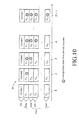
- FIG. 10 is a schematic diagram of data carried in a frame structure being decoded according to an exemplary embodiment of the present invention.
- a frame structure 200 comprises n frames in which different configuration data items P nm are transmitted in each frame of the frame structure 200.
- the frame structure 200 is similar to the frame structure 300 of FIG. 3A . Assuming that each configuration data item is decoded correctly the first time an instance thereof is received, all configuration data items are decoded after N+1 frames, where N is the longest repetition length set for the transmission.
- the first time an instance of a configuration data item is received and decoded it may be stored in a data storage means of the receiver apparatus with the stored instance being used to identify and receive the corresponding PLP in subsequent frames. Subsequent, repeated, instances of the same configuration data item within a superframe may be flagged by the receiver to be ignored by the decoder and not decoded.
- the stored instance can be used to identify and receive the corresponding PLP in subsequent frames within the superfame, even those which follow the frames containing the repeated instances of the configuration data time.
- each instance of any given configuration data item transmitted in the frame structure 300 may be decoded, to maintain simplicity of receiver operation and/or to reduce decoding errors.
- a receiver sets one or more values associated with a soft decoder to one or more predefined values, to indicate that the configuration data item is already identified.
- LLRs Log Likelihood Ratios
- the LLRs for the further, repeated, instances of the configuration data items may be set in the remainder of the superframe to +/- ⁇ , to indicate that these have already been identified.
- the identified configuration data items can be used to facilitate the decoding of other data, such as other data carried in the L1-Config signaling portion 210 and/or data contained in the L1-Dyn signaling portion 212.
- Other data such as other data carried in the L1-Config signaling portion 210 and/or data contained in the L1-Dyn signaling portion 212.
- the fact that some bits in the received data are already identified increases the robustness of decoding, in terms of error correction, of other bits in the received data.
- the decoded data can be used to facilitate in a decoding process of further sets of data including the configuration data item.
- the fact that the bits of the configuration data item are identified improves the robustness of error correction in relation further data items included in the further sets of data.
- These further data items may comprise data items carried in an L1-Config signaling portion 210 of a frame, or another signaling portion, such as an L1-Dyn signaling portion 212, where the latter is coded together the L1-Config signaling portion 210.
- the configuration data may vary from superframe to superframe. Accordingly, in some exemplary embodiments, the receiver apparatus decodes at least the first instance of each configuration data item in each superframe. However, since the configuration data items may change only infrequently, even between different superframes, in some exemplary embodiments the receiver apparatus does not decode the first instance of each configuration data item in each superframe. Instead, an indication may be included in, for example, the L1-Dyn signaling portion 212 indicating that the configuration data items has changed, and the receiver apparatus decodes new instances of configuration data in response to receiving this indication. The indication may indicate one or more PLPs whose corresponding configuration data items have changed. In this case, the receiver apparatus may newly decode configuration data items for only the PLPs indicated.
- the exemplary methods of data transmission described herein may be performed by a network operator in accordance with the requirements of a service provider.
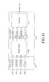
- FIG. 11 is a schematic diagram of a system according to an exemplary embodiment of the present invention.
- the system includes a service provider 1100 and a network operator 1102.
- the service provider 1100 provides data relating to one or more services 1104 to the network operator 1102, along with control data 1106, which may include service requirements, such as a desired repetition length, or data from which a desired repetition length can be derived, such as a delay tolerance, and the like.
- the network operator 1102 receives data from the service provider at a network gateway 1108.
- the network gateway 1108 additionally performs functions, such as mapping service requirements onto PLPs and their service attributes, such as repetition length.
- the network gateway 1108 sends data relating to each of one or more PLPs 1110, along with control data 1112 to a transmitter 1114.
- the control data 1112 may include PLP attributes, such as a repetition length, and the like.
- the transmitter 1114 may perform functions, such as generation of signaling, frame building, and transmission of data.
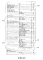
- FIG. 12 is a table of data carried in an L1-Config signaling portion of a frame according to an exemplary embodiment of the present invention. More specifically, FIG. 12 shows an alternative arrangement for the constant data 302 and configuration data 304 included in the L1-Config signaling portion 210 of a frame. The table of FIG. 12 is similar to the table of FIG. 3B .
- the number of PLP configurations is limited to a number lower than the number of PLPs in use, and the PLPs are classified according to the PLP configuration ("PLP mode") used.
- PLP mode the PLP configuration
- the configuration data items common to a given PLP mode need not be separately transmitted for each PLP of the given PLP mode.
- the different types of configuration data item may be assigned on a PLP by PLP basis, as described above, or instead based on the different PLP modes.
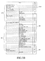
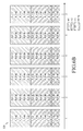
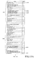
- FIGs. 13A and 13B illustrate a table of data carried in an L1-Config signaling portion of a frame according to an exemplary embodiment of the present invention.
- the constant data in the example of FIG. 13A includes an "options flag" data item 1300, which indicates whether a given option with related signaling in L1-CONF is used. If the given option is in use, the signaling fields associated with the option are signaled in L1-CONF. Otherwise, they are not included and this enables overhead reduction when the given option is not used.
- Table 2 provides an example of some different options that may be indicated by this field.
- Table 2 Value Option Enabled xxxxxxx1 Sub-slicing xxxxxx1x Auxiliary streams xxxxx1xx RESERVED_1 field inside the PLP loop xxxx1xxx RESERVED_2 field inside the PLP MODE loop xxx1xxxx RESERVED_3 field xx1xxxxx Partitioning of the PLP loop x1xxxxxx Reserved for future use 1xxxxxxx Reserved for future use
- xxlxxxxx indicates that a method of transmission of data in accordance with an exemplary embodiment of the present invention is to be performed. This corresponds with data item 1302 in FIG. 13A .
- the "PARTITION_CYCLE_LENGTH" data item 1304 indicates the length, in number of frames, of one cycle across which the signaling in the PLP loop of L1-CONF for all the PLPs in the current super-frame is complete.
- the signaling in the PLP loop of all PLPs in the current super-frame will generally be exactly the same.
- the signaling in the PLP loop of L1-CONF for each PLP repeats at the same frame position every L frames in the current super-frame, where L is the value given by PARTITION_CYCLE_LENGTH. This value stays constant in at least the current super-frame.
- the "PARTITION_NUM_ADD_PLP" data item 1306 indicates the number of additional signaling blocks added in the PLP loop of the current frame in order for each frame in the partition cycle to carry the signaling of an integer number of PLPs for each cluster of PLPs, as described below.
- the PLP_PARTITION_CLUSTER_ID data item 1308 indicates the partition cluster of the signaling in the PLP loop associated with the PLP identified by the PLP_ID.
- the partition cluster ID is defined in Table 3. Table 3 Value Description 00
- the signaling in the PLP loop associated with the given PLP tolerates 0 frame delay. It shall be carried in every frame of the current super-frame. 01
- the signaling in the PLP loop associated with the given PLP tolerates 1 frame delay. It may be carried in every 2nd frame of the current super-frame.
- the signaling in the PLP loop associated with the given PLP tolerates 2 frames delay. It may be carried in every 3rd frame of the current super-frame.
- the signaling in the PLP loop associated with the given PLP tolerates 3 frames delay. It may be carried in every 4th frame of the current super-frame.
- the signaling in the PLP loop of L1-CONF may be split into equal length partitions, so that each frame carries only one partition of the total signaling in the PLP loop.
- the L1-CONF data is arranged in two parts, a first part which contains all the signaling data in L1-CONF except for the PLP loop signaling, and a second part which contains the signaling in the PLP loop. Only the second part, i.e., the signaling in the PLP loop, may be subject to partitioning. The first part will always appear in every frame of the super-frame.
- a value of the field OPTIONS_FLAG equal to 'xx1xxxxx' indicates that partitioning of the PLP loop in L1-CONF is used.
- the frame may also carry an additional signaling associated with a number of dummy PLPs equal to PARTITION_NUM_ADD_PLP.
- the summation NUM_PLP_PER_FRAME + PARTITION_NUM_ADD_PLP shall be constant for every frame in the super-frame, in order to guarantee the same amount of L1-CONF signaling in every frame of the current super-frame.
- every PLP in the super-frame is assigned a partition cluster indicated by the field PLP_PARTITION_CLUSTER_ID.
- PLP_PARTITION_CLUSTER_ID is equal to "000"
- the signaling in the PLP loop associated with the given PLP shall be transmitted in every frame of the current super-frame, and hence does not tolerate any delay for its acquisition.
- PLP_PARTITION_CLUSTER_ID is equal to n (which is strictly greater than 0)
- the signaling in the PLP loop associated with the given PLP tolerates n frame delays, and hence may be transmitted every (n+1)-th frame in the super-frame.
- some of these PLPs may be assigned or re-assigned to a lower partition cluster value, and hence transmitted at a rate higher than the tolerable rate of every (n+1)-th frame in the super-frame, e.g., every n-th or (n-1)-th frame.
- all PLPs which tolerate n frame delays may be assigned to the same partition cluster n, and an additional signaling associated with a number of dummy PLPs equal to PARTITION_NUM_ADD_PLP may be added to some partition clusters (n > 0) in some frames in the current super-frame.
- This minimum number PARTITION_NUM_ADD_PLP can be determined from all the numbers of actual PLPs and their corresponding partition cluster values ⁇ n ⁇ over a period equal to the least common multiplier of all partition cluster values ⁇ n ⁇ .
- the additional signaling associated with the number PARTITION_NUM_ADD_PLP of dummy PLPs may be used for some purpose in the future.
- the signaling in the PLP loop of every frame l shall be associated with a constant number of PLPs, given by Q in Equation 1.
- P actual n l + P dummy n l Q
- the signaling in the PLP loop of L1-CONF for a given PLP will repeat at the same frame position every L frames in the current super-frame, where L is the value of the field PARTITION_CYCLE_LENGTH. From one cycle to another in the current super-frame, the signaling in the PLP loop of all PLPs in the current super-frame will be exactly the same.
- the partition cycle helps the receiver anticipate the pattern of appearance in the frames of the signaling in the PLP loop associated with the desired PLP. It also helps the receiver know when the full L1-CONF signaling repeats exactly in the current super-frame.
- the cycle length L is equal to the least common multiplier of all partition cluster values ⁇ n ⁇ .
- FIGs. 14A and 14B are schematic diagrams of an exemplary arrangement of data configuration items in a sequence of frames according to an exemplary embodiment of the present invention.
- the signaling of 1 PLP (PLP#1) will be repeated in every frame, whilst the signaling of 4 PLPs will be split into two partitions of 2 PLPs.
- the signaling of the first 2 PLPs (e.g., PLP#2, PLP#3) will be repeated in odd frames (e.g., 1, 3, 5, 7) whilst the signaling of the other two PLPs (i.e., PLP#4 and PLP#5) will be repeated in even frames (e.g., 2, 4, 6, 8). This is illustrated in FIG. 14A .
- every frame will have a PLP loop with a signaling amount equal to 5 x A, where A denotes the amount of signaling per PLP in the PLP loop. If partitioning is used, every frame will have a PLP loop with a signaling amount equal to 3 x A, in both alternatives.
- exemplary embodiments of the present invention will now be described in the context of a DVB-NGH system, in which, in one exemplary embodiment, additional data for reception by DVB-NGH receivers is transmitted within FEF slots currently contained within the 2 nd generation terrestrial DVB-T2 system.
- additional data for reception by DVB-NGH receivers is transmitted within FEF slots currently contained within the 2 nd generation terrestrial DVB-T2 system.
- the concepts herein described may be equally applied to a stand-alone DVB-NGH system that is not designed to 'piggy-back' on such an existing DVB-T2 system.
- the examples described herein are by way of example only, and that other exemplary embodiments may involve other wireless broadcast systems or unicast systems.
- alternative exemplary embodiments may be applied to other data transmission systems, and thus are not limited to the use for transmission of digital video signals.
- a physical frame/slot may, in some examples, be considered to be a duration in time on a given RF frequency where the signal corresponding to the target delivery system is present (transmitted).
- a FEF/additional slot may, in some examples, be considered to be a duration in time on a given RF frequency where the signal of the target delivery system is not present (not transmitted).
- a physical super-frame may, in some examples, be considered to be an entity including a number of physical frames and FEFs. The physical configuration may, in some examples, only change at the boundaries of two physical super-frames.
- a logical frame may, in some examples, be considered to be a conceptual container with a fixed number of Quadrature Amplitude Modulation (QAM) cells and a given structure for the carriage of data into the physical frames of the target delivery system.
- a logical super-frame may, in some examples, be considered to be an entity that includes a number of logical frames.
- the logical signaling information may in some examples only change at the boundaries of two logical super-frames.
- a logical channel may, in some examples, be considered to be a flow of logical frames all of substantially the same size and transmission properties for the carriage of data over the target delivery system.
- a logical channel group may, in some examples, be considered to be a group of logical channels such that the physical frames which carry the logical frames of one logical channel in the group are separable in time from the physical frames which carry the logical frames of another logical channel in the group (i.e., zero overlap in time).
- a transport stream may, in some examples, be considered to be a stream of data for an ensemble of services which are delivered to the end users by the delivery system (e.g., DVB-NGH).
- a transport stream may be structured by the delivery system into a number of logical channels defined in accordance with the services requirements.
- FIG. 15 illustrates an overview of some elements of a DVB system adapted according to an exemplary embodiment of the present invention.
- a DVB system 1200 includes a service provider 1202 that provides a plurality of services #1 ⁇ #M 1204 and a control channel 1206 that, in some examples, includes service requirement information.
- the service provider 1202 provides the services and control information to a broadcasting network operator 1210 via, say, a network gateway 1212.
- the network gateway 1212 may be arranged to provide mapping of service data and requirements onto PLPs and PLP service attributes, as shown.
- the mapping of service data may comprise mapping services and/or service components.
- the network gateway 1212 is operably coupled to a plurality of transmitters 1220 and 1222 via a plurality of PLPs #1 ⁇ #N 1214 and a control PLP 1216 that may, in some examples, carry signaling, common PLP data and/or auxiliary streams.
- each of the plurality of transmitters 1220 and 1222 comprises at least a signal processor block 1230 and 1232 configured to perform, inter-alia, signaling generation, frame building and transmission, as described below.
- the transmitters 1220 and 1222 of the network operator 1210 transmit/broadcast over the air the wireless signals, e.g., DVB-NGH signals, to receiver communication units 1240 and 1242, such as DVB-NGH handsets.
- the receiver communication units 1240 and 1242 comprise respective signal processor blocks 1250 and 1252 to process and decode the received signals, as described below.
- the DVB system 1200 comprises many other receivers and transmitters, which for clarity purposes are not shown.
- the signal processor blocks 1230 and 1232 of the transmitters 1220 and 1222 and the corresponding signal processor blocks 1250 and 1252 of the receiver communication units 1240 and 1242 have been adapted to improve transmission and reception of data streams in DVB systems.
- FIG. 16 illustrates a block diagram of a receiver wireless communication unit according to an exemplary embodiment of the invention.
- the receiver wireless communication unit 1600 is, in one exemplary embodiment, a DVB-NGH unit that contains an antenna 1602 preferably coupled to a duplex filter or antenna switch 1604 that provides isolation between receive and transmit chains within the receiver 1600.
- the receiver chain includes receiver front-end circuitry 1606 (effectively providing reception, filtering and intermediate or base-band frequency conversion).
- the receiver front-end circuitry 1606 is serially coupled to signal processor blocks 1250 and 1252.
- An output from the signal processor blocks 1250 and 1252 is provided to a suitable output device 1610, such as a screen or flat panel display, for example to display DVB signals.
- the receiver chain also includes a controller 1614 that maintains overall subscriber unit control.
- the controller 1614 is also coupled to the receiver front-end circuitry 1606 and the signal processor blocks 1250 and 1252 (generally realized by a digital signal processor (DSP) 1612 and 1652).
- DSP digital signal processor
- the controller 1614 is also coupled to a memory device 1616 that selectively stores operating regimes, such as decoding/encoding functions, synchronization patterns, code sequences, and the like.
- the memory device 1616 stores configuration/profile information, by the receiver communication unit 1600 and processed by signal processor blocks 1250 and 1252. Furthermore, a timer 1618 is operably coupled to the controller 1614 to control the timing of operations (e.g., reception of time-dependent signals) within the receiver communication unit 1600, particularly with regard to receiving DVB-NGH signals.
- Some communication units may also comprise transmitter portions, which for completeness may comprise an input device 1620, such as a keypad, coupled in series through transmitter/modulation circuitry 1622 and a power amplifier 1624 to the antenna 1602.
- the transmitter/ modulation circuitry 1622 and the power amplifier 1624 may be operationally responsive to the controller 1614.
- the various components within the receiver communication unit 1600 can be realized in discrete or integrated component form, with an ultimate structure therefore being merely an application-specific or design selection.
- receiver front-end circuitry 1606, together with, and under the control and guidance of, the signal processor blocks 1250 and 1252, the memory device 1616, the timer function 1618, and the controller 1614 have been adapted to receive and process DVB-NGH of the receiver communication unit 1600.
- a wireless transmitter such as network operator transmitters 1220 and 1222 will comprise at least similar functional blocks as the transmitter portion of communication unit 300, albeit that the receiver signal processing functions blocks 1250 and 1252 will be arranged to encode and generate DVB signals, frames, super-frames, and the like, rather than decode them.
- FIG. 17 illustrates a logical frame structure according to an exemplary embodiment of the present invention.
- a logical frame 1700 may be encoded and configured by a signal processor in a network entity, such as signal processing blocks 1230 and 1232 in the network operator's transmitters 1220 and 1222. Similarly, the logical frame 1700 may be received and decoded at the receiving communication unit 1600 of FIG. 16 , by signal processor blocks 1250 and 1252.
- the hereinafter description may describe a feature in terms of an operation of a transmitter signal processing blocks 1230 and 1232, and it is envisaged that a skilled artisan would readily appreciate that substantially the reverse operation will be performed by the corresponding receiving signal processing blocks 1250 and 1252. In such cases, only one side of the operation may be described, and the reverse side operation is inherently implied.
- the logical frame 1700 is defined as a data container including an L1-POST signaling field 1702, multiple PLPs, followed by, in some optional examples, one or more auxiliary streams 1714, further followed by, in some optional examples, one or more dummy cells 1716, further followed by, in some optional examples, some PLPs of specific types 1717 (not illustrated FIG. 17 ).
- the signal processing logic may arrange the one or more auxiliary streams 1714 and one or more dummy cells 1716 to exactly fill the remaining capacity of the logical frame 1700.
- the auxiliary streams may be moved to the physical frames, e.g., for the purpose of supporting power level messages, synchronization purposes or for exceptional cases.
- the total number of cells used for auxiliary streams and dummy cells may be set to not exceed 50% of the total capacity of the logical frame.
- the signal processing logic may set the total number of cells used for auxiliary streams and dummy cells to a predefined other percentage of the total capacity of the logical frame, or perhaps dynamically set (for example according to the prevailing operating conditions).
- each logical frame 1700 starts with L1-POST signaling 1702.
- the L1-POST signaling 1702 is followed by one or more common PLP(s) 1704, and thereafter, in order, Type 1 and Type 4 data PLPs (as illustrated) 1706, 1712, Type 2 data PLPs 1708, auxiliary streams 1714, dummy cells 1716 and Type 3 data PLPs 1710.
- Type 1 and Type 4 data PLPs as illustrated
- the logical frame 1700 commences with those cells employing L1-POST signaling, whereas in other example implementations some cells may not employ L1-POST signaling. Thereafter, the logical frame 1700 can comprise any from the group comprising common PLPs 1704, different types of data PLPs (Type 1, 2, 3, 4) 1706, 1708, 1710, 1712, auxiliary stream 1714 and dummy cells 1716, whichever of these are applicable.
- the signal processing logic may dynamically change the locations of the PLPs themselves within the logical frame 1700, say from logical frame to logical frame.
- a use of the aforementioned logical frame 1700 may ease mapping of logical frames to physical frames.
- FIG. 18 illustrates a mechanism for mapping PLPs in a logical frame structure according to an exemplary embodiment of the present invention. More specifically, FIG. 18 illustrates a mapping arrangement 1800 for mapping PLPs in a logical frame structure.
- the mapping arrangement 1800 illustrates a complete logical frame comprising code portions providing L1-POST signaling 1802 and Common PLP portions 1804.
- the mapping arrangement 1800 also illustrates one example of code portions providing Type-1 and Type-4 data PLPs 1806-1808, Type-2 data PLPs 1810-1812, auxiliary data streams 1814, Dummy cells 1816, and Type-3 data PLPs 1817.
- the Common PLP portions 1804, data Type-1, Type-3 and Type-4 PLPs have exactly one sub-slice per logical frame, as illustrated.
- a sub-slice is defined as a 'group of cells' from a single PLP, which before interleaving, is transmitted on cells with consecutive addresses in the logical frame.
- Type 1 PLP the cells of a Type 1 PLP are always adjacent to each other.
- the cells of a Type 2 PLP may be spread in blocks across the logical frame.
- a Type-2 PLP may have multiple sub-slices in the logical frame, where the sub-slices are spread in the logical frame for the sake of increased diversity when mapped onto the RF signal.
- the data Type-2 PLPs 1810, 1812 have more than one sub-slice per logical frame, as illustrated.
- the sub-slices of the PLPs, as well as the auxiliary streams 1814 and dummy cells 1816 may be mapped by the signal processor into the cells of the logical frame as described below.
- the logical frame 1800 commences with the L1-POST signaling 1802.
- the common PLPs 1804 may be transmitted at the beginning of the logical frame 1800, immediately after the L1-POST signaling portion 1802.
- Data PLPs of Type-1 with some piggy-backed by Data PLPs of Type-4 1806, 1808 may be transmitted after the common PLPs 504.
- Data PLPs of Type-2 1810, 1812 are transmitted after the data PLPs of Type-1 and Type-4 1806, 1808.
- the auxiliary stream or streams 1814 if any, follow the Data Type-2 1810, 1812, and this can be followed by dummy cells 1816.
- Data Type-3 PLP 1817 if any, is transmitted after the dummy cells 1816.
- the L1-POST signaling, PLPs, auxiliary streams and dummy cells are configured by the signal processor to exactly fill the capacity of the logical frame 1800.
- FIG. 19 illustrates a mechanism for mapping PLPs in a logical frame structure with identified frame types according to an exemplary embodiment of the present invention.
- a mapping arrangement 1900 is illustrated for mapping PLPs in a logical frame structure 1900 with identified frame types.
- the cells of the L1-POST signaling are mapped by the signal processor into the first part of the logical frame 1900.
- the cells of the Common PLPs 1902 may be mapped by the signal processor into the second part of the logical frame 1900 (e.g., they shall have lower cell addresses than for the other types of PLP).
- the cells of any one Common PLP 1902 for a particular logical frame 1900 may be mapped sequentially into a single contiguous range of cell addresses 1910 of the logical frame 1900, in order of increasing address.
- the cells of a Type-1 PLP 1904, together with a piggy-backing Type-4 PLP, if any, for a particular logical frame 1900 may also be mapped sequentially into a single contiguous range of cell addresses 1910 of the logical frame 1900, by the signal processor, in order of increasing address.
- the cells of all the Type-1 and Type-4 PLPs 1904 may follow after the common PLPs 1902, if any, and before any Type-2 PLPs 1906, auxiliary streams, dummy cells, or Type-3 PLPs, if any.
- the cells of a Type-2 PLP 1906 for a particular logical frame 1900 may also be divided into a number of sub-slices, each sub-slice included in a sub-slice interval 1908 for all Type-2 PLPs, as illustrated in FIG. 19 .
- Each sub-slice 1908 of a PLP may be mapped by the signal processor to a contiguous range of cell addresses 1910 of the logical frame 1900, in order of increasing address.
- the cells of the first sub-slice 1914 of the first Type-2 PLP may be configured by the signal processor to start after the last cell of the last Type-1 PLP 1904.
- FIG. 20 illustrates a mechanism for incorporating an input stream synchronization field in a logical frame structure according to an exemplary embodiment of the present invention. More specifically, FIG. 20 illustrates a logical frame structure 2000 incorporating an Input Stream SYnchronization (ISSY) field 2020.
- ISSY Input Stream SYnchronization
- the logical frame structure 2000 comprises an L1-POST signaling field followed by the common PLPs 2002, followed by Type-1 and Type-4 PLPs 2004, Type-2 PLPs 2006, auxiliary streams, dummy cells, and Type-3 PLPs.
- a first Type-1 PLP in the logical frame structure 2000 comprises a plurality of BaseBand (BB) frames 2008.
- the baseband frames 2008 comprise a BB header field 2010 followed by data for one PLP 2012, in-band signaling 2014 and additional padding 2016.
- the in-band signaling 2014 of at least one (e.g., the first) baseband frame comprises a signaling portion 2018 and the ISSY field 2020.
- the subsequent baseband frames 2008 also comprise a baseband header field 2010 followed by data for one PLP 2012, in-band signaling 2014 (that does not contain an ISSY field 2020) and additional padding 716.
- the illustrated 3-byte ISSY field 2020 may carry the value of a counter clocked at, say, a modulator clock rate 1/ T and can be used by the receiver to regenerate the correct timing of the regenerated output stream.
- an ISSY field 2020 may be transmitted in the in-band signaling Type-B of at least one (e.g., the first) baseband frame of a given PLP in one logical frame 2000.
- an ISSY field 2020 may be transmitted in the in-band signaling Type-B of at least one (the first) baseband frame of at least one PLP, say the anchor PLP.
- the logical frame structure 2000 incorporating an input stream synchronization ISSY field 2020 may reduce any signaling overhead, primarily due to the fact that all the data packets for the multiple associated PLPs in one logical frame experience similar delay and/or jitter.
- FIG. 21 illustrates a logical super-frame structure according to an exemplary embodiment of the present invention.
- the number of logical frames #m 2110 and 2120 (with only two shown in the simplified example for clarity purposes only) in a logical super-frame 2100 may be a configurable parameter that is signaled in the configurable signaling (L1-CONF), as configured by the signal processor.
- the maximum number of logical frames 2110 and 2120 in a given logical super-frame 2100 is equal to '255'.
- an L1-Pre may be transmitted and carry a minimum amount of information about the frame format, thereby resulting in a small overhead.
- the NGH receiver knows the start/end of the NGH physical slot, as well as when the next NGH logical frame is scheduled and its duration.
- all parameters defined in L1-PRE to signal the L1-POST signaling format 2102 and 2112, and the configurable part (as compared to the other component of L1-dynamic) of L1-POST (L1-CONF), may be changed by the signal processor only at the border of two logical super-frames 2100. It is worth clarifying that the concepts of L1-Pre, L1-configurable and L1-dynamic are only previously known in the context of physical frames.
- a counter (such as a counter contained within timer 1618 of FIG. 16 ) may be configured to indicate the next logical super-frame 800 with changes in L1 configurable parameters. In this manner, the receiver may be able to check the new L1-CONF parameters from the L1-POST 2102 and 2112 in the first logical frame of the announced logical super-frame 2100, where the change applies.
- a data PLP 2104 and 2114 does not have to be mapped into every logical frame.
- the data PLP 2104 and 2114 may be configured by the signal processor to jump over multiple logical frames 2110 and 2120 in the logical super-frame 2100.
- This frame interval ( I JUMP ) may be determined by the PLP_LF_INTERVAL parameter, and the first logical frame where the data PLP appears is determined by PLP_FIRST_LF_IDX parameter.
- the parameters PLP_LF_INTERVAL and PLP_FIRST_LF_IDX may be signaled in the configurable signaling L1-CONF.
- the number of logical frames 2110 and 2120 per logical super-frame 2100 may be configured by the signal processor to be divisible by a factor of 'PLP_LF_INTERVAL' for every data PLP 2104 and 2114.
- the number of logical frames in a logical super-frame may be chosen by the signal processor so that for every data PLP there is an integer number of Forward Error Correction (FEC) block per logical super-frame.
- FEC Forward Error Correction
- L1-CONF may be: PLP_ANCHOR_FLAG: In one example, this may be a 1-bit field that indicates if the PLP identified by PLP_ID is an anchor PLP for all its associated PLPs. For example, the value '1' may indicate an anchor PLP.
- PLP_ANCHOR_FLAG If the value of PLP_ANCHOR_FLAG is set to '0' (i.e., not an anchor PLP), the value of PLP_IN-BAND_A_FLAG may be set to '0'.
- PLP_TYPE In one example, this may be a 3-bit field that may indicate the type of the associated PLP_MODE. PLP_TYPE may be signaled according to Table 4 below: Table 4: Signaling format for the PLP_TYPE field.
- PLP_ISSY_MODE a 2-bit field that may indicate whether an ISSY-BF, ISSY-LF, or ISSY-UP mode is used for the given PLP.
- the mode may be signaled according to Table 5 below: Table 5: Signaling format for the PLP_ISSY_MODE Value PLP mode 00 ISSY-BF mode 01 ISSY-LF mode 10 ISSY-UP mode 11 Reserved for future use
- L1_POST_DELTA In one example, this may be a 24-bit field that may indicate the gap, in QAM cells, between the last cell carrying L1-PRE signaling and the first cell of the first logical frame starting in the current NGH frame.
- the value (HEX) FFFFFF means that no new logical frame starts in the current NGH frame.
- LC_NEXT_FRAME_DELTA In one example, this may be a 24-bit field that may indicate the relative timing in T periods between the current NGH frame and the next NGH frame that carries the current logical channel.
- PLP_RF_IDX_NEXT For LC type D PLPs, in one example, this may be a 3-bit field that may indicate the RF frequency of the current PLP in the one after the next logical frame (n+2) where the PLP occurs. The value may be interpreted according to the LC_CURRENT_FRAME_RF_IDX of L1-PRE. For LC types A, B and C this field may be reserved for future use.
- FIG. 22 illustrates a logical channel structure comprising a sequence of logical frames according to an exemplary embodiment of the present invention.
- a Logical Channel (LC) 2200 is defined as a sequence of logical frames 2210 and 2212, each starting with L1-POST signaling 2202.
- the LC 2200 may be transmitted over a pattern of '1' to 'N' RF frequencies available in the network (with only three RF frequencies, RF1 2214, RF2 2216, RF3 2218 shown in the simplified example for clarity purposes only).
- Type A Type A
- Type B Type B
- Type C Type D
- Type D that dictate mapping on to physical frames.
- the logical channels can be arranged in groups, where it may (and sometimes always) be possible to receive all logical channel members of a group with a single receive tuner, thereby allowing, say, receiver 1600 to decode both logical channels.
- Each group of logical channels is identified by a unique identifier LC_GROUP_ID.
- the first Logical Channels (LC1) 2224, 2226, 2228 and the second Logical Channels (LC2) 2230 and 2232 belong to the same group, with LC1 2224, 2226, 2228 being configured as Type-C and LC2 being configured as Type-A.
- the signal processor (in the transmit side) has constructed the logical channels with zero overlap in the time domain.
- FIG. 23 illustrates a logical channel Type-A structure comprising a sequence of logical frames according to an exemplary embodiment of the present invention.
- an LC Type-A 2300 is configured by the signal processor to correspond to a case whereby each LF 2304 and 2306 of the logical channel 2308 is mapped to one physical DVB-NGH frame 2310 on a single RF channel 2302.
- each physical DVB-NGH frame 2310 may be configured by the signal processor to contain cells from only one logical frame 2304 and 2306 of the logical channel 2308.
- All physical frames that carry the logical frames 2304 and 2306 of a given logical channel 2308 may be configured by the signal processor to have the same length and the same L1-PRE signaling, except for example the frame index number (FRAME_IDX). In this manner, a 1:1 mapping of logical frames to physical DVB-NGH frames can be achieved.
- the FEF 2312 in the logical channel Type-A structure 2300 is an FEF of DVB-NGH and not that of a DVB-T2 system.
- the LC 2308 of Type A is mapped to all cells of one LF 2304, which are carried in one physical frame 2310, with the same physical frame 2310 being subsequently used to carry the all cells of a second LF 2306 (from the same LC 2308 of Type A).
- each logical frame is synchronized to one physical frame in such a way that the first logical frame cell is mapped to the first physical frame data cell (lowest data cell address in the physical frame) and the last logical frame cell is mapped to the last physical frame data cell (highest data cell address in the physical frame). All logical frames are carried on a single RF frequency. A sequence of logical frames is therefore carried on a sequence of physical frames, with exactly one logical frame per physical frame carrying the given logical channel.
- FIG. 24 illustrates a logical channel Type-B structure comprising a sequence of logical frames according to an exemplary embodiment of the present invention.
- a logical channel Type-B 2400 is configured by the signal processor to correspond to a case whereby each logical frame 2404 and 2406 of the LC 2408 is mapped to multiple (N) DVB-NGH physical frames 2402 and 2403 on a single RF channel 2410.
- the signal processor has arranged for the physical frames to be of equal length.
- the signal processor has arranged for each logical frame to therefore map in parts onto multiple DVB-NGH physical frames 2402 and 2403 on the same RF channel 2410, and hence each DVB-NGH physical frame 2402 and 2403 may contain cells from multiple logical frames 2404 and 2406 of the same logical channel 2408.
- the signal processor may configure all DVB-NGH physical frames to have the same L1-PRE signaling 2412, which in one example may preclude the fields L1_POST_DELTA, and FRAME_IDX.
- one logical frame may be time-multiplexed into two or more DVB-NGH physical frames.
- the stream of logical frame cells is mapped to the stream of physical frame data cells in such a way that the first cell of a logical frame is mapped to any of the data cells in a physical frame.
- a cell of the logical frame stream that appears P cells later than the mentioned first cell shall be mapped to a physical frame stream cell that appears P cells later than the physical frame cell to which the mentioned first logical frame was mapped. If the logical frame is not completed in the current physical frame it continues on the following physical frame of the same logical channel from the first data cell of that physical frame. If the logical frame is completed in the current physical frame the following logical frame of the same logical channel starts immediately after without any gap. All logical frames are carried on a single RF frequency.
- Logical channel type B is a superset of logical channel type A, which it includes as a special case.
- FIG. 25 illustrates a logical channel Type-C structure comprising a sequence of logical frames according to an exemplary embodiment of the present invention.
- a logical channel Type-C 2500 is configured by the signal processor to correspond to a case whereby each logical frame of a first logical channel 2512, 2514, 2516 and each logical frame of a second logical channel 2518, 2520, and 2522 is mapped to multiple (N) physical DVB-NGH frames on multiple (M) RF channels RF1 2502, RF2 2504, and RF3 2506.
- the physical DVB-NGH frames from different RF channels 2502, 2504, and 2506 may be separated by the signal processor in time to allow for reception with one single tuner (not shown).
- the physical DVB-NGH frames from different RF channels 2502, 2504, and 2506 may be configured by the signal processor to be of different lengths.
- each logical frame may therefore map in parts onto multiple DVB-NGH physical frames on multiple (M) RF channels 2502, 2504, and 2506, and hence each physical DVB-NGH frame may contain cells from multiple logical frames of the same logical channel.
- all physical DVB-NGH frames may be configured by the signal processor to have the same L1-PRE signaling 2510, which in one example may preclude the fields L1_POST_DELTA, LC_CURRENT_FRAME_POSITION, LC_CURRENT_FRAME_RF_IDX, LC_NEXT_FRAME_RF_IDX, and FRAME_IDX.
- an LC1 and an LC2 are both of Type-C, and may be members of the same LC group.
- LC1 is first sent in the first RF channel, RF1 2502, then the second RF channel, RF2 2504, and then the first RF channel, RF1 2502 again. This process is repeated.
- LC2 is first sent in the third RF channel, RF3 2506, then the second RF channel, RF2 2504, and then the third RF channel, RF3 2506 again. This process is also repeated. In this manner, each logical channel has its own 'cycle and its own frequency set that is used.
- the (transmit) signal processor leaves a time gap for the receiver to switch between different RF channels, hence using both time and frequency multiplexing of signals.
- Logical channel type C For a logical channel Type-C, the logical frames are mapped in the same way as for logical channels type B, except that the physical frames used to carry the logical channel may be transmitted on different RF frequencies and that successive physical frames using different RF frequencies need to be time separated.
- Logical channel type C is a superset of logical channel type B, which it includes as a special case.
- FIG. 26 illustrates a logical channel Type-D structure comprising a sequence of logical frames according to an exemplary embodiment of the present invention.
- a logical channel Type-D 2600 is configured by the signal processor to correspond to a case whereby each logical frame of the logical channel is mapped one-to-one to multiple (N) physical DVB-NGH frames (with only three physical DVB-NGH frames at a time 2608 and 2610 shown in the simplified example for clarity purposes only) on multiple (N) RF frequencies (with only three RF frequencies 2602, 2604, and 2606 shown in the simplified example for clarity purposes only).
- the physical DVB-NGH frames 2608 and 2610 may be configured by the signal processor to be of equal-length and time-synchronized.
- the time synchronization may ensure that the preamble P1 symbol of each of the physical DVB-NGH frames 2608 and 2610 carries the logical channel, using the same frame index and shall start at the same time.
- physical DVB-NGH frame 2608 and 2610 may be configured by the signal processor to contain cells from only one logical frame, whereby in one example each logical frame may be configured to be available on all simultaneous physical frames. In this example, therefore, one logical frame is mapped on to a set of physical DVB-NGH frames time synchronized, each mapped on to one RF channel.
- a logical frame of a logical channel Type-D is arranged in a single logical frame matrix, with LC_NUM_RF columns and LC_LF_SIZE/LC_NUM_RF rows.
- the parameters LC_NUM_RF and LC_LF_SIZE are provided in L1-PRE signaling, and may represent respectively the number of RF frequencies and the size in cells of one logical frame for the given logical channel.
- Each logical frame of a logical channel Type-D is synchronized to one set of parallel physical frames, with one physical frame per RF frequency, in such a way that each column of the logical frame is mapped to the cells of its corresponding RF frequency with the first cell of the logical frame mapped to the first physical frame data cell (lowest data cell address in the physical frame) and the last logical frame cell mapped to the last physical frame data cell (highest data cell address in the physical frame).
- a sequence of logical frames is therefore carried in a sequence of sets of physical frames, with exactly one logical frame per each set of physical frames, and one physical frame per RF frequency.
- the set of RF frequencies that are used to carry a given logical Type-D is configurable.
- FIGs. 27A and 27B illustrate a table of an L1-Pre signaling field in a logical channel structure according to an exemplary embodiment of the present invention.
- all time synchronized physical frames may be configured to have the same L1-PRE signaling, except for the aforementioned fields.
- a number of new fields contained within the example table of an L1-Pre signaling field in a logical channel structure 2700 are introduced by the signal processor:
- FIG. 28 illustrates a table of an L1-Pre signaling format for logical channel types according to an exemplary embodiment of the present invention.
- the logical channel types include LC Types 2800 and LC_TYPE-A 2802, LC_TYPE-B 2804, LC_TYPE-C 2806, LC_TYPE-D 2808, and other available bit patterns that may be reserved for future use 2810 are described below.
- LC_TYPE-A 2802 may be a 3-bit field that indicates a logical channel that is carried on a single RF channel. Each logical frame of the logical channel is carried in one NGH frame. This is the case when bundling is not used either in the time or frequency domains.
- LC_TYPE-B 2804 may be a 3-bit field that indicates a logical channel that is carried on a single RF channel. Each logical frame of the logical channel may be carried in one or more NGH frames. This is the case when bundling is used in the time domain (e.g., across the NGH frames on a single RF channel).
- LC_TYPE-C 2806 may be a 3-bit field that indicates a logical channel may be carried on one or more RF channels. Each logical frame of the logical channel may be carried in one or more NGH frames on one or more RF channels. This is the case when bundling is used in the time and frequency domains (i.e., across the NGH frames in the time domain on multiple RF channels).
- LC_TYPE-D 2808 may be a 3-bit field that indicates a logical channel may be carried on one or more RF channels. Each logical frame of the logical channel may be carried in one set of parallel and time-synchronized NGH frames, with one NGH frame per RF frequency. This is the case when TFS is used (i.e., across a set of time-synchronized NGH frames, each on a different RF frequency). As illustrated, other available bit patterns may be reserved for future use 2810.
- FIG. 29 illustrates a flowchart of an initial scanning operation of a receiver receiving a logical channel according to an exemplary embodiment of the present invention.
- an initial scanning operation 2900 of a receiver is provided.
- the signal processor for example, signal processor 1250 and 1252 of FIG. 16 , determines at step 2904 whether all RF frequencies have been scanned. If it is determined that all RF frequencies have not been scanned at step 2904, the signal processor 1250 and 1252 selects an RF frequency at step 2906. The signal processor 1250 and 1252 detects P1 at step 2908, and determines whether the selected RF frequency is a supported signal at step 2910. If it is determined that the signal is supported, the signal processor 1250 and 1252 decodes L1-PRE at step 2912. Otherwise, if the signal is not supported, the signal processor returns to step 2908 and detects P1.
- the signal processor 1250 and 1252 determines whether LC ID has already been scanned at step 2914. If it is determined that the LC ID has already been scanned at step 2914, the signal processor 1250 and 1252 moves to an RF different than the next RF indicated for the current LC at step 2916, before returning to step 2912 to decode L1-PRE. In contrast, if it is determined that the LC ID has not already been scanned at step 2914, the signal processor 1250 and 1252 determines whether L1-POST is available at step 2918.
- the signal processor 1250 and 1252 moves to the next RF of the current LC in 2920, and returns to step 2912 to decode L1-PRE. In contrast, if it is determined that L1-POST is available at step 2918, the signal processor 1250 and 1252 decodes L1-POST at step 2922, and extracts L1-CONF at step 2924 before returning to step 2904 to determine if all RF frequencies have been scanned. If it is determined that all RF frequencies have been scanned at step 2904, the signal processor 1250 and 1252 ends the initial scanning operation at step 2902.
- the receiver is able to acquire the frequency hopping pattern used by each LC (the RF channels used by each LC, and the pattern and cycle of repetition, the order, indexes, center frequencies, and the like, at step 2924).
- FIG. 30 illustrates a flowchart of a normal continuous reception operation of a receiver receiving a logical channel according to an exemplary embodiment of the present invention.
- a normal continuous reception operation 3000 of a receiver is provided.
- the signal processor say signal processor 1250 and 1252 of FIG. 16 , determines, at step 3002, the desired LC and PLP.
- the signal processor 1250 and 1252 selects a first RF frequency at step 3004, before detecting P1 at step 3006.
- the signal processor 1250 and 1252 determines whether the signal is supported at step 3008. If it is determined that the signal is not supported at step 3008, the signal processor 1250 and 1252 returns to step 3006 and detects P1 again. In contrast, if it is determined that the signal is supported at step 3008, the signal processor 1250 and 1252 decodes L1-PRE field at step 3010.
- the signal processor 1250 and 1252 determines whether the current LC is the desired LC. If it is determined that the current LC is not the desired LC at step 3012, the signal processor 1250 and 1252 derive and logs all the next RF frequencies of the current non-desired LC at step 3016, and moves to an RF frequency different than any of the next RF frequencies of the current non-desired LC or any previous non-desired LC at step 3014, before returning to step 3010 to decode L1-PRE.
- the signal processor 1250 and 1252 determines whether L1-POST is available at step 3018. If it is determined that L1-POST is not available at step 3018, the signal processor 1250 and 1252 moves to the next RF channel of the current LC at step 3020 before returning to step 3010 to decode L1-PRE.
- the signal processor 1250 and 1252 decodes L1-POST at step 3022 and decodes the desired PLP, if present, at step 3024.
- the signal processor 1250 and 1252 extracts in-band signaling and track the desired PLP in time and frequency at step 3026, before continuing to step 3028.
- the receiver does not need to decode L1-PRE and parse it in every NGH frame, as it is able to locate the LFs of the desired LC.
- the L1-PRE signaling related to LC and mapping of its LF onto NGH frames advantageously allows for faster acquisition at the initial scanning phase and initial reception phase.
- PLP_FIRST_LF_IDX This 8-bit field indicates the index of the first logical frame of the logical super-frame which carries the current PLP.
- the value of PLP_FIRST_LF_IDX shall be less than the value of PLP_LF_INTERVAL.
- PLP_LF_INTERVAL This 8-bit field indicates the interval ( I JUMP ) in a number of logical frames between any two logical frames carrying cells from the corresponding PLP within the logical super-frame. For PLPs which do not appear in every logical frame of the logical super-frame, the value of this field shall equal the interval between successive logical frames. For example, if a PLP appears on logical frames 1, 4, 7, and the like, this field would be set to '3'. For PLPs which appear in every logical frame, this field shall be set to 1'.
- L1_POST_DELTA This 24-bit field indicates the gap, in QAM cells, between the last cell carrying L1-PRE signaling and the first cell of the first logical frame starting in the current NGH frame.
- the value (HEX) FFFFFF means that no new logical frame starts in the current NGH frame.
- LC_NEXT_FRAME_DELTA This 24-bit field indicates the relative timing in T periods between the current NGH frame and the next NGH frame which carries the current logical channel.
- PLP_RF_IDX_NEXT For LC type D PLPs this 3-bit field indicates the RF frequency of the current PLP in the one after the next logical frame where the PLP occurs. The value shall be interpreted according to the parameter LC_CURRENT_FRAME_RF_IDX of L1-PRE. For LC types A, B and C this field shall be reserved for future use.
- FIG. 31 illustrates an overview of stages for a transport of data services in a delivery system according to an exemplary embodiment of the present invention.
- a first stage involves the mapping of the data services 3112 from the service layer 3110 to data PLPs 3132 in the transmission layer 3130 across the transport layer 3120.
- the various data services 3112 are split into component parts 3122 in the transport layer 3120 and mapped to PLPs 3132.
- Control data 3124 in the transport layer 3120 is also mapped to one or more common PLPs 3134 in the transmission layer 3130.
- a second stage maps the PLPs 3132 and 3134 onto the logical channels, for example an LC1 3136 and an LC2 3138, according to some exemplary embodiments of the present invention.
- a third stage provides the mapping of the logical channels 3136 and 3138 on the physical frames at the different RF channels 3142 used by the delivery system via a scheduler/multiplexer function 3140, according to some exemplary embodiments of the present invention.
- the aforementioned concepts describe (at least) one or more of the following novel features (in each of the receive side and transmit side by configuration and control, processing encoding or decoding of respective processors):
- the aforementioned exemplary embodiments of the present invention have described signal processors in both the transmit and receive side to facilitate each of the above new concepts and/or new data formats.
- the respective signal processors have been described with respect to the transmit or receive communication units, together with the associated exemplary methods of operation of the processors. These exemplary methods of operation may also be stored in executable code to be performed by any computer-based product.
- FIG. 32 illustrates a computing system that may be employed to implement signal processing functionality according to an exemplary embodiment of the present invention.
- Computing systems of this type may be used in access points and wireless communication units.
- Those skilled in the relevant art will also recognize how to implement the invention using other computer systems or architectures.
- a computing system 3200 may represent, for example, a desktop, a laptop or a notebook computer, a hand-held computing device (a Personal Digital Assistant (PDA), a cell phone, a palmtop, and the like), a mainframe, a server, a client, or any other type of special or general purpose computing device as may be desirable or appropriate for a given application or environment.
- Computing system 3200 can include one or more processors, such as a processor 3204.
- Processor 3204 can be implemented using a general or special-purpose processing engine, such as a microprocessor, a microcontroller or other control module. In this example, processor 3204 is connected to a bus 3202 or other communications medium.
- Computing system 3200 can also include a main memory 3208, such as a Random Access Memory (RAM) or other dynamic memory, for storing information and instructions to be executed by processor 3204.
- Main memory 3208 also may be used for storing temporary variables or other intermediate information during execution of instructions to be executed by processor 3204.
- Computing system 3200 may include a Read Only Memory (ROM) or other static storage device coupled to bus 3202 for storing static information and instructions for processor 3204.
- ROM Read Only Memory
- the computing system 3200 may also include information storage devices 3210, which may include, for example, a media drive 3212 and a removable storage interface 3220.
- the media drive 3212 may include a drive or other mechanism to support fixed or removable storage media, such as a hard disk drive, a floppy disk drive, a magnetic tape drive, an optical disk drive, a Compact Disc (CD) or a Digital Video Drive (DVD) read or write drive (R or RW), or other removable or fixed media drive.
- Storage media 3218 may include, for example, a hard disk, a floppy disk, a magnetic tape, an optical disk, a CD or a DVD, or other fixed or removable medium that is read by and written to by the media drive 3212.
- the storage media 3218 may include a computer-readable storage medium having particular computer software or data stored therein.
- information storage devices 3210 may include other similar components for allowing computer programs or other instructions or data to be loaded into computing system 3200.
- Such components may include, for example, a removable storage unit 3222 and an interface 3220, such as a program cartridge and cartridge interface, a removable memory (for example, a flash memory or other removable memory module) and a memory slot, and other removable storage units 3222 and interfaces 3220 that allow software and data to be transferred from the removable storage unit 3222 to the computing system 3200.
- Computing system 3200 can also include a communications interface 3224.
- Communications interface 3224 can be used to allow software and data to be transferred between computing system 3200 and external devices.
- Examples of communications interface 3224 can include a modem, a network interface (such as an Ethernet or other Network Interface Controller (NIC) card), a communications port (such as for example, a Universal Serial Bus (USB) port), a Personal Computer Memory Card International Association (PCMCIA) slot and card, and the like.
- Software and data transferred via communications interface 3224 are in the form of signals which can be electronic, electromagnetic, and optical or other signals capable of being received by communications interface 3224. These signals are provided to communications interface 3224 via a channel 3228.
- This channel 3228 may carry signals and may be implemented using a wireless medium, a wire or a cable, fiber optics, or other communications medium.
- Some examples of a channel include a phone line, a cellular phone link, an RF link, a network interface, a local or wide area network, and other communications channels.
- the terms 'computer program product' 'computer-readable medium' and the like may be used generally to refer to media, such as memory 3208, storage device 3210, or storage unit 3222.
- These and other forms of computer-readable media may store one or more instructions for use by processor 3204, to cause the processor to perform specified operations.
- Such instructions generally referred to as 'computer program code' (which may be grouped in the form of computer programs or other groupings), when executed, enable the computing system 3200 to perform functions of exemplary embodiments of the present invention.
- the code may directly cause the processor to perform specified operations, be compiled to perform specified operations, and/or be combined with other software, hardware, and/or firmware elements (e.g., libraries for performing standard functions) to perform specified operations.
- the software may be stored in a computer-readable medium and loaded into computing system 3200 using, for example, removable storage units 3222, media drive 3212, or communications interface 3224.
- the control module in this example, software instructions or computer program code, when executed by the processor 3204, causes the processor 3204 to perform the functions of the exemplary embodiments of the present invention as described herein.
- the aforementioned inventive concept can be applied by a semiconductor manufacturer to any integrated circuit comprising a signal processor configured to perform any of the aforementioned operations.
- the inventive concept can be applied to any circuit that is able to configure, process, encode and/or decode signals for wireless distribution.
- a semiconductor manufacturer may employ the inventive concept in a design of a stand-alone device, such as a digital signal processor, or Application Specific Integrated Circuit (ASIC) and/or any other subsystem element.
- ASIC Application Specific Integrated Circuit
- aspects of the invention may be implemented in any suitable form including hardware, software, firmware or any combination of these.
- the invention may optionally be implemented, at least partly, as computer software running on one or more data processors and/or digital signal processors or configurable module components, such as Field Programmable Gate Array (FPGA) devices.
- FPGA Field Programmable Gate Array
- the elements and components of an exemplary embodiment of the present invention may be physically, functionally, and logically implemented in any suitable way. Indeed, the functionality may be implemented in a single unit, in a plurality of units or as part of other functional units.
Applications Claiming Priority (2)
| Application Number | Priority Date | Filing Date | Title |
|---|---|---|---|
| GBGB1208389.5A GB201208389D0 (en) | 2012-05-10 | 2012-05-10 | Integrated circuit, communication unit, wireless communication system and methods therefor |
| GB1215130.4A GB2501948B (en) | 2012-05-10 | 2012-08-24 | Signal processors, communication units, wireless communication system and methods therefor |
Publications (3)
| Publication Number | Publication Date |
|---|---|
| EP2663014A2 true EP2663014A2 (fr) | 2013-11-13 |
| EP2663014A3 EP2663014A3 (fr) | 2014-03-05 |
| EP2663014B1 EP2663014B1 (fr) | 2019-01-09 |
Family
ID=46458745
Family Applications (3)
| Application Number | Title | Priority Date | Filing Date |
|---|---|---|---|
| EP13162602.0A Active EP2648358B1 (fr) | 2012-04-05 | 2013-04-05 | Procédé et appareil pour la transmission et la réception de flux de données dans des systèmes de diffusion vidéo numérique |
| EP13162559.2A Not-in-force EP2663014B1 (fr) | 2012-05-10 | 2013-04-05 | Procédé et appareil pour la transmission et la réception de flux de données dans des systèmes de diffusion vidéo numérique |
| EP13162581.6A Not-in-force EP2663015B1 (fr) | 2012-05-10 | 2013-04-05 | Procédé et appareil pour la transmission et la réception de flux de données dans des systèmes de diffusion vidéo numérique |
Family Applications Before (1)
| Application Number | Title | Priority Date | Filing Date |
|---|---|---|---|
| EP13162602.0A Active EP2648358B1 (fr) | 2012-04-05 | 2013-04-05 | Procédé et appareil pour la transmission et la réception de flux de données dans des systèmes de diffusion vidéo numérique |
Family Applications After (1)
| Application Number | Title | Priority Date | Filing Date |
|---|---|---|---|
| EP13162581.6A Not-in-force EP2663015B1 (fr) | 2012-05-10 | 2013-04-05 | Procédé et appareil pour la transmission et la réception de flux de données dans des systèmes de diffusion vidéo numérique |
Country Status (7)
| Country | Link |
|---|---|
| US (5) | US9363060B2 (fr) |
| EP (3) | EP2648358B1 (fr) |
| JP (3) | JP6242866B2 (fr) |
| KR (3) | KR102048451B1 (fr) |
| CN (3) | CN104429035B (fr) |
| GB (4) | GB201208389D0 (fr) |
| WO (3) | WO2013172549A1 (fr) |
Families Citing this family (39)
| Publication number | Priority date | Publication date | Assignee | Title |
|---|---|---|---|---|
| CN100382461C (zh) * | 2002-01-22 | 2008-04-16 | Ipr特许公司 | 减少通信系统中的内务操作 |
| US9838152B2 (en) | 2006-12-14 | 2017-12-05 | Thomson Licensing | Modulation indication method for communication systems |
| KR20090099553A (ko) | 2006-12-14 | 2009-09-22 | 톰슨 라이센싱 | 통신 시스템에서의 레이트리스 인코딩 |
| EP2103022B1 (fr) * | 2006-12-14 | 2015-04-29 | Thomson Licensing | Codes sans débit dans des systemes de communication |
| CN101558593A (zh) | 2006-12-14 | 2009-10-14 | 汤姆逊许可证公司 | 通信系统的带自适应调制的arq |
| JP5286278B2 (ja) | 2006-12-14 | 2013-09-11 | トムソン ライセンシング | 通信システムのための無レート符号復号法 |
| GB201208389D0 (en) * | 2012-05-10 | 2012-06-27 | Samsung Electronics Co Ltd | Integrated circuit, communication unit, wireless communication system and methods therefor |
| US20140335871A1 (en) * | 2013-05-13 | 2014-11-13 | Nokia Corporation | Method, apparatus, and computer program product for enabling nav protection for restricted access window |
| WO2015041475A1 (fr) | 2013-09-17 | 2015-03-26 | 삼성전자 주식회사 | Appareil de transmission et son procédé de perforation |
| JP6156058B2 (ja) * | 2013-10-28 | 2017-07-05 | ソニー株式会社 | 受信装置、受信方法、並びにプログラム |
| KR101765022B1 (ko) * | 2013-11-13 | 2017-08-03 | 엘지전자 주식회사 | 방송 신호 송신 장치, 방송 신호 수신 장치, 방송 신호 송신 방법 및 방송 신호 수신 방법 |
| FR3013479B1 (fr) * | 2013-11-21 | 2015-12-18 | Oberthur Technologies | Procede de notification a des fins de configuration d'un element securise |
| US9894016B2 (en) * | 2013-12-04 | 2018-02-13 | Sony Corporation | Data processing device and data processing method |
| CN104836976B (zh) * | 2014-02-10 | 2018-05-04 | 上海数字电视国家工程研究中心有限公司 | 在广播发射装置和本地发射装置间协调广播的方法及系统 |
| CN104022844B (zh) * | 2014-05-28 | 2017-04-12 | 北京迈伦斯科技有限公司 | 一种匹配多种传输方式的数据封装方法及系统 |
| WO2015199460A1 (fr) * | 2014-06-25 | 2015-12-30 | 삼성전자 주식회사 | Procédé et appareil pour transmettre et recevoir des trames dans un système de communication |
| KR102366988B1 (ko) * | 2014-07-03 | 2022-02-25 | 한국전자통신연구원 | 레이어드 디비전 멀티플렉싱을 이용한 신호 멀티플렉싱 장치 및 신호 멀티플렉싱 방법 |
| KR102378065B1 (ko) * | 2014-07-09 | 2022-03-25 | 한국전자통신연구원 | 레이어드 디비전 멀티플렉싱을 이용한 방송 신호 송신 장치 및 방송 신호 송신 방법 |
| KR102384790B1 (ko) | 2014-08-25 | 2022-04-08 | 한국전자통신연구원 | 레이어드 디비전 멀티플렉싱을 이용한 방송 신호 프레임 생성 장치 및 방송 신호 프레임 생성 방법 |
| CN104219542B (zh) * | 2014-09-23 | 2017-06-06 | 中国科学院上海高等研究院 | 一种数字多媒体无线广播系统的帧结构的配置方法 |
| KR101771091B1 (ko) | 2014-11-06 | 2017-08-24 | 엘지전자 주식회사 | 방송 신호 송신 장치, 방송 신호 수신 장치, 방송 신호 송신 방법 및 방송 신호 수신 방법 |
| CN106233692B (zh) | 2014-11-12 | 2019-09-13 | Lg电子株式会社 | 广播信号发送装置、广播信号接收装置、广播信号发送方法和广播信号接收方法 |
| US9762354B2 (en) * | 2015-01-27 | 2017-09-12 | Sony Corporation | Signaling methods and apparatus |
| EP3281414B1 (fr) * | 2015-04-08 | 2021-11-03 | One Media, LLC | Mise en correspondance de ressources de cellule de données améliorée |
| WO2016181806A1 (fr) * | 2015-05-08 | 2016-11-17 | ソニー株式会社 | Dispositif d'émission, procédé d'émission, dispositif de réception et procédé de réception |
| WO2016181807A1 (fr) * | 2015-05-08 | 2016-11-17 | ソニー株式会社 | Dispositif d'émission, procédé d'émission, dispositif de réception et procédé de réception |
| CN112491488B (zh) * | 2015-06-17 | 2024-02-27 | 松下电器(美国)知识产权公司 | 发送方法、接收方法、发送装置及接收装置 |
| JP2017011682A (ja) * | 2015-06-17 | 2017-01-12 | パナソニック インテレクチュアル プロパティ コーポレーション オブ アメリカPanasonic Intellectual Property Corporation of America | 送信方法、受信方法、送信装置、及び受信装置 |
| CN110535501B (zh) * | 2015-06-19 | 2022-04-05 | 松下电器(美国)知识产权公司 | 发送方法、接收方法及发送装置 |
| CN112671688B (zh) * | 2015-07-23 | 2024-04-05 | 三星电子株式会社 | 发送方法和接收方法 |
| CN106685603B (zh) * | 2015-11-11 | 2019-11-05 | 华为技术有限公司 | Tdd系统信息传输的方法和装置 |
| CN106899377B (zh) * | 2015-12-17 | 2019-07-12 | 辰芯科技有限公司 | 一种信道译码方法及装置 |
| CA3011228A1 (fr) | 2016-01-27 | 2017-08-03 | Sony Corporation | Appareil de traitement de donnees et methode de traitement de donnees |
| CN107295654B (zh) * | 2016-03-31 | 2020-10-16 | 华为技术有限公司 | 一种控制信息传输方法及基站 |
| CN107295366B (zh) * | 2016-04-05 | 2020-03-31 | 中国科学院上海高等研究院 | 一种广播多管道业务数据调度复用方法与系统 |
| US10727977B2 (en) * | 2016-12-30 | 2020-07-28 | Hughes Network Systems, Llc | System and method for improving forward error correction efficiency |
| KR102230126B1 (ko) * | 2017-02-03 | 2021-03-19 | 삼성전자주식회사 | 송신 장치, 그의 셀 멀티플렉싱 방법, 수신 장치 및 그의 셀 디멀티플렉싱 방법 |
| DE102020105794B4 (de) | 2020-03-04 | 2022-02-03 | Infineon Technologies Ag | Vorrichtung, Steuerung für eine Vorrichtung und Verfahren zur Kommunikation |
| WO2024070652A1 (fr) * | 2022-09-26 | 2024-04-04 | ソニーグループ株式会社 | Dispositif de transmission, procédé de transmission, dispositif de réception et procédé de réception |
Citations (1)
| Publication number | Priority date | Publication date | Assignee | Title |
|---|---|---|---|---|
| US20100085985A1 (en) * | 2008-10-02 | 2010-04-08 | Nokia Corporation | Transmission of Physical Layer Signaling in a Broadcast System |
Family Cites Families (69)
| Publication number | Priority date | Publication date | Assignee | Title |
|---|---|---|---|---|
| US4748617A (en) * | 1985-12-20 | 1988-05-31 | Network Systems Corporation | Very high-speed digital data bus |
| US5425022A (en) * | 1989-06-16 | 1995-06-13 | British Telecommunications Public Limited Company | Data switching nodes |
| EP1492376A1 (fr) * | 1997-04-17 | 2004-12-29 | NTT DoCoMo, Inc. | Station de base d'un système de télécommunication mobile |
| KR100341794B1 (ko) * | 1997-09-16 | 2002-06-26 | 다치카와 게이지 | 패킷전송방법, 패킷전송장치, 무선프레임 전송방법, 이동통신방법, 이동통신시스템 및 교환국 |
| KR100454930B1 (ko) * | 1998-08-17 | 2005-01-13 | 삼성전자주식회사 | 부호분할다중접속통신시스템의물리채널별다중화장치및방법 |
| JP2000152197A (ja) * | 1998-11-09 | 2000-05-30 | Toshiba Corp | 通信システムと、この通信システムで使用される符号化装置および多重化送信装置 |
| EP1458143B1 (fr) * | 1999-02-18 | 2007-03-28 | Denso Corporation | Répéteur de données et système de communication multiplex l'utilisant |
| US20040028071A1 (en) * | 1999-09-10 | 2004-02-12 | Interval Research Corporation, A Washington Corporation | Apparatus and method for managing variable-sized data slots with timestamp counters within a TDMA frame |
| JP2002281544A (ja) * | 2001-03-16 | 2002-09-27 | Mitsubishi Electric Corp | Cdmaチャネル設定装置およびcdma基地局制御装置 |
| JP3570507B2 (ja) * | 2001-03-28 | 2004-09-29 | 日本電気株式会社 | Stmマッピング回路及び方法 |
| BR0210622A (pt) | 2001-06-27 | 2004-09-28 | Nortel Networks Ltd | Informação de mapeamento em sistemas de comunicação sem fio |
| US7580388B2 (en) * | 2004-06-01 | 2009-08-25 | Lg Electronics Inc. | Method and apparatus for providing enhanced messages on common control channel in wireless communication system |
| US8842666B2 (en) * | 2005-05-13 | 2014-09-23 | Qualcomm Incorporated | Methods and apparatus for packetization of content for transmission over a network |
| JP4718254B2 (ja) * | 2005-06-17 | 2011-07-06 | 株式会社エヌ・ティ・ティ・ドコモ | チャネル割り当て装置およびチャネル割り当て方法 |
| JP2007006405A (ja) * | 2005-06-27 | 2007-01-11 | Funai Electric Co Ltd | ディジタル放送受信機 |
| KR101224256B1 (ko) * | 2005-10-14 | 2013-01-18 | 한양대학교 산학협력단 | 레이저 기반의 이동 단말을 위한 다중채널의 장면구성 제어방법 및 장치 |
| JP2007129544A (ja) * | 2005-11-04 | 2007-05-24 | Kddi Corp | 無線リンクの輻輳状態を考慮した無線アクセス制御方法、アクセスポイント、端末及びプログラム |
| US8638714B2 (en) * | 2006-01-04 | 2014-01-28 | Qualcomm Incorporated | Fast channel switching in a multimedia broadcast system |
| US8014331B2 (en) * | 2006-07-28 | 2011-09-06 | Qualcomm Incorporated | Method and apparatus for using a MAC protocol for broadcast |
| PT2080290E (pt) * | 2006-10-16 | 2012-02-29 | Nokia Corp | Método e aparelho para comunicação da unidade de dados do protocolo num equipamento de rede via rádio |
| KR100930047B1 (ko) * | 2007-01-12 | 2009-12-08 | 삼성전자주식회사 | 다중 채널 무선통신 시스템에서 동적 채널 할당 장치 및방법 |
| US20080225892A1 (en) * | 2007-03-15 | 2008-09-18 | Nokia Corporation | Using Forward Error Correction with Generic Stream Encapsulation in a Digital Broadcast Network |
| US8199769B2 (en) * | 2007-05-25 | 2012-06-12 | Siport, Inc. | Timeslot scheduling in digital audio and hybrid audio radio systems |
| EP2151076B1 (fr) * | 2007-06-04 | 2012-06-27 | Nokia Corporation | Système et procédé d'ordonnancement et transfert de données par l'intermédiaire d'un système de transmission |
| US8555136B2 (en) * | 2007-07-25 | 2013-10-08 | Qualcomm Incorporated | Optimized decoding in a receiver |
| EP2020759A1 (fr) * | 2007-08-01 | 2009-02-04 | Gemplus | Dispositif et procédé de communication sans fil |
| WO2009038350A1 (fr) * | 2007-09-21 | 2009-03-26 | Lg Electronics Inc. | Procédé de mise en correspondance d'une ressource physique avec une ressource logique dans un système de communication sans fil |
| ES2390756T3 (es) * | 2007-09-28 | 2012-11-16 | Lg Electronics Inc. | Aparato y método para recibir una señal OFDM |
| US20090094356A1 (en) | 2007-10-09 | 2009-04-09 | Nokia Corporation | Associating Physical Layer Pipes and Services Through a Program Map Table |
| US7940723B2 (en) * | 2007-10-29 | 2011-05-10 | Intel Corporation | Dynamic/static transport channel to physical channel mapping in broadband wireless access systems |
| KR101467570B1 (ko) * | 2007-11-29 | 2014-12-01 | 엘지전자 주식회사 | 무선통신 시스템에서 무선자원 할당방법 |
| KR101490262B1 (ko) * | 2008-01-02 | 2015-02-05 | 엘지전자 주식회사 | 신호 송수신 방법 및 신호 송수신 장치 |
| US8248910B2 (en) * | 2008-01-29 | 2012-08-21 | Nokia Corporation | Physical layer and data link layer signalling in digital video broadcast preamble symbols |
| US8009685B2 (en) * | 2008-02-01 | 2011-08-30 | Nokia Corporation | Signalling the presence of extension frames |
| KR100937429B1 (ko) * | 2008-02-04 | 2010-01-18 | 엘지전자 주식회사 | 신호 송수신 방법 및 신호 송수신 장치 |
| EP2093912B1 (fr) * | 2008-02-21 | 2018-04-25 | Samsung Electronics Co., Ltd. | Appareil et procédé de réception de trame incluant des informations de commande dans un système de diffusion |
| EP2195989A4 (fr) * | 2008-02-21 | 2012-04-11 | Lg Electronics Inc | Dispositif d'émission et de réception de signal et procédé correspondant |
| KR101388794B1 (ko) * | 2008-03-03 | 2014-04-23 | 삼성전자주식회사 | 무선 방송 시스템에서 인-밴드 시그널링 정보 송수신 방법 및 장치 |
| JP2010028228A (ja) * | 2008-07-15 | 2010-02-04 | Toshiba Corp | 無線通信システム、基地局および制御局 |
| CN102257816B (zh) * | 2009-01-07 | 2013-11-06 | Lg电子株式会社 | 用于发送和接收信号的装置以及用于发送和接收信号的方法 |
| US8774225B2 (en) * | 2009-02-04 | 2014-07-08 | Nokia Corporation | Mapping service components in a broadcast environment |
| US8665691B2 (en) * | 2009-02-05 | 2014-03-04 | Sony Corporation | Frame and data pattern structure for multi-carrier systems |
| EP2216928B1 (fr) * | 2009-02-05 | 2012-12-19 | Sony Corporation | Structure de cadre et de motif de données pour systèmes multiporteuses |
| KR20100090410A (ko) * | 2009-02-06 | 2010-08-16 | 삼성전자주식회사 | 무선 방송 시스템에서 비균등 시간 간격 전송의 방송 서비스를 지원하는 시그널링 구성 및 인밴드 시그널링 방법과 장치 |
| WO2010110513A1 (fr) * | 2009-03-26 | 2010-09-30 | 엘지전자 주식회사 | Procédé de transmission et de réception de données dans un système de télécommunication sans fil |
| US20100262708A1 (en) * | 2009-04-08 | 2010-10-14 | Nokia Corporation | Method and apparatus for delivery of scalable media data |
| CN102804655B (zh) * | 2009-06-07 | 2015-05-13 | Lg电子株式会社 | 在载波聚合移动通信系统中用户设备执行随机接入的方法 |
| JP5294030B2 (ja) * | 2009-07-24 | 2013-09-18 | ソニー株式会社 | 受信装置および方法、並びにプログラム |
| US20110103300A1 (en) | 2009-10-30 | 2011-05-05 | Nokia Corporation | Data encapsulation and service discovery over a broadcast or multicast system |
| JP5476981B2 (ja) | 2009-12-25 | 2014-04-23 | ソニー株式会社 | 受信装置及び方法、プログラム、並びに受信システム |
| US8958490B2 (en) * | 2009-12-31 | 2015-02-17 | Allen LeRoy Limberg | COFDM broadcasting with single-time retransmission of COFDM symbols |
| EP2524459B1 (fr) * | 2010-01-15 | 2014-08-06 | Nokia Corporation | Couche 1 signalisation dans des reseaux diffusions/multidiffusions |
| WO2011098427A2 (fr) * | 2010-02-11 | 2011-08-18 | Sony Corporation | Appareil et procédé de mappage pour transmission de données dans un système de diffusion multi-porteuses |
| CA2819405C (fr) * | 2010-02-23 | 2017-06-27 | Lg Electronics Inc. | Emetteur de signal de radiodiffusion, recepteur de signal de radiodiffusion, et procede d'emission-reception de signal de radiodiffusion utilisant ceux-ci |
| WO2011105773A2 (fr) * | 2010-02-23 | 2011-09-01 | 엘지전자 주식회사 | Émetteur de signal de radiodiffusion, récepteur de signal de radiodiffusion, et procédé d'émission-réception de signal de radiodiffusion utilisant ceux-ci |
| EP2540008B1 (fr) * | 2010-02-25 | 2013-12-11 | Sony Corporation | Dispositif de représentation et procédé de transmission de données dans un système de radiodiffusion multiporteuse |
| TWI581578B (zh) * | 2010-02-26 | 2017-05-01 | 新力股份有限公司 | 編碼器及提供遞增冗餘之編碼方法 |
| EP2362650A1 (fr) * | 2010-02-26 | 2011-08-31 | Panasonic Corporation | Signalisation efficace de couche physique pour système de diffusion numérique |
| GB2537073B (en) * | 2010-06-04 | 2017-02-15 | Samsung Electronics Co Ltd | Method and apparatus for multiplexing different efficiency modes in digital radio systems |
| US8498272B2 (en) | 2010-08-26 | 2013-07-30 | Nokia Corporation | Providing signaling information and performing a handover using the signaling information |
| GB201016407D0 (en) * | 2010-09-29 | 2010-11-10 | Samsung Electronics Co Ltd | Frame structure and signalling for digital broadcasting system |
| US9112760B2 (en) * | 2010-10-18 | 2015-08-18 | Sony Corporation | Transmitter and transmitting method for transmitting data via OFDM symbols in which the data is provided from a plurality of different data pipes |
| KR101844229B1 (ko) * | 2010-11-23 | 2018-04-02 | 엘지전자 주식회사 | 방송 신호 송/수신기 및 방송 신호 송/수신 방법 |
| US9769635B2 (en) * | 2010-11-23 | 2017-09-19 | Lg Electronics Inc. | Broadcast signal transmitting apparatus, broadcast signal receiving apparatus, and broadcast signal transceiving method in broadcasting signal transmitting and receiving apparatuses |
| GB2489196A (en) * | 2011-01-19 | 2012-09-26 | Samsung Electronics Co Ltd | Inserting additional data into wirelessly-transmitted data streams |
| GB2488163A (en) * | 2011-02-18 | 2012-08-22 | Sony Corp | Using Signal Parameter Estimation of a first signal type ( DVB-T2) to predict corresponding parameter values for a second signal type ( DVB-NGH) |
| GB2494650B (en) * | 2011-09-13 | 2014-02-19 | Samsung Electronics Co Ltd | Additional data streams for multi-transmitter wireless systems |
| US9660770B2 (en) * | 2012-03-29 | 2017-05-23 | Sckipio Technologies S.I Ltd | Framing scheme and method for digital communication overhead and latency reduction |
| GB201208389D0 (en) * | 2012-05-10 | 2012-06-27 | Samsung Electronics Co Ltd | Integrated circuit, communication unit, wireless communication system and methods therefor |
-
2012
- 2012-05-10 GB GBGB1208389.5A patent/GB201208389D0/en not_active Ceased
- 2012-08-24 GB GB1215130.4A patent/GB2501948B/en not_active Expired - Fee Related
- 2012-08-24 GB GB1215128.8A patent/GB2501946B/en not_active Expired - Fee Related
- 2012-08-24 GB GB1215129.6A patent/GB2501947B/en not_active Expired - Fee Related
-
2013
- 2013-04-05 EP EP13162602.0A patent/EP2648358B1/fr active Active
- 2013-04-05 KR KR1020130037778A patent/KR102048451B1/ko active IP Right Grant
- 2013-04-05 US US13/857,695 patent/US9363060B2/en active Active
- 2013-04-05 WO PCT/KR2013/002891 patent/WO2013172549A1/fr active Application Filing
- 2013-04-05 US US13/857,830 patent/US9066333B2/en not_active Expired - Fee Related
- 2013-04-05 CN CN201380036427.0A patent/CN104429035B/zh not_active Expired - Fee Related
- 2013-04-05 CN CN201380036433.6A patent/CN104429088B/zh not_active Expired - Fee Related
- 2013-04-05 WO PCT/KR2013/002892 patent/WO2013172550A1/fr active Application Filing
- 2013-04-05 WO PCT/KR2013/002893 patent/WO2013172551A1/fr active Application Filing
- 2013-04-05 JP JP2015511342A patent/JP6242866B2/ja not_active Expired - Fee Related
- 2013-04-05 KR KR1020130037779A patent/KR102048460B1/ko active IP Right Grant
- 2013-04-05 US US13/857,668 patent/US8964682B2/en active Active
- 2013-04-05 EP EP13162559.2A patent/EP2663014B1/fr not_active Not-in-force
- 2013-04-05 EP EP13162581.6A patent/EP2663015B1/fr not_active Not-in-force
- 2013-04-05 JP JP2015511343A patent/JP6242867B2/ja not_active Expired - Fee Related
- 2013-04-05 JP JP2015511341A patent/JP6312150B2/ja not_active Expired - Fee Related
- 2013-04-05 KR KR1020130037780A patent/KR102048450B1/ko active IP Right Grant
- 2013-04-05 CN CN201380036439.3A patent/CN104488276B/zh not_active Expired - Fee Related
-
2015
- 2015-01-20 US US14/600,714 patent/US20150139146A1/en not_active Abandoned
- 2015-06-08 US US14/733,240 patent/US9413508B2/en active Active
Patent Citations (1)
| Publication number | Priority date | Publication date | Assignee | Title |
|---|---|---|---|---|
| US20100085985A1 (en) * | 2008-10-02 | 2010-04-08 | Nokia Corporation | Transmission of Physical Layer Signaling in a Broadcast System |
Non-Patent Citations (2)
| Title |
|---|
| DVB ORGANIZATION: "TM-NGH795_continuous_N_periodic_L1_sul.pd f", DVB, DIGITAL VIDEO BROADCASTING, C/O EBU - 17A ANCIENNE ROUTE - CH-1218 GRAND SACONNEX, GENEVA - SWITZERLAND, 10 April 2011 (2011-04-10), XP017834509, * |
| DVB ORGANIZATION: "TM-NGH976_Samsung_Sony_L1_Overhead.pdf", DVB, DIGITAL VIDEO BROADCASTING, C/O EBU - 17A ANCIENNE ROUTE - CH-1218 GRAND SACONNEX, GENEVA - SWITZERLAND, 13 July 2011 (2011-07-13), XP017836592, * |
Also Published As
Similar Documents
| Publication | Publication Date | Title |
|---|---|---|
| EP2663014B1 (fr) | Procédé et appareil pour la transmission et la réception de flux de données dans des systèmes de diffusion vidéo numérique | |
| CN105794166B (zh) | 用于发送和接收广播信号的方法和设备 | |
| RU2586631C2 (ru) | Структура кадра беспроводной системы связи, и способ и устройство для передачи и приема множества потоков данных посредством структуры кадра | |
| US8711801B2 (en) | System and method for burst separation and extended interleaving length | |
| US20150049711A1 (en) | Apparatus for transmitting broadcast signals, apparatus for receiving broadcast signals, method for transmitting broadcast signals and method for receiving broadcast signals | |
| CN111343124B (zh) | 用于发送和接收广播信号的方法和设备 | |
| KR102082704B1 (ko) | 방송 신호 송신 장치, 방송 신호 수신 장치, 방송 신호 송신 방법, 및 방송 신호 수신 방법 | |
| WO2011031878A1 (fr) | Système et procédé pour signaler des informations d'en-tête dans un réseau |
Legal Events
| Date | Code | Title | Description |
|---|---|---|---|
| PUAI | Public reference made under article 153(3) epc to a published international application that has entered the european phase |
Free format text: ORIGINAL CODE: 0009012 |
|
| AK | Designated contracting states |
Kind code of ref document: A2 Designated state(s): AL AT BE BG CH CY CZ DE DK EE ES FI FR GB GR HR HU IE IS IT LI LT LU LV MC MK MT NL NO PL PT RO RS SE SI SK SM TR |
|
| AX | Request for extension of the european patent |
Extension state: BA ME |
|
| PUAL | Search report despatched |
Free format text: ORIGINAL CODE: 0009013 |
|
| AK | Designated contracting states |
Kind code of ref document: A3 Designated state(s): AL AT BE BG CH CY CZ DE DK EE ES FI FR GB GR HR HU IE IS IT LI LT LU LV MC MK MT NL NO PL PT RO RS SE SI SK SM TR |
|
| AX | Request for extension of the european patent |
Extension state: BA ME |
|
| RIC1 | Information provided on ipc code assigned before grant |
Ipc: H04L 5/00 20060101AFI20140127BHEP |
|
| 17P | Request for examination filed |
Effective date: 20140905 |
|
| RBV | Designated contracting states (corrected) |
Designated state(s): AL AT BE BG CH CY CZ DE DK EE ES FI FR GB GR HR HU IE IS IT LI LT LU LV MC MK MT NL NO PL PT RO RS SE SI SK SM TR |
|
| 17Q | First examination report despatched |
Effective date: 20141014 |
|
| GRAP | Despatch of communication of intention to grant a patent |
Free format text: ORIGINAL CODE: EPIDOSNIGR1 |
|
| STAA | Information on the status of an ep patent application or granted ep patent |
Free format text: STATUS: GRANT OF PATENT IS INTENDED |
|
| RIC1 | Information provided on ipc code assigned before grant |
Ipc: H04L 5/00 20060101AFI20180629BHEP Ipc: H04N 21/2362 20110101ALI20180629BHEP Ipc: H04L 29/06 20060101ALI20180629BHEP Ipc: H04W 72/04 20090101ALI20180629BHEP Ipc: H04N 21/61 20110101ALI20180629BHEP Ipc: H04N 5/38 20060101ALI20180629BHEP |
|
| RIN1 | Information on inventor provided before grant (corrected) |
Inventor name: YUN, SUNG-RYUL Inventor name: MOURAD, ALAIN |
|
| INTG | Intention to grant announced |
Effective date: 20180725 |
|
| RBV | Designated contracting states (corrected) |
Designated state(s): AL AT BE BG CH CY CZ DE DK EE ES FI FR GR HR HU IE IS IT LI LT LU LV MC MK MT NL NO PL PT RO RS SE SI SK SM TR |
|
| GRAS | Grant fee paid |
Free format text: ORIGINAL CODE: EPIDOSNIGR3 |
|
| GRAA | (expected) grant |
Free format text: ORIGINAL CODE: 0009210 |
|
| STAA | Information on the status of an ep patent application or granted ep patent |
Free format text: STATUS: THE PATENT HAS BEEN GRANTED |
|
| AK | Designated contracting states |
Kind code of ref document: B1 Designated state(s): AL AT BE BG CH CY CZ DE DK EE ES FI FR GR HR HU IE IS IT LI LT LU LV MC MK MT NL NO PL PT RO RS SE SI SK SM TR |
|
| REG | Reference to a national code |
Ref country code: CH Ref legal event code: EP Ref country code: AT Ref legal event code: REF Ref document number: 1088665 Country of ref document: AT Kind code of ref document: T Effective date: 20190115 |
|
| REG | Reference to a national code |
Ref country code: DE Ref legal event code: R096 Ref document number: 602013049450 Country of ref document: DE |
|
| REG | Reference to a national code |
Ref country code: IE Ref legal event code: FG4D |
|
| PGFP | Annual fee paid to national office [announced via postgrant information from national office to epo] |
Ref country code: FI Payment date: 20190320 Year of fee payment: 7 |
|
| REG | Reference to a national code |
Ref country code: NL Ref legal event code: MP Effective date: 20190109 |
|
| REG | Reference to a national code |
Ref country code: LT Ref legal event code: MG4D |
|
| PG25 | Lapsed in a contracting state [announced via postgrant information from national office to epo] |
Ref country code: NL Free format text: LAPSE BECAUSE OF FAILURE TO SUBMIT A TRANSLATION OF THE DESCRIPTION OR TO PAY THE FEE WITHIN THE PRESCRIBED TIME-LIMIT Effective date: 20190109 |
|
| REG | Reference to a national code |
Ref country code: AT Ref legal event code: MK05 Ref document number: 1088665 Country of ref document: AT Kind code of ref document: T Effective date: 20190109 |
|
| PG25 | Lapsed in a contracting state [announced via postgrant information from national office to epo] |
Ref country code: ES Free format text: LAPSE BECAUSE OF FAILURE TO SUBMIT A TRANSLATION OF THE DESCRIPTION OR TO PAY THE FEE WITHIN THE PRESCRIBED TIME-LIMIT Effective date: 20190109 Ref country code: PL Free format text: LAPSE BECAUSE OF FAILURE TO SUBMIT A TRANSLATION OF THE DESCRIPTION OR TO PAY THE FEE WITHIN THE PRESCRIBED TIME-LIMIT Effective date: 20190109 Ref country code: LT Free format text: LAPSE BECAUSE OF FAILURE TO SUBMIT A TRANSLATION OF THE DESCRIPTION OR TO PAY THE FEE WITHIN THE PRESCRIBED TIME-LIMIT Effective date: 20190109 Ref country code: PT Free format text: LAPSE BECAUSE OF FAILURE TO SUBMIT A TRANSLATION OF THE DESCRIPTION OR TO PAY THE FEE WITHIN THE PRESCRIBED TIME-LIMIT Effective date: 20190509 Ref country code: NO Free format text: LAPSE BECAUSE OF FAILURE TO SUBMIT A TRANSLATION OF THE DESCRIPTION OR TO PAY THE FEE WITHIN THE PRESCRIBED TIME-LIMIT Effective date: 20190409 Ref country code: SE Free format text: LAPSE BECAUSE OF FAILURE TO SUBMIT A TRANSLATION OF THE DESCRIPTION OR TO PAY THE FEE WITHIN THE PRESCRIBED TIME-LIMIT Effective date: 20190109 |
|
| PGFP | Annual fee paid to national office [announced via postgrant information from national office to epo] |
Ref country code: IT Payment date: 20190411 Year of fee payment: 7 |
|
| PG25 | Lapsed in a contracting state [announced via postgrant information from national office to epo] |
Ref country code: HR Free format text: LAPSE BECAUSE OF FAILURE TO SUBMIT A TRANSLATION OF THE DESCRIPTION OR TO PAY THE FEE WITHIN THE PRESCRIBED TIME-LIMIT Effective date: 20190109 Ref country code: RS Free format text: LAPSE BECAUSE OF FAILURE TO SUBMIT A TRANSLATION OF THE DESCRIPTION OR TO PAY THE FEE WITHIN THE PRESCRIBED TIME-LIMIT Effective date: 20190109 Ref country code: BG Free format text: LAPSE BECAUSE OF FAILURE TO SUBMIT A TRANSLATION OF THE DESCRIPTION OR TO PAY THE FEE WITHIN THE PRESCRIBED TIME-LIMIT Effective date: 20190409 Ref country code: LV Free format text: LAPSE BECAUSE OF FAILURE TO SUBMIT A TRANSLATION OF THE DESCRIPTION OR TO PAY THE FEE WITHIN THE PRESCRIBED TIME-LIMIT Effective date: 20190109 Ref country code: IS Free format text: LAPSE BECAUSE OF FAILURE TO SUBMIT A TRANSLATION OF THE DESCRIPTION OR TO PAY THE FEE WITHIN THE PRESCRIBED TIME-LIMIT Effective date: 20190509 Ref country code: GR Free format text: LAPSE BECAUSE OF FAILURE TO SUBMIT A TRANSLATION OF THE DESCRIPTION OR TO PAY THE FEE WITHIN THE PRESCRIBED TIME-LIMIT Effective date: 20190410 |
|
| REG | Reference to a national code |
Ref country code: DE Ref legal event code: R097 Ref document number: 602013049450 Country of ref document: DE |
|
| PG25 | Lapsed in a contracting state [announced via postgrant information from national office to epo] |
Ref country code: EE Free format text: LAPSE BECAUSE OF FAILURE TO SUBMIT A TRANSLATION OF THE DESCRIPTION OR TO PAY THE FEE WITHIN THE PRESCRIBED TIME-LIMIT Effective date: 20190109 Ref country code: SK Free format text: LAPSE BECAUSE OF FAILURE TO SUBMIT A TRANSLATION OF THE DESCRIPTION OR TO PAY THE FEE WITHIN THE PRESCRIBED TIME-LIMIT Effective date: 20190109 Ref country code: RO Free format text: LAPSE BECAUSE OF FAILURE TO SUBMIT A TRANSLATION OF THE DESCRIPTION OR TO PAY THE FEE WITHIN THE PRESCRIBED TIME-LIMIT Effective date: 20190109 Ref country code: CZ Free format text: LAPSE BECAUSE OF FAILURE TO SUBMIT A TRANSLATION OF THE DESCRIPTION OR TO PAY THE FEE WITHIN THE PRESCRIBED TIME-LIMIT Effective date: 20190109 Ref country code: AL Free format text: LAPSE BECAUSE OF FAILURE TO SUBMIT A TRANSLATION OF THE DESCRIPTION OR TO PAY THE FEE WITHIN THE PRESCRIBED TIME-LIMIT Effective date: 20190109 Ref country code: AT Free format text: LAPSE BECAUSE OF FAILURE TO SUBMIT A TRANSLATION OF THE DESCRIPTION OR TO PAY THE FEE WITHIN THE PRESCRIBED TIME-LIMIT Effective date: 20190109 Ref country code: DK Free format text: LAPSE BECAUSE OF FAILURE TO SUBMIT A TRANSLATION OF THE DESCRIPTION OR TO PAY THE FEE WITHIN THE PRESCRIBED TIME-LIMIT Effective date: 20190109 |
|
| PLBE | No opposition filed within time limit |
Free format text: ORIGINAL CODE: 0009261 |
|
| STAA | Information on the status of an ep patent application or granted ep patent |
Free format text: STATUS: NO OPPOSITION FILED WITHIN TIME LIMIT |
|
| PG25 | Lapsed in a contracting state [announced via postgrant information from national office to epo] |
Ref country code: SM Free format text: LAPSE BECAUSE OF FAILURE TO SUBMIT A TRANSLATION OF THE DESCRIPTION OR TO PAY THE FEE WITHIN THE PRESCRIBED TIME-LIMIT Effective date: 20190109 |
|
| REG | Reference to a national code |
Ref country code: CH Ref legal event code: PL |
|
| 26N | No opposition filed |
Effective date: 20191010 |
|
| REG | Reference to a national code |
Ref country code: BE Ref legal event code: MM Effective date: 20190430 |
|
| PG25 | Lapsed in a contracting state [announced via postgrant information from national office to epo] |
Ref country code: LU Free format text: LAPSE BECAUSE OF NON-PAYMENT OF DUE FEES Effective date: 20190405 Ref country code: MC Free format text: LAPSE BECAUSE OF FAILURE TO SUBMIT A TRANSLATION OF THE DESCRIPTION OR TO PAY THE FEE WITHIN THE PRESCRIBED TIME-LIMIT Effective date: 20190109 |
|
| PG25 | Lapsed in a contracting state [announced via postgrant information from national office to epo] |
Ref country code: LI Free format text: LAPSE BECAUSE OF NON-PAYMENT OF DUE FEES Effective date: 20190430 Ref country code: CH Free format text: LAPSE BECAUSE OF NON-PAYMENT OF DUE FEES Effective date: 20190430 |
|
| PG25 | Lapsed in a contracting state [announced via postgrant information from national office to epo] |
Ref country code: SI Free format text: LAPSE BECAUSE OF FAILURE TO SUBMIT A TRANSLATION OF THE DESCRIPTION OR TO PAY THE FEE WITHIN THE PRESCRIBED TIME-LIMIT Effective date: 20190109 Ref country code: FR Free format text: LAPSE BECAUSE OF NON-PAYMENT OF DUE FEES Effective date: 20190430 Ref country code: BE Free format text: LAPSE BECAUSE OF NON-PAYMENT OF DUE FEES Effective date: 20190430 |
|
| PG25 | Lapsed in a contracting state [announced via postgrant information from national office to epo] |
Ref country code: TR Free format text: LAPSE BECAUSE OF FAILURE TO SUBMIT A TRANSLATION OF THE DESCRIPTION OR TO PAY THE FEE WITHIN THE PRESCRIBED TIME-LIMIT Effective date: 20190109 |
|
| PG25 | Lapsed in a contracting state [announced via postgrant information from national office to epo] |
Ref country code: IE Free format text: LAPSE BECAUSE OF NON-PAYMENT OF DUE FEES Effective date: 20190405 |
|
| REG | Reference to a national code |
Ref country code: FI Ref legal event code: MAE |
|
| PG25 | Lapsed in a contracting state [announced via postgrant information from national office to epo] |
Ref country code: FI Free format text: LAPSE BECAUSE OF NON-PAYMENT OF DUE FEES Effective date: 20200405 |
|
| PG25 | Lapsed in a contracting state [announced via postgrant information from national office to epo] |
Ref country code: CY Free format text: LAPSE BECAUSE OF FAILURE TO SUBMIT A TRANSLATION OF THE DESCRIPTION OR TO PAY THE FEE WITHIN THE PRESCRIBED TIME-LIMIT Effective date: 20190109 |
|
| PG25 | Lapsed in a contracting state [announced via postgrant information from national office to epo] |
Ref country code: HU Free format text: LAPSE BECAUSE OF FAILURE TO SUBMIT A TRANSLATION OF THE DESCRIPTION OR TO PAY THE FEE WITHIN THE PRESCRIBED TIME-LIMIT; INVALID AB INITIO Effective date: 20130405 Ref country code: MT Free format text: LAPSE BECAUSE OF FAILURE TO SUBMIT A TRANSLATION OF THE DESCRIPTION OR TO PAY THE FEE WITHIN THE PRESCRIBED TIME-LIMIT Effective date: 20190109 |
|
| PG25 | Lapsed in a contracting state [announced via postgrant information from national office to epo] |
Ref country code: IT Free format text: LAPSE BECAUSE OF NON-PAYMENT OF DUE FEES Effective date: 20200405 |
|
| PG25 | Lapsed in a contracting state [announced via postgrant information from national office to epo] |
Ref country code: MK Free format text: LAPSE BECAUSE OF FAILURE TO SUBMIT A TRANSLATION OF THE DESCRIPTION OR TO PAY THE FEE WITHIN THE PRESCRIBED TIME-LIMIT Effective date: 20190109 |
|
| PGFP | Annual fee paid to national office [announced via postgrant information from national office to epo] |
Ref country code: DE Payment date: 20220321 Year of fee payment: 10 |
|
| REG | Reference to a national code |
Ref country code: DE Ref legal event code: R119 Ref document number: 602013049450 Country of ref document: DE |
|
| PG25 | Lapsed in a contracting state [announced via postgrant information from national office to epo] |
Ref country code: DE Free format text: LAPSE BECAUSE OF NON-PAYMENT OF DUE FEES Effective date: 20231103 |